

Page 1
Page 2

Limitations of the Alarm System or Device
While your alarm system or device is reliable and sophisticated, it does not offer guaranteed protection against
burglary, fire, or other emergency. Any security product, whether commercial or residential, is subject to
compromise or failure-to-warn for a variety of reasons. These include:
• Individuals may gain access through unprotected openings or have the technical sophistication to bypass
an alarm sensor or disconnect an alarm warning device.
• Monitoring devices will not operate without power. Devices powered by AC will not work if their AC power
supply is off for any reason. If the system has battery back-up, batteries that are not maintained can fail to
provide the necessary power for devices to function properly.
• Alarm warning devices such as sirens, bells, and horns may not alert people or wake up sleepers if they are
located on the other side of closed or partly closed doors. If warning devices are on a different level of the
residence from the bedrooms, they are less likely to waken or alert people inside the bedrooms.
• Telephone lines needed to transmit alarm signals from the premises to a central monitoring station may be
out of service and are subject to compromise by sophisticated means of attack.
• Signals sent by wireless transmitters may be blocked or reflected by metal before they reach the alarm
receiver. Even if the signal path has been recently checked during a weekly test, blockage can occur if a
metal object if moved into the path.
• Even if the system responds to the emergency as intended and is a monitored alarm system, the
authorities may not respond appropriately.
• This equipment, like other electrical devices, is subject to component failure. Even though this equipment is
designed to last as long as 20 years, the electronic components could fail at any time.
• The most common cause of an alarm system not functioning properly is due to inadequate maintenance.
Your alarm system should be tested weekly to make sure all detection devices are operating properly. Your
control panel and keypads should be tested, as well.
Installing an alarm system may make you eligible for lower insurance rates, but an alarm system is not a
substitute for insurance. Homeowners, property owners, and renters should continue to insure their lives and
property.
Page 3

Table of Contents
General Information. . . . . . . . . . . . . . . . . . . . . . . . . . . . . . . . . . . . . . . . . . . . . . . . . . . . . . . . . . .3
EnviroAlert EA200. . . . . . . . . . . . . . . . . . . . . . . . . . . . . . . . . . . . . . . . . . . . . . . . . . . . . . . . . .5
EnviroAlert EA400. . . . . . . . . . . . . . . . . . . . . . . . . . . . . . . . . . . . . . . . . . . . . . . . . . . . . . . . . .7
Symbols on the Product or Manual Labeling . . . . . . . . . . . . . . . . . . . . . . . . . . . . . . . . . . . . .9
Display and Icons . . . . . . . . . . . . . . . . . . . . . . . . . . . . . . . . . . . . . . . . . . . . . . . . . . . . . . . . .10
Keys . . . . . . . . . . . . . . . . . . . . . . . . . . . . . . . . . . . . . . . . . . . . . . . . . . . . . . . . . . . . . . . . . . .15
Installation . . . . . . . . . . . . . . . . . . . . . . . . . . . . . . . . . . . . . . . . . . . . . . . . . . . . . . . . . . . . . . . . .18
Tools and Supplies Required . . . . . . . . . . . . . . . . . . . . . . . . . . . . . . . . . . . . . . . . . . . . . . . .18
Power Supply Requirements. . . . . . . . . . . . . . . . . . . . . . . . . . . . . . . . . . . . . . . . . . . . . . . . .18
Selecting Mounting Location for EA200 / EA400 . . . . . . . . . . . . . . . . . . . . . . . . . . . . . . . . .19
Mounting the EA200 / EA400 . . . . . . . . . . . . . . . . . . . . . . . . . . . . . . . . . . . . . . . . . . . . . . . .19
Connecting the EA200 / EA400 . . . . . . . . . . . . . . . . . . . . . . . . . . . . . . . . . . . . . . . . . . . . . .21
Setup . . . . . . . . . . . . . . . . . . . . . . . . . . . . . . . . . . . . . . . . . . . . . . . . . . . . . . . . . . . . . . . . . . . . .32
Power-up and Unlocking for Programming . . . . . . . . . . . . . . . . . . . . . . . . . . . . . . . . . . . . . .32
Setting Time and Date. . . . . . . . . . . . . . . . . . . . . . . . . . . . . . . . . . . . . . . . . . . . . . . . . . . . . .33
Programming the Zones . . . . . . . . . . . . . . . . . . . . . . . . . . . . . . . . . . . . . . . . . . . . . . . . . . . .34
Offset Adjustment . . . . . . . . . . . . . . . . . . . . . . . . . . . . . . . . . . . . . . . . . . . . . . . . . . . . . . . . .38
Changing Programming for a Previously Programmed Zone . . . . . . . . . . . . . . . . . . . . . . . .39
Locking the Program Settings . . . . . . . . . . . . . . . . . . . . . . . . . . . . . . . . . . . . . . . . . . . . . . . .39
D-011-0093 1
Page 4

Using the EA200 / EA400 to Monitor Environmental Conditions . . . . . . . . . . . . . . . . . . . . . . . 39
Normal (Non-Alarm) Mode Display. . . . . . . . . . . . . . . . . . . . . . . . . . . . . . . . . . . . . . . . . . . . 40
Alarm Mode Displays . . . . . . . . . . . . . . . . . . . . . . . . . . . . . . . . . . . . . . . . . . . . . . . . . . . . . .40
Viewing Alarm History. . . . . . . . . . . . . . . . . . . . . . . . . . . . . . . . . . . . . . . . . . . . . . . . . . . . . .41
Troubleshooting . . . . . . . . . . . . . . . . . . . . . . . . . . . . . . . . . . . . . . . . . . . . . . . . . . . . . . . . . . . . 42
Accessories. . . . . . . . . . . . . . . . . . . . . . . . . . . . . . . . . . . . . . . . . . . . . . . . . . . . . . . . . . . . . . . . 44
Specifications . . . . . . . . . . . . . . . . . . . . . . . . . . . . . . . . . . . . . . . . . . . . . . . . . . . . . . . . . . . . . . 47
Warranty and Service Information. . . . . . . . . . . . . . . . . . . . . . . . . . . . . . . . . . . . . . . . . . . . . . . 51
WEEE Product Recovery/Recycling for EU Customers . . . . . . . . . . . . . . . . . . . . . . . . . . . . . . 52
EnviroAlert Certification Info . . . . . . . . . . . . . . . . . . . . . . . . . . . . . . . . . . . . . . . . . . . . . . . . . . . 52
2 D-011-0093
Page 5

General Information
EA200
The EnviroAlert
ex
ceed the user-programmable HIGH LIMIT or LOW LIMIT set points. The alarm
ls a
signa
o
t
r
con
All setup is
cate the setup and parameter being configured. The LCD display assists the user
indi
during setup, and shows measured conditions for the monitored critical environment.
EA2
e
Th
s,
put
in
0
EA40
®
re pr
ovid
ls, security
one
using
d
and
0
0
with ea
er
p
f
dif
and EA400
ed via relay output
systems, or other
ont p
the fr
EA400
ch sensor
r
ima
can
r
ily in th
in
pr
a
nel
nitor
mo
put/ala
e numbe
rm channe
ovide alarm
s
t
can o
tha
ilar au
sim
th
nd
keys
a
multiple
l
r
of Zon
e
sig
nals
ate with
per
tom
ated equipment.
d
ical e
sign
at
can
spla
i
n
viro
ated a
e LCD
crit
e
d
s
th
when
monitored conditions
ar
n
Z
m p
ich us
usi
s
t
e”. The
on
red
a
nels, pr
es
ng
.
be
al
, wh
y
nme
s
a “
onito
m
ico
multipl
EA2
ocess
th
s
n
e
sen
00 and
at
or
s
D-011-0093 3
Page 6
Using the appropriate accessory sensors (not supplied), the EA200 / EA400 monitors
and provides alarms for the following environmental conditions:
Temperature: from –50° C to 150° C (–58° F to 299° F)
Humidity: from 5% to 95% RH
Presence of water
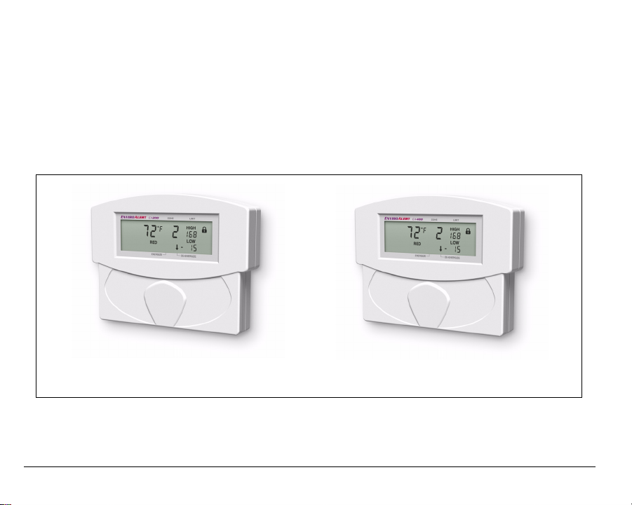
The EA200 / EA400 is easily mounted directly to a 2-gang electrical enclosure, or to
walls.
EA200 EA400
Figure 1. EnviroAlert EA200 and EA400
4 D-011-0093
Page 7

EnviroAlert EA200
Figure 2 shows a simplified functional diagram of the EA200 interfaces and functions.
The EA200 provides two Zones of monitoring as follows:
Zone 1 – Zone 1 is permanently programmed as a temperature monitor using a
temperature sensor built-in to the EA200.
Zone 2 – Zone 2 is equipped with a sensor input connector that can be connected to
any one of a variety of sensors. Using the appropriate sensor, Zone 2 can be used
to monitor temperature, humidity, or presence of water at remote locations.
Each Zone has its own Form C relay output that activates when a monitored
environmental condition exceeds the programmed range. An AUX (Auxiliary) Output
relay is activated whenever any Zone is in alarm. It can be used to provide a single
output to the alarm panel or to an optional audible alarm.
D-011-0093 5
Page 8

Figure 2. EA200 Functional Diagram
6 D-011-0093
Page 9

EnviroAlert EA400
Figure 3 shows a simplified functional diagram of the EA400 interfaces and functions.
The EA400 provides four Zones of monitoring as follows:
Zones 1 through 4 – Each Zone is equipped with a sensor input connector that can
be connected to any one of a variety of sensors (the EA400 is not equipped with a
built-in sensor). Using the appropriate external sensor, each Zone can be used to
monitor temperature, humidity, or presence of water. Programming and usage of
each Zone is fully independent of each other.
Each Zone has its own Form C relay output that activates when a monitored
environmental condition exceeds the programmed range. An AUX (Auxiliary) Output
relay is activated whenever any Zone is in alarm. It can be used to provide a single
output to the alarm panel or to an optional audible alarm.
D-011-0093 7
Page 10
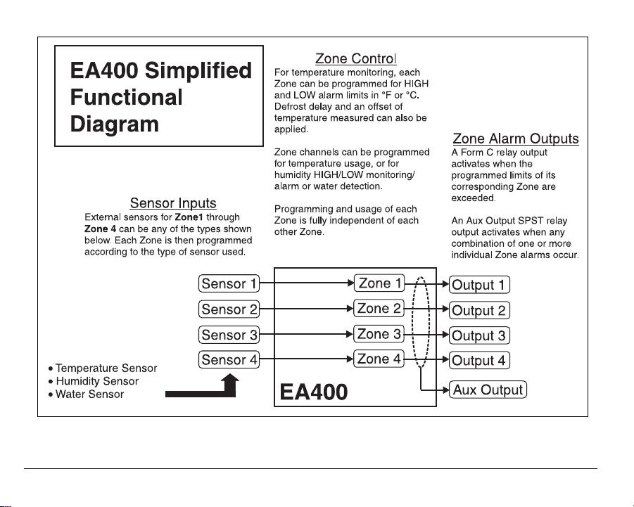
Figure 3. EA400 Functional Diagram
8 D-011-0093
Page 11
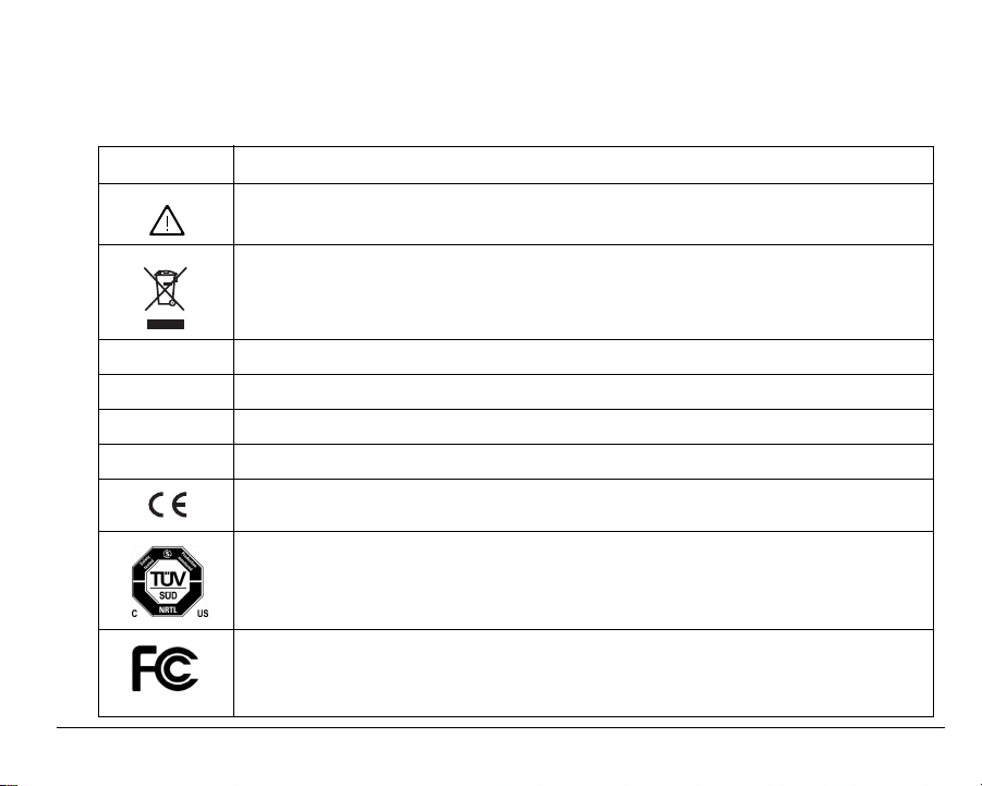
Symbols on the Product or Manual Labeling
Symbols on Product or Manual
Symbol Definition
Attention, consult accompanying documents or statements.
For product disposal, ensure the following:
• Do not dispose of this product as unsorted municipal waste.
• Collect this product separately.
• Use collection and return systems available to you.
NO / NC / C Normally Open, Normally Closed, and Common relay contact terminals
AUX Form C relay output that activates upon an alarm from any of the zones.
WEEE Waste Electrical and Electronic Equipment
RoHS Restriction of Hazardous Substances
Products intended for sale within the European Union are marked with the CE Mark,
which indicates compliance to applicable Directives and European Norms (EN).
The TUV certification combines electrical safety certification for Canada (SCC), United
States (NRTL), and Europe (EU Directives). These products were voluntarily tested
according to the relevant safety requirements and mentioned properties pertaining to this
certification mark.
This device complies with Part 15 of the FCC Rules. Operation is subject to the following
two conditions: (1) This device may not cause harmful interference, and (2) this device
must accept any interference received, including interference that may cause undesired
operation.
D-011-0093 9
Page 12
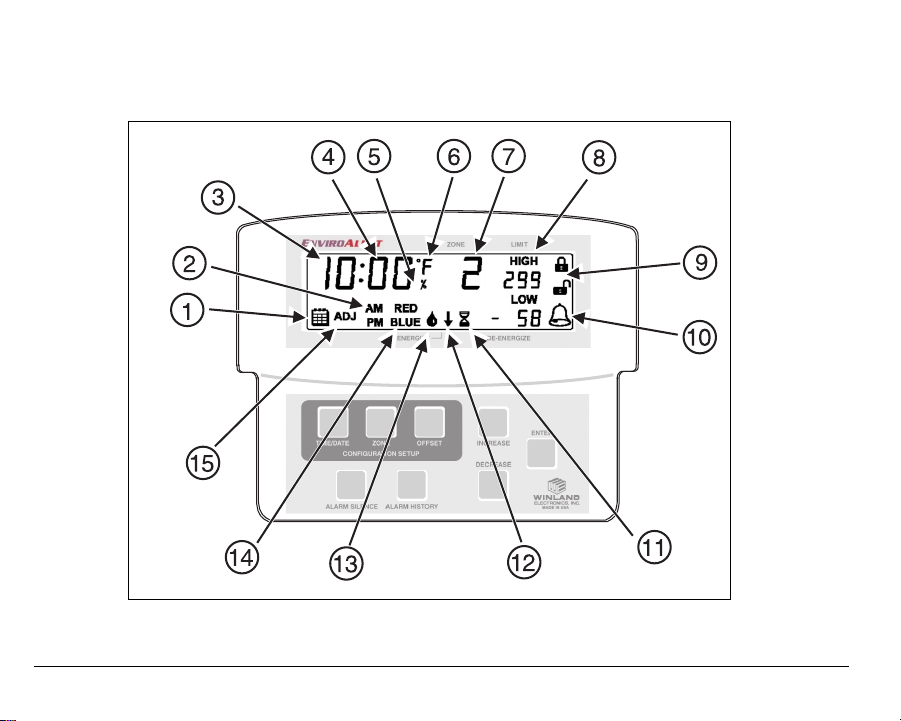
Display and Icons
Figure 4 shows and describes the display formats and icons.
Figure 4. EA200 / EA400 Display and Icons
10 D-011-0093
Page 13
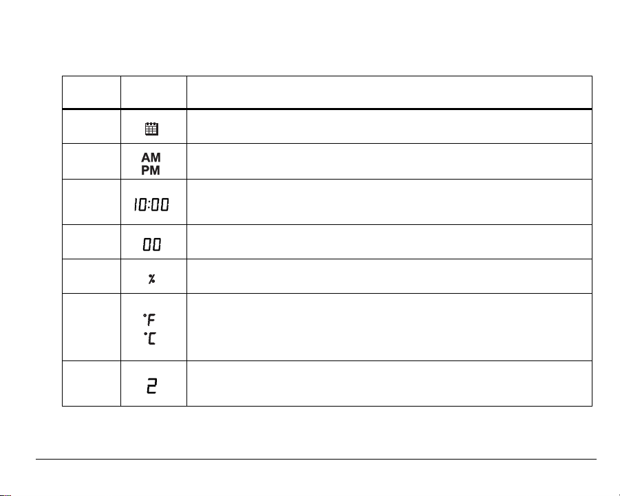
Display Icons
Index
No. Icon Function
1
2
3
4
5
6
7
Date icon.
Indicates EA200 / EA400 Date Set mode is accessed.
Time Set display.
Indicates Time Set mode is accessed.
Time/Date/Year display.
During setup, multiple function display for setting year (4-digit), date
(month.day), and time (hours:minutes).
Temperature/Humidity display.
Displays temperature and humidity values for designated Zone.
Humidity Mode icon.
Indicates Zone is programmed for monitoring humidity.
Temperature icon.
Indicates Zone is programmed for monitoring temperature. °F or °C indicates
measurement units selection.
Running display also shows monitored temperature for Zones programmed for
temperature monitoring.
Zone display.
During programming, indicates the Zone being programmed.
Display represents active data for Zone indicated.
D-011-0093 11
Page 14
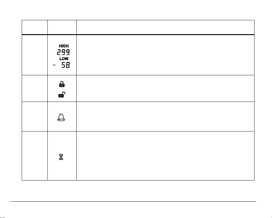
Display Icons — continued
Index
No. Icon Function
Limit display.
Shows the programmed HIGH limit and LOW limit points where measured con-
8
9
10
11
ditions exceeding limits will trigger an alarm for the related Zone.
• When programmed for temperature, the limit range allowed is between 299
degree units to –58 degree units.
• When programmed for humidity, the limit range allowed is between 100
RH% units to 0 RH% units.
Locked and Unlocked icons.
Indicates EA200 / EA400 lock status.
When EA200 / EA400 is in locked mode, programming cannot be changed; no
configuration modes are accessible.
Alarm icon.
When flashing, indicates that a Zone is in an alarm state. When steadily illumi-
nated, indicates that an alarm condition exists, but the programmed time delay
interval has not yet elapsed. When time delay period elapses, the icon will begin
flashing.
Delay Time Entry Mode icon.
During programming, indicates selection of delay time mode (up to 120 minutes
delay can be entered). When icon appears, a delay time (in minutes) can be
entered. With a delay programmed for the Zone, conditions exceeding the programmed limits (such as during a defrost cycle) are ignored for the duration of
the programmed delay.
This function is typically used to prevent false alarms for freezers and coolers
that have defrost cycles or doors that are opened frequently.
12 D-011-0093
Page 15
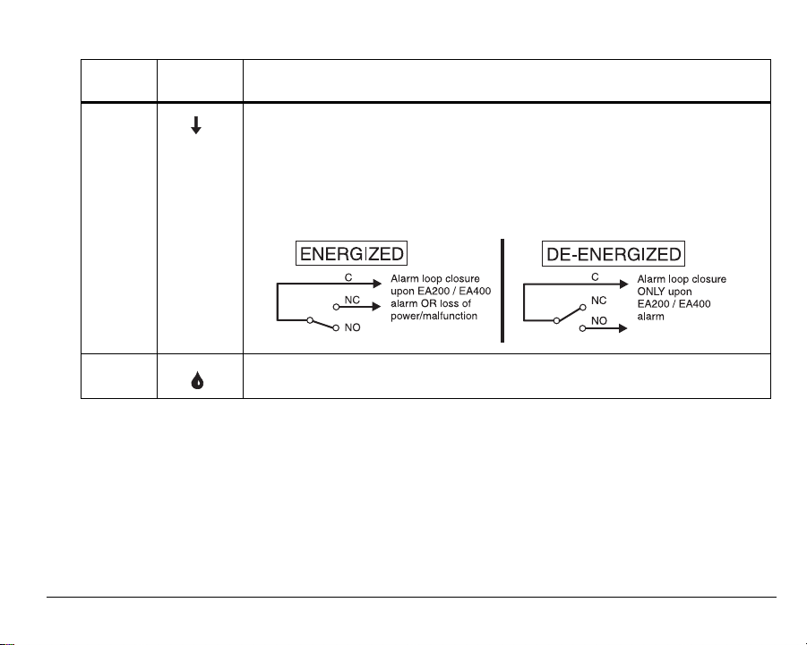
Display Icons — continued
Index
No. Icon Function
Alarm Output Relay Mode icon.
During programming, indicates selection of energized or de-energized alarm
output relay state for the Zone being programmed.
• Down arrow points to ENERGIZE when energized relay mode is selected
(relay is energized with no alarms; relay de-energizes upon alarm).
• Down arrow points to DE-ENERGIZE when de-energized relay mode is
12
selected (relay is de-energized with no alarms; relay energizes upon alarm).
13
D-011-0093 13
Water Presence Mode icon.
Indicates Zone is programmed for detecting presence of water.
Page 16
Display Icons — continued
Index
No. Icon Function
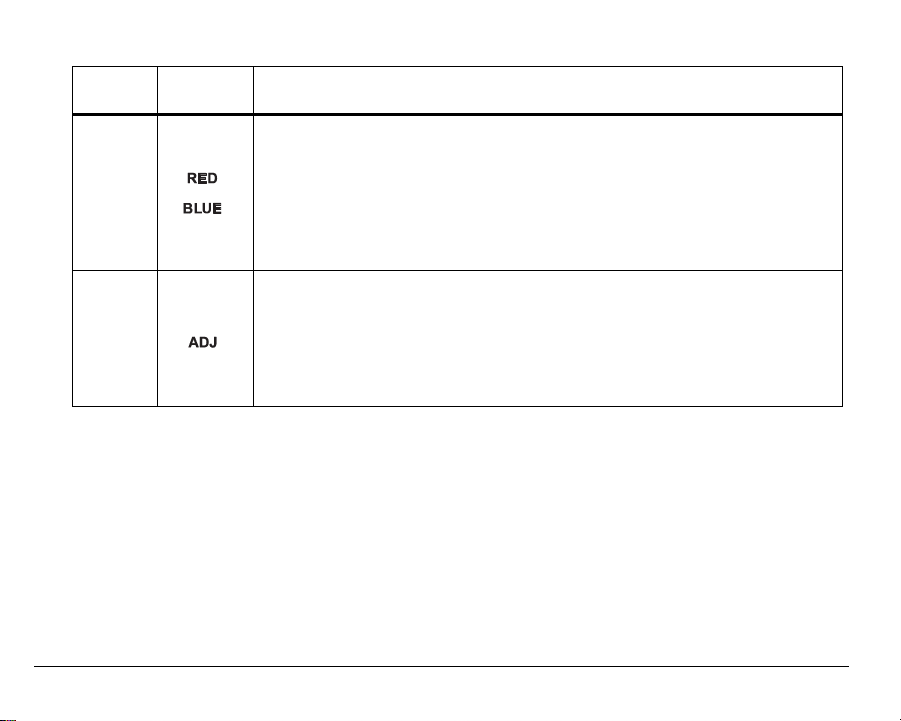
Temperature Sensor Type display.
During temperature monitoring programming, sensor type (based on conditions
expected for Zone) is entered.
14
15
• RED is selected when a “Red” (high-temperature range) sensor is to be used.
• BLUE is selected when a “Blue” (low-temperature range) sensor is to be
used.
Note: See “Accessories” on page 44 for more information regarding sensor
types and appropriate usage.
Offset Adjust icon.
Indicates that OFFSET (± 9 units) has been selected (this is selected by press-
ing the OFFSET key).
If desired, offset allows the temperature or humidity reading for the selected
Zone to be offset by a value that aligns the reading displayed on the EA200 /
EA400 with that of existing equipment, thereby correlating the EA200 / EA400
reading with that of existing equipment.
14 D-011-0093
Page 17

Keys
Figure 5 shows and describes the entry keys.
Figure 5. EA200 / EA400 Keys
D-011-0093 15
Page 18

Entry Keys
Index
No. Key Function
ALARM
16
17
18
19
16 D-011-0093
SILENCE key
TIME/DATE key When pressed in Unlocked mode, accesses Time/Date set mode.
ZONE key • When pressed in Unlocked mode during programming, allows
OFFSET key When pressed, allows offset entry for Zone displayed. (See Offset
Multi-function key:
• If alarm occurs, pressing key interrupts the auxiliary output relay for
10 minutes.
• Pressing key along with ENTER key toggles EA200 / EA400
between Locked and Unlocked modes.
When pressed again, exits mode.
access to Zone programming.
• When pressed during normal operation, allows selection of the
Zone to be displayed. When pressed again, exits mode.
Adjust icon (Index 13) in Display Icons table for more information.)
Page 19

Entry Keys — continued
Index
No. Key Function
INCREASE
DECREASE
keys
20
21
22
D-011-0093 17
ENTER key When pressed, saves a mode selection or numeric value entry. After
ALARM
HISTORY key
Select programming mode or value by pressing INCREASE or
DECREASE key to:
• Scroll through available selections pertaining to a mode.
• Increase or decrease numeric value pertaining to a mode (for
example, selection of temperature HIGH and LOW limits).
• Toggle between Zones in Programming mode. Zone selected using
these keys will display values for 10 seconds.
Note: Holding the INCREASE or DECREASE key automatically
scrolls through the full range of numeric values or mode choices.
pressing ENTER within a programming sequence, the EA200 /
EA400 proceeds to the next item requiring programming.
When pressed, the EA200 / EA400 displays history relating to
alarms. If multiple alarms exist, pressing the INCREASE or
DECREASE key steps through all stored alarms.
Press and hold ALARM HISTORY key for 5 seconds to clear alarm
history.
Page 20

Installation
Tools and Supplies Required
Below is a list of typically required tools and supplies:
#2 Flat-Blade Screwdriver
Sensors (not supplied; see “Accessories” on page 44)
Sensor Wiring (typically 18-22 AWG twisted-pair; not supplied)
Alarm Wiring (typically 18-22 AWG; see EA200 / EA400 Output (Alarm)
Connections)
Power Supply Requirements
Power source must furnish REGULATED 11 to 14VDC (EA200-12 and EA400-12) or 23
to 26VDC (EA200-24 and EA400-24). Power can be supplied using a REGULATED
AC/DC adapter (not supplied; see “Accessories” on page 44), or connect directly to a
REGULATED DC power supply from an alarm panel.
Note: Where required, this equipment is to be isolated from the mains supply by a
limited power source as specified in EN60950.
Note: All terminals must be connected to a Class 2 Power Limited Circuit complying
with the National Electric Code NFPA 70, Article 725.
Note: See “Specifications” on page 47 for power supply requirements.
18 D-011-0093
Page 21

Selecting Mounting Location for EA200 / EA400
Select a mounting location for the EA200 / EA400 considering the following:
Install the EA200 / EA400 where authorized personnel can readily access the
device. If required, consideration should be made regarding a location that
discourages unauthorized access.
Install the EA200 / EA400 such that the maximum cabling distance between the
sensor and the EA200 / EA400 does not exceed 304 m (1000 ft.).
Install the EA200 / EA400 in a location that meets the operating environmental
conditions (see “Specifications” on page 47). Additionally, if Zone 1 (built-in
temperature sensor) of an EA200 is being used, the EA200 must be installed in the
environment for which it is intended to monitor.
RF interference will have an adverse effect on the operation of the EnviroAlert. Do
NOT place the unit, wiring, or sensors near a potential source of interference.
CAUTION: Do not install the EA200 or EA400 in coolers or freezers.
Mounting the EA200 / EA400
The EA200 / EA400 uses a removable rear mounting plate which is attached to a
mounting surface (either a 2-gang electrical enclosure or surface mount).
1. Remove the rear mounting plate from the EA200 / EA400 main chassis as follows:
D-011-0093 19
Page 22

• At bottom of EA200 / EA400, pull the rear mounting plate down and away
from the EA200 / EA400 main chassis. The retainer tabs on the main chassis
will disengage from the holes in the rear mounting plate.
• Completely remove the mounting plate from the EA200 / EA400 main
chassis by disengaging the mounting plate upper hinges from the mating
tabs on the EA200 / EA400 main chassis.
2. Mount the mounting plate as follows:
• Mounting to 2-gang enclosure:
Use four (4) machine screws to secure the mounting plate to the mating
holes in the 2-gang enclosure.
• Mounting to drywall surface:
Place the mounting plate in mounting position. Mark the four mounting hole
locations. Install drywall anchors and secure the mounting plate to anchors.
Note: Where mounted to wall, a wiring access hole should be prepared at this time.
All wiring must pass through the opening in the center of mounting plate.
20 D-011-0093
Page 23

Connecting the EA200 / EA400
Note: Make certain all wiring to be connected is passing through the opening in cen-
ter of mounting plate.
Note: All terminals must be connected to a Class 2 Power Limited Circuit
complying with the National Electric Code NFPA 70, Article 725.
Note: Where required, this equipment is to be isolated from the mains supply by a
limited power source as specified in EN60950.
EA200 / EA400 Connectors
Figure 6 shows and describes the functions of the EA200 / EA400 connectors.
Note: All connections to the EA200 / EA400 circuit board header connectors are
made using Terminal Block Adapters (supplied with the EA200 / EA400 and
with sensors; and available as an accessory item). To ease connection of
stripped wire ends to the adapters, the adapters can be removed from the circuit board header connectors. Connect stripped wire ends to the adapters as
follows:
• Remove the adapter from the circuit board by pulling the adapter up and off
of the circuit board header connector.
• Insert stripped wire ends into side of adapter. Secure the connections using
the set screws on the adapter. Check the connection by lightly pulling on
each connection.
• After connecting the wire ends to the adapter, align the adapter to the
header pins where connection is desired, and press the adapter fully onto
the header connector pins.
D-011-0093 21
Page 24
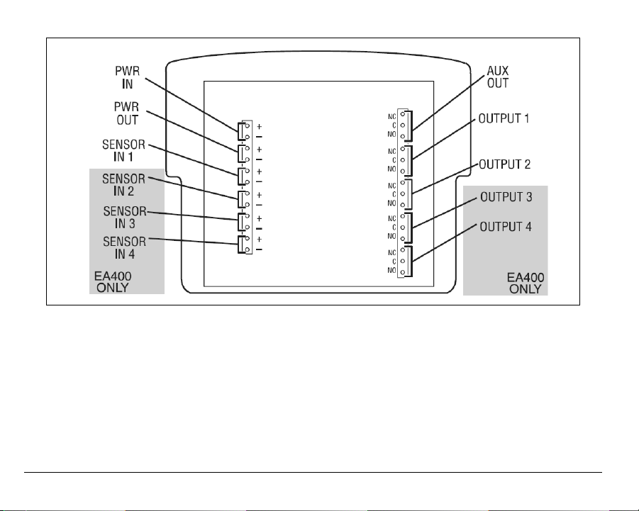
Figure 6. EA200 / EA400 Connectors
22 D-011-0093
Page 25
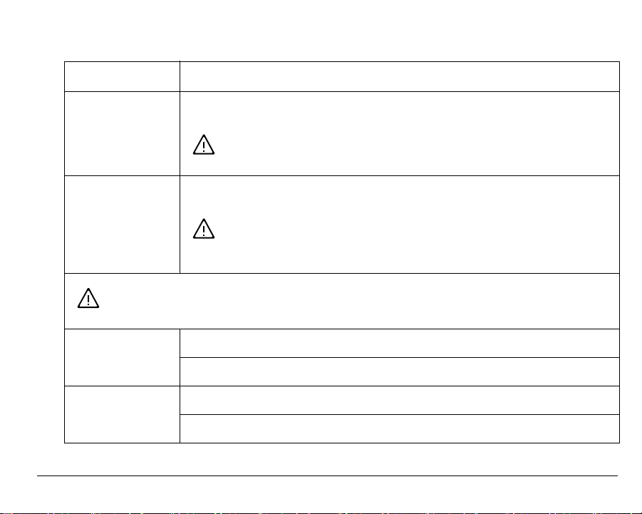
EA200 / EA400 Connectors
Connector Function
PWR IN Provides power connection for unit. Be sure to observe proper voltage requirements
for both 12V and 24V models.
CAUTION: Observe (+) and (-) polarity markings screened on
circuit board. EA200 / EA400 can be damaged if power polarity
is reversed.
PWR OUT Provides power to accessories used with the EA200 / EA400 (such as HA-III+ Humid
Alert).
CAUTION: Only connect accessories specified in this manual to
the PWR OUT connection. Connection of unsuitable loads to
this connection may damage the power supply and EA200 /
EA400, or result in improper or unreliable operation.
CAUTION: Only connect sensors specified in this manual to the SENSOR IN 1
through SENSOR IN 4 connections. Unverified sensors may damage EA200 /
EA400, or result in improper or unreliable operation.
SENSOR IN 1 EA200: Input for Zone 2 external temperature, water, or humidity sensor.
EA400: Input for Zone 1 external temperature, water, or humidity sensor.
SENSOR IN 2 EA200: Not available (blank position).
EA400: Input for Zone 2 external temperature, water, or humidity sensor.
D-011-0093 23
Page 26
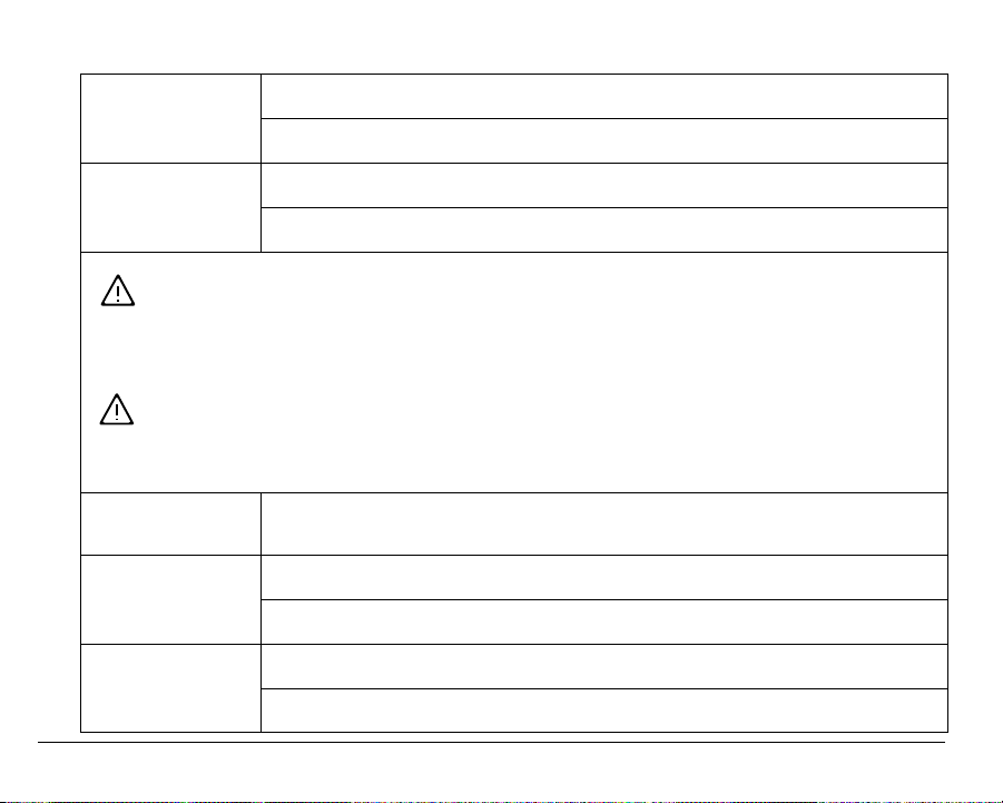
EA200 / EA400 Connectors — continued
SENSOR IN 3 EA200: Not available (blank position).
EA400: Input for Zone 3 external temperature, water, or humidity sensor.
SENSOR IN 4 EA200: Not available (blank position).
EA400: Input for Zone 4 external temperature, water, or humidity sensor.
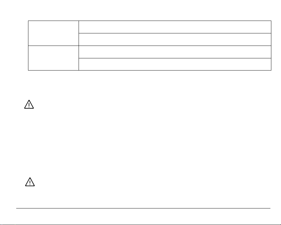
WARNING: EA200 / EA400 relay outputs are intended only for use as low-voltage,
low-current alarm connections, and not for direct switching or control of AC-mains
powered loads. Additionally, local codes may further dictate or limit the types of
loads and associated wiring to be used with the low-current Form C relay outputs
used with the EA200 / EA400. Connecting AC-mains type circuits to the EA200 /
EA400 may result in an electric shock and/or fire hazard.
CAUTION: Do not connect a load to the AUX OUT or OUTPUT 1 through OUTPUT 4
relay outputs that exceeds limitations stated in the Specifications section of this
manual. Loads exceeding the specified limitations may damage EA200 / EA400, or
result in improper or unreliable operation.
AUX OUT Form C relay output that activates upon any alarm. Allows for a single output to an
OUTPUT 1 EA200: Form C relay alarm output for built-in sensor (Zone 1).
OUTPUT 2 EA200: Form C relay alarm output for external sensor (Zone 2).
24 D-011-0093
alarm panel. This relay cannot be configured for energized or de-energized.
EA400: Form C relay alarm output for Zone 1.
EA400: Form C relay alarm output for Zone 2.
Page 27
EA200 / EA400 Connectors — continued
OUTPUT 3 EA200: Not available (blank position).
EA400: Form C relay alarm output for Zone 3.
OUTPUT 4 EA200: Not available (blank position).
EA400: Form C relay alarm output for Zone 4.
EA200 / EA400 Power Connections
CAUTION: Do not connect or disconnect power, sensor, or alarm wiring with power
applied. Connecting and disconnecting EA200 / EA400 with power connected may
damage EA200 / EA400, or result in improper or unreliable operation.
1. Using a Terminal Block Adapter, connect power supply + and – leads to PWR IN (+)
and (–) on EA200 / EA400 circuit board header connector. Observe proper polarity.
Make sure to use a REGULATED power supply.
2. If PWR OUT (supplied from EA200 / EA400 circuit board) is to be used, connect +
and – leads to PWR OUT (+) and (–) on EA200 / EA400 circuit board header
connector using a Terminal Block Adapter.
CAUTION: Only connect accessories specified in this manual to the PWR OUT connection. Connection of unsuitable loads to this connection may damage the power
supply and EA200 / EA400, or result in improper or unreliable operation.
D-011-0093 25
Page 28

EA200 / EA400 Sensor Connections
Note: Sensors required should be on-hand before attempting installation. Refer to
“Accessories” on page 44 for information regarding available sensors and their
recommended applications.
Note: The EA200 / EA400 can be used with earlier-version Winland temperature
sensors (
Model Numbers TA-S-D, TA-S-H, TA-S-L). However, for new
installations it is recommended that the current Winland temperature sensors
be used. See “Accessories” on page 44 for descriptions and part numbers of
current Winland sensors.
1. Install and wire all required external (remote location) sensors between the sensor
and the EA200 / EA400 mounting location. Use a wiring scheme that identifies
sensor wiring polarity. (The
TEMP-H-S, TEMP-L-S, TEMP-L-W, an
d TEMP-H-W
thermistor temperature sensors are not polarity-sensitive.)
2. Determine the sensor-to-Zone allotment to be used with the EA200 or EA400 being
installed. The table below shows the lists the Zones for the EA200 and EA400.
3. Using the Terminal Block Adapter included with the sensor, connect the sensor
wires to the appropriate SENSOR IN (+) and (–) connector on EA200 / EA400 circuit
board header connector as shown in Figure 7. Where applicable, observe proper
polarity.
4. Repeat the above step for each sensor.
26 D-011-0093
Page 29
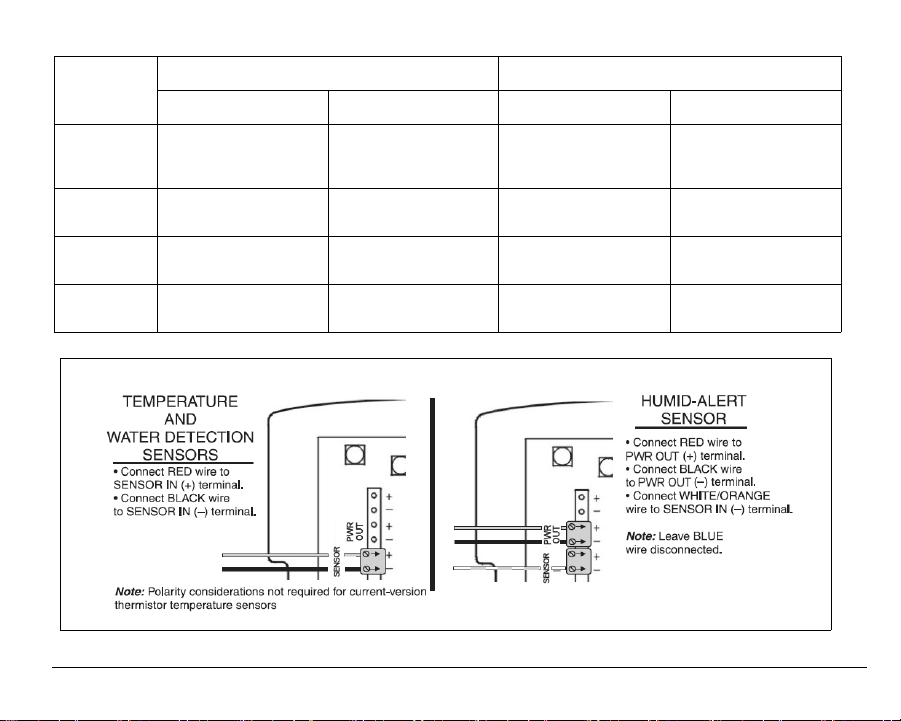
Sensor IN Corresponding Alarm Outputs
Zone
1 no external
2 SENSOR IN 1
3 not available SENSOR IN 3
4 not available SENSOR IN 4
EA200 EA400 EA200 EA400
connection
(built-in temp. Zone)
(+) (–)
SENSOR IN 1
(+) (–)
SENSOR IN 2
(+) (–)
(+) (–)
(+) (–)
OUTPUT 1
NC C NO
OUTPUT 2
NC C NO
not available OUTPUT 3
not available OUTPUT 4
OUTPUT 1
NC C NO
OUTPUT 2
NC C NO
NC C NO
NC C NO
Figure 7. EA200 / EA400 Sensor Connections
D-011-0093 27
Page 30

EA200 / EA400 Output (Alarm) Connections
1. For all alarm loops to be controlled by the EA200 / EA400, install all required wiring
from alarm loops to the EA200 / EA400 mounting location.
2. Determine the alarm-to-Zone allotment to be used with the EA200 or EA400 being
installed. See the table above in EA200 / EA400 Sensor Connections.
3. Connect the alarm loop leads to the Terminal Block Adapter. Attach the adapter to
terminals C and either NC or NO on the appropriate circuit board header connector.
See Figures 8 and 9.
Figures 8 and 9 show typical alarm loop wiring configurations. Figure 8 shows an
alarm loop where alarm power is derived from the alarm loop. Figure 9 shows an
alarm loop where alarm power is derived from the power supply feeding the EA200 /
EA400.
In both cases, the configuration shown uses the Alarm Output Relay mode set to
“DE-ENERGIZED” (alarm sent when relay energizes and closes).
To configure for ENERGIZED operation, the Zone should be programmed for
ENERGIZED, and the NC terminal of the output relay should be used instead of NO.
4. Repeat the above step for each alarm loop.
28 D-011-0093
Page 31
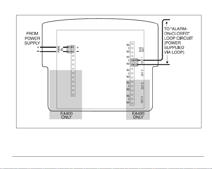
Figure 8. Typical Alarm Loop Wiring Configuration (External Power)
D-011-0093 29
Page 32
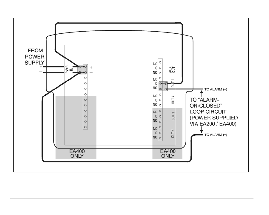
Figure 9. Typical Alarm Loop Wiring Configuration (Self-Powered)
30 D-011-0093
Page 33

5. Making certain wiring is not pinched or otherwise stressed, re-install the EA200 /
EA400 main chassis onto the mounting plate (installed in Mounting the EA200 /
EA400) as follows:
• Engage the mating tabs on the EA200 / EA400 main chassis into the
mounting plate upper hinges.
• Pivot the bottom of the EA200 / EA400 main chassis into closed position
while aligning the retainer tabs on the main chassis with the holes in the rear
mounting plate. Snap the main chassis closed onto the mounting plate.
When properly closed, the main chassis and mounting plate mating surfaces
will be flush. Make certain no wiring is protruding between mating surfaces.
6. The AUX output can be connected to either a local buzzer or strobe. It can also be
used as a single output to an alarm panel.
D-011-0093 31
Page 34

Setup
When powered-up, the EA200 / EA400 is ready to step through the stages where
programming settings are entered. As an overview, the EA200 / EA400 entry
progression is as follows:
Lock / Unlock
Date / Time Set
Program (set up) Zones
Note: Unless otherwise noted, all steps apply equally to EA200 or EA400.
Note: During Setup, a flashing display indicates the EA200 / EA400 is waiting for
data to be entered and saved.
Power-up and Unlocking for Programming
1. Apply power to the EA200 / EA400. All segments of the LCD display should
momentarily appear. The (Locked) icon appears.
2. Simultaneously press and release the ALARM SILENCE and ENTER keys. The
(Unlocked) icon appears.
32 D-011-0093
Page 35
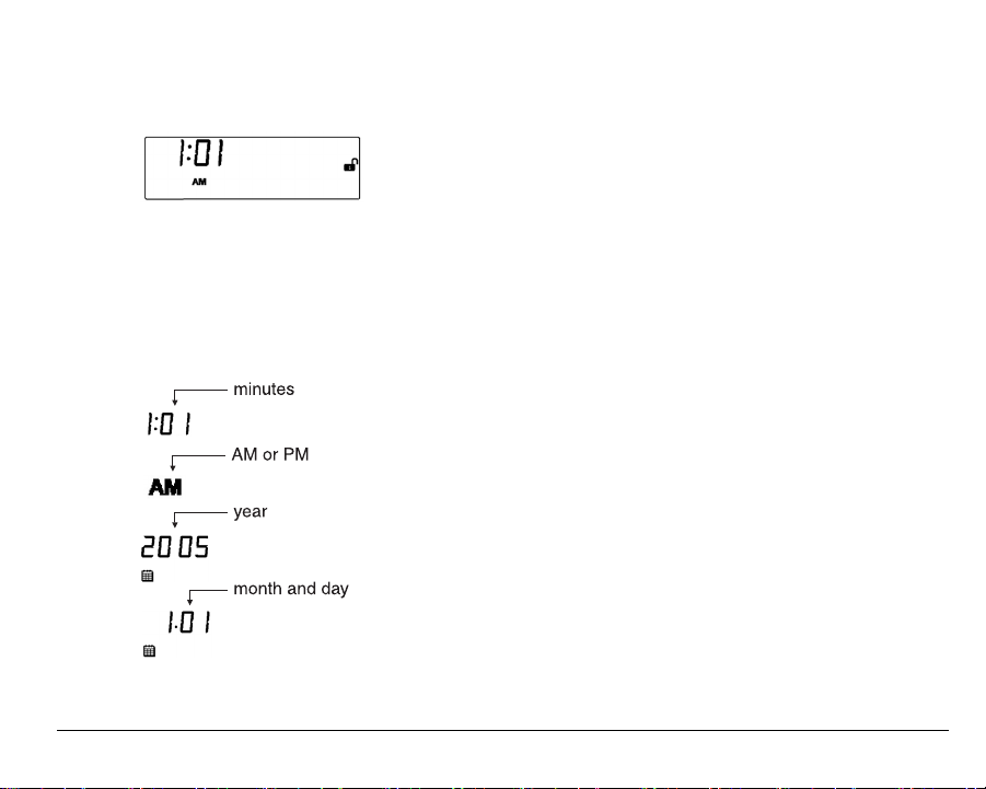
Setting Time and Date
1. Press the TIME/DATE key. The Hours display appears.
2. Enter current hour (flashing) by using the INCREASE or DECREASE keys to scroll
to the current hour, then press the ENTER key.
3. Enter the remaining data (in the sequence as shown below) for current date and
time by similarly using the INCREASE or DECREASE keys to scroll to the desired
setting, and then pressing the ENTER key.
D-011-0093 33
Page 36
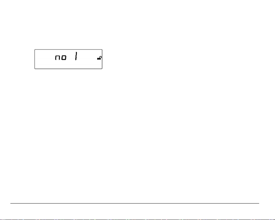
Programming the Zones
Program each Zone as follows:
1. Press the ZONE key. The Zone display appears.
2. Enter the Zone desired to be programmed (flashing) by using the INCREASE or
DECREASE keys to scroll to the desired Zone, and then press the ENTER key.
3. Enter the remaining data (from the choices in the sequence shown below) for the
Zone being programmed by similarly using the INCREASE or DECREASE keys to
scroll to the desired setting, and then pressing the ENTER key.
34 D-011-0093
Page 37
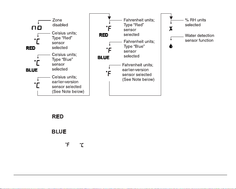
Note: Sensor types (“Red”, “Blue” or plain °F or °C) refer to the Zone programming
required for the type of sensor used:
• settings are used for current-version thermistor temperature sensors
TEMP-H-S and TEMP-H-W.
• settings are used
for current-version thermistor temperature sensors
TEMP-L-S and TEMP-L-W.
• Plain or settings are used for installations where earlier-version tem-
perature sensors (Model numbers TA-S-D, TA-S-H, TA-S-L) are
already in place. For new installations, it is recommended that the RED
and BLUE thermistor temperature sensors listed above be used.
Refer to “Accessories” on page 44 for detailed information, if required.
D-011-0093 35
Page 38

Note: If a Zone is not to be used, set the Zone to Disabled ( ). If an unconnected
Zone is not disabled, nuisance alarms may occur. Proceed to step 1 above to
program other Zones.
Note: All sensor selections (other than Disabled) require that the Zone be properly
connected to the sensor type entered during programming.
Note: The sequencing shown here assumes using the INCREASE KEY to scroll
through the choices. The opposite sequence occurs using the DECREASE
key.
4. Depending on the monitoring function selected above, proceed as follows:
• If Tempe rature function ( ) or Humidity function ( ) was selected, go to
step 5.
• If Water Detection function ( ) was selected, go to step 8.
5. When the display shown below appears, enter the High limit desired to be
programmed (flashing) by using the INCREASE or DECREASE keys to scroll to the
desired value, then press the ENTER key.
6. Enter the Low limit desired to be programmed (flashing) by using the INCREASE or
DECREASE keys to scroll to the desired value, and then press the ENTER key.
36 D-011-0093
Page 39

7. When the Delay Time ( ) icon appears, if desired enter a Delay Time (in minutes)
to be programmed (flashing) by using the INCREASE or DECREASE keys to scroll
to the desired value, and then press the ENTER key. (Refer to Delay Time Entry
Mode icon in Display and Icons for more information about delay function.)
If delay is not desired, set to “0”, press the ENTER key, and proceed.
8. When the icon appears, select ENERGIZE or DE-ENERGIZE by using the
INCREASE or DECREASE keys to toggle to the desired setting, then press the
ENTER key. (Refer to Alarm Output Relay Mode icon in Display and Icons for
more information about relay modes.)
9. At this point, programming for the Zone is complete. The display now shows the
entered limits (if applicable) and settings, along with the current monitored
parameter (if applicable).
10. Repeat steps 1 through 9 for other Zones.
D-011-0093 37
Page 40

Offset Adjustment
If desired, offset allows the temperature or humidity reading for the selected Zone to be
offset by a value that correlates the reading displayed on the EA200 / EA400 with that of
existing equipment.
Note: Allow a minimum of 15 minutes for temperature being monitored to
stabilize before making offset adjustments.
Enter an offset as follows:
1. Press the OFFSET key. The icon appears.
2. The flashing digit indicates the Zone at which the offset is to be applied. Use the
INCREASE or DECREASE keys to select the desired Zone, and then press the
ENTER key.
3. The flashing digit now indicates the offset value. Use the INCREASE or
DECREASE keys to select the desired offset value (±9 units range), and then press
the ENTER key.
The measured value added with the offset value is now displayed. (For example, if a
baseline measurement was 77 °F and an offset of –5° F was applied, the EA200 /
EA400 would now display 72 °F.)
38 D-011-0093
Page 41

Changing Programming for a Previously Programmed Zone
A Zone can be re-programmed as desired at any time. Press the ZONE key and perform
Zone programming as described in Programming the Zones.
Locking the Program Settings
The EA200 / EA400 can be locked after programming. Lock the EA200 / EA400 as
follows:
1. Simultaneously press and release the ALARM SILENCE and ENTER keys. The
(Locked) icon appears.
2. If desired, unlock by repeating the above step.
Using the EA200 / EA400 to Monitor Environmental
Conditions
When programmed and powered-up, the EA200 / EA400 provides a display of data
corresponding to all active Zones (running display). If more than one Zone is active, the
display cycles through and pauses on each Zone for approximately 5 seconds.
To immediately access a reading for a Zone, or to go back to a particular Zone, use the
INCREASE or DECREASE keys.
D-011-0093 39
Page 42
Normal (Non-Alarm) Mode Display
An example of a running display for a Zone programmed to monitor temperature is
shown below.
In general, normal non-alarm indication for any mode shows:
The measured data pertaining to the Zone.
No flashing data.
No (Alarm) icon.
Alarm Mode Displays
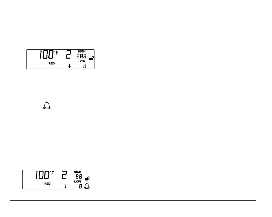
An example of a Alarm Display is shown below.
In the example shown below, the HIGH limit of 88° F has been exceeded by the
displayed 100° F ambient reading, thereby resulting in an alarm.
40 D-011-0093
Page 43

An alarm indication for any mode is shown by:
Flashing data corresponding to the Zone where the alarm is occurring.
An (Alarm) icon will flash during an alarm, and is solid if time delay is activated.
When time delay expires, icon will flash indicating an output relay has been
activated for the Zone in alarm.
To silence the auxiliary for 10 minutes, press the ALARM SILENCE key.
Note: Even if an alarm is silenced, the alarm display for the Zone is still displayed
until the alarm condition is corrected.
Note: If an alarm cannot be promptly corrected, and you wish to avoid repeated
alarms for the Zone, the Zone should be removed from service by setting the
Zone to Disabled ( ). Refer to Programming the Zones.
Viewing Alarm History
The Alarm History function stores up to 8 alarm events. View the alarm history as
follows:
1. Press the ALARM HISTORY key. The display shows the most recent stored alarm
alternately toggling between:
• Time of alarm occurrence, Zone number, and limit exceeded.
• Date of alarm occurrence, Zone number, and limit exceeded.
D-011-0093 41
Page 44
2. Press the DECREASE key to go to the next stored alarm. The next alarm is
displayed as described in step 1.
3. Press ALARM HISTORY to go back to the normal display.
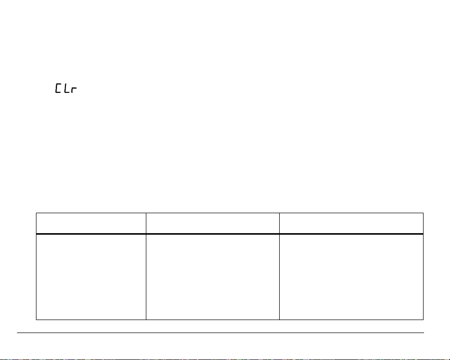
4. Clear the alarm history by pressing and holding the ALARM HISTORY key until
(Clear) is displayed, then release the key.
Troubleshooting
Operating or setup errors are displayed by flashing data on the display. Often, a
programming error will also result in an alarm for the mis-programmed Zone.
The table below shows and describes common error displays, along with corrective
action.
Troubleshooting
Error Display Cause Corrective Action
Flashing Zone digit and
flashing temperature reading of “–50° C” or “–58° F”.
42 D-011-0093
• Open connection between
sensor and EA200 / EA400
SENSOR IN connections.
• Bare wire end not properly
inserted into Terminal Block
Adapter.
• Defective sensor.
• Check connections. Make sure
any splices are OK. Make sure
Terminal Block Adapter is properly
connected to EA200 / EA400
header connector pins.
• Replace sensor as required.
Page 45

Troubleshooting — continued
Error Display Cause Corrective Action
Flashing Zone digit and
flashing temperature reading of “150° C” or “299° F”.
Excessive, obviously incorrect temperature reading
(for example, “32° F” displayed for nominal actual
temperature of 80° F).
ERR displayed EA200 / EA400 internal
D-011-0093 43
• Shorted connection between
sensor and EA200 / EA400
SENSOR IN connections.
• Defective sensor.
Wrong programming used for
sensor type used.
calibration error
• Check connections. Make sure
any splices are OK.
• Try Zone with another sensor.
Replace sensor as required.
Make certain programming matches
sensor type used. (For example, if
type “Red” sensor is used, make certain Zone is set for RED °F or RED
°C.)
Contact Winland Technical Service
at 1-800-635-4269.
Page 46
Accessories
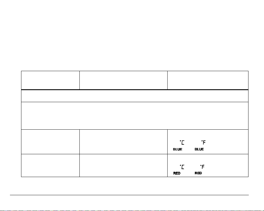
Note: In the table below, “Sensor Type Setting” specifies the appropriate sensor type
selection to be entered during Zone programming for the sensor type listed.
Where an accessory does not pertain to sensor type, this is denoted by “N/A”
(not applicable).
Accessories
Item
(Model Number) Description Sensor Type Setting
Temperature Sensors
Note: Although compatible with the EA200 / EA400, earlier-version temperature sensors (Model Numbers
TA-S-D, TA-S-H, TA-S-L) are not recommended for new installations.
Note: ° C or ° F measurement is a function of EA200 / EA400 programming. Temperature sensors can be
used equally for ° C or ° F measurement/monitoring.
Thermistor Low-Temp
(“Blue”) Sensor
(TEMP-L-S)
Thermistor High-Temp
(“Red”) Sensor
(TEMP-H-S)
44 D-011-0093
–50° C to 70° C (–58° F to 158° F)
For use in coolers and freezers.
Accuracy: +/-2°F
0° C to 150° C (32° F to 299° F)
Accuracy: +/-2°F
or setting
or setting
Page 47
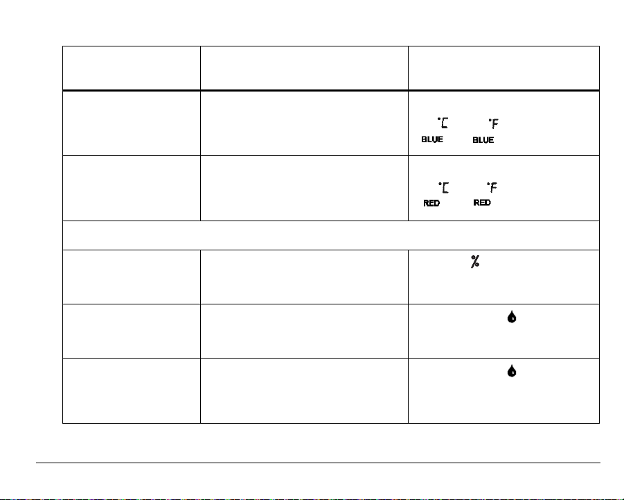
Accessories — continued
Item
(Model Number) Description Sensor Type Setting
Waterproof Thermistor
Low-Temp (“Blue”)
Sensor
TEMP-L-W)
(
Waterproof Thermistor
High-Temp (“Red”)
Sensor
(TEMP-H-W)
–50° C to 70° C (–58° F to 158° F)
Accuracy: +/-2°F
0° C to 105° C (32° F to 221° F)
Accuracy: +/-2°F
or setting
or setting
Other Sensors
Humidity Sensor
“Humid-Alert”
(
HA-III+)
Supervised Water
Sensor
(
W-S-S)
Supervised
Under-Carpet
Water Sensor
(W-UC-S)
D-011-0093 45
5% to 95% RH humidity monitoring
module.
Monitoring for presence of water. Water Detection
Monitoring for presence of water. Water Detection
Humidity setting
setting
setting
Page 48
Accessories — continued
Item
(Model Number) Description Sensor Type Setting
Other Accessories
Audible Alarm
Module
(BZ-1)
3-piece Terminal Block
Adapter Kit
(EA-TBK)
12VDC Power Supply
(United States)
(12VDCT)
12VDC Power Supply
(Europe)
(PN L-020-0085)
24VDC Power Supply
(Europe)
(PN L-020-0087)
46 D-011-0093
Buzzer that can be connected to
auxiliary rela
ble alert of alarm (1.5 to 24VDC).
Adapts
header connector pins on EA200 /
EA400 printed circuit board.
Regulated 110 VAC to 12 VDC @
300
able for use with EA200-12 /
EA400-12 (for North America only).
Regulated, Universal Input (90 to
264VAC) to 12VDC suitable for use
with EA200-12 / EA400-12 (for Europe
only).
Regulated, Universal Input (90 to
264VAC) to 24VDC suitable for use
with EA200-24 / EA400-24 (for Europe
only).
y output to provide audi-
stripped wire ends to the
mA (minimum) transformer suit-
N/A
N/A
N/A
N/A
N/A
Page 49
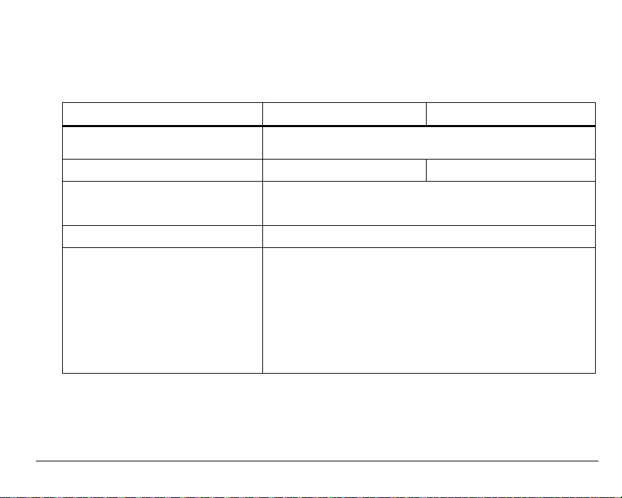
Specifications
Specifications
Item EA200 EA400
Dimensions Approximately 122 mm x 152 mm x 30.5 mm
Weight 0.25 kg (0.55 lb.) 0.27 kg (0.6 lb.)
Mounting Mountable directly to 2-gang standard electrical enclosure using
Case Material ABS, UL94V-0 rated
Input (Operating) Voltage Power source must furnish REGULATED 11 to 14VDC
(4.8” H x 6.0” W x 1.2” D)
pre-drilled holes on EA200 / EA400 rear case. Can be mounted
to drywall or similar surfaces using anchor screws (not included).
(EA200-12 and EA400-12) or 23 to 26VDC (EA200-24 and
EA400-24). Power can be supplied using a REGULATED
AC/DC adapter (not supplied; see “Accessories” on page 44), or
connect directly to a REGULATED DC power supply from an
alarm panel.
Note: Power supply requirement does not include additional
requirements for loads switched through alarm output relays
where power is derived from EA200 or EA400 terminal strip connections.
D-011-0093 47
Page 50

Specifications — continued
Item EA200 EA400
Low and High Adjust Range:
• Temperature:
–50°C to 150 °C
–58° F to 299° F
• Humidity:
• Water Presence:
Zones • (1) Temperature Zone
Sensors • (1) Built-in temperature
48 D-011-0093
5 to 95% RH
No Alarm / Alarm
Note: Usable range is also determined and may be limited by
the sensor used. See “Accessories” on page 44.
(using built-in temperature
sensor)
• (1) Connector for external
(wired) sensor
corresponding to Zone 2.
• Usable with Winland
temperature, humidity, or
water presence sensors
(see “Accessories” on page
44).
sensor; Range: 0°C to
50 °C (32° F to 122° F)
• Provision for (1) external
sensor (not supplied, see
“Accessories” on page 44).
(4) Connectors for external
(wired) sensors corresponding to Zones 1 through 4.
Usable with Winland temperature, humidity, or water presence sensors (see
“Accessories” on page 44).
• None included. See
“Accessories” on page 44.
Page 51
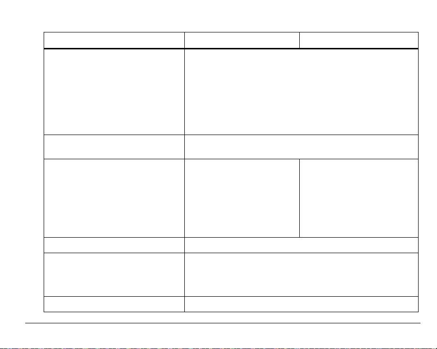
Specifications — continued
Item EA200 EA400
Sensor Type/Connection:
• Temperature:
2-wire, 18-22AWG; maximum 304 m (1000 ft.) cabling length
• Humidity:
• Water Presence:
Minimum Span Between High and
Low Limits
Relay Outputs • (2) Form C with 3-terminal
Relay Contact Ratings 1 A at 30 VDC
Relay Logic User configurable for:
Display Multiple icon Liquid Crystal Display (LCD)
D-011-0093 49
3-wire, 18-22AWG; maximum 304 m (1000 ft.) cabling length
2-wire, 18-22AWG; maximum 304 m (1000 ft.) cabling length
•4° C (° F)
•4% RH
NC/COM/NO connections
corresponding to Zones 1
and 2.
• (1) Form C with 3-terminal
NC/COM/NO used for Aux
Output alarm (combined
OR function of Zones 1 and
2).
• Alarm= energized coil, or
• Alarm= de-energized coil
Each zone individually configurable.
• (4) Form C with 3-terminal
NC/COM/NO connections
corresponding to Zones 1
through 4.
• (1) Form C with 3-terminal
NC/COM/NO used for Aux
Output alarm (combined OR
function of Zones 1 through
4).
Page 52
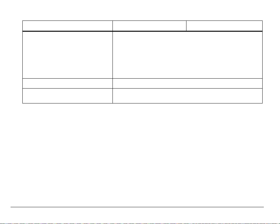
Specifications — continued
Item EA200 EA400
Device Environmental Operating
Range:
• Humidity:
• Temperature, Operating:
• Ambient Environmental Quality:
Conformity Certifications See page 52
Warranty One (1) Year Limited Warranty. See Warranty and Service Infor-
5 to 95% RH, non-condensing
0°C to 50°C (32° F to 122° F). Not for installation inside of
coolers or freezers.
Indoor use intended, non-corrosive environment
mation.
50 D-011-0093
Page 53

Warranty and Service Information
Winland Electronics, Inc. (“Winland”) warrants to the end user/purchaser that each product of its
manufacture shall be free from defects in material and factory workmanship for a period of one
year from the date of purchase, when properly installed and operated under normal conditions
according to Winland’s instruction.
Winland’s obligation under this warranty is limited to correcting, without charge, at its factory any
part or parts thereof which shall be returned to the factory, by the original purchaser, transportation
charges prepaid, within one year of the date of purchase and which upon examination, shall
disclose to Winland’s satisfaction to have been originally defective. Correction of such defects by
repair to, or supplying replacements for, defective parts shall constitute fulfillment of all Winland’s
obligations to purchaser under this limited warranty. Repair service performed by Winland after
one year from date of purchase will be for a reasonable service charge.
This limited warranty shall not apply to any of Winland’s products which have been subject to
misuse, negligence or accident or which have been repaired or altered outside of Winland’s
factory. The warranty is void if the Product’s housing or cover is removed.
Winland shall not be liable for loss, damage or expense resulting, directly or indirectly, from the
use of its products or any other cause.
THIS WARRANTY IS IN LIEU OF ALL OTHER WARRANTIES, EXPRESS OR IMPLIED,
INCLUDING, WITHOUT LIMITATION, ANY WARRANTIES OF MERCHANTABILITY, FITNESS
FOR PARTICULAR PURPOSES, NON-INFRINGEMENT AND TITLE, AND ANY WARRANTIES
ARISING FROM COURSE OF DEALING, USAGE OF TRADE OR OTHERWISE. ALL OTHER
REPRESENTATIONS MADE TO THE END USER/PURCHASER BY ANY OTHER PARTY ARE
ALSO EXCLUDED.
WINLAND SHALL NOT BE LIABLE TO ANY PERSON FOR INDIRECT, SPECIAL, INCIDENTAL
OR CONSEQUENTIAL DAMAGES OF ANY DESCRIPTION, WHETHER ARISING OUT OF
WARRANTY OR OTHER CONTRACT, NEGLIGENCE OR OTHER TORT, OR OTHERWISE.
Under no circumstances shall Winland’s liability under this limited warranty exceed the purchase
price paid by the end user/purchaser for the product.
No person, agent or dealer is authorized to give warranties on behalf of Winland nor to assume for
Winland any other liability in connection with any of its products.
D-011-0093 51
Page 54

WEEE Product Recovery/Recycling for EU Customers
In an effort to improve waste management in the European Union, the European Union has enacted directive
2002/96/EC on Waste Electrical and Electronic Equipment (WEEE Directive). According to the WEEE
Directive, Winland Electronics must take back waste electrical or electronic equipment covered under the
WEEE Directive, at its cost, for all product it puts on the market after July 1, 2006.
The Return Process: Contact Winland via our website at www.winland.com and go to the WEEE link on the
home page.
To request additional information regarding Winland’s RoHS and WEEE compliance initiative and how it might
impact your business, email [email protected].
EnviroAlert Certification Info
Radio Frequency Interference Requirements: This device complies with Part 15 of the FCC
Rules. Operation is subject to the following two conditions: (1) This device may not cause harmful
interference, and (2) this device must accept any interference received, including interference that
may cause undesired operation.
Safety Certification: The TUV certification combines electrical safety certification for Canada
(SCC), United States (NRTL), and Europe (EU Directives). These products were voluntarily tested
according to the relevant safety requirements and mentioned properties pertaining to this
certification mark. Tested according to: CAN/CSA C22.2 No. 61010-1:2004; UL 61010-1:2004; EN
61010-1:2001.
CE Marking and European Union Compliance: Products intended for sale within the European
Union are marked with the CE Mark, which indicates compliance to applicable Directives and
European Norms (EN). Amendments to these Directives or ENs are included:
Applicable Directives
Electromagnetic Compatibility Directive 89/336/EEC; Low Voltage Directive 73/23/EEC; RoHS Directive
2002/95/EC; WEEE Directive 2002/96/EC
Applicable Standards
Safety: CAN/CSA C22.2 No. 61010-1:2004; UL 61010-1:2004; EN 61010-1:2001
Statement of Compliance
Winland Electronics, Inc. hereby declares that this device is in compliance with all the applicable Directives,
89/336/EEC, 73/23/EEC. A Declaration of Conformity may be obtained from http://www.winland.com/doc/
52 D-011-0093
Page 55

WEEE Product Recovery/Recycling for EU Customers
In an effort to improve waste management in the European Union, the European Union has enacted directive
2002/96/EC on Waste Electrical and Electronic Equipment (WEEE Directive). According to the WEEE
Directive, Winland Electronics must take back waste electrical or electronic equipment covered under the
WEEE Directive, at its cost, for all product it puts on the market after July 1, 2006.
The Return Process: Contact Winland via our website at www.winland.com and go to the WEEE link on the
home page.
To request additional information regarding Winland’s RoHS and WEEE compliance initiative and how it might
impact your business, email [email protected].
EnviroAlert Certification Info
Radio Frequency Interference Requirements: This device complies with Part 15 of the FCC
Rules. Operation is subject to the following two conditions: (1) This device may not cause harmful
interference, and (2) this device must accept any interference received, including interference that
may cause undesired operation.
Safety Certification: The TUV certification combines electrical safety certification for Canada
(SCC), United States (NRTL), and Europe (EU Directives). These products were voluntarily tested
according to the relevant safety requirements and mentioned properties pertaining to this
certification mark. Tested according to: CAN/CSA C22.2 No. 61010-1:2004; UL 61010-1:2004; EN
61010-1:2001.
CE Marking and European Union Compliance: Products intended for sale within the European
Union are marked with the CE Mark, which indicates compliance to applicable Directives and
European Norms (EN). Amendments to these Directives or ENs are included:
Applicable Directives
Electromagnetic Compatibility Directive 89/336/EEC; Low Voltage Directive 73/23/EEC; RoHS Directive
2002/95/EC; WEEE Directive 2002/96/EC
Applicable Standards
Safety: CAN/CSA C22.2 No. 61010-1:2004; UL 61010-1:2004; EN 61010-1:2001
Statement of Compliance
Winland Electronics, Inc. hereby declares that this device is in compliance with all the applicable Directives,
89/336/EEC, 73/23/EEC. A Declaration of Conformity may be obtained from http://www.winland.com/doc/
52 D-011-0093
Page 56

D-011-0093 Rev. C
Manufactured in the U.S.A by
Winland Electronics
1950 Excel Drive, Mankato, MN, 56001
Outside MN Phone: 1-800-635-4269
Phone: 507-625-7231
Fax: 507-387-2488
©Winland Electronics, Inc. 2005
www.winland
security.com
 Loading...