


Limitations of the Alarm System or Device
While your alarm system or device is reliable and sophisticated, it does not offer guaranteed protection against
burglary, fire, or other emergency. Any security product, whether commercial or residential, is subject to
compromise or failure-to-warn for a variety of reasons. These include:
• Individuals may gain access through unprotected openings or have the technical sophistication to bypass
an alarm sensor or disconnect an alarm warning device.
• Monitoring devices will not operate without power. Devices powered by AC will not work if their AC power
supply is off for any reason. If the system has battery back-up, batteries that are not maintained can fail to
provide the necessary power for devices to function properly.
• Alarm warning devices such as sirens, bells, and horns may not alert people or wake up sleepers if they are
located on the other side of closed or partly closed doors. If warning devices are on a different level of the
residence from the bedrooms, they are less likely to waken or alert people inside the bedrooms.
• Telephone lines needed to transmit alarm signals from the premises to a central monitoring station may be
out of service and are subject to compromise by sophisticated means of attack.
• Signals sent by wireless transmitters may be blocked or reflected by metal before they reach the alarm
receiver. Even if the signal path has been recently checked during a weekly test, blockage can occur if a
metal object if moved into the path.
• Even if the system responds to the emergency as intended and is a monitored alarm system, the
authorities may not respond appropriately.
• This equipment, like other electrical devices, is subject to component failure. Even though this equipment is
designed to last as long as 20 years, the electronic components could fail at any time.
• The most common cause of an alarm system not functioning properly is due to inadequate maintenance.
Your alarm system should be tested weekly to make sure all detection devices are operating properly. Your
control panel and keypads should be tested, as well.
Installing an alarm system may make you eligible for lower insurance rates, but an alarm system is not a
substitute for insurance. Homeowners, property owners, and renters should continue to insure their lives and
property.

Table of Contents
General Information. . . . . . . . . . . . . . . . . . . . . . . . . . . . . . . . . . . . . . . . . . . . . . . . . . . . . . . . . . .3
EnviroAlert EA200. . . . . . . . . . . . . . . . . . . . . . . . . . . . . . . . . . . . . . . . . . . . . . . . . . . . . . . . . .5
EnviroAlert EA400. . . . . . . . . . . . . . . . . . . . . . . . . . . . . . . . . . . . . . . . . . . . . . . . . . . . . . . . . .7
Symbols on the Product or Manual Labeling . . . . . . . . . . . . . . . . . . . . . . . . . . . . . . . . . . . . .9
Display and Icons . . . . . . . . . . . . . . . . . . . . . . . . . . . . . . . . . . . . . . . . . . . . . . . . . . . . . . . . .10
Keys . . . . . . . . . . . . . . . . . . . . . . . . . . . . . . . . . . . . . . . . . . . . . . . . . . . . . . . . . . . . . . . . . . .15
Installation . . . . . . . . . . . . . . . . . . . . . . . . . . . . . . . . . . . . . . . . . . . . . . . . . . . . . . . . . . . . . . . . .18
Tools and Supplies Required . . . . . . . . . . . . . . . . . . . . . . . . . . . . . . . . . . . . . . . . . . . . . . . .18
Power Supply Requirements. . . . . . . . . . . . . . . . . . . . . . . . . . . . . . . . . . . . . . . . . . . . . . . . .18
Selecting Mounting Location for EA200 / EA400 . . . . . . . . . . . . . . . . . . . . . . . . . . . . . . . . .19
Mounting the EA200 / EA400 . . . . . . . . . . . . . . . . . . . . . . . . . . . . . . . . . . . . . . . . . . . . . . . .19
Connecting the EA200 / EA400 . . . . . . . . . . . . . . . . . . . . . . . . . . . . . . . . . . . . . . . . . . . . . .21
Setup . . . . . . . . . . . . . . . . . . . . . . . . . . . . . . . . . . . . . . . . . . . . . . . . . . . . . . . . . . . . . . . . . . . . .32
Power-up and Unlocking for Programming . . . . . . . . . . . . . . . . . . . . . . . . . . . . . . . . . . . . . .32
Setting Time and Date. . . . . . . . . . . . . . . . . . . . . . . . . . . . . . . . . . . . . . . . . . . . . . . . . . . . . .33
Programming the Zones . . . . . . . . . . . . . . . . . . . . . . . . . . . . . . . . . . . . . . . . . . . . . . . . . . . .34
Offset Adjustment . . . . . . . . . . . . . . . . . . . . . . . . . . . . . . . . . . . . . . . . . . . . . . . . . . . . . . . . .38
Changing Programming for a Previously Programmed Zone . . . . . . . . . . . . . . . . . . . . . . . .39
Locking the Program Settings . . . . . . . . . . . . . . . . . . . . . . . . . . . . . . . . . . . . . . . . . . . . . . . .39
D-011-0093 1

Using the EA200 / EA400 to Monitor Environmental Conditions . . . . . . . . . . . . . . . . . . . . . . . 39
Normal (Non-Alarm) Mode Display. . . . . . . . . . . . . . . . . . . . . . . . . . . . . . . . . . . . . . . . . . . . 40
Alarm Mode Displays . . . . . . . . . . . . . . . . . . . . . . . . . . . . . . . . . . . . . . . . . . . . . . . . . . . . . .40
Viewing Alarm History. . . . . . . . . . . . . . . . . . . . . . . . . . . . . . . . . . . . . . . . . . . . . . . . . . . . . .41
Troubleshooting . . . . . . . . . . . . . . . . . . . . . . . . . . . . . . . . . . . . . . . . . . . . . . . . . . . . . . . . . . . . 42
Accessories. . . . . . . . . . . . . . . . . . . . . . . . . . . . . . . . . . . . . . . . . . . . . . . . . . . . . . . . . . . . . . . . 44
Specifications . . . . . . . . . . . . . . . . . . . . . . . . . . . . . . . . . . . . . . . . . . . . . . . . . . . . . . . . . . . . . . 47
Warranty and Service Information. . . . . . . . . . . . . . . . . . . . . . . . . . . . . . . . . . . . . . . . . . . . . . . 51
WEEE Product Recovery/Recycling for EU Customers . . . . . . . . . . . . . . . . . . . . . . . . . . . . . . 52
EnviroAlert Certification Info . . . . . . . . . . . . . . . . . . . . . . . . . . . . . . . . . . . . . . . . . . . . . . . . . . . 52
2 D-011-0093

General Information
EA200
The EnviroAlert
ex
ceed the user-programmable HIGH LIMIT or LOW LIMIT set points. The alarm
ls a
signa
o
t
r
con
All setup is
cate the setup and parameter being configured. The LCD display assists the user
indi
during setup, and shows measured conditions for the monitored critical environment.
EA2
e
Th
s,
put
in
0
EA40
®
re pr
ovid
ls, security
one
using
d
and
0
0
with ea
er
p
f
dif
and EA400
ed via relay output
systems, or other
ont p
the fr
EA400
ch sensor
r
ima
can
r
ily in th
in
pr
a
nel
nitor
mo
put/ala
e numbe
rm channe
ovide alarm
s
t
can o
tha
ilar au
sim
th
nd
keys
a
multiple
l
r
of Zon
e
sig
nals
ate with
per
tom
ated equipment.
d
ical e
sign
at
can
spla
i
n
viro
ated a
e LCD
crit
e
d
s
th
when
monitored conditions
ar
n
Z
m p
ich us
usi
s
t
e”. The
on
red
a
nels, pr
es
ng
.
be
al
, wh
y
nme
s
a “
onito
m
ico
multipl
EA2
ocess
th
s
n
e
sen
00 and
at
or
s
D-011-0093 3
Using the appropriate accessory sensors (not supplied), the EA200 / EA400 monitors
and provides alarms for the following environmental conditions:
Temperature: from –50° C to 150° C (–58° F to 299° F)
Humidity: from 5% to 95% RH
Presence of water
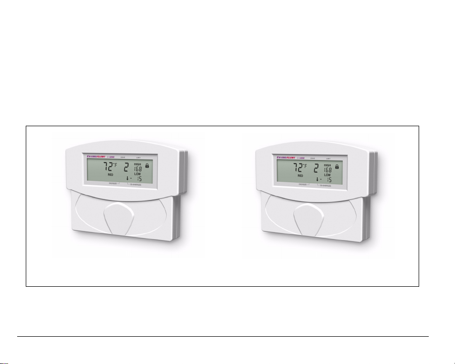
The EA200 / EA400 is easily mounted directly to a 2-gang electrical enclosure, or to
walls.
EA200 EA400
Figure 1. EnviroAlert EA200 and EA400
4 D-011-0093

EnviroAlert EA200
Figure 2 shows a simplified functional diagram of the EA200 interfaces and functions.
The EA200 provides two Zones of monitoring as follows:
Zone 1 – Zone 1 is permanently programmed as a temperature monitor using a
temperature sensor built-in to the EA200.
Zone 2 – Zone 2 is equipped with a sensor input connector that can be connected to
any one of a variety of sensors. Using the appropriate sensor, Zone 2 can be used
to monitor temperature, humidity, or presence of water at remote locations.
Each Zone has its own Form C relay output that activates when a monitored
environmental condition exceeds the programmed range. An AUX (Auxiliary) Output
relay is activated whenever any Zone is in alarm. It can be used to provide a single
output to the alarm panel or to an optional audible alarm.
D-011-0093 5

Figure 2. EA200 Functional Diagram
6 D-011-0093

EnviroAlert EA400
Figure 3 shows a simplified functional diagram of the EA400 interfaces and functions.
The EA400 provides four Zones of monitoring as follows:
Zones 1 through 4 – Each Zone is equipped with a sensor input connector that can
be connected to any one of a variety of sensors (the EA400 is not equipped with a
built-in sensor). Using the appropriate external sensor, each Zone can be used to
monitor temperature, humidity, or presence of water. Programming and usage of
each Zone is fully independent of each other.
Each Zone has its own Form C relay output that activates when a monitored
environmental condition exceeds the programmed range. An AUX (Auxiliary) Output
relay is activated whenever any Zone is in alarm. It can be used to provide a single
output to the alarm panel or to an optional audible alarm.
D-011-0093 7
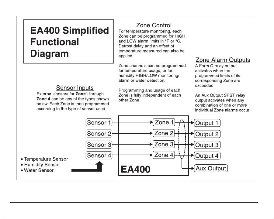
Figure 3. EA400 Functional Diagram
8 D-011-0093
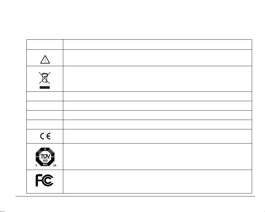
Symbols on the Product or Manual Labeling
Symbols on Product or Manual
Symbol Definition
Attention, consult accompanying documents or statements.
For product disposal, ensure the following:
• Do not dispose of this product as unsorted municipal waste.
• Collect this product separately.
• Use collection and return systems available to you.
NO / NC / C Normally Open, Normally Closed, and Common relay contact terminals
AUX Form C relay output that activates upon an alarm from any of the zones.
WEEE Waste Electrical and Electronic Equipment
RoHS Restriction of Hazardous Substances
Products intended for sale within the European Union are marked with the CE Mark,
which indicates compliance to applicable Directives and European Norms (EN).
The TUV certification combines electrical safety certification for Canada (SCC), United
States (NRTL), and Europe (EU Directives). These products were voluntarily tested
according to the relevant safety requirements and mentioned properties pertaining to this
certification mark.
This device complies with Part 15 of the FCC Rules. Operation is subject to the following
two conditions: (1) This device may not cause harmful interference, and (2) this device
must accept any interference received, including interference that may cause undesired
operation.
D-011-0093 9
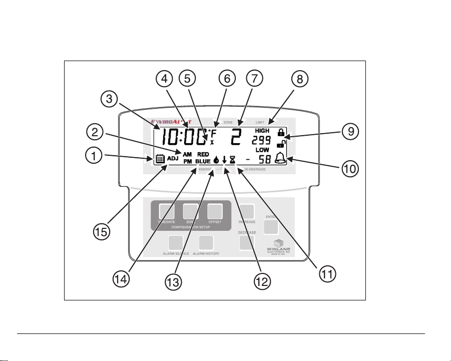
Display and Icons
Figure 4 shows and describes the display formats and icons.
Figure 4. EA200 / EA400 Display and Icons
10 D-011-0093
Display Icons
Index
No. Icon Function
1
2
3
4
5
6
7
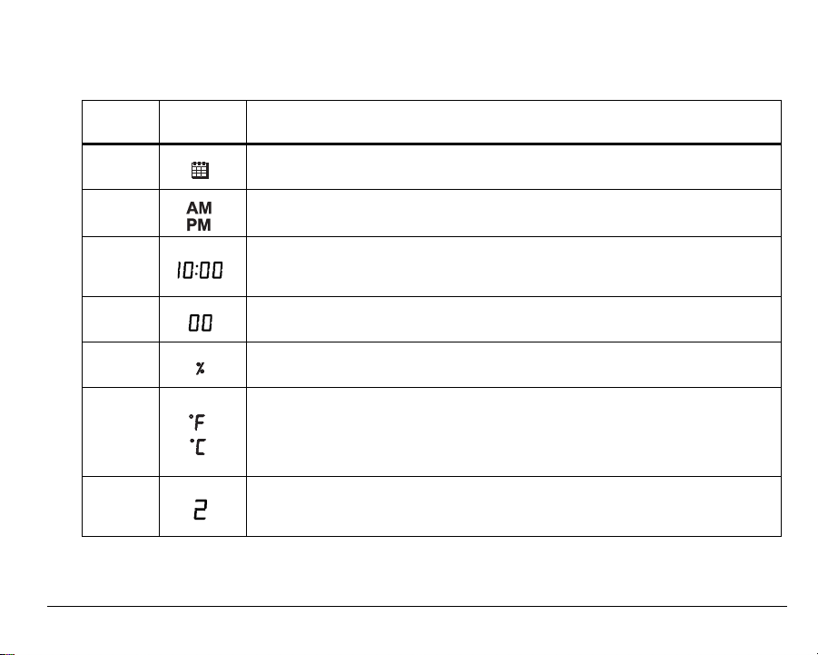
Date icon.
Indicates EA200 / EA400 Date Set mode is accessed.
Time Set display.
Indicates Time Set mode is accessed.
Time/Date/Year display.
During setup, multiple function display for setting year (4-digit), date
(month.day), and time (hours:minutes).
Temperature/Humidity display.
Displays temperature and humidity values for designated Zone.
Humidity Mode icon.
Indicates Zone is programmed for monitoring humidity.
Temperature icon.
Indicates Zone is programmed for monitoring temperature. °F or °C indicates
measurement units selection.
Running display also shows monitored temperature for Zones programmed for
temperature monitoring.
Zone display.
During programming, indicates the Zone being programmed.
Display represents active data for Zone indicated.
D-011-0093 11
Display Icons — continued
Index
No. Icon Function
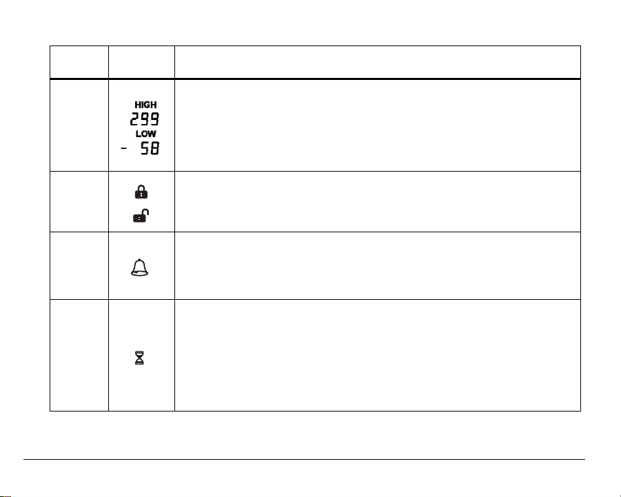
Limit display.
Shows the programmed HIGH limit and LOW limit points where measured con-
8
9
10
11
ditions exceeding limits will trigger an alarm for the related Zone.
• When programmed for temperature, the limit range allowed is between 299
degree units to –58 degree units.
• When programmed for humidity, the limit range allowed is between 100
RH% units to 0 RH% units.
Locked and Unlocked icons.
Indicates EA200 / EA400 lock status.
When EA200 / EA400 is in locked mode, programming cannot be changed; no
configuration modes are accessible.
Alarm icon.
When flashing, indicates that a Zone is in an alarm state. When steadily illumi-
nated, indicates that an alarm condition exists, but the programmed time delay
interval has not yet elapsed. When time delay period elapses, the icon will begin
flashing.
Delay Time Entry Mode icon.
During programming, indicates selection of delay time mode (up to 120 minutes
delay can be entered). When icon appears, a delay time (in minutes) can be
entered. With a delay programmed for the Zone, conditions exceeding the programmed limits (such as during a defrost cycle) are ignored for the duration of
the programmed delay.
This function is typically used to prevent false alarms for freezers and coolers
that have defrost cycles or doors that are opened frequently.
12 D-011-0093
Display Icons — continued
Index
No. Icon Function
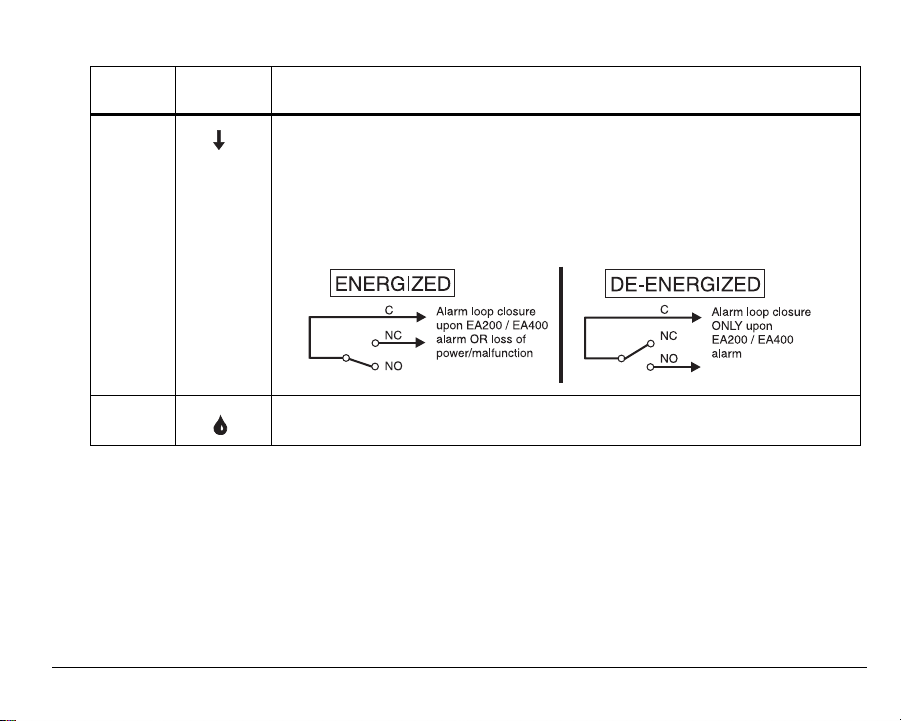
Alarm Output Relay Mode icon.
During programming, indicates selection of energized or de-energized alarm
output relay state for the Zone being programmed.
• Down arrow points to ENERGIZE when energized relay mode is selected
(relay is energized with no alarms; relay de-energizes upon alarm).
• Down arrow points to DE-ENERGIZE when de-energized relay mode is
12
selected (relay is de-energized with no alarms; relay energizes upon alarm).
13
D-011-0093 13
Water Presence Mode icon.
Indicates Zone is programmed for detecting presence of water.
Display Icons — continued
Index
No. Icon Function
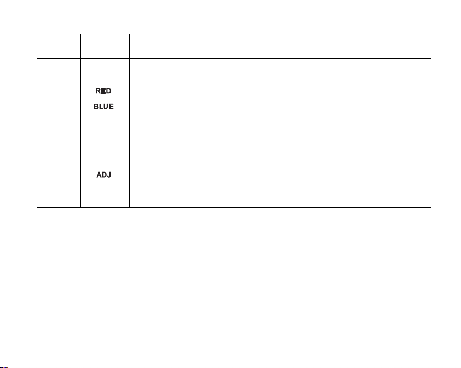
Temperature Sensor Type display.
During temperature monitoring programming, sensor type (based on conditions
expected for Zone) is entered.
14
15
• RED is selected when a “Red” (high-temperature range) sensor is to be used.
• BLUE is selected when a “Blue” (low-temperature range) sensor is to be
used.
Note: See “Accessories” on page 44 for more information regarding sensor
types and appropriate usage.
Offset Adjust icon.
Indicates that OFFSET (± 9 units) has been selected (this is selected by press-
ing the OFFSET key).
If desired, offset allows the temperature or humidity reading for the selected
Zone to be offset by a value that aligns the reading displayed on the EA200 /
EA400 with that of existing equipment, thereby correlating the EA200 / EA400
reading with that of existing equipment.
14 D-011-0093
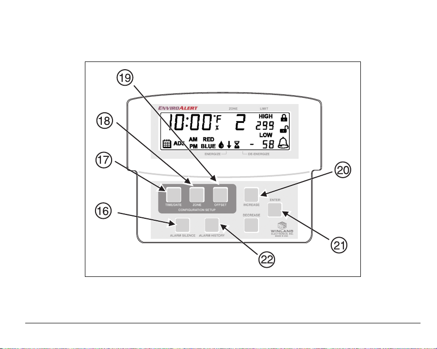
Keys
Figure 5 shows and describes the entry keys.
Figure 5. EA200 / EA400 Keys
D-011-0093 15
 Loading...