

Page 1

VHC/VHM/VHS
Vertical Hi-Rise Fan Coil
INSTALLATION, OPERATION
AND
MAINTENANCE MANUAL
Stock ID: IOM-FCUVH
April, 2002
©2002 Environmental Technologies, Inc.
Largo, FL • Part No. PX-00-0044
~
~
~
~
~
~
~
~
~
~
~
~
~
~
~
~
~
~
~
~
~
~
~
~
~
~
~
~
~
~
~
~
~
~
Page 2

VH FAN COIL • I.O.M. MANUAL
2
VH Fan Coil IOM • ©April, 2002 • Environmental Technologies, Inc.
DESCRIPTION PAGE NUMBER(S)
Important Safety Precautions . . . . . . . . . . . . . . . . . . . . . . . . . . . . . . . . . . . . . . . . . . . . . . . . 3
VH Series Features . . . . . . . . . . . . . . . . . . . . . . . . . . . . . . . . . . . . . . . . . . . . . . . . . . . . . . . 4
SECTION ONE: Receipt and Installation
Preface. . . . . . . . . . . . . . . . . . . . . . . . . . . . . . . . . . . . . . . . . . . . . . . . . . . . . . . . . . . . . . 5
Unpacking & Inspection . . . . . . . . . . . . . . . . . . . . . . . . . . . . . . . . . . . . . . . . . . . . . . . . . 6
Dimensional Data. . . . . . . . . . . . . . . . . . . . . . . . . . . . . . . . . . . . . . . . . . . . . . . . . . . . . . 7
Handling & Installation. . . . . . . . . . . . . . . . . . . . . . . . . . . . . . . . . . . . . . . . . . . . . . . . . . 8
Cooling/Heating Medium Connections . . . . . . . . . . . . . . . . . . . . . . . . . . . . . . . . . . . . . . 8
Flex Hose . . . . . . . . . . . . . . . . . . . . . . . . . . . . . . . . . . . . . . . . . . . . . . . . . . . . . . . . . . . . 9
Riser Connection . . . . . . . . . . . . . . . . . . . . . . . . . . . . . . . . . . . . . . . . . . . . . . . . . . . . . . 10
Ductwork Connections . . . . . . . . . . . . . . . . . . . . . . . . . . . . . . . . . . . . . . . . . . . . . . . . . 10
Wall Framing. . . . . . . . . . . . . . . . . . . . . . . . . . . . . . . . . . . . . . . . . . . . . . . . . . . . . . . . . 11
Outside Air Connection . . . . . . . . . . . . . . . . . . . . . . . . . . . . . . . . . . . . . . . . . . . . . . . . . 11
Electrical Connections . . . . . . . . . . . . . . . . . . . . . . . . . . . . . . . . . . . . . . . . . . . . . . . . . . 11
Thermostats . . . . . . . . . . . . . . . . . . . . . . . . . . . . . . . . . . . . . . . . . . . . . . . . . . . . . . . . . 12
Critical Penetration Areas. . . . . . . . . . . . . . . . . . . . . . . . . . . . . . . . . . . . . . . . . . . . . . . . 12
SECTION TWO: Start-Up
General. . . . . . . . . . . . . . . . . . . . . . . . . . . . . . . . . . . . . . . . . . . . . . . . . . . . . . . . . . . . . 13
Cooling/Heating System. . . . . . . . . . . . . . . . . . . . . . . . . . . . . . . . . . . . . . . . . . . . . . . . . 13
Air System Balancing . . . . . . . . . . . . . . . . . . . . . . . . . . . . . . . . . . . . . . . . . . . . . . . . . . . 13
Water System Balancing . . . . . . . . . . . . . . . . . . . . . . . . . . . . . . . . . . . . . . . . . . . . . . . . 14
Controls Operation . . . . . . . . . . . . . . . . . . . . . . . . . . . . . . . . . . . . . . . . . . . . . . . . . . . . 14
SECTION THREE: Normal Operation & Periodic Maintenance
General. . . . . . . . . . . . . . . . . . . . . . . . . . . . . . . . . . . . . . . . . . . . . . . . . . . . . . . . . . . . . 15
Motor/Blower Assembly. . . . . . . . . . . . . . . . . . . . . . . . . . . . . . . . . . . . . . . . . . . . . . . . . 15
Coil. . . . . . . . . . . . . . . . . . . . . . . . . . . . . . . . . . . . . . . . . . . . . . . . . . . . . . . . . . . . . . . . 15
Electric Resistance Heater Assembly . . . . . . . . . . . . . . . . . . . . . . . . . . . . . . . . . . . . . . . . 15
Electrical Wiring & Controls . . . . . . . . . . . . . . . . . . . . . . . . . . . . . . . . . . . . . . . . . . . . . . 16
Valves & Piping . . . . . . . . . . . . . . . . . . . . . . . . . . . . . . . . . . . . . . . . . . . . . . . . . . . . . . . 16
Filters, Throwaway . . . . . . . . . . . . . . . . . . . . . . . . . . . . . . . . . . . . . . . . . . . . . . . . . . . . 16
Drain and Drain Pan . . . . . . . . . . . . . . . . . . . . . . . . . . . . . . . . . . . . . . . . . . . . . . . . . . . 17
Replacement Parts. . . . . . . . . . . . . . . . . . . . . . . . . . . . . . . . . . . . . . . . . . . . . . . . . . . . . 17
SECTION FOUR: Inspection, Installation, & Start-Up Checklist . . . . . . . . . . . . . . . . . . . 18 - 19
Start-Up / Maintenance History. . . . . . . . . . . . . . . . . . . . . . . . . . . . . . . . . . . . . . . . . . . . . 20
Page 3

Environmental Technologies, Inc. •©April, 2002 • VH Fan Coil IOM
I.O.M. M
ANUAL • VH F
AN
COIL
3
SAFETY CONSIDERATIONS
The equipment covered by this manual is designed for safe and reliable operation when installed and operated within its design specification limits. To avoid personal injury or damage to equipment or property
while installing or operating this equipment, it is essential that qualified, experienced personnel perform
these functions using good judgement and safe practices. See the following cautionary statements.
DANGER
ELECTRICAL SHOCK HAZARDS. All power must be disconnected prior to installation and serving this equipment. More than one source of power may be present. Disconnect all power sources to avoid electrocution or shock injuries.
MOVING PARTS HAZARDS. Motor and Blower must be disconnected prior to opening access panels. Motors
can start automatically, disconnect all power and control circuits prior to servicing to avoid serious crushing or dismemberment injuries.
HOT PARTS HAZARD. Electric Resistance heating elements must be disconnected prior to servicing. Electric
Heaters may start automatically, disconnect all power and control circuits prior to servicing to avoid burns.
WARNING
Check that the unit assembly and component weights can be safely supported by rigging and lifting equipment.
All assemblies must be adequately secured during lifting and rigging by temporary supports and restraints
until equipment is permanently fastened and set in its final location.
All unit temporary and permanent supports must be capable of safely supporting the equipment's weight
and any additional live or dead loads that may be encountered. All supports must be designed to meet
applicable local codes and ordinances.
All fastening devices must be designed to mechanically lock the assembly in place without the capability
of loosening or breaking away due to system operation and vibration.
CAUTION
Secure all dampers when servicing damper, actuator or linkages. Dampers may activate automatically, disconnect control circuits or pneumatic control systems to avoid injury.
Protect adjacent flammable materials when brazing, Use flame and heat protection barriers where needed. Have fire extinguisher available and ready for immediate use.
Page 4

VH FAN COIL • I.O.M. MANUAL
4
VH Fan Coil IOM • ©April, 2002 • Environmental Technologies, Inc.
VH Series Features
NOTE: Some optional items are included with other features.
Page 5

I.O.M. MANUAL • VH FAN COIL
5
Environmental Technologies, Inc. •©April, 2002 • VH Fan Coil IOM
SECTION ONE: Receipt & Installation
PREFACE
Environmental Technologies fan coils represent a prudent investment which can, with proper installation,
operation, and regular maintenance, give trouble-free operation and long service.
Your equipment is initially protected under the manufacturer’s standard warranty; however, this
warranty is provided under the condition that the steps outlined in this manual for initial inspection, proper installation, regular periodic maintenance, and everyday operation of the equipment
be followed in detail. This manual should be fully reviewed in advance of any actual work being
done on the equipment. Should any questions arise, please contact your local Sales Representative
or the factory BEFORE proceeding.
The equipment covered by this manual is available with a vast variety of options and accessories. Consult
the approved unit submittal, order acknowledgement, and other manuals for details on the options and
accessories provided with the equipment on each project.
NO ATTEMPT SHOULD BE MADE TO HANDLE, INSTALL, OR SERVICE ANY UNIT
WITHOUT FOLLOWING SAFE PRACTICES REGARDING MECHANICAL EQUIPMENT.
• Equipment must always be properly supported. Temporary supports used during installation or service
must be adequate to hold equipment securely.
• CAUTION: All power must be disconnected before any installation or service should be attempted. More
than one power source may be supplied to a unit. Power to remote mounted control devices may not
be supplied through the unit.
• Never wear bulky or loose fitting clothing when working on any mechanical equipment. Gloves should
only be worn when required for proper protection from heat or other possible injury. Safety glasses or
goggles should always be worn when drilling, cutting, or working with chemicals such as refrigerants
or lubricants.
• CAUTION: Never pressurize any equipment beyond specified test pressures. Always pressure test with
some fluid or inert gas such as clear water or dry nitrogen on refrigeration systems to avoid possible
damage or injury in the event of a leak or component failure during testing.
• CAUTION: Always protect adjacent flammable material when welding or soldering. Use suitable health
shield material to contain sparks or drops of solder. Keep a fire extinguisher nearby.
The manufacturer assumes no responsibility for personal injury or property damage resulting from improper or unsafe practices during the handling, installation, service, or operation of any equipment.
Page 6

VH Fan Coil IOM • ©April, 2002 • Environmental Technologies, Inc.
VH FAN
COIL • I.O.M. MANUAL
6
UNPACKING & INSPECTION
All units are carefully inspected at the factory throughout the manufacturing process under a strict detailed
quality assurance program, and where possible, all major components and subassemblies are carefully tested for proper operation and verified to be in full compliance with the factory manufacturing documents.
The only exception to this being the operational testing of some customer furnished components such as
control valves and switches.
Each unit is then carefully packaged for shipment to avoid damage during normal transport and handling.
The equipment should always be stored in a dry place in the proper orientation as marked on the packaging.
All shipments are made F.O.B. factory and it is the responsibility of the receiving party to inspect the equipment upon arrival. Any obvious damage to the packaging and/or its contents should be recorded on the
bill of lading and a claim should be filed with the freight carrier.
After determining the condition of the unit‘s exterior, carefully remove each unit from the
packaging and inspect for hidden damage. At this time, check to make sure that “furnished only” items
such as switches, thermostats, etc. are accounted for. Any hidden damage should be recorded and immediately reported to the carrier and a claim filed as before. In the event a claim for shipping damage is filed,
the unit, shipping package, and all packing must be retained for physical inspection by the freight carrier. All equipment should be stored in the factory shipping package with internal packing in place until
installation.
ETI performs a series of rigorous leak tests on all of the piping installed in this equipment to ensure piping integrity. Because this equipment may be shipped with factory supplied external riser piping, it is necessary for the receiving inspector to carefully inspect this piping for signs of shipping damage. If damage
is present, a claim must be filed with the freight carrier (refer to ETI Policy # PP-LOSS-DMG).
At the time of receipt, the equipment type and arrangement should be verified against the order documents. Should any discrepancy be found, the local Sales Representative should be notified immediately so
that the proper action may be instituted. Should any question arise concerning warranty repairs, the factory must be notified BEFORE any corrective action is taken. Where local repairs or alterations can be accomplished, the factory must be fully informed as to the extent and expected cost of those repairs before work
is begun. Where factory operations are required, the factory must be contacted for authorization to return
equipment and a Return Authorization Number will be issued. Unauthorized return shipments of equipment and shipments not marked with an authorization number will be refused. In addition, the manufacturer will not accept any claims for unauthorized expenses.
SHIP LOOSE ITEMS
Several components are shipped loose for field installation. These are: thermostat, return air access panel,
return air access panel fasteners, discharge grille(s), risers (optional). These parts are shipped loose to offer
protection against shipping and job-site damage. Refer to packing slip.
Page 7
I.O.M. MANUAL • VH FAN COIL
7
Environmental Technologies, Inc. •©April, 2002 • VH Fan Coil IOM
CR
CS
DRAIN
HS
HR
DRAIN
RETURN
SUPPLY
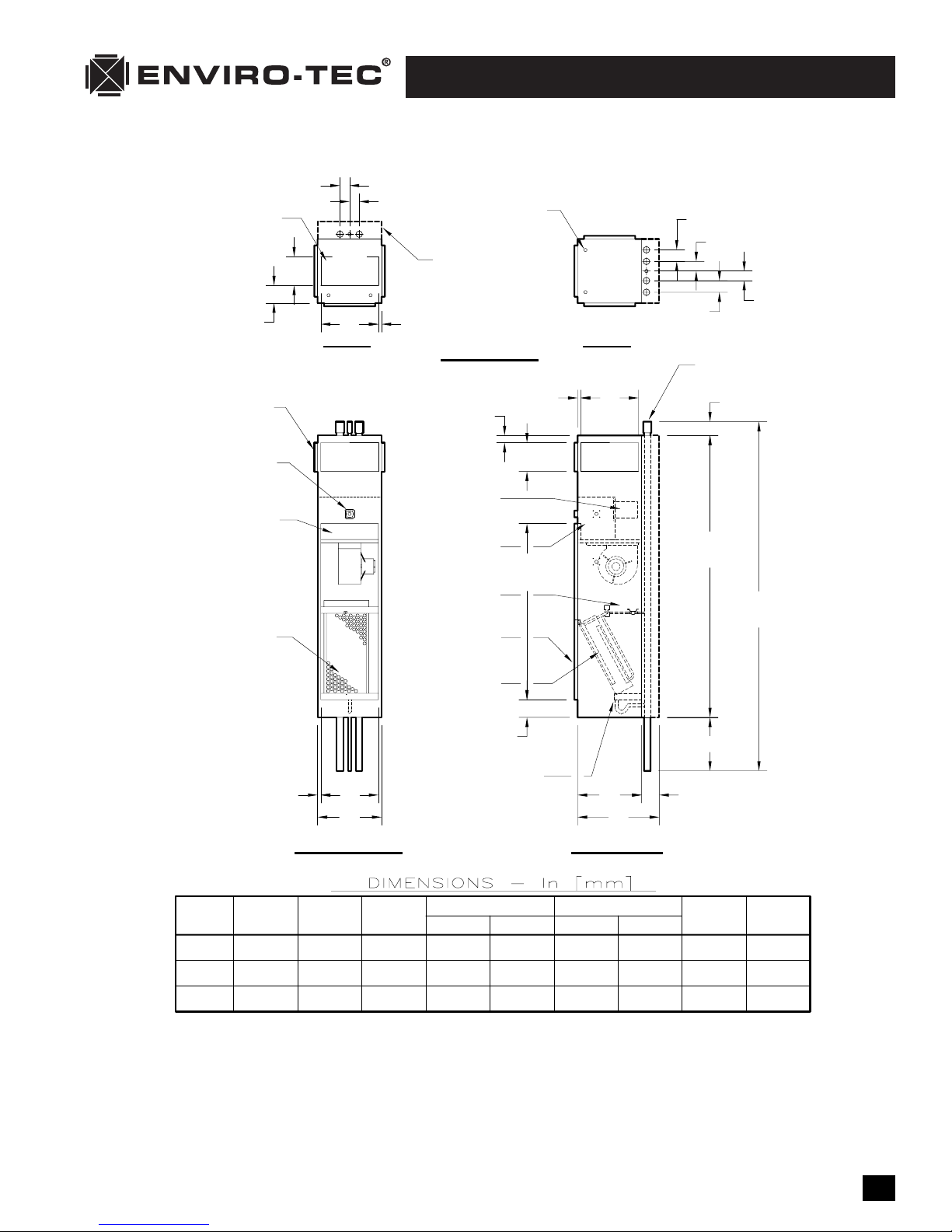
VH Series Dimensional Data • VHC Shown
3 [76]
TOP SUPPLY OPENING
WITH DUCT COLLAR,
SEE NOTES 8 & 9
F
SUPPLY AIR
OPENING(S)
WITH 5/8 [16]
DRYWALL STOP
3 [76]
DRAIN
RETURN
E
SUPPLY
D
2-PIPE
1 [25]
OPTIONAL RISER
COVER, TYP.
TOP VIEWS
ELECTRICAL ENTRY
KNOCKOUT, TYP.
2 [51]
TYP.
1 [25]
TYP.
4-PIPE
D
CR
CS
DRAIN
HR
HS
3-5/8
[92]
3-5/8
[92]
3 [76]
SWAGED RISER
JOINT, TYPICAL
3 [76]
TYP.
3 [76]
OPNG & TILE RING
FOR SURFACE MTD.
TEMP. CONTROLS
HINGED CONTROL
ENCLOSURE COVER
1 [25] TAW
FILTER
3/4 [19]
TYP.
C
A
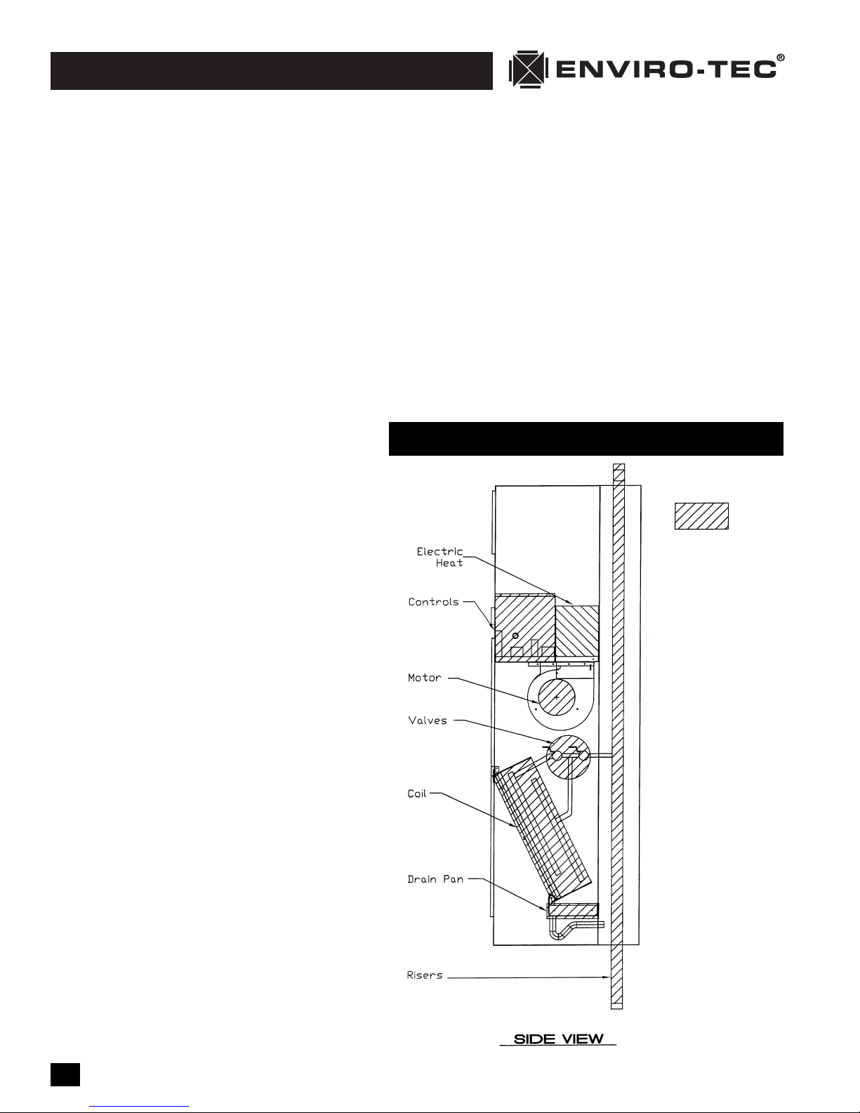
FRONT VIEW
OPTIONAL
ELECTRIC
HEAT
CONTROL
ENCLOSURE
BRAIDED HOSE
WATER PIPING
RETURN AIR &
ACCESS OPNG
WITH 5/8 [16]
DRYWALL STOP
COOLING/HEATING
COIL(S) WITH
VALVE PACKAGES
WITH "P" TRAP
5-1/2
[140]
DRAIN PAN
56-1/4
[1429]
E
88
[2235]
FLR-TO-FLR
+ 2 [51]
AS REQ'D.
A
B
5-3/8
[137]
SIDE VIEW
UNIT
SIZE
03 & 04
06 & 08
10 & 12
NOTES:
1. All dimensions are Inches [mm]. Metric values are soft conversion.
2. All dimensions are ±1/4 [6mm].
3. All drawings are subject to change without prior notice.
4. Tile ring is installed on front of unit as shown, and may be moved
to left or right side of unit in field.
5. Wiring from electrical entry point to control enclosure is
furnished and installed by others in field.
[457]
[508]
[610]
A
18
20
24
23-3/8
[594]
25-3/8
[645]
29-3/8
[746]
DOUBLE SUPPLY
16
[406]
18
[457]
22
[559]
[152]
[203]
[203]
UNIT WGT
F
ED
6
8
8
[152]
[152]
[203]
Lbs [Kg]
6
6
8
223
[101]
246
[112]
293
[133]
16-1/2
[419]
18-1/2
[470]
22-1/2
[572]
CB
SINGLE SUPPLY
16
[406]
18
[457]
22
[559]
ED
6
[152]
8
[203]
14
[356]
6. Risers available from 3/4" [19mm] to 3" [76mm] diameter with
1/2" [13mm] thick insulation, and 3/4" [19mm] to 2-1/2"
[64mm] diameter with 3/4" [19mm] thick insulation.
7. Riser length is 115" [2921mm] max, 100" [2540mm] min.
8. Back riser location shown. See arrangement drawings for
available unit configurations.
9. Size 10 and 12 top discharge is same size as double supply.
10. Unit weight includes 5 rows of coil. Risers and water weight
are not included.
Page 8

VH FAN COIL • I.O.M. MANUAL
8
VH Fan Coil IOM • ©April, 2002 • Environmental Technologies, Inc.
HANDLING & INSTALLATION
While all equipment is designed and fabricated of sturdy construction and may present a rugged appearance, great care must be taken to assure that no force or pressure be applied to the coil, risers, piping or
drain stub-outs during handling. Do not use the risers for lifting the unit. Also, depending on the options
and accessories, some units could contain delicate components that may be damaged by improper handling. Wherever possible, all units should be maintained in an upright position and handled by the exterior casing, with no impact forces applied that may damage internal components or painted surfaces.
The equipment covered in this manual IS NOT suitable for outdoor installations. The equipment should
never be stored or installed where it may be subjected to a hostile environment such as rain, snow, extreme
temperatures, or hazardous chemicals.
During and after installation, special care must be taken to prevent foreign material such as paint, plaster, and drywall dust from being deposited in the drain pan or the heater, motor and blower wheels. Failure
to do so may have serious adverse effects on unit operation and in the case of the heater, motor and blower assembly, may result in immediate or premature failure. All manufacturers’ warranties are void if foreign material is allowed to be deposited on the heater, motor or blower wheels of any unit. Some units
and/or job conditions may require some form of temporary covering during construction.
Condensate pan is internally sloped toward drain connection. Make assurance that unit is level and plumb.
Level the unit to insure proper coil operation and condensate drainage. After units are positioned and risers centered in pipe chase, make unit plumb in 2 directions, using unit frame as a reference. Avoid any
interference with wiring, coil, or coil connections, drain pain, and structural components inside the cabinet while using bolts or lag screws to anchor the unit to building. See page 12 for critical penetration
areas.
After mounting the unit, it is then ready for the various service connections such as water, drain and electrical. At this time it should be verified that the proper types of service are actually provided to the unit.
On those units requiring chilled water and/or hot water, the proper line size and water temperature should
be available to the unit. The electrical service to the unit should be compared to the unit nameplate to
verify compatibility. The routing and sizing of all piping, and the type and sizing of all wiring and other
electrical components such as circuit breakers, disconnect switches, etc. should be determined by the individual job requirements and should not be based on the size and/or type of connection provided on the
equipment. All installations should be made in compliance with all governing codes and ordinances.
Compliance with all codes is the responsibility of the installing contractor.
COOLING/HEATING MEDIUM CONNECTIONS
CAUTION: Toxic residues and loose particles resulting from manufacturing and field piping techniques
such as joint compounds, soldering flux, and metal shavings may be present in the unit and the
piping system. Special consideration must be given to system cleanliness when connecting to solar,
domestic or potable water systems.
Submittals and Product Catalogs detailing unit operation, controls, and connections should be thoroughly reviewed BEFORE beginning the connection of the various cooling and/or heating mediums to the unit.
All accessory valve packages should be installed as required, and all service valves should be checked for
proper operation.
If coil and valve package connections are to be made with “sweat” or solder joint, care should be taken
to assure that no components in the valve package are subjected to a high temperature which may damage seals or other materials. Many two-position electric control valves, depending on valve operation, are
Page 9

Environmental Technologies, Inc. •©April, 2002 • VH Fan Coil IOM
I.O.M. M
ANUAL • VH F
AN
COIL
9
provided with a manual-opening lever. This lever should be placed in the “open” position during all soldering or brazing operations. Solder joints with Silfos, phos-copper, or similar high temperature alloy. Do
not use soft solder.
If the valve package connection at the coil is made with a union or threaded fitting, the coil side of the
union or threaded fitting must be prevented from twisting (“backed up”) during tightening to prevent
damage to the coil tubing over-tightening must be avoided to prevent distorting the union seal surface
and destroying the union.
FLEX HOSE
Factory Supplied Risers:
Environmental Technologies uses Kevlar
®
reinforced braided stainless steel flexible hoses for all water piping connections between the risers and the unit. All supply and return risers are provided with a ½" ball
valve. The ball valve may be attached to the riser with either a sweat connection or a threaded connection. The hose is attached to the ball valve with either a fixed crimped connection or a threaded swivel
connection. Refer to figure below for typical piping and hose configurations. All swivel hose connections
require the use of a vulcanized fiber gasket to prevent leakage unless otherwise denoted on figure below.
All factory supplied piping including swivel connections are tightened
and pressure tested to
350 PSIG during the
manufacturing process.
See note below.
During transit, vibration
may cause a connection
to loosen. Therefore, all
threaded connections
must be checked during
unit installation. Any fitting that is loose must be
tightened. Any stationary connections must be
prevented from twisting
by the application and
use of a backup wrench
during the tightening
process. Pressure test
before applying water.
NOTE: If a hose swivel
connection is disconnected after it has been
tightened, the gasket
must be replaced.
Additional gaskets are
available from your nearest Enviro-Tec representative. The gasket part
number is PH-05-0047.
TYPICAL PIPING & HOSE CONFIGURATIONS
Page 10

VH Fan Coil IOM • ©April, 2002 • Environmental Technologies, Inc.
VH FAN
COIL • I.O.M. MANUAL
10
Field Supplied Risers:
On units with field supplied risers, the ball valve must be connected to the riser prior to connecting the
hose. All standard tapered pipe thread joints that do not have a gasket or O-ring require the use of a Teflon
®
or polyester blend pipe dope such as Rectorseal T+2®. It is necessary that a vulcanized fiber gasket be installed
in the hose's swivel fitting prior to connecting the hose. Gaskets are shipped with the unit hose assembly.
See note on page 9. Replacement gaskets are available from your Enviro-Tec representative. The gasket
part number is PH-05-0047. All mating connections must be prevented from twisting during the swivel
tightening process by using a backup wrench. Pressure test piping system before applying water.
Refer to drawing on page 9 for typical piping and hose configurations.
RISER CONNECTION
Do not rigidly fasten risers within this equipment. Riser must be free to move with thermal expansion and
contraction. Risers should accommodate as a minimum ± 1½" of vertical expansion/contraction. If total
combined riser expansion will exceed 3" (1½ x 2 = 3"), additional expansion loops or joints must be field
supplied and installed. Remove riser shipping straps prior to commissioning unit. Center coil to riser connection in its expansion slot. Some variation in building structure may necessitate cutting off or lengthening of risers; any modifications are the responsibility of the installer. Riser fire blocking is responsibility
of installer. All floor penetrations for risers should be sealed with materials rated for applicable fire resistance rating of the building.
In the case of field installed valves, riser and piping, the chilled water valve cluster and riser should be
installed in such a way that any dripping or sweating is contained in the drain pan or other device.
After the connections are completed and prior to furring-in the riser connections, the system should then
be tested for leaks. Since some components are not designed to hold pressure with a gas, hydronic systems should be tested with water.
CAUTION: Maximum unit operating pressure is 300 PSIG. Maximum unit field test pressure is 275
PSIG.
CAUTION: All water coils must be protected from freezing after initial filling with water. Even if the
system is drained, unit coils may still hold enough water to cause damage when exposed to temperatures below freezing.
In the event that leaking or defective components are discovered, the Sales Representative must be notified BEFORE any repairs are attempted. All leaks should be repaired before proceeding with installation.
After system integrity has been established, the piping should be insulated in accordance with the project
specifications. All chilled water piping and valves not located over drain pans must be insulated to prevent damage from sweating. This includes factory and field piping inside the unit cabinet. All external risers must be insulated and riser tees sloped down toward the unit coil to allow any condensate drips to
enter drain pan. The drain should always be connected and piped to an acceptable disposal point. For
proper moisture carry-off, the drain piping should be sloped away from the unit at least 1/8" per foot. A
drain trap is integral to the unit and is strongly recommended for odor containment. Avoid pinching or
kinking the drain line.
DUCTWORK CONNECTIONS
All ductwork and/or supply and return grills should be installed in accordance with the project plans and
specifications. If not included on the unit or furnished from the factory, supply and return grilles should
be provided as recommend in the product catalog.
Page 11

Environmental Technologies, Inc. •©April, 2002 • VH Fan Coil IOM
I.O.M. M
ANUAL • VH F
AN
COIL
11
All units must be installed in non-hazardous areas. Zero clearance to combustible materials is allowed.
Some models are designed to be connected to duct-work with a MINIMUM amount of external static pressure. These units may be damaged by operation without the proper duct-work connected. Consult the
approved submittals and the product catalog for unit external static pressure limitations.
Units provided with outside air for ventilation should have some form of low temperature protection to
prevent coil freeze-up. This protection may be any of several methods such as a low temperature thermostat to close the outside air damper or a preheat coil to temper the outside air before it reaches the
unit.
It should be noted that none of these methods would adequately protect a coil in the event of power failure. The safest method of freeze protection is to use glycol in the proper percent solution for the coldest
expected air temperature.
Flexible duct connections should be used on all air handling equipment. All ductwork and
insulation should be installed to allow proper access to all components for service and repair such as filters motor/blower assemblies, etc.
Dual Air Discharge Units. All dual discharge units are provided with a sight and sound baffle in the discharge plenum area (except top discharge units). It is recommended that a discharge grille with a damper
be provided in one of the discharge locations to aid in air balancing. Dual discharge units with top discharge must be provided with a field supplied damper in the top discharge duct.
The manufacturer assumes no responsibility for undesirable system operation due to improper field
design, equipment or component selection, and/or installation of ductwork, grilles, and other related components.
WALL FRAMING – All Wall Framing is the Responsibility of Others
Units are designed for field mounting of a drywall enclosure around units. Care must be exercised when
mounting framing members or drywall to units.
1. Use low profile pan head screws.
2. Do not locate screws, nails or mechanical fasteners where they can penetrate coils, risers, piping,
electrical enclosures or other components. See drawing on page 12.
3. Do not apply drywall or framing to drain pans as condensate leaks may result.
4. Do not apply drywall or framing to electrical enclosures as electrical short circuits may develop and a
potential for shock hazard may be encountered.
5. Do not apply drywall to removable access panels.
OUTSIDE AIR CONNECTION
Outside air connections are provided with a manual slide damper to balance the amount of outside air.
It is adjustable by loosening the lock nut, sliding the damper to the desired position, and tightening the
lock nut. Installation of outside air duct connections may require installation of vapor barrier between
the unit and the wall, and may require freeze control devices. These components must be supplied and
installed by the installer as required.
ELECTRICAL CONNECTIONS — CAUTION: SHOCK / ELECTRICAL HAZARDS
The unit nameplate lists the unit electrical characteristics such as the required supply voltage, fan and heater
amperage and required circuit ampacities. The unit-wiring diagram shows all unit and field wiring. Since
each project is different and each unit on a project may be different, the installer must be familiar with
the wiring diagram and nameplate on the unit BEFORE beginning any wiring. Provide for adequately sized
Page 12
VH Fan Coil IOM • ©April, 2002 • Environmental Technologies, Inc.
VH FAN
COIL • I.O.M. MANUAL
12
fused, circuit breaker or disconnect means as applicable to meet local and national electrical codes. All
electrical connections should be checked for tightness prior to startup.
All components furnished for field installation, by either the factory or the controls contractor should be
located and checked for proper function and compatibility. All internal components should be checked
for shipping damage and any loose connections should be tightened to minimize problems during startup.
Any devices such as fan switches or thermostats that have been furnished from the factory for field installation must be wired in strict accordance with the applicable wiring diagrams. Failure to do so could result
in personal injury or damage to components and will void all manufacturers’ warranties. Refer to the diagram within unit.
THERMOSTATS
Various types of thermostats are available for this unit. Unit mounted thermostats are provided with a
drywall mud ring for field mounting. The mud ring may be located on the unit front or either side as
appropriate in the field. Unit mounted thermostats are provided with a plug assembly for
easy connection. The plug is polarity conscience and connects only in one direction.
Remote thermostats must be field wired to unit's
connection points as indicated on the unit's
wiring diagram.
The fan motor(s) should never be controlled by
any wiring or device other than the factory furnished switch or thermostat/switch combination,
without factory authorization.
All field wiring should be done in accordance
with governing codes and ordinances. Any
modification of the unit wiring without factory authorization will result in voiding of all factory warranties and will nullify any agency
listings.
The manufacturer assumes no responsibility for
any damages and/or injuries resulting from
improperly field installed or wired components.
VH Critical Penetration Areas
Indicates critical
penetration area.
Do not
penetrate, drill,
screw to, or use
mechanical
fasteners in
shaded areas.
Page 13

Environmental Technologies, Inc. •©April, 2002 • VH Fan Coil IOM
I.O.M. M
ANUAL • VH F
AN
COIL
13
SECTION TWO: Start-Up
GENERAL
Before beginning any start-up operation, the start-up personnel should familiarize themselves with the
unit, options and accessories, and control sequence to understand the proper system operation. All personnel should have a good working knowledge of general start-up procedures and have the appropriate
start-up and balancing guides available for consultation.
The building must be completely finished including doors, windows, and insulation. All internal walls and
doors should be in place and in the normal position. In some cases the interior decorations and furniture
may influence overall system performance. The entire building should be as complete as possible before
beginning any system balancing.
The initial step in any start-up operation should be a final visual inspection. All equipment,
duct-work, and piping should be inspected to verify that all systems are complete and properly installed
and mounted, and that no debris or foreign articles such as paper or drink cans are left in the units or
other areas.
Each unit should be checked for loose wires, free blower wheel operation, and loose or missing access
panels or doors. Except as required during start-up and balancing operations, no fan coil units should be
operated without all the proper duct-work attached, supply and return grills in place, and all access doors
and panels in place and secure. A clean filter of the proper size and type must also be installed. Failure to
do so could result in damage to the equipment or building and furnishings, and/or void all manufacturers’ warranties.
COOLING/HEATING SYSTEM
Prior to the water system start-up and balancing, the chilled/hot water systems should be flushed to clean
out dirt and debris, which may have collected in the piping during construction. During this procedure,
all unit service valves must be in the closed position. This prevents foreign matter from entering the unit
and clogging the valves and metering devices. Strainers should be installed in the piping mains to prevent this material from entering the units during normal operation.
During system filling, air venting from the unit is accomplished by the use of the standard
manual, or optional automatic, air vent fitting installed on the coil. In the case of the manual air vent fitting, the screw should be turned counterclockwise no more than 1-½ turns to operate the air vent. Automatic
air vents may be unscrewed one turn counterclockwise to speed initial venting but should be screwed in
for automatic venting after start-up operations.
CAUTION: The air vent provided on the unit is not intended to replace the main system air vents
and may not release air trapped in other parts of the system. Inspect the entire system for potential air traps and vent those areas as required, independently. In addition, some systems may require
repeated venting over a period of time to properly eliminate air from the system.
CAUTION: Do not exceed 300 PSIG operating pressure.
AIR SYSTEM BALANCING
All ductwork must be complete and connected, and all grilles, filters, and access doors and panels must
be properly installed to establish actual system operating conditions BEFORE beginning air balancing oper-
ations.
Page 14

VH Fan Coil IOM • ©April, 2002 • Environmental Technologies, Inc.
VH FAN
COIL • I.O.M. MANUAL
14
Each individual unit and associated duct-work is a unique system with its own operating characteristics.
For this reason, air balancing is normally done by balance specialists who are familiar with all procedures
required to properly establish air distribution and fan system operating conditions. These procedures should
not be attempted by unqualified personnel. Exposed units with no duct-work do not require air balancing other than selecting the desired fan speed.
After the proper system operation is established, the actual unit air delivery and the actual fan motor amperage draw for each unit should be recorded in a convenient place for future reference such as the inspection, installation, & start-up check sheet (provided the back of this manual). Contact the Sales Representative
or the factory for additional copies of this sheet.
WATER SYSTEM BALANCING
A complete knowledge of the hydronic system, its components, and controls is essential to
proper water system balancing and this procedure should not be attempted by unqualified
personnel. The system must be complete and all components must be in operating condition BEFORE beginning water system balancing operations.
Each hydronic system has different operating characteristics depending on the devices and
controls in the system. The actual balancing technique may vary from one system to another.
After the proper system operation is established, the appropriate system operating conditions such as various water temperatures and flow rates should be recorded in a convenient place for future reference such
as the inspection, installation, & start-up check sheet, a copy of which is provided on the back of this manual. Contact the Sales Representative or the factory for additional copies of this sheet.
Before and during water system balancing, conditions may exist which can result in noticeable water noise
or undesired valve operation due to incorrect system pressures. After the entire system is balanced, these
conditions will not exist on properly designed systems.
CONTROLS OPERATION
Before proper control operation can be verified all other systems must be in proper operation. The correct water and air temperatures must be present for the control function being tested. Some controls and
features are designed not to operate under certain conditions.
A wide range of controls and electrical options and accessories may be used with the equipment covered
in this manual. Consult the approved unit submittals, order acknowledgement, and other manuals for detailed
information regarding each individual unit and its controls. Since controls and features may vary from one
unit to another, care should be taken to identify the controls to be used on each unit and their proper
control sequence. Information provided by component manufacturers regarding installation, operation,
and maintenance of their individual controls is available upon request.
Page 15
Environmental Technologies, Inc. •©April, 2002 • VH Fan Coil IOM
I.O.M. M
ANUAL • VH F
AN
COIL
15
SECTION THREE: Normal Operation & Periodic Maintenance
GENERAL
Each unit on a job will have its own unique operating environment and conditions that may dictate maintenance schedule for that unit that is different form other equipment on the job. A formal schedule of
regular maintenance and an individual unit log should be established and maintained. This will help to
achieve the maximum performance and service life of each unit on the job.
Information regarding safety precautions contained in the preface at the beginning of this manual should be followed during any service and maintenance operations.
For more detailed information concerning service operations, consult your Sales Representative or the Factory.
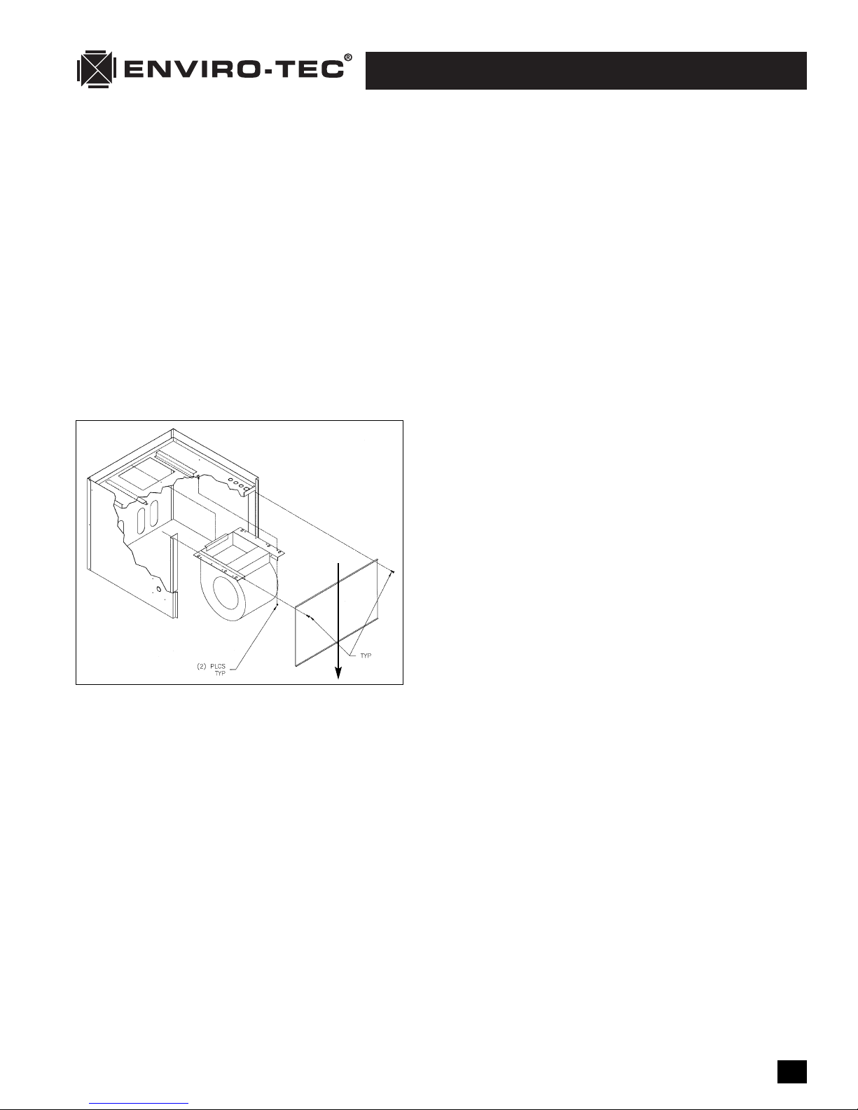
MOTOR/BLOWER ASSEMBLY
The type of fan operation is determined by the control components and their method of wiring, and may
vary from unit to unit. Refer to the wiring diagram for each unit for that unit’s individual operating characteristics. All motors have internal automatic reset thermal overloads.
Should the assembly require more extensive service, the
motor/blower assembly may be removed from the unit to
facilitate such operations as motor or blower wheel/housing replacement, etc. The motor/ blower assembly is supplied on a slide-out rail system (see drawing at left). To
remove, loosen the two lock nuts at the rack front and
slide the blower assembly out. Disconnect the motor electrical plug to fully remove the assembly from the unit. To
reinstall the blower, repeat the removal sequence in
reverse order. The rear of the blower must catch on the
support bracket supplied.
Dirt and dust should not be allowed to accumulate on the
blower wheel or housing. This can result in an unbalanced
blower wheel condition that can damage a blower wheel or motor. The wheel and housing may be cleaned
periodically using a vacuum cleaner and a brush taking care not to dislodge the factory balancing weights
on the blower wheel blades.
COIL
Coils may be cleaned by brushing the entering air face between fins with a soft brush. Brushing should
be followed by cleaning with a vacuum cleaner. If a compressed air source is available, the coil may also
be cleaned by blowing air through the coil fins from the leaving air face. Vacuuming should again follow
this procedure. Units provided with the proper type of air filters, replaced regularly, will still require periodic coil cleaning.
ELECTRIC RESISTANCE HEATER ASSEMBLY
Electric resistance heaters typically require no normal periodic maintenance when unit air filters are changed
properly. Other conditions and equipment may affect the operation and service life in the system. The two
most important operating conditions for an electric heater are proper airflow and proper supply voltage.
High supply voltage and/or poorly distributed or insufficient airflow over the element will result in element overheating. This condition may result in the heater cycling on the high limit thermal cutout. Open
coil strip heaters have an automatic reset switch with a back-up high limit thermal switch. Automatic reset
switches are as the name implies; they reset automatically after the heater has cooled down. High limit
Optional Blower
Shield
Page 16

VH Fan Coil IOM • ©April, 2002 • Environmental Technologies, Inc.
VH FAN
COIL • I.O.M. MANUAL
16
thermal switches must be replaced once the circuit has been broken. The high limit thermal cutout device
is a safety device only and is not intended for continuous operation. With proper unit application and
operation, the high limit thermal cutout will not operate. This device only operates when some problem
exists and ANY condition that causes high limit cutout MUST be corrected immediately. High supply
voltage also causes excessive amperage draw and may result in tripping of the circuit breaker or blowing
of the fuses on the incoming power supply.
After proper air flow and supply power are assured, regular filter maintenance is important to provide
clean air over the heater. Dirt that is allowed to deposit on the heating element will cause hot spots and
eventual element burn-through. These hot spots will normally not be enough to trip the thermal high limit
and may not be evident until actual heater element failure. Heaters may be serviced through the unit's
electrical section (see drawing at left). To remove heater, disconnect unit power, remove heater interconnect wiring and the fan retaining screws.
ELECTRICAL WIRING & CONTROLS
The electrical operation of each unit is determined by the components and wiring of the unit and may
vary from unit to unit. Consult the wiring diagram for the actual type and number of controls provided
on each unit.
The integrity of all electrical connections should be verified at
least twice during the first year of operation. Afterwards, all
controls should be inspected regularly for proper operation.
Some components may experience erratic operation or failure
due to age. Wall thermostats may also become clogged with
dust and lint and should be periodically inspected and cleaned
to provide reliable operation.
When replacing any components such as fuses, contactors, or
relays, use only the exact type, size, and voltage component
as furnished from the factory. Any deviation without factory
authorization could result in personnel injury or damage to the
unit and will void all factory warranties. All repair work should
be done in such a manner as to maintain the equipment in
compliance with governing codes and ordinances or testing
agency listings. More specific information regarding the use
and operating characteristics of the standard controls offered
by this manufacturer is contained in other manuals.
VALVES & PIPING
No formal maintenance is required on the valve package components most commonly used with fan coil
units other than a visual inspection for possible leaks in the course of other normal periodic maintenance.
In the event that a valve should need replacement, the same precautions taken during the initial installation to protect the valve package from excessive heat should also be used during replacement.
FILTERS, THROWAWAY
The type of throwaway filter most commonly used on fan coil units should be replaced on a regular basis.
The time interval between each replacement should be established based on regular inspection of the filter and should be recorded in the log for each unit. Refer to the product catalog for the recommended
filter size for each product type and size. If the replacement filters are not purchased from the factory,
the filters used should be the same type and size as that furnished from or recommended by the factory.
Pleated media or extended surface filters should not be used since the high air pressure drops encoun-
(6) PLCS
TYP
Page 17

Environmental Technologies, Inc. •©April, 2002 • VH Fan Coil IOM
I.O.M. M
ANUAL • VH F
AN
COIL
17
tered with these types of filters is not compatible with the type of fan coil unit covered in this manual.
Consult the factory for applications using filter types other than the factory standard or optional product. Dirty filters are the cause of the most common system performance complaints. It is essential that
filters be serviced on a reocurring regular basis.
DRAIN
The drain should be checked before initial start-up and at the beginning of each cooling season to assure
that the drain trap and line are clear. If it is clogged, steps should be taken to clear the debris so that condensate will flow easily.
Periodic checks of the drain should be made during the cooling season to maintain a free flowing condensate. Should the growth of algae and/or bacteria be a concern, consult an air conditioning and refrigeration supply organization familiar with local conditions for chemicals available to control these agents.
OPTIONAL REMOVABLE DRAIN PAN
An optional removable drain pan is available for easy ser-
vice and cleaning (see drawing at left). To remove the pan,
disconnect the drain p-trap by loosening the hose clamp
under the pan. Remove the retainer plate at the front of
the pan and slide the pan out of its track. Clean or ser-
vice pan as appropriate. Reinstall pan in reverse sequence.
Retainer plate must be installed for proper operation.
REPLACEMENT PARTS
Factory replacement parts should be used wherever pos-
sible to maintain the unit performance and operating char-
acteristics and the testing agency listings. Replacement
parts may be purchased through the local Sales Representative.
Contact the local Sales Representative or the factory before attempting any unit modifications. Any modifications not authorized by the factory could result in personnel injury and damage to the unit and could
void all factory warranties.
When ordering parts, the following information must be supplied to ensure proper part identification:
(1) Complete unit model number
(2) Unit hand connection (right or left hand) while facing into the air stream
(3) Complete part description including any numbers
On warranty replacements, in addition to the information previously listed, the project ET # that appears
on the unit nameplate, is required. Contact the factory for authorization to return any parts such as defective parts replaced in warranty. All shipments returned to the factory MUST be marked with a Return
Authorization Number, which is provided by the factory.
All equipment and components sold through the Parts Department are warranted under the same conditions as the standard manufacturer's warranty with the exception that the warranty period is 12 months
unless the component is furnished as warranty replacement. Parts furnished as warranty replacements are
warranted for the remaining term of the original unit warranties.
Page 18

VH Fan Coil IOM • ©April, 2002 • Environmental Technologies, Inc.
VH FAN
COIL • I.O.M. MANUAL
18
SECTION FOUR: Inspection, Installation & Start-Up Checklist
Receiving & Inspection
❑ Unit Received Undamaged
❑ Unit Received Complete As Ordered
❑ Unit Arrangement Correct
❑ Unit Structural Support Complete & Correct
Handling & Installation
❑ Unit Mounted Level & Square
❑ Proper Access Provided For Unit & Accessories
❑ Proper Electrical Service Provided
❑ Proper Overcurrent Protection Provided
❑ Proper Service Switch/Disconnect Provided
❑ Proper Chilled Water Line Size To Unit
❑ Proper Hot Water Line To Unit
❑ All Services To Unit In Code Compliance
❑ All Shipping Screws & Braces Removed
Cooling/Heating Connections
❑ Protect Valve Package Components From Heat
❑ Mount Valve Packages
❑ Connect Field Piping To Unit
❑ Pressure Test All Piping For Leaks
❑ Install Drain Line & Traps As Required
❑ Insulate All Piping As Required
Ductwork Connections
❑ Install Ductwork, Fittings & Grilles As Required
❑ Proper Supply & Return Grille Type & Size Used
❑ Control Outside Air For Freeze Protection
❑ Insulate All Ductwork As Required
Electrical Connections
❑ Refer To Unit Wiring Diagram
❑ Connect Incoming Power Service or Services
❑ Electrical Service of Correct Voltage and Ampacity to Support Unit Operating Loads
❑ All Field Wiring Installed With Code Compliance
❑ Check All Wiring For Secure Connections
Page 19

I.O.M. M
ANUAL • VH F
AN
COIL
19
Environmental Technologies, Inc. •©April, 2002 • VH Fan Coil IOM
Unit Start-up
❑ General Visual Unit & System Inspection
❑ Record Electrical Supply Voltage
❑ Record Ambient Temperature
❑ Close All Unit Isolation Valves
❑ Flush Water Systems
❑ Fill Systems With Water/Refrigerant
❑ Vent Water Systems As Required
❑ All Ductwork & Grilles In Place
❑ All Unit Panels & Filters In Place
❑ Start Fans, Etc.
❑ Check For Overload Condition Of All Units
❑ Check All Ductwork & Units For Air Leaks
❑ Balance Air Systems As Required
❑ Record All Final Settings For Future Use
❑ Check Piping & Ductwork For Vibration
❑ Check All Dampers For Proper Operation
❑ Verify Proper Cooling Operation
❑ Verify Proper Heating Operation
❑ Reinstall All Covers & Access Panels
Page 20

Research & Development,
Engineering, and Manufacturing.
• Variable Volume Terminals
• Fan Coil Units
• Air Handling Units
• Blower Coil Units
• Electronic Controls
6750 Bryan Dairy Rd. • Largo, FL 33777
www.enviro-tec.com
727-541-3531
©2002 Environmental Technologies, Inc.
Stock ID: IOM-FCUVH
Part No. PX-00-0044 • April, 2002
START-UP / MAINTENANCE HISTORY
Date Description
____________ __________________________________________________________________
____________ __________________________________________________________________
____________ __________________________________________________________________
____________ __________________________________________________________________
____________ __________________________________________________________________
____________ __________________________________________________________________
____________ __________________________________________________________________
____________ __________________________________________________________________
____________ __________________________________________________________________
____________ __________________________________________________________________
____________ __________________________________________________________________
____________ __________________________________________________________________
____________ __________________________________________________________________
____________ __________________________________________________________________
____________ __________________________________________________________________
____________ __________________________________________________________________
____________ __________________________________________________________________
____________ __________________________________________________________________
____________ __________________________________________________________________
____________ __________________________________________________________________
____________ __________________________________________________________________
 Loading...