

Page 1

VERTICAL HI-RISE FAN COILS SERIES B
INSTALLATION, OPERATION & MAINTENANCE
MODELS VHC/VHS/VHM VERTICAL HI-RISE
VHA/VHB TANDEM MASTER & TANDEM SLAVE
Supersedes: ET115.24-NOM4 (317) Form ET115.24-NOM4 (819)
Page 2

IMPORTANT!
READ BEFORE PROCEEDING!
GENERAL SAFETY GUIDELINES
FORM ET115.24-NOM4 (819)
This equipment is a relatively complicated apparatus.
During rigging, installation, operation, maintenance,
or service, individuals may be exposed to certain components or conditions including, but not limited to:
heavy objects, refrigerants, materials under pressure,
rotating components, and both high and low voltage.
Each of these items has the potential, if misused or
handled improperly, to cause bodily injury or death. It
is the obligation and responsibility of rigging, installation, and operating/service personnel to identify and
recognize these inherent hazards, protect themselves,
and proceed safely in completing their tasks. Failure
to comply with any of these requirements could result
in serious damage to the equipment and the property in
which it is situated, as well as severe personal injury or
death to themselves and people at the site.
This document is intended for use by owner-authorized
rigging, installation, and operating/service personnel. It
is expected that these individuals possess independent
training that will enable them to perform their assigned
tasks properly and safely. It is essential that, prior to
performing any task on this equipment, this individual
shall have read and understood the on-product labels,
this document and any referenced materials. This individual shall also be familiar with and comply with
all applicable industry and governmental standards and
regulations pertaining to the task in question.
SAFETY SYMBOLS
The following symbols are used in this document to alert the reader to specific situations:
Indicates a possible hazardous situation
which will result in death or serious injury
if proper care is not taken.
Identies a hazard which could lead to
damage to the machine, damage to other
equipment and/or environmental pollution if proper care is not taken or instructions and are not followed.
Indicates a potentially hazardous situation which will result in possible injuries
or damage to equipment if proper care is
not taken.
External wiring, unless specied as an optional connection in the manufacturer’s product line, is
not to be connected inside the control cabinet. Devices such as relays, switches, transducers and
controls and any external wiring must not be installed inside the micro panel. All wiring must be in
accordance with ENVIRO-TEC's published specications and must be performed only by a qualied
electrician. ENVIRO-TEC will NOT be responsible for damage/problems resulting from improper
connections to the controls or application of improper control signals. Failure to follow this warn-
ing will void the manufacturer’s warranty and cause serious damage to property or personal injury.
2
Highlights additional information useful
to the technician in completing the work
being performed properly.
ENVIRO-TEC
Page 3

FORM ET115.24-NOM4 (819)
CHANGEABILITY OF THIS DOCUMENT
In complying with ENVIRO-TEC's policy for continuous product improvement, the information contained
in this document is subject to change without notice.
ENVIRO-TEC makes no commitment to update or
provide current information automatically to the manual or product owner. Updated manuals, if applicable,
can be obtained by contacting the nearest ENVIROTEC Service office.
It is the responsibility of rigging, lifting, and operating/
service personnel to verify the applicability of these
documents to the equipment. If there is any question
SAFETY CONSIDERATIONS
The equipment covered by this manual is designed for
safe and reliable operation when installed, operated,
and maintained within its’ design specifications. To
avoid personal injury or damage to equipment or property during installation, operation, and maintenance of
this equipment, it is essential that these functions be
performed by qualified, experienced personnel using
good judgment and safe practices. See the following
cautionary statements.
ELECTRICAL SHOCK HAZARDS. All
power must be disconnected prior to installation and servicing of this equipment.
More than one power source may be present. Disconnect all power sources to avoid
electrocution or shock injuries.
regarding the applicability of these documents, rigging, lifting, and operating/service personnel should
verify whether the equipment has been modified and
if current literature is available from the owner of the
equipment prior to performing any work on the chiller.
CHANGE BARS
Revisions made to this document are indicated with a
line along the left or right hand column in the area the
revision was made. These revisions are to technical information and any other changes in spelling, grammar
or formatting are not included.
HOT P ARTS HAZARDS. Hot water and
steam heating coils operate at temperatures that will cause severe burn injury.
Some systems will continue to allow circulation of hot water, even with all control
circuits deenergized. Before performing
service at or near any heating coil, piping,
or valve package component, disconnect
all power and close all isolation valves,
and allow the equipment to cool. As previously mentioned, more than one power
source may be present.
Check that the unit assembly and component weights can be safely supported by
rigging and lifting equipment.
ENVIRO-TEC
MOVING PARTS HAZARDS. Power
must be disconnected from the motor and
blower prior to opening access panels.
Motors can start automatically, and more
than one power source may be present.
Disconnect all power and control circuits
prior to servicing to avoid serious crushing or dismembering injuries.
Electric resistance heating elements
may start automatically. Disconnect all
power and control circuits, and allow
the elements to cool before servicing.
Again, more than one power source may
be present.
All assemblies must be adequately secured during lifting and rigging by
temporary supports and restraints until
equipment is permanently fastened and
set in its nal location.
All unit temporary and permanent supports must be capable of safely sup-
porting the equipment’s weight and any
additional live or dead loads that may
be encountered. All supports must be
designed to meet applicable local codes
and ordinances.
3
Page 4

FORM ET115.24-NOM4 (819)
All fastening devices must be designed to
mechanically lock the assembly in place
without the capability of loosening or
breaking away due to system operation
and vibration.
Secure all dampers when servicing
damper, actuator or linkages. Dampers
may activate automatically, disconnect
control circuits to avoid injury.
Protect adjacent flammable materials
when brazing, Use ame and heat pro-
tection barriers where needed. Have re
extinguisher available and ready for immediate use.
Never wear bulky or loose tting clothing when working on any mechanical
equipment. Gloves should only be worn
when required for proper protection
from heat or other possible injury. Safety
glasses or goggles should always be
worn when drilling, cutting, or working
with chemicals such as refrigerants or
lubricants.
Never pressurize any equipment beyond
specied test pressures. Always pressure
test with some uid or inert gas such as
clear water or dry nitrogen on refrigeration systems to avoid possible damage or
injury in the event of a leak or component
failure during testing.
The manufacturer assumes no responsibility for personal injury or property
damage resulting from improper or unsafe practices during the handling, installation, service, or operation of any
equipment.
TROUBLESHOOTING REFERENCE
Component Description Guide Name Option Description
Fan Relay Board (FCRB) –
Fan Coil Relay Board (FCRB)
Fan Relay Board II (FRBii)
G3 PWM Board Fan Coil EC Motor IOM
NOTE:
All documents downloadable at www.enviro-tec.com.
Installation, Operation and
Maintenance
Fan Relay Board II (FRBii)
– Installation, Operation and
Maintenance
1st generation relay board, 24V Control
Packages, units shipped before 3/31/2017
2nd generation relay board, 24V Control
Packages
ECM controller on variable speed ECM
units
4
ENVIRO-TEC
Page 5

VH SERIES B FEATURES
SEE SECTION 6 - Dimensional Data FOR DIMENSIONAL DRAWINGS
Risers
(Optional)
FORM ET115.24-NOM4 (819)
(Optional, Shipped Loose)
Supply Air Grille
Room Thermostat
(Optional, Shipped Loose)
Incoming Power
Disconnect switch
(Optional With
Electric Heat)
Control Enclosure
Access Door
Blower Shield
(Optional)
Supply Air
Opening Knockout
Typical
Removable
Riser Chase
(Optional)
Controls
(Refer to Appropriate Relay
Board IOM if Present)
Slide Out
Blower Assembly
Deplugable
Motor
Outside Air
Inlet (optional)
Return Air/Access Panel
(Optional, Shipped Loose)
Note: Some optional items are included with
other features.
Hydronic Cooling/
Heating Coil
Air Filter
Drain Pan With "P-Trap",
Fixed Standard
(Optional Slideout)
ENVIRO-TEC
5
Page 6

FORM ET115.24-NOM4 (819)
TABLE OF CONTENTS
SECTION 1 - RECEIPT & INSTALLATION ............................................................................................................11
Preface .........................................................................................................................................................11
Unpacking & Inspection .................................................................................................................................11
Ship Loose Items ..........................................................................................................................................11
Handling & Installation ..................................................................................................................................12
Cooling/Heating Medium Connections ...........................................................................................................12
Flex Hose .....................................................................................................................................................14
Factory Installed Risers ................................................................................................................................14
Factory Furnished, Field Installed Risers .....................................................................................................15
Field Furnished and Installed Piping or Risers .............................................................................................16
Riser Connection ..........................................................................................................................................16
Ductwork Connections .................................................................................................................................17
Dual Air Discharge Units .......................................................................................................................17
Field Reconfigurable Risers and Discharge Openings ...................................................................................18
Riser Reconguration ..........................................................................................................................18
Discharge Opening Reconfiguration .............................................................................................................18
Wall Framing .................................................................................................................................................19
Tandem Master & Tandem Slave Unit Installation ........................................................................................19
Outside Air Connection .................................................................................................................................20
Manual Outside Air Damper ............................................................................................ .............................20
Motorized Outside Air Damper ............................................................................................ .........................20
Electrical Connections Shock / Electrical Hazards .........................................................................................20
Thermostats .................................................................................................................................................21
SECTION 2 - START-UP .........................................................................................................................................23
General .........................................................................................................................................................23
Cooling/Heating System ...............................................................................................................................23
Air System Balancing ...................................................................................................................................24
Water System Balancing ..............................................................................................................................24
Controls Operation .......................................................................................................................................24
Fan Coil EC Motor Control .............................................................................................................................25
G3 PWM Board .....................................................................................................................................25
PWM Board Status LED ........................................................................................................................25
G3 PWM Status Descriptions ................................................................................................................26
Adjusting EC Motor Speed ....................................................................................................................27
2 – 10 VDC Proportional Motor Control ..........................................................................................................29
EC Motor Troubleshooting Guidelines ............................................................................................................32
Checking EC Wire Harnesses ........................................................................................................................35
EC Motor and Driver .......................................................................................................................................35
Constant Airow/Constant Torque EC Motors .......................................................................................35
Constant RPM EC Motors .....................................................................................................................36
Constant RPM EC Motor Driver Enable Jumper ...................................................................................37
ECM 3-Speed Constant Torque Motor Troubleshooting Guide ......................................................................38
Procedure for Checking ECM Constant Torque Wiring Harnesses .......................................................39
ECM Constant Torque Motor Connections ............................................................................................39
ECM Constant Torque Motor Specications ..........................................................................................40
6
ENVIRO-TEC
Page 7

TABLE OF CONTENTS (CONT'D)
SECTION 3 - NORMAL OPERATION & PERIODIC MAINTENANCE ...................................................................42
General .........................................................................................................................................................42
Motor/Blower Assembly ................................................................................................................................42
Coil .................................................................................................................................................................42
Electric Resistance Heater Assembly .............................................................................................................42
Electrical Wiring & Controls ..........................................................................................................................43
Valves & Piping .............................................................................................................................................43
Filters, Throwaway .......................................................................................................................................44
Drain .............................................................................................................................................................44
Optional Removable Drain Pan ....................................................................................................................44
Replacement Parts .......................................................................................................................................44
SECTION 4 - INSPECTION, INSTALLATION & START-UP CHECKLIST .............................................................46
SECTION 5 - TROUBLESHOOTING ......................................................................................................................48
SECTION 6 - DIMENSIONAL DATA .......................................................................................................................51
Vertical Hi-Rise Tandem Units
VHA/VHB Installation Instructions ..................................................................................................................75
Receipt & Initial Installation ...................................................................................................................75
Temperature ...................................................................................................................................................79
FORM ET115.24-NOM4 (819)
ENVIRO-TEC
7
Page 8

FORM ET115.24-NOM4 (819)
LIST OF FIGURES
FIGURE 1 - Flex Hose Connections .....................................................................................................................13
FIGURE 2 - Ball Valve With Memory Stop............................................................................................................13
FIGURE 3 - Factory Installed Risers ....................................................................................................................14
FIGURE 4 - Factory Installed Risers, Master/Slave Conguration .......................................................................15
FIGURE 5 - Factory Furnished, Field Installed Risers .........................................................................................15
FIGURE 6 - Factory Furnished, Field Installed Risers, Master/Slave ..................................................................15
FIGURE 7 - Field Furnished and Installed Risers ................................................................................................16
FIGURE 8 - Field Furnished and Installed Risers Master/Slave ..........................................................................16
FIGURE 9 - Knockout Removal ............................................................................................................................18
FIGURE 10 - Critical Penetration Areas .................................................................................................................19
FIGURE 11 - Outside Air Connection .....................................................................................................................20
FIGURE 12 - G3 PWM Board .................................................................................................................................25
FIGURE 13 - Program Mode (Conguration Switch 1 ON) ....................................................................................26
FIGURE 14 - Constant RPM and Constant Torque EC Motors Example Fan Calibration Curve ...........................27
FIGURE 15 - Constant Airow and Constant Torque EC Motors Example Fan Calibration Curve ........................27
FIGURE 16 - High Speed Adjust ............................................................................................................................28
FIGURE 17 - Medium Speed Adjust .......................................................................................................................28
FIGURE 18 - Low Speed Adjust .............................................................................................................................29
FIGURE 19 - Normal Three Speed Operation ........................................................................................................29
FIGURE 20 - Mode to 2–10 VDC Proportional Control ..........................................................................................30
FIGURE 21 - Max Speed Adjust .............................................................................................................................30
FIGURE 22 - Min Speed Adjust ..............................................................................................................................31
FIGURE 23 - Normal 2 – 10 VDC Speed Control ...................................................................................................31
FIGURE 24 - Constant CFM/Constant Torque EC Motors (1/3 HP Shown) ...........................................................35
FIGURE 25 - Constant CFM/Constant Torque EC Motor Driver.............................................................................35
FIGURE 26 - Constant RPM EC Motor (1/4 HP Shown) ........................................................................................36
FIGURE 27 - Constant RPM EC Motor Driver ........................................................................................................36
FIGURE 28 - Constant RPM EC Driver EC Motor Enable Connector ....................................................................37
FIGURE 29 - Motor Power and Signal Connectors ................................................................................................39
FIGURE 30 - Motor/Blower Assembly ....................................................................................................................42
FIGURE 31 - Electric Heat .....................................................................................................................................43
FIGURE 32 - Drain Pan Removal ...........................................................................................................................44
FIGURE 33 - Model VHM, Vertical Concealed Master High Rise, FCU, 88" Cabinet ............................................51
FIGURE 34 - Model VHS, Vertical Concealed Slave High Rise, FCU, 88" Cabinet ...............................................52
FIGURE 35 - Model VHA/VHB, Vertical Hi-Rise Tandem Fire Rated and Non-Fire Rated, FCU Combinations,
88" Cabinets .....................................................................................................................................53
FIGURE 36 - Model VH, Vertical Concealed High Rise Fan Coil Unit with 79" Cabinet .........................................55
FIGURE 37 - Model VHM, Vertical Concealed Master High Rise Fan Coil Unit with 79" Cabinet ..........................56
FIGURE 38 - Model VHS, Vertical Concealed Slave High Rise Fan Coil Unit with 79" Cabinet ............................57
FIGURE 39 - Model VHA/VHB, Vertical Hi-Rise Fire Rated and Non-Fire Rated FCU Combinations,
79" cabinets ......................................................................................................................................58
FIGURE 40 - Model VH, Vertical High Rise Coil Unit, Aluminum Discharge Grille .................................................60
FIGURE 41 - Model VHC/VHM/VHA Vertical High Rise Fan Coil Unit Arrangement Designations ........................61
FIGURE 42 - Model VHC w/o Risers & VHS/VHB Vertical High Rise Fan Coil Units, Unit Arrangement
Designations .....................................................................................................................................62
FIGURE 43 - Model VH Vertical High Rise Coil Unit Outside Inlet Dimensions .....................................................62
FIGURE 44 - Model VHM/VHA/VHC Tandem Master & Tandem Slave Unit Conguration Fan Coil Unit ..............64
8
ENVIRO-TEC
Page 9

LIST OF FIGURES (CONT'D)
FIGURE 45 - Assembly Instructions Return Panel with Latches, Quick Opening or Tamper Proof,
Model VHC/VHM/VHS High Rise FCU .............................................................................................65
FIGURE 46 - Preparation Instructions for Model VHC/VHM Vertical High Rise FCU "Ship Loose"
Riser Assemblies ..............................................................................................................................66
FIGURE 47 - Full Louvered Aluminum Return Air/Wall Panel Model VH Vertical High Rise Fan Coil Unit ............67
FIGURE 48 - Model VH Vertical High Rise Fan Coil Unit Standard Surface Mount Wall Panel .............................68
FIGURE 49 - Recessed Wall Panel Model VH Vertical High Rise Fan Coil Unit ....................................................69
FIGURE 50 - Model VH Vertical High Rise Fan Coil Unit Standard Return Wall Panel with ADA Thermostat .......70
FIGURE 51 - Suggested Riser Floor Openings VHC & VHM .................................................................................73
FIGURE 52 - Riser Terminology, Model VHC, VHM, VHA Units .............................................................................74
FIGURE 53 - Standard Installation .........................................................................................................................76
FIGURE 54 - Alternate Installation .........................................................................................................................76
FIGURE 55 - Mounting Details ...............................................................................................................................77
FORM ET115.24-NOM4 (819)
LIST OF TABLES
TABLE 1 - G3 Status LED Definition ....................................................................................................................25
TABLE 2 - EC Motor Troubleshooting Guidelines ................................................................................................32
TABLE 3 - Signal Connector ................................................................................................................................36
TABLE 4 - Power Connector ................................................................................................................................36
TABLE 5 - CON1, Power Input ............................................................................................................................36
TABLE 6 - CON502 (if present), Programming Connector ..................................................................................36
TABLE 7 - CON302, PWM Signal Input ...............................................................................................................36
TABLE 8 - CON503 (if present), Motor Enable Input ...........................................................................................37
TABLE 9 - CON202, Feedback from EC Motor Hall Sensor ................................................................................37
TABLE 10 - CON201, Output Power to Motor .......................................................................................................37
TABLE 11 - ECM Constant Torque Motor Specific Troubleshooting Guidelines ....................................................38
TABLE 12 - The ECM Constant Torque Motor Power Wiring Harness ..................................................................39
TABLE 13 - The Standard ECM Constant Torque Motor Signal Wiring Harness (White Plug) ..............................40
TABLE 14 - The High Static ECM Constant Torque Motor Signal Wiring Harness (Red Plug) ..............................40
TABLE 15 - ECM Constant Torque Motor Part Numbers .......................................................................................40
TABLE 16 - Motor Signal Tap Specifications..........................................................................................................40
TABLE 17 - General ECM Constant Torque Motor Specifications .........................................................................40
TABLE 18 - Discharge Register Performance Data, VH Standard FCU 88" Cabinet,
Single and Double Supply ..................................................................................................................71
TABLE 19 - Discharge Register Performance Data, VH Standard FCU 79" Cabinet,
Single and Double Supply ..................................................................................................................72
TABLE 20 - SI Metric Conversion ..........................................................................................................................79
ENVIRO-TEC
9
Page 10

FORM ET115.24-NOM4 (819)
THIS PAGE INTENTIONALLY LEFT BLANK
10
ENVIRO-TEC
Page 11

FORM ET115.24-NOM4 (819)
SECTION 1 - RECEIPT & INSTALLATION
PREFACE
ENVIRO-TEC
ment which can, with proper installation, operation,
and regular maintenance, give trouble-free operation
and long service.
Equipment is initially protected under the manufacturers’ standard warranty; however, this warranty is
provided under the condition that the steps outlined in
this manual for initial inspection, proper installation,
regular periodic maintenance, and everyday operation
of the equipment be followed in detail. This manual
should be fully reviewed in advance of any actual work
being done on the equipment. Should any questions
arise, please contact your local Sales Representative or
the factory BEFORE proceeding.
The equipment covered by this manual is available
with a vast variety of options and accessories. Consult
the approved unit submittal, order acknowledgement,
and other manuals for details on the options and accessories provided with the equipment on each project.
UNPACKING & INSPECTION
All units are carefully inspected at the factory throughout the manufacturing process under a detailed quality assurance program. All factory furnished major
components and subassemblies are carefully tested for
proper operation and verified to be in full compliance
with the customer order and quality assurance documents.
Each unit is then carefully packaged for shipment to
avoid damage during normal transport and handling.
The equipment must be stored in a dry place in the
proper orientation as marked on the packaging.
All shipments are made F.O.B. factory and it is the
responsibility of the receiving party to inspect the
equipment upon arrival. Any obvious damage to the
packaging and/or its contents should be recorded on
the bill of lading and a claim should be filed with the
freight carrier.
fan coils represent a prudent invest-
1
After determining the condition of the unit’s exterior,
carefully remove each unit from the packaging and inspect for hidden damage. At this time, check to make
sure that “ship loose” items such as grilles, decorator
panels, and thermostats are accounted for. Any hidden
damage should be recorded and immediately reported
to the carrier, and a claim filed as before. In the event
a claim for shipping damage is filed, the unit, shipping
package, and all packing must be retained for physical
inspection by the freight carrier. All equipment should
be stored in the factory shipping package with internal
packing in place until installation.
A series of rigorous leak tests are performed on all of
the piping installed in this equipment to ensure piping
integrity . Because this equipment may be shipped with
factory supplied external riser piping, it is necessary
for the receiving inspector to carefully inspect this piping for signs of shipping damage. If damage is present,
a claim must be filed with the freight carrier.
At the time of receipt, the equipment type and arrangement should be verified against the order documents.
Should any discrepancy be found, the local Sales Representative should be notified immediately so that the
proper action may be instituted. Should any question
arise concerning warranty repairs, the factory must
be notified BEFORE any corrective action is taken.
Where local repairs or alterations can be accomplished,
the factory must be fully informed as to the extent and
expected cost of those repairs before work is begun.
Where factory operations are required, the factory must
be contacted for authorization to return equipment and
a Return Authorization Number will be issued. Unauthorized return shipments of equipment and shipments
not marked with an authorization number will be refused. In addition, the manufacturer will not accept any
claims for unauthorized expenses.
SHIP LOOSE ITEMS
Several components are shipped loose for field installation. These may include: thermostat, return air access panel, return air access panel fasteners, discharge
grille(s), risers (optional). These parts are shipped
loose to offer protection against shipping and job-site
damage. Refer to packing slip.
ENVIRO-TEC
11
Page 12

FORM ET115.24-NOM4 (819)SECTION 1 - RECEIPT & INSTALLATION
HANDLING & INSTALLATION
While all equipment is designed and fabricated of
sturdy construction and may present a rugged appear-
ance, great care must be taken to assure that no force
or pressure be applied to the coil, risers, piping or drain
stub-outs during handling. Do not use the risers for lift-
ing the unit. Also, depending on the options and acces-
sories, some units could contain delicate components
that may be damaged by improper handling. Wherever
possible, all units should be maintained in an upright
position and handled by the exterior casing, with no
impact forces applied that may damage internal com-
ponents or painted surfaces.
The equipment covered in this manual IS NOT suit-
able for outdoor installations. The equipment should
never be stored or installed where it may be subjected
to a hostile environment such as rain, snow, extreme
temperatures, or hazardous chemicals.
During and after installation, special care must be tak-
en to prevent foreign material such as paint, plaster,
and drywall dust from being deposited in the drain pan,
electric heater, motor and blower wheels. Failure to do
so may have serious adverse effects on unit operation
and in the case of the heater, motor and blower assem-
bly, may result in immediate or premature failure. All
manufacturers’ warranties are void if foreign material
is allowed to be deposited on the heater, motor or blow-
er wheels of any unit. Some units and/or job conditions
may require some form of temporary covering during
construction.
compatibility. The routing and sizing of all piping,
and the type and sizing of all wiring and other electrical components such as circuit breakers, disconnect
switches, etc. should be determined by the individual
job requirements and should not be based on the size
and/or type of connection provided on the equipment.
All installations should be made in compliance with all
governing codes and ordinances. Compliance with all
codes is the responsibility of the installing contractor.
Any new field connections must ensure all openings
are sealed and properly insulated. Improper sealing
or insulation can result in untreated air infiltrating the
unit. Units are not internally thermally isolated, proper
thermal breaks required at installation to prevent adverse effects.
For seismic certied installation, reference the seismic installation document.
COOLING/HEATING MEDIUM CONNECTIONS
Toxic residues and loose particles result-
ing from manufacturing and eld piping
techniques such as joint compounds,
soldering ux, and metal shavings may be
present in the unit and the piping system.
Special consideration must be given to
system cleanliness when connecting to
solar, domestic or potable water systems.
Condensate pan is internally sloped toward drain con-
nection. Make assurance that unit is level and plumb.
Level the unit to insure proper coil operation and con-
densate drainage. After units are positioned and risers
centered in pipe chase, plumb the unit in two directions,
using unit casing as a reference. Avoid any interference
with wiring, coil, or coil connections, drain pain, and
structural components inside the cabinet while using
bolts or lag screws to anchor the unit to building. See
Figure 10 on page 19 for critical penetration areas.
After mounting the unit, it is then ready for the various
service connections such as water, drain and electri-
cal. At this time it should be verified that the proper
types of service are actually provided to the unit. On
those units requiring chilled water and/or hot water,
the proper line size and water temperature should be
available to the unit. The electrical service to the unit
should be compared to the unit nameplate to verify
12
Submittals and Product Catalogs detailing unit operation, controls, and connections should be thoroughly
reviewed BEFORE beginning the connection of the
various cooling and/or heating mediums to the unit.
All accessory valve packages should be installed as required, and all service valves should be checked for
proper operation.
If coil and valve package connections are made with
“sweat” or solder joint, care should be taken to assure
that no components in the valve package are subjected
to a high temperature which may damage seals or other
materials. Many two-position electric control valves,
depending on valve operation, are provided with a
manual-opening lever. This lever should be placed in
the “open” position during all soldering or brazing op-
®
erations. Solder joints with Sil-fos
, phos-copper, or
similar high temperature alloy. Do not use soft solder.
ENVIRO-TEC
Page 13

SECTION 1 - RECEIPT & INSTALLATIONFORM ET115.24-NOM4 (819)
BRAIDED FLEX HOSE
P/N-PC-00-0283
3/4" FEMALE SWIVEL
MEMORY STOP
1/2" SWEAT
TO
RISER
UNIT ISOLATION
BALL VALVE P/N
PC-00-0282
2-5/8" MINIMUM
RECOMMENDED RADIUS
GASKET P/N
PH-05-0047 OR
PH-05-0048
ADAPTER FITTING
P/N PR-04-0108
TO
COIL
1/2"
FEMALE
SWIVEL
VITON O-RING
P/N PR-07-0115
3/4" NPSH
FIG. 2C
TOP VIEW
TO REGULATE FLOW (FIG. 2C):NOTE:
Valve package isolation valve shown,
typical for riser shut off valve.
FIG. 2B
TOP VIEW
FIG. 2A
EXPLODED VIEW
TO DESIRED FLOW
MEMORY STOP ADJUSTED
VALVE HANDLE WITH
"EAR" (BOTH SIDES)
MEMORY STOP
"EARS"
MEMORY STOP
ADJUSTMENT RANGE
MEMORY STOP
STEP 1. SET VALVE TO DESIRED FLOW.
STEP 4. TIGHTEN SCREW AT TOP OF VALVE.
STEP 3. TURN MEMORY STOP TO "EAR" ON VALVE BODY.
STEP 2. LOOSEN SCREW AT THE TOP OF VALVE.
1
LD13870
FIGURE 1 - FLEX HOSE CONNECTIONS
FIGURE 2 - BALL VALVE WITH MEMORY STOP
ENVIRO-TEC
LD13871
13
Page 14

FLEX HOSE
RISERS
INSTALLED
FACTORY
TYPICAL
REMOVE STRAP,
SHIPPING BRACKET,
FORM ET115.24-NOM4 (819)SECTION 1 - RECEIPT & INSTALLATION
All Vertical Hi-Rise and Tandem Master & Tandem
Slave units use Kevlar reinforced braided stainless
steel flexible hoses for all water piping between the
coil and the risers or field piping. This factory piping
includes two ball valves per coil, with memory stop.
These hoses are designed with swivel connections on
both ends, and require either a gasket or O-ring for
positive sealing. See Figure 1 on page 13 for connection details.
These hoses are designed to provide for riser movement due to thermal expansion, and allow for quick,
easy coil removal through the use of the swivel connections.
During transit, vibration may cause a connection to
loosen. Therefore, all threaded connections must be
checked during unit installation. Any fitting that is
loose must be tightened. The stationary side of any
swivel connection must be prevented from twisting
during tightening by the use of a “backup” wrench.
Pressure test all joints before applying water.
Some hose-to-coil joints are furnished
with a removable vulcanized ber gasket.
This gasket (Part No. PH-05-0047) must
be replaced each time the joint is broken.
Later model units have a hose-to-coil
joint with a black EDPM gasket (Part No.
PH-05-0048). This gasket is re-useable,
but may be replaced should it become
damaged and no longer seal.
Units provided with factory installed drain risers are
supplied with “full height” drain risers that extend
3” above the top of the unit, and include the standard
“swaged” section at the top. Field piping and venting
of the drain riser must be furnished and installed by
others.
Factory installed risers are strapped to the unit for shipment to prevent damage during transit. These shipping
straps must be removed at installation to allow movement of the risers to assure proper alignment.
See Figure 3 on page 14 and Figure 4 on page 15
for details.
At no time should a unit be lifted, moved,
or otherwise handled by the risers.
FACTORY INSTALLED RISERS
Units provided with factory installed water and drain
risers include fully insulated risers as specified per order. The flex hose and ball valve described above is
assembled to the riser and pressure tested at the factory. Each unit is configured for a specific location in
the building, and is marked with that location by room
number, floor, riser number, or other identification as
specified per order.
14
LD13872
FIGURE 3 - FACTORY INSTALLED RISERS
ENVIRO-TEC
Page 15

VITON O-RING
P/N PR-07-0115
HOSE CLAMP
SHIPPED
LOOSE
RISERS
FIGURE 4 - FACTORY INSTALLED RISERS,
MASTER/SLAVE CONFIGURATION
FACTORY FURNISHED, FIELD INSTALLED
RISERS
Units provided with factory furnished, field installed
water and drain risers include fully insulated risers as
specified per order, which are shipped separately for
installation on the job prior to receipt of the units. The
ball valve previously described is assembled to the riser
and pressure tested at the factory. The risers are packaged as a “kit” for a specific location in the building,
and each “kit” is marked with that location by room
number, floor, riser number, or other identification as
specified per order.
Riser “kits” that include drain risers are supplied with
“full height” drain risers that extend 3” above the top
of the unit, and include the standard “swaged” section
at the top, similar to factory installed riser sets. Field
piping and venting of the drain riser must be furnished
and installed by others.
Master Unit
(Model VHM)
SHIPPING BRACKET,
REMOVE STRAP,
TYPICAL
FIELD PIPING EXCEPT
ENVIRO-PAC UNITS
HOSE
CLAMP
Slave Unit
(Model VHS)
TM
LD13873
SECTION 1 - RECEIPT & INSTALLATIONFORM ET115.24-NOM4 (819)
FIGURE 5 - FACTORY FURNISHED, FIELD
INSTALLED RISERS
VITON O-RING,
P/N PR-07-0115
FIELD
FURNISHED &
INSTALLED
PIPING
SHIPPED
LOOSE
RISERS
HOSE
CLAMP
MASTER UNIT
(MODEL VHM)
VITON O-RING,
P/N PR-07-0115
HOSE
CLAMP
SLAVE UNIT
(MODEL VHS)
FIGURE 6 - FACTORY FURNISHED, FIELD
INSTALLED RISERS, MASTER/SLAVE
1
LD13866
LD13867
See Figure 5 on page 15 for details.
ENVIRO-TEC
Field installed risers MUST be installed
with the proper unit connection height
and orientation to allow for correct unit
installation at a later date. Swage is always
oriented up. Refer to unit dimensional
drawings.
15
Page 16

FIELD FURNISHED AND INSTALLED PIPING
& INSTALLED RISERS
FIELD FURNISHED
HOSE
CLAMP
HOSE
CLAMP
OR RISERS
Units provided for field furnished and installed water
and drain piping or risers include the flex hose and ball
valve assemblies previously described. These hose
and valve assemblies include a stub of copper tube for
field connection to the unit piping. The factory hose
and valve assemblies are marked by connection type
and retracted inside the unit for shipment. Do not braze
the pipe stub without opening the ball valve and disconnecting the hose. Riser stub out should slope down
slightly away from the riser. This prevents condensation from dripping at the bottom of a riser column.
See Figure 7 on page 16 for details.
Field fabricated/installed piping and risers MUST be installed with the proper
unit connection height and orientation to
allow for correct unit installation at a later
date. Refer to unit dimensional drawings.
RISER CONNECTION
Do not rigidly attach risers to this equipment. Risers
must be free to move with thermal expansion and contraction. Units and risers are designed to accommodate
a maximum of 3” (1-1/2” up and 1-1/2” down) total
vertical movement. To achieve this range of movement, the risers must be installed according to the
conditions outlined below. If the total combined riser
expansion will exceed 3”, additional expansion compensation, such as loops and expansion joints, or alternate riser anchoring techniques must be field furnished
and installed.
FORM ET115.24-NOM4 (819)SECTION 1 - RECEIPT & INSTALLATION
FIELD
FURNISHED
& INSTALLED
RISERS
HOSE
CLAMP
LD13874
FIGURE 7 - FIELD FURNISHED AND INSTALLED
RISERS
Factory furnished risers are designed with a “swage”
or socket in the top to accommodate 2” of tailpiece
insertion from the riser above. The riser configuration,
when combined with the required length as provided
by the customer, is designed to position the riser-tounit stub out piping at the vertical center of the riser
slot in the unit casing. See unit submittal drawings for
dimensional details. Due to building construction variations, some risers may require cutting or lengthening
to correctly position the riser. Any field modifications
are the responsibility of the installer.
16
LD13875
FIGURE 8 - FIELD FURNISHED AND INSTALLED
RISERS MASTER/SLAVE
ENVIRO-TEC
Page 17

SECTION 1 - RECEIPT & INSTALLATIONFORM ET115.24-NOM4 (819)
After all connections are completed, and prior to insulating and furring-in of any riser or piping connections,
the system should be tested for leaks. Since some components are not designed to hold pressure with a gas,
hydronic systems should be tested with clear water.
Care should be taken to completely drain the system,
or otherwise protect it from freezing in cold weather.
Standard unit operating pressure is 300
psig maximum. Field test pressure must
not exceed 400 psig maximum. Some optional or special unit piping components
may have lower pressure ratings than the
standard unit. All valve and piping com-
ponent pressure ratings must be veried
before applying test pressure to the unit.
All water coils and unit piping must be
protected from freezing after initial lling
with water. Unit coils and piping may still
hold enough water to cause damage when
exposed to freezing temperatures, even
after the system is drained.
In the event that leaking or defective components are
discovered, the Sales Representative must be notified
BEFORE any repairs are attempted. All leaks should
be repaired before proceeding with installation.
After all risers and piping are installed and pressure
tested, all riser joints must have the insulation joint
sealed and all other piping must be insulated in compliance with the project specifications. All chilled water
risers, piping, and valves must be insulated or located
over a drain pan, to prevent damage from condensation. This includes factory and field piping inside the
unit cabinet.
The drain should always be connected and piped to an
acceptable disposal point. For proper moisture carryoff, the drain piping should be sloped away from the
unit at least 1/8” per foot. A drain trap is integral to the
unit and is necessary for odor containment. The drain
riser and piping must be installed to avoid pinching or
kinking the unit drain tube.
Any required piping or riser penetration fire blocking
is the responsibility of the installer. All penetrations for
piping and risers should be sealed with materials and
techniques suitable for all governing codes and ordinances.
DUCTWORK CONNECTIONS
1
All ductwork and/or supply and return grills should
be installed in accordance with the project plans and
specifications. If not included on the unit or furnished
from the factory, supply and return grilles should be
provided as recommend in the product catalog.
All units must be installed in non-hazardous areas.
Zero clearance to combustible materials is allowed.
Units provided with outside air for ventilation should
have some form of low temperature protection to prevent coil freeze-up. This protection may be any of several methods such as a low temperature thermostat to
close the outside air damper or a preheat coil to temper
the outside air before it reaches the unit. It is recommended that outside air is pretreated to regulate its
temperature and humidity ratio
It should be noted that none of these methods would
adequately protect a coil in the event of power failure.
The safest method of freeze protection is to use glycol
in the proper percent solution for the coldest expected
air temperature.
Flexible duct connections should be used on all air handling equipment. All ductwork and insulation should
be installed to allow proper access to all components
for service and repair such as filters motor/blower assemblies, etc.
Dual Air Discharge Units
All dual discharge units are provided with a sight and
sound baffle in the discharge plenum area (except top
discharge units). It is recommended that a discharge
grille with a damper be provided in one of the discharge locations to aid in air balancing. Dual discharge
units with top discharge must be provided with a field
supplied damper in the top discharge duct.
Do not inhibit inlet or outlet connections.
Quickly turning off the inlet or rapid
reduction in ductwork can cause system
effects that impact airow. Reductions
in airow can cause electric heaters to
overheat, condensation to form, or other
unintended consequences, which can result in injury, property damage, equipment
damage, as well as void factory warranty.
ENVIRO-TEC
17
Page 18

FORM ET115.24-NOM4 (819)SECTION 1 - RECEIPT & INSTALLATION
INSULATION
SLIT CABINET
AS REQ'D
CLIP "TABS"
AS
REQ'D
CLIP
"TABS"
AS REQ'D
DRYWALL
STOP
FOLD OUT
FIELD RECONFIGURABLE RISERS AND
DISCHARGE OPENINGS
Riser Reconfiguration
Vertical Hi-Rise units are furnished with riser slot
“knockouts” in the casing back and both sides. Should
it be necessary to relocate risers in the field, the water
risers may be disconnected at the swivel joint on the
riser isolation valve, and removed from the unit. The
drain riser may be removed by moving the drain tube
hose clamp and removing the riser tube from the drain
hose.
The water riser slot “knockouts” may be removed by
clipping the “tabs” to separate the inner portion of the
knockout. See Figure 9 on page 18 for details. After
opening the riser slot, make a vertical slit in the cabinet
insulation with a sharp utility knife. This slit must be
centered left to right, and full height in the slot. The
water riser may now be re-installed at the desired location by inserting the valve through the new opening.
Insert the valve through the opening with care to avoid
damage to the cabinet insulation. Make sure that the
swivel joint O-ring is undamaged, and re-attach the
hose to the valve with the O-ring in place. Replacement O-rings (Part No. PR-07-0115) may be ordered
through the parts department.
After relocating all the risers, pressure test the joints to
assure system integrity.
The drain riser slot is already present on the back, left
and right sides. To install the drain riser, insert the riser
tube into the unit and connect the drain hose using the
hose clamp preciously removed.
After all the risers have been relocated, inspect the
cabinet insulation where the risers were removed, and
repair any insulation damage before starting the unit
and cover unused openings.
DISCHARGE OPENING RECONFIGURATION
Vertical Hi-Rise and Tandem Master & Tandem Slave
units are furnished with discharge opening “knockouts” in all four sides and the top. Should it be necessary to reconfigure a unit for a different discharge
arrangement than originally provided, the new discharge opening may be created by clipping the tabs of
the desired opening to remove the inner portion of the
“knockout”. The side flanges may then be folded out to
provide the drywall stops for the opening. See Figure 9
on page 18 for details.
After the new opening is created, the cabinet insulation
must be trimmed out, and the edges of the insulation
should be coated with duct board adhesive or appropriate liner tape to prevent erosion into the airstream.
LD13876
Any unused discharge openings must have the drywall
stops bent back flush with the unit casing. The opening must then be covered with an insulated plate. Any
cover plates and insulation must be provided and installed by others.
Relocating a discharge opening on a double discharge
unit may require removal or relocation of any factory
provided sight and sound baffle. Consult the factory
for details on requirements and relocation of sight and
sound baffles.
Size 10 and 12 units factory furnished
with double discharge do not have discharge “knockouts” to allow eld conversion to a single discharge. Consult the
factory for details.
The manufacturer assumes no responsibility for undesirable system operation due to improper field design,
equipment or component selection, and/or installation
of ductwork, grilles, and other related components.
FIGURE 9 - KNOCKOUT REMOVAL
18
ENVIRO-TEC
Page 19

SECTION 1 - RECEIPT & INSTALLATIONFORM ET115.24-NOM4 (819)
Electric Heat
Controls
Motor
Valves
Coil
Drain Pan
Risers
SIDE VIEW
Indicates critical
penetration area. Do
not penetrate, drill,
screw to, or use
mechanical fasteners
in shaded areas
.
Due to factory manufacturing tolerances and jobsite
construction variations, some unit casing surface conditions may exist that could require additional framing or shimming of the finished wall surface. ALL
WORK REQUIRED TO ACHIEVE THE DESIRED
FINISHED WALL SURFACE CONDITION IS THE
RESPONSIBILITY OF OTHERS.
1. Attaching fasteners should be no longer than necessary to provide proper grip.
2. Do not locate fasteners where they could penetrate coils, risers, piping, electrical enclosures or
other components.
3. Do not locate fasteners where they would pose a
safety hazard during access or service on any internal components.
4. Do not locate fasteners where they would impede
the access or removal of any internal component.
5. Verify that all enclosure attachment points are located properly and do not pose any safety hazards
or damage any internal components before bring-
ing the enclosure surface to nished condition
(e.g., nish drywall or apply wall covering).
1
FIGURE 10 - CRITICAL PENETRATION AREAS
WALL FRAMING
LD13877
All wall framing is the responsibility of others. The
Vertical Hi-Rise and Tandem Master & Tandem Slave
unit casing is designed to be concealed by a finished
wall or enclosure that is installed in the field by others.
This enclosure may be a framed structure with gypsum board or other material covering as selected by
others. Where desired, the gypsum board or paneling
may be applied directly to the unit casing. If the direct
application method is used, care must be taken when
installing the fasteners so as not to damage any internal
components. See Figure 10 on page 19 for critical
penetration areas.
TANDEM MASTER & TANDEM SLAVE UNIT
INSTALLATION
(See SECTION 6 - Dimensional Data for details)
T andem Master & Tandem Slave units are shipped as a
factory assembled pair and are intended for installation
with the space separating the units to be included in
the wall between the units. Tandem Master & Tandem
Slave units are available with fire rated and non-fire
rated construction.
Non-fire rated unit pairs may be installed as required
to achieve the finished wall configuration desired. W all
framing and drywall application should be accomplished as noted above.
Fire rated unit pairs are designed to be installed with
the space between the units becoming part of a fire
rated wall usually used to separate specific occupancies. These unit pairs must be installed according to the
procedure shown on Tandem Master & Tandem Slave
Installation Instructions to maintain the fire rating for
the unit.
ENVIRO-TEC
19
Page 20

MOTORIZED
AIR DAMPER
MANUAL OUTSIDE
AIR DAMPER
FIGURE 11 - OUTSIDE AIR CONNECTION
FORM ET115.24-NOM4 (819)SECTION 1 - RECEIPT & INSTALLATION
MOTORIZED OUTSIDE AIR DAMPER
The standard motorized outside air damper is factory
wired to open the damper when the fan is operating.
Other damper operating sequences are available. See
individual order documents to verify actual damper
operation.
The motorized outside air damper is factory set to drive
from full closed to full open. The damper may be adjusted in the field to set the desired amount of outside
air by the following steps:
1. Loosen the set screw in the damper actuator set
collar and turn on all power and set all controls
to call for full outside air. This should drive the
damper actuator to the “full open” position.
2. Manually position the damper blade to achieve
the desired amount of outside air.
3. Tighten the set screw to lock the damper blade to
the actuator set collar.
OUTSIDE
4. Disconnect power or set controls to de-energize
the outside air, and verify that the damper drives
to the “closed” position.
5. Re-energize the outside air and verify that the
damper returns to the position set in Step 2.
LD13877
ELECTRICAL CONNECTIONS SHOCK /
ELECTRICAL HAZARDS
OUTSIDE AIR CONNECTION
The optional 6” diameter round outside air connection is provided with either a round butterfly manual
damper, or a rectangular motorized damper assembly,
for outside air control. See Figure 11 on page 20 for
details. Installation of outside air duct connections may
require installation of a vapor barrier between the unit
and the wall, and may require freeze protection control devices. These components must be supplied and
installed by others as required. It is recommended that
all outside air be pretreated to regulate its temperature
and humidity ratio.
MANUAL OUTSIDE AIR DAMPER
The manual outside air damper may be adjusted by
loosening the wing nuts on the top and bottom, and
setting the adjustment lever to the required position for
the desired amount of outside air. The wing nuts are
then tightened to lock the damper in place.
The unit nameplate lists the unit electrical characteristics such as the required supply voltage, fan and heater
amperage, unit minimum circuit ampacity, and maximum overcurrent protective device. The unit-wiring
diagram shows all unit and field wiring. Since each
project is different and each unit on a project may be
different, the installer must be familiar with the wiring
diagram and nameplate on the unit BEFORE beginning
any wiring. Provide for adequately sized fuse, circuit
breaker or disconnect means as applicable to meet local and national electrical codes. All electrical connections should be checked for tightness prior to startup.
All components furnished for field installation, by either the factory or the controls contractor should be
located and checked for proper function and compatibility. All internal components should be checked for
shipping damage and any loose connections should be
tightened to minimize problems during startup.
20
ENVIRO-TEC
Page 21

SECTION 1 - RECEIPT & INSTALLATIONFORM ET115.24-NOM4 (819)
Any devices such as fan speed switches or thermostats
that have been furnished from the factory for field installation must be wired in strict accordance with the
applicable wiring diagrams. Failure to do so could result in personal injury or damage to components and
will void all manufacturers’ warranties. Refer to the
diagram within unit.
THERMOSTATS
Various types of thermostats are available for this unit.
Unit surface mounted thermostats are provided with
a drywall mud ring for field mounting. The mud ring
may be located on the unit front or either side as appropriate in the field. For remote mounted thermostats,
the mud ring should be removed from the unit and reinstalled on the thermostat mounting box, or discarded
as necessary. Unit surface mounted thermostats are
provided with a plug assembly for easy connection.
The plug is polarity specific and connects only in one
direction. Remote thermostats must be field wired to
unit’s connection points as indicated on the unit’s wiring diagram.
The fan motor(s) should never be controlled by any
wiring or device other than the factory furnished switch
or thermostat/switch combination, without factory authorization.
All field wiring should be done in accordance with
governing codes and ordinances. Any modification of
the unit wiring without factory authorization will result
in voiding of all factory warranties and will nullify any
agency listings.
The manufacturer assumes no responsibility for any
damages and/or injuries resulting from improperly
field installed or wired components.
1
ENVIRO-TEC
21
Page 22

FORM ET115.24-NOM4 (819)SECTION 1 - RECEIPT & INSTALLATION
THIS PAGE INTENTIONALLY LEFT BLANK
22
ENVIRO-TEC
Page 23

FORM ET115.24-NOM4 (819)
SECTION 2 - START-UP
GENERAL
Before beginning any start-up operation, the start-up
personnel should familiarize themselves with the unit,
options and accessories, and control sequence to understand the proper system operation. All personnel
should have a good working knowledge of general
start-up procedures and have the appropriate start-up
and balancing guides available for consultation.
The building must be completely finished including
doors, windows, and insulation. All internal walls and
doors should be in place and in the normal position.
In some cases the interior decorations, curtains and
furniture may influence overall system performance
by blocking return or supply air openings. The entire
building should be as complete as possible before beginning any system balancing. Operation of the unit
during construction is not recommended since construction dust will foul filters and coils and can seriously degrade unit performance.
The initial step in any start-up operation should be a
final visual inspection. All equipment, duct-work, and
piping should be inspected to verify that all systems are
complete and properly installed and mounted and that
no construction debris or foreign articles such as paper
or drink cans are left in the units.
Fan coils are not intended for temporary
heat/cool or ventilation. Units are not
designed or equipped to operate in dusty
construction environments. Operation
of the units in conditions outlined above
could result in damage.
Each unit should be checked for loose wires, free
blower wheel operation, and loose or missing access
panels or doors. Except as required during start-up and
balancing operations, no fan coil units should be operated without all the proper duct-work attached, supply
and return grills in place, and all access doors and pan-
els in place and secure. A clean filter of the proper size
and type must also be installed. Failure to do so could
result in damage to the equipment or building and furnishings, and/or void all manufacturers’ warranties.
COOLING/HEATING SYSTEM
Prior to the water system start-up and balancing, the
chilled/hot water systems should be flushed to clean
out dirt and debris, which may have collected in the
piping during construction. During this procedure, all
unit service valves must be in the closed position. This
prevents foreign matter from entering the unit and clogging the valves and metering devices. Strainers should
be installed in the piping mains to prevent this material
from entering the units during normal operation.
During system filling, air venting from the unit is accomplished by the use of the standard manual, or optional automatic, air vent fitting installed on the coil. In
the case of the manual air vent fitting, the screw should
be turned counterclockwise no more than 1-½ turns to
operate the air vent. Automatic air vents may be unscrewed one turn counterclockwise to speed initial
venting but should be screwed in for automatic venting
after start-up operations.
The air vent provided on the unit is not
intended to replace the main system air
vents and may not release air trapped in
other parts of the system. Inspect the entire system for potential air traps and vent
those areas independently as required.
In addition, some systems may require
repeated venting over a period of time to
properly eliminate air from the system.
Do not exceed 300 PSIG operating pressure.
2
ENVIRO-TEC
23
Page 24

FORM ET115.24-NOM4 (819)SECTION 2 - START-UP
AIR SYSTEM BALANCING
All ductwork must be complete and connected, and
all grilles, filters, and access doors and panels must be
properly installed to establish actual system operating
conditions BEFORE beginning air balancing operations.
Each individual unit and associated ductwork is a
unique system with its own operating characteristics.
For this reason, air balancing is normally done by balance specialists who are familiar with all procedures
required to properly establish air distribution and fan
system operating conditions. These procedures should
not be attempted by unqualified personnel.
After the proper system operation is established, the
actual unit air delivery and the actual fan motor amperage draw for each unit should be recorded in a convenient place for future reference such as the inspection,
installation, and start-up check sheet (see SECTION
4 - INSPECTION, INSTALLATION & START-UP
CHECKLIST). Contact the Sales Representative or the
factory for additional copies of this sheet.
WATER SYSTEM BALANCING
A complete knowledge of the hydronic system, its
components, and controls is essential to proper water
system balancing and this procedure should not be attempted by unqualified personnel. The system must
be complete and all components must be in operating
condition BEFORE beginning water system balancing
operations. All connections must be checked to ensure
they are adequately tightened after shipment; components may loosen during shipment to job site
Each hydronic system has different operating characteristics depending on the devices and controls in the
system. The actual balancing technique may vary from
one system to another.
After the proper system operation is established, the
appropriate system operating conditions such as various water temperatures and flow rates should be recorded in a convenient place for future reference such
as the inspection, installation, and start-up check sheet
(see SECTION 4 - INSPECTION, INSTALLATION &
START-UP CHECKLIST).
Before and during water system balancing, conditions
may exist which can result in noticeable water noise or
undesired valve operation due to incorrect system pressures. After the entire system is balanced, these conditions will not exist on properly designed systems. If
unit is ordered with P.T. ports, these should be used to
measure the pressure differential across the coil.
CONTROLS OPERATION
Before proper control operation can be verified all
other systems must be in proper operation. The correct
water and air temperatures must be present for the control function being tested. Some controls and features
are designed not to operate under certain conditions.
A wide range of controls and electrical options and
accessories may be used with the equipment covered
in this manual. Consult the approved unit submittals,
order acknowledgement, and other manuals for detailed information regarding each individual unit and
its controls. Since controls and features may vary from
one unit to another, care should be taken to identify
the controls to be used on each unit and their proper
control sequence. Information provided by component
manufacturers regarding installation, operation, and
maintenance of their individual controls is available
upon request.
Fan coil units, which allow water ow
through the coils while the fan is in the
OFF position, can create condensation on
the exterior of the cabinet.
24
ENVIRO-TEC
Page 25

SECTION 2 - START-UPFORM ET115.24-NOM4 (819)
FAN COIL EC MOTOR CONTROL
G3 PWM Board
The Enviro-Tec “Generation 3 PWM” (G3 PWM)
board provides a pulse-width modulated (PWM) signal
to the EC motor to control fan speed. The board is factory programmed to control the motor in either Three
Speed (adjustable) mode or Proportional Control using a remote 2 – 10 V DC input signal. In Proportional
Control mode, a 2 – 10 V DC signal will control EC
motor speed between factory set minimum (Min) and
maximum (Max) values. For either control mode, fan
on/off control is enabled via the “G” signal.
Tools Needed
• Digital multimeter capable of measuring 30 volts
AC/DC and duty cycle
• Insulated 1/8” at bladed screwdriver
• Mini Hook Test Clips for multimeter (optional)
2
FIGURE 12 - G3 PWM BOARD
PWM Board Status LED
The G3 PWM Status LED (refer to Figure 12 on page
25) indicates the status of the G3 PWM board. See
Table 1 on page 25.
ENVIRO-TEC
TABLE 1 - G3 STATUS LED DEFINITION
FLASH MODE INDICATES
Yes Run Normal
Yes Program Timed out
Always On Run Erro
Always On Program Program Mode
Always Off Any Fault
25
Page 26

FORM ET115.24-NOM4 (819)SECTION 2 - START-UP
G3 PWM Status Descriptions
Normal - (Run mode) - If configuration switch 1 is in
Run Mode (OFF) the LED will flash to indicate Normal status.
Timed Out - (Program Mode) - The PWM board has a
time out function in Program Mode. If the PWM board
has timed out in Program Mode, the LED will flash.
Time Out may be cleared by pushing the Reset Button.
Error - (Run Mode) - If configuration switch 1 is in
Run mode (OFF) and the LED is always ON, there is
a system error. Verify all connections and proper input
voltage at Line and Com, then push the Reset Button.
If this fails to return the board to Normal mode, replace
the board.
Program Mode - If configuration switch 1 is in Program Mode (ON) the LED will be always ON to indicate that the board is in Program Mode. See Figure 2.
While in Program Mode, the fan motor
will not run.
Fault - (Any mode) - If the LED remains OFF, the
board either has no power or is faulted. Verify proper
input voltage at Line and Com, then push the Reset
Button. If this fails to return the board to expected
mode, replace the board.
LD19221
FIGURE 13 - PROGRAM MODE (CONFIGURATION SWITCH 1 ON)
All power must be disconnected prior to
installation and servicing this equipment.
More than one source of power may be
4. Press Reset button. Connect a voltmeter to test
points TP1 (-) and TP3 (+). Refer to Figure 1. Set
voltmeter to DC volts.
present. Disconnect all power sources
to avoid electrocution or shock injuries.
Refer to lock out tag out procedures.
1. Make sure there are no obstructions in the discharge ductwork and/or at the plenum opening.
2. Locate the G3 PWM board in the control enclosure. Refer to Figure 1 for location of test points
TP3 and TP1, the Conguration Switch, Speed
Adjust Potentiometer, and Reset Button.
3. Place Conguration Switch into Program Mode.
5. Apply power to the unit. V erify that the status LED
is Always On, indicating that the PWM board is in
Program Mode. If the status LED blinks while in
Program Mode, the board has timed out. In this
case, push the reset button and verify the status
LED returns to Always On.
Use an insulated screwdriver to ip conguration
switch #1 (closest to speed adjust potentiometer)
to the ON position. See Figure 13 on page 26.
LD19220
The PWM board must be in Program
Mode to read voltage across TP1 and TP3.
26
ENVIRO-TEC
Page 27

The PWM board times out in Program
LD19222
2-10V Manual
Max
High
Medium
Low
Min
10.0 VDC
7.5 VDC
6.0 VDC
4.0 VDC
2.0 VDC
0.88 VDC
0.70 VDC
0.53 VDC
0.35 VDC
0.18 VDC
Max
High
Medium
Low
Min
0
100
200
300
400
500
600
700
Airflow (SCFM)
0.50
0.45
0.40
0.35
0.30
0.25
0.20
0.15
0.10
0.05
0.00
ESP (inches w.g.)
HORIZONTAL LOW PROFIL PLENUM SIZE 30 FAN CALIBRATION CURVE:
CONSTANT-RPM EC MOTOR
3 Row, 10 FPI, 1” Throwaway filter
2.0
6.8
5.2
8.4
10.0
2.8 9.2
7.6
6.04.43.6
LD19223
Remote Analog Adjustment Voltage (VDC)
2000
200
400
600
800
1000
1200
1400
1600
1800
0
Airflow (CFM)
0.00
2.25
2.00
1.75
1.50
1.25
1.00
0.75
0.50
0.25
2.50
HORIZONTAL LOW PROFILE PLENUM
FAN CALIBRATION CURVE: CONSTANT-CFM EC MOTOR
Manual Adjustment Voltage (VDC)
60
50
40
20
30
25
Mode after approximately 5-6 minutes
and will need to be reset by pushing the
reset button. If more time is needed to
verify correct airow, perform the STORE
operation (through switch 8) after adjustment to save the adjusted fan speed.
6. Determine desired fan operating points. Refer to
the Fan Calibration Curve label supplied on the
side of the equipment. There are two different
styles of Fan Calibration Curve, depending on EC
motor type.
The Fan Calibration Curve provided with
the unit represents response for a unit
with typical conguration. Actual airow
may vary slightly depending on actual
system conguration.
a. Constant RPM EC Motor. Refer to Figur e 14
on page 27 for sample label. Five curves
are shown, showing factory default airflow
for Minimum, Low, Medium, High, and
Maximum speeds. A table is provided which
shows the expected voltage across test points
TP1 and TP3 for each speed, depending on
whether the unit is set up for three speed or
2 – 10 VDC motor control.
SECTION 2 - START-UPFORM ET115.24-NOM4 (819)
2
FIGURE 14 - CONSTANT RPM AND CONSTANT
TORQUE EC MOTORS EXAMPLE FAN
CALIBRATION CURVE
b. b. Constant Airflow or Constant Torque EC
Motor. Refer to Figure 15 on page 27 for
sample label. Several curves are shown on
the label, one for each size unit. Refer to the
0 to 2.5 volt scale on the label and use the
voltmeter to read the voltage across TP1 and
TP3 to determine desired airflow setting.
Changing the factory setting for minimum
and maximum CFMs will invalidate the
range for the Fan Calibration Curve as it
will narrow the scale of the input signal.
7. Follow instructions for adjusting EC motor speed
using the G3 PWM board. Separate instructions
are provided for Three Speed (adjustable) and 2 –
10 VDC Proportional motor control modes.
ENVIRO-TEC
FIGURE 15 - CONST ANT AIRFLOW AND
CONSTANT TORQUE EC MOTORS EXAMPLE FAN
CALIBRATION CURVE
Adjusting EC Motor Speed
This section contains instructions for using the G3
PWM board to adjust the EC motor speed for balancing purposes. There are two modes of EC motor speed
control: Three Speed operation at three fixed (adjustable) speeds, or Proportional Control with remote 2 –
10 VDC signal.
For units with electric heat, fan speed
must not be adjusted below 70 CFM/kW .
27
Page 28

Refer to Figure 12 on page 25 for location of Configuration Switch, speed Adjust Potentiometer, and
Reset Button. These will be used to program the EC
operating mode and motor speed settings.
Three Speed (Adjustable) Motor Control
High, Medium, and/or Low speed adjustment for three
speed operation.
Thermostat must be set for three speed
operation.
FORM ET115.24-NOM4 (819)SECTION 2 - START-UP
1. High Speed Setting Adjust: Set Conguration
Switch to HIGH SPEED adjust (see Figure 16 on
page 28). Switches to ON-OFF-ON-OFF-OFFOFF-OFF-OFF.
• Set switch 1 to ON (Program).
• Set switch 2 to OFF (Fixed Speed).
• Set switch 3 to ON (Hi/Max).
• Set switches 4 through 8 to OFF.
• Press RESET button.
RESET button only needs to be pressed
once per programming session unless
board times out. Refer to Status LED.
• Refer to voltmeter connected to TP1 and
TP3. Using an insulated 1/8” flat bladed
screwdriver, adjust speed potentiometer to
desired high speed airflow per Fan Calibration Curve on unit.
FIGURE 16 - HIGH SPEED ADJUST
2. Medium speed Adjust: Set Conguration Switch
to MEDIUM SPEED adjust (see Figure 17 on
page 28). Switches to ON-OFF-OFF-ON-OFFOFF-OFF-OFF.
• Set switch 1 to ON (Program).
• Set switches 2 -3 to OFF.
• Set switch 4 to ON (Med).
• Set switches 5 through 8 to OFF.
• Refer to voltmeter connected to TP1 and
TP3. Using an insulated 1/8” flat bladed
screwdriver, adjust speed potentiometer to
desired high speed airflow per Fan Calibration Curve on unit.
• STORE: Set switch 8 to Store (ON), wait
one second, then to Set (OFF), to save the
value.
28
• STORE: Set switch 8 to Store (ON), wait
one second, then to Set (OFF), to save the
value.
FIGURE 17 - MEDIUM SPEED ADJUST
ENVIRO-TEC
Page 29

3. Low Speed Adjust: Set Conguration Switch
to LOW SPEED adjust (see Figure 18 on page
29). Switches to ON-OFF-OFF-OFF-ON-OFFOFF-OFF
• Set switch 1 to ON (Program).
• Set switches 2 -4 to OFF.
• Set switch 5 to ON (Lo/Min).
• Set switches 6 through 8 to OFF.
• Refer to voltmeter connected to TP1 and
TP3. Using an insulated 1/8” flat bladed
screwdriver, adjust speed potentiometer to
desired high speed airflow per Fan Calibration Curve on unit.
• STORE: Set switch 8 to Store (ON), wait
one second, then to Set (OFF), to save the
value.
SECTION 2 - START-UPFORM ET115.24-NOM4 (819)
2
FIGURE 19 - NORMAL THREE SPEED OPERATION
2 – 10 VDC PROPORTIONAL MOTOR
CONTROL
FIGURE 18 - LOW SPEED ADJUST
4. Resume Normal Three Speed Operation: Set
all switches to OFF to resume normal three speed
operation. Refer to Figure 19 on page 29.
Speed range adjustment for Proportional Control operation. Minimum (Min) and maximum (Max) speeds
are programmed at the factory for optimum operation. Changing factory Min or Max speed defaults will
change the motor effective speed range and invalidate
the voltage settings shown on the Fan Calibration
Curve. However, the speed range may still be adjusted
as long as the Min speed remains greater than 70 CFM/
kW for units with electric heat.
Thermostat must be set for either analog
or single (high) speed operation.
1. Connections: Connect or verify connection of
remote analog signal and common wires to 2-10
VDC Remote Control Input terminals (refer to
Figure 12 on page 25).
2. Set Mode to 2 – 10 VDC Proportional Con-
trol: Set conguration switches to 2 – 10 ANA-
LOG programming mode (see Figure 20 on page
30). Switches to ON-ON-OFF-OFF-OFF-ONOFF-OFF.
ENVIRO-TEC
• Set switch 1 to ON (Program).
• Set switch 2 to ON (Analog).
• Set switches 3 – 5 to OFF.
• Set switch 6 to ON (2-10 V).
29
Page 30

FORM ET115.24-NOM4 (819)SECTION 2 - START-UP
• Set switches 7 and 8 to OFF.
• Press RESET button.
RESET button only needs to be pressed
once per programming session unless
board times out. Refer to Status LED.
• STORE: Set switch 8 to Store (ON), wait
one second, then to Set (OFF), to save the
value.
3. Max Speed Adjust: Set conguration switches
to HI/MAX SPEED balancing mode (see Figure
21 on page 30). Switches to ON-ON-ON-OFFOFF-ON-OFF-OFF.
• Set switch 1 to ON (Program).
• Set switch 2 to ON (Analog).
• Set switch 3 to ON (Hi/Max).
• Set switches 4 and 5 to OFF.
• Set switch 6 to ON (2-10 V).
• Set switches 7 and 8 to OFF.
• Refer to voltmeter connected to TP1 and
TP3. Using an insulated 1/8” flat bladed
screwdriver, adjust speed potentiometer to
desired Max speed airflow.
• STORE: Set switch 8 to Store (ON), wait
one second, then to Set (OFF), to save the
value.
FIGURE 20 - MODE TO 2–10 VDC
PROPORTIONAL CONTROL
If adjusting Min/Max CFM values, continue to step 3. Otherwise, skip to step 5.
FIGURE 21 - MAX SPEED ADJUST
30
ENVIRO-TEC
Page 31
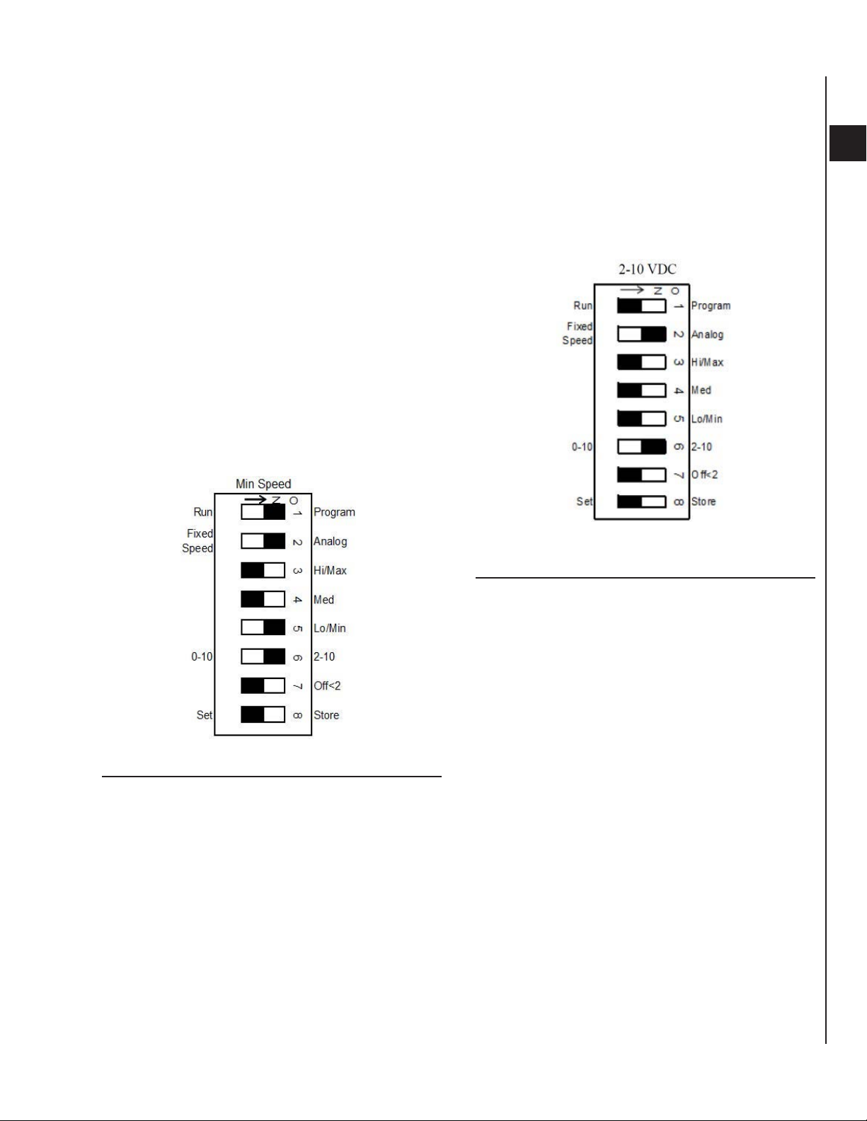
SECTION 2 - START-UPFORM ET115.24-NOM4 (819)
4. Min Speed Adjust: Set conguration switches to
LO/MIN SPEED balancing mode (see Figure 22
on page 31). Switches to ON-ON-OFF-OFFON-ON-OFF-OFF.
• Set switch 1 to ON (Program).
• Set switch 2 to ON (Analog).
• Set switches 3 and 4 to OFF.
• Set switch 5 to ON (Lo/min).
• Set switch 6 to ON (2-10 V).
• Set switches 7 and 8 to OFF.
• Refer to voltmeter connected to TP1 and
TP3. Using an insulated 1/8” flat bladed
screwdriver, adjust speed potentiometer to
desired Min speed airflow.
• STORE: Set switch 8 to Store (ON), wait
one second, then to Set (OFF), to save the
value.
5. Resume Normal 2 – 10 V DC Proportional
Control: Set conguration switches to OFF-ON-
OFF-OFF-OFF-ON-OFF-OFF for normal proportional speed control, as shown in Figure 23 on
page 31.
• Set switch 2 to ON (Analog).
• Set switch 6 to ON (2 – 10).
• Set all other switches to OFF.
2
FIGURE 22 - MIN SPEED ADJUST
FIGURE 23 - NORMAL 2 – 10 VDC SPEED
CONTROL
ENVIRO-TEC
31
Page 32

FORM ET115.24-NOM4 (819)SECTION 2 - START-UP
EC MOTOR TROUBLESHOOTING
GUIDELINES
Ensure motors and blowers are clean as part of normal
maintenance. No further maintenance is required for
these motors.
TABLE 2 - EC MOTOR TROUBLESHOOTING GUIDELINES
PROBLEM POSSIBLE CAUSE CORRECTIVE ACTION
No or loose enable jumper (constant
RPM motor only)
No power to motor. Possible blown
fuse or open circuit breaker
PWM conguration switch in program
mode
PWM board faulted
No control signal (constant RPM)
Motor fails to start
Improper wiring connections
EC motor wiring harness improperly
seated
EC motor wiring harness(es) open or
intermittent
Blower jammed
No 24 VAC power
Float switch tripped Verify oat switch (if present) is made.
Motor seized
Damaged motor cable Cable is integral to motor, replace motor.
Follow standard lock out tag out (LOTO)
procedures when performing service on
motor or blower.
Verify enable jumper connected properly
to motor driver. Refer to Constant RPM
EC Motor Driver Enable Jumper on page
37.
Verify line voltage at motor driver. Replace
fuse or reset circuit breaker.
Conguration switch 1 must be in Run
mode (Figure 13 on page 26). Refer
also to PWM Board Status LED on page
25.
Refer to PWM Board Status LED on page
25. Verify voltage input, wiring and
connections. Push reset button. Replace
PWM board if fault returns.
Constant RPM EC motors will not rotate if
they lose PWM signal while enabled.
Verify PWM signal at motor connector
by connecting a multimeter set for “duty
cycle” between pins 1P1 and 1C (or
between pins 2P1 and 2C). The duty cycle
represents the on-time percentage signal
sent to the motor (this number will vary
between the minimum and maximum duty
cycle set by the factory). See Figure 12 on
page 25 for PWM board connections.
Refer also to PWM Board Status LED on
page 25 to verify board is in normal
operating mode.
Verify wiring. If Fan Coil Relay board
present, verify all jumpers installed. Refer
to Fan Coil Relay Board Troubleshooting
Guide.
Unplug harness and re-install, making
sure plugs are fully seated.
Replace harness(es). See section on
Checking EC Wire Harnesses on page
35.
Clear blockage. Verify blower rotates
freely with motor disconnected.
Refer to Fan Coil Relay Board
Troubleshooting Guide.
Verify motor rotates freely by hand with
blower disconnected. If not, replace
motor.
32
ENVIRO-TEC
Page 33

TABLE 2 - EC MOTOR TROUBLESHOOTING GUIDELINES (CONT'D)
PROBLEM POSSIBLE CAUSE CORRECTIVE ACTION
Fan speed adjustment outside
operating range
Motor surges
Poor performance
Motor starts but stops
Blower Screw loose Tighten Screw onto motor shaft.
ESP (external static pressure) too
high
Lack of required external static
pressure
Speed adjustment outside fan
operating range
Erratic speed command (in
Proportional Control mode)
Damaged or blocked blower
Voltage or ground loss at motor driver
Motor overloaded - blower binding
Motor overloaded
Open ductwork for concealed units Verify ducts sealed properly.
Motor overheated due to lack of
airow
PWM board error or faulted
Motor driver failure
Damaged motor cable Cable is integral to motor, replace motor.
SECTION 2 - START-UPFORM ET115.24-NOM4 (819)
Refer to Fan Calibration curve on unit.
Adjust speed on PWM Controller to
value that will allow motor to start. See
instructions for Adjusting EC Motor Speed
on page 27.
Verify dampers, if present, are not closed.
Verify there are no obstructions in the
discharge ductwork and/or at the plenum
opening. Verify lter is not dirty and does
not obstruct airow.
Add required external static pressure.
Refer to Fan Calibration curve on unit.
Adjust speed on PWM Controller to
value that will allow motor to start. See
instructions for Adjusting EC Motor Speed
on page 27.
Verify 2-10V analog signal at Remote
Control Input terminals.
Verify blower rotates freely. Clear
blockage.
Verify proper voltage and ground at motor
driver power terminals. Refer to Motor
Driver Connections for the EC motor.
Clear blockage. Verify blower rotates
freely with motor disconnected.
Use amp meter to verify motor amps.
Verify motor rotates freely with power
disconnected. If not, replace motor.
Verify dampers, if present, are not closed.
Verify there are no obstructions in the
discharge ductwork and/or at the plenum
opening. Verify lter is not dirty and does
not obstruct airow.
Refer to PWM Board Status LED on page
25. Verify all connections. Push reset
button. Replace board if fault returns.
Replace motor (Constant airow or
constant torque motors.) Replace driver
(Constant RPM motor.)
2
ENVIRO-TEC
33
Page 34

TABLE 2 - EC MOTOR TROUBLESHOOTING GUIDELINES (CONT'D)
PROBLEM POSSIBLE CAUSE CORRECTIVE ACTION
PWM board error or faulted
Improper wiring connections
EC wiring harness damaged or
improperly seated
Motor speed cannot be adjusted
Motor runs in reverse, does not respond
to speed adjustment
Excessive motor noise
Motor runs in G3 PWM Program mode
but not in Run mode
No control signal (constant airow
and constant torque)
ESP (external static pressure) too
high
Motor driver failure
Motor driver failure
Motor mounting bolts loose Tighten motor mounting bolts.
Motor bearing Replace motor.
Motor overloaded
Fan wheel rubbing on fan housing Align wheel in housing.
Loose fan wheel Align and tighten.
Loose pin in Fixed Speed Conn.
harness
FORM ET115.24-NOM4 (819)SECTION 2 - START-UP
Refer to PWM Board Status LED on page
25. Verify all connections. Push reset
button. Replace board if fault returns.
Verify wiring. If Fan Coil Relay board
present, verify all jumpers installed.
Unplug harness and re-install, making
sure plugs are fully seated. See section
on Checking EC Wire Harnesses on page
35. Replace harness if damaged.
Constant airow and constant torque EC
motors will run at idle speed if they lose
PWM signal while enabled.
Verify PWM signal at motor connector
by connecting a multimeter set for “duty
cycle” between pins 1P1 and 1C (or
between pins 2P1 and 2C). The duty cycle
represents the on-time percentage signal
sent to the motor (this number will vary
between the minimum and maximum duty
cycle set by the factory). See Figure 12 on
page 25 for PWM board connections.
Refer also to PWM Board Status LED on
page 25 to verify board is in normal
operating mode.
Verify dampers, if present, are not closed.
Verify there are no obstructions in the
discharge ductwork and/or at the plenum
opening. Verify lter is not dirty and does
not obstruct airow.
Replace motor (constant airow or
constant torque motors)
Replace driver (constant RPM motors)
Replace motor (constant airow or
constant torque motors)
Replace driver (constant RPM motors)
Use amp meter to verify motor amps.
Verify motor rotates freely with power
disconnected. If not, replace motor. Verify
static pressure within limits shown on Fan
Calibration Curve on unit.
Verify that the pins in the Fixed Speed
Conn. harness (see location in Figure 12
on page 25) are inserted fully.
34
ENVIRO-TEC
Page 35

SECTION 2 - START-UPFORM ET115.24-NOM4 (819)
CHECKING EC WIRE HARNESSES
Use ohmmeter to verify that motor ground wire has
continuity from motor case to ground.
To check signal wire harnesses:
• Remove power from the unit. Unplug signal harness at EC driver and from motor connector at
PWM board.
• Use ohmmeter to check continuity for each conductor, then reconnect harnesses to driver and to
PWM board.
To check power wire harness:
• Refer to wiring diagram.
• Remove power from the unit. Unplug power harness at EC driver.
• Verify green wire has continuity to ground.
• Unplug power wires from connections in electrical enclosure. Verify continuity of wires to motor
driver, then reconnect to same terminals.
EC MOTOR AND DRIVER
There are two types of EC motor:
• Constant RPM EC motor, both single and double
shaft.
• Constant Airow or Constant Torque EC motor,
both single and double shaft.
Constant Airflow/Constant Torque EC Motors
LD19307
FIGURE 24 - CONSTANT CFM/CONSTANT
TORQUE EC MOTORS (1/3 HP SHOWN)
2
Before reconnecting power to unit, verify all harnesses
are connected per diagram.
Use light force when inserting meter
probe into plug. Excess force will damage
contacts.
LD19309
FIGURE 25 - CONSTANT CFM/CONSTANT
TORQUE EC MOTOR DRIVER
ENVIRO-TEC
35
Page 36

LD19310
FORM ET115.24-NOM4 (819)SECTION 2 - START-UP
Constant RPM EC Motors
TABLE 3 - SIGNAL CONNECTOR
PIN DESCRIPTION
1 C1 (n/u - com)
2 W/W1 (n/u)
3 C2 (PWM COM)
4 DELAY (n/u)
5 COOL (n/u)
6 Y1 (n/u)
7 ADJUST (n/u)
8 OUT - (PWM FB)
9 O (n/u)
10 PWM
11 HEAT (n/u)
12 R (n/u)
13 EM/W2 (n/u)
14 Y/Y2 (n/u)
15 G (Fan Enable)
16 OUT + (PWM FB)
NOTE:
Connections marked (n/u) are not used.
TABLE 4 - POWER CONNECTOR
PIN DESCRIPTION
1 Jumper pin 1 to pin 2 for 120 VAC Line
2
3 Chassis Ground
4 AC Line (Line 1)
5 AC Line (Line 2, Neutral)
Input only
LD19311
LD19312
FIGURE 26 - CONSTANT RPM EC MOTOR (1/4 HP
SHOWN)
LD19313
FIGURE 27 - CONSTANT RPM EC MOTOR DRIVER
LD19314
TABLE 5 - CON1, POWER INPUT
PIN DESCRIPTION
1 Ground
2 Neutral (or Line 2)
3 Line 1
TABLE 6 - CON502 (IF PRESENT), PROGRAMMING CONNECTOR
PIN DESCRIPTION
1 +15V
2 Ground
3 TX4 TX+
36
TABLE 7 - CON302, PWM SIGNAL INPUT
PIN DESCRIPTION
4 Speed Control Input (H)
3 Speed Control Input (L)
2 Speed Control Input (H)
1 Speed Control Input (L)
ENVIRO-TEC
Page 37

SECTION 2 - START-UPFORM ET115.24-NOM4 (819)
TABLE 8 - CON503 (IF PRESENT), MOTOR ENABLE INPUT
PIN DESCRIPTION
1 No Connection
2 Signal Input
3 Ground
TABLE 9 - CON202, FEEDBACK FROM EC MOTOR
HALL SENSOR
PIN DESCRIPTION
1 +5V
2 Ground
3 Hall "W"
4 Hall "V"
5 Hall "U"
TABLE 10 - CON201, OUTPUT POWER TO MOTOR
PIN DESCRIPTION
1 W1
2 NC
3 V1
4 U1
Constant RPM EC Motor Driver Enable
Jumper
The ETI Constant RPM EC motor driver has a Motor Enable Input. These drivers require a jumper across
the Enable Connector to allow the unit to operate. See
Figure 10 for jumper location across pins 2 and 3 of the
Enable Connector.
LD19308
FIGURE 28 - CONSTANT RPM EC DRIVER EC
MOTOR ENABLE CONNECTOR
2
ENVIRO-TEC
37
Page 38

FORM ET115.24-NOM4 (819)SECTION 2 - START-UP
ECM 3-SPEED CONSTANT TORQUE MOTOR TROUBLESHOOTING GUIDE
TABLE 11 - ECM CONSTANT TORQUE MOTOR SPECIFIC TROUBLESHOOTING GUIDELINES
PROBLEM POSSIBLE CAUSE CORRECTIVE ACTION
Verify the thermostat, if supplied, is operating
HVAC system not calling for operation
Signal voltage at FRCB out of range
Motor voltage not present
Motor Fails to Start
Wiring harness improperly connected
Loose wires in wiring harness
Wiring harness is defective or damaged
Mechanical failure of motor
Motor Surges ESP (external static pressure) too high
Motor mount loose
Excessive Motor Noise
Poor Performance
Motor runs in reverse or not
responding to speed adjustment
* - Fan Coil Relay Board
** - Verify wiring harnesses have no loose wires by gently pulling on each wire.
Fan wheel loose or rubbing on fan
housing
Lack of required ESP
Wrong motor program Contact factory.
Motor failure
properly and/or the applicable thermostat is
connected to your unit.
Verify FCRB* jumper is connected from
‘24VAC’ – ‘R’ terminal to ‘MTR PWR’ terminal.
Measure signal voltage from FCRB ‘24VAC’
– ‘COM’ terminal to each of ‘TO FAN MTR’
‘HIGH’, ‘MED’, and ‘LOW’ terminals. Verify
voltages range from 12 to 33VAC. If any
voltage is out of range, replace the FCRB.
Verify the motor line voltage (black harness
wire) is connected to the applicable ‘LINE
VOLTAGE IN’ terminal on the FCRB.
Measure voltage from the applicable ‘LINE
VOLTAGE IN’ terminal to the ‘P1’ terminal
on the FCRB. Verify the applicable voltage
is present. If no voltage is present, verify
voltage at the line.
With power removed from the unit, verify
that connectors at motor, panel, and FCRB
seat correctly. If not, reconnect them.
With power removed from the unit, verify
that none of the wiring harnesses have loose
wires.**
With power removed from the unit and
the wiring harnesses disconnected, verify
continuity of harness from FCRB and from
equipment ground to motor connector.
Replace wiring harness if suspect. Refer to
ECM Constant Torque Motor Specications
on page 40
Remove power from the unit. Replace the
motor.
Verify there are no discharge obstructions
and the coil ns are clean. Verify plenum is
unobstructed. Verify the lter is clean and
does not obstruct ow of plenum air. Verify
that the High Static Option plug (red) is
connected if static is high.
With power removed from the unit, tighten
motor mounting bolts.
With power removed from unit, loosen fan
wheel, align wheel in housing, then retighten.
Adjust system to provide required static
pressure. (See fan curve.)
Remove power from the unit. Replace
motor.
38
ENVIRO-TEC
Page 39

SECTION 2 - START-UPFORM ET115.24-NOM4 (819)
Procedure for Checking ECM Constant
Torque Wiring Harnesses
1. Remove power from the unit. Lock and tag out
power source.
2. Verify that equipment is properly grounded.
3. Unplug ECM Motor Power wiring harness, and
use ohmmeter to verify continuity (see Table 12
on page 39 for details.)
4. Verify continuity from green wire (motor ground)
to equipment ground.
5. Unplug ECM Motor Signal wiring harness, and
use ohmmeter to verify continuity (see Table 13
on page 40 for details.)
6. Replace all connections. Ensure good connections
are made.
Only very light force is required when
inserting meter probe into plug. Excess
force will damage contacts.
2
ECM Constant Torque Motor Connections
The ECM Constant Torque motor connector is located
on the side of the motor. It has two rows of terminals,
as shown in Figure 29 on page 39. The Power (4pin) connector plugs into the top row. The Signal (5pin) connector plugs into the bottom row.
FIGURE 29 - MOTOR POWER AND SIGNAL CONNECTORS
TABLE 12 - THE ECM CONSTANT TORQUE MOTOR POWER WIRING HARNESS
WIRE COLOR FUNCTION
Purple Signal Common C 24 VAC - COM
Black Line Voltage L
Green Ground G N/A - Ground
White Neutral N P1 - L2/Neut
ENVIRO-TEC
MOTOR
CONNECTION
FCRB CONNECTION
Line Voltage In - see
equipment
39
Page 40

FORM ET115.24-NOM4 (819)SECTION 2 - START-UP
TABLE 13 - THE STANDARD ECM CONSTANT TORQUE MOTOR SIGNAL WIRING HARNESS (WHITE PLUG)
WIRE COLOR FUNCTION
Yellow
Red
Black
Standard Option Low
Speed
Standard Option
Medium Speed
Standard Option High
Speed
MOTOR
CONNECTION
1
3
4
FCRB CONNECTION
TO FAN MOTOR -
LOW
TO FAN MOTOR -
MED
TO FAN MOTOR -
HIGH
TABLE 14 - THE HIGH STATIC ECM CONSTANT TORQUE MOTOR SIGNAL WIRING HARNESS (RED PLUG)
WIRE COLOR FUNCTION
Orange
Gray
Blue
High Static Option Low
Speed
High Static Option
Medium Speed
High Static Option
High Speed
MOTOR
CONNECTION
2
4
5
FCRB CONNECTION
TO FAN MOTOR -
LOW
TO FAN MOTOR -
MED
TO FAN MOTOR -
HIGH
ECM Constant Torque Motor Specifications
TABLE 15 - ECM CONSTANT TORQUE MOTOR PART NUMBERS
TYPE POWER PART # VOLTAGE
ECM 3 SPD 1/3 HP PM-02-0425 277
ECM 3 SPD 1/3 HP PM-02-0426 115
ECM 3 SPD 1/3 HP PM-02-0427 208/230
TABLE 16 - MOTOR SIGNAL TAP SPECIFICATIONS
Min ‘On’ voltage greater than 12VAC or 15VDC
Maximum voltage 33VAC or 23VDC
Min ‘Off’ voltage less than 5.5VAC or 8VDC
Minimum frequency 47 Hz
Nominal frequency 50 or 60 Hz
Maximum frequency 126 Hz
Min current draw 2 m
Nominal current draw 6 mA
Maximum current draw 12 mA
TABLE 17 - GENERAL ECM CONSTANT TORQUE MOTOR SPECIFICATIONS
MAX RATINGS @ NOM V, 1050 RPM
HP
MOTOR+CONTROL
WEIGHT (LBS)
END TO END
LENGTH
TORQUE
(OZ-FT)
WATTS IN
(45C)
WATTS IN
(55C)
40
1/3 9.2 5.275” 27 350 350
ENVIRO-TEC
Page 41

SECTION 2 - START-UPFORM ET115.24-NOM4 (819)
THIS PAGE INTENTIONALLY LEFT BLANK
ENVIRO-TEC
41
Page 42

SECTION 3 - NORMAL OPERATION & PERIODIC MAINTENANCE
SHIELD
BLOWER
OPTIONAL
TYP
(4) PLCS
TYP
(2) PLCS
GENERAL
Each unit on a job will have its own unique operating
environment and conditions that may dictate maintenance schedule for that unit that is different form other
equipment on the job. A formal schedule of regular
maintenance and an individual unit log should be established and maintained. This will help to achieve the
maximum performance and service life of each unit on
the job.
Information regarding safety precautions contained in
the preface at the beginning of this manual should be
followed during any service and maintenance operations.
For more detailed information concerning service operations, consult your Sales Representative or the Factory.
MOTOR/BLOWER ASSEMBLY
The type of fan operation is determined by the control
components and their method of wiring, and may vary
from unit to unit. Refer to the wiring diagram for each
unit for that unit’s individual operating characteristics.
All motors have internal automatic reset thermal overloads.
Should the assembly require more extensive service,
the motor/blower assembly may be removed from the
unit to facilitate such operations as motor or blower
wheel/housing replacement, etc. The motor/ blower assembly is supplied on a slide-out rail system (see Fig-
ure 30 on page 42). To remove, loosen the two lock
nuts at the rack front and slide the blower assembly out.
Disconnect the motor electrical plug to fully remove
the assembly from the unit. To reinstall the blower, repeat the removal sequence in reverse order. The rear of
the blower must catch on the support bracket supplied.
Dirt and dust should not be allowed to accumulate on
the blower wheel or housing. This can result in an unbalanced blower wheel condition that can damage a
blower wheel or motor. The wheel and housing may
be cleaned periodically using a vacuum cleaner and a
brush taking care not to dislodge the factory balancing
weights on the blower wheel blades.
FORM ET115.24-NOM4 (819)SECTION 3 - NORMAL OPERATION & PERIODIC MAINTENANCE
LD13879
FIGURE 30 - MOTOR/BLOWER ASSEMBL Y
COIL
Coils may be cleaned by brushing the entering air
face between fins with a soft brush. Brushing should
be followed by cleaning with a vacuum cleaner. If a
compressed air source is available, the coil may also
be cleaned by blowing air through the coil fins from
the leaving air face. Vacuuming should again follow
this procedure. Units provided with the proper type of
air filters, replaced regularly, will still require periodic
coil cleaning.
ELECTRIC RESISTANCE HEATER ASSEMBLY
Electric resistance heaters typically require no normal
periodic maintenance when unit air filters are changed
properly . The two most important operating conditions
for an electric heater are proper airflow and proper supply voltage. High supply voltage and/or poorly distributed or insufficient airflow over the element will result
in element overheating. This condition may result in the
heater cycling on the high limit thermal cutout. Open
coil strip heaters have an automatic reset switch with
a back-up high limit thermal switch. Automatic reset
switches are as the name implies; they reset automatically after the heater has cooled sufficiently . High limit
thermal switches must be replaced once the circuit has
been broken. The high limit thermal cutout device is a
safety device only and is not intended for continuous
operation. With proper unit application and operation,
the high limit thermal cutout will not deactivate the
heater. This device only operates when some problem
exists and ANY condition that causes high limit cutout
42
ENVIRO-TEC
Page 43

MUST be corrected immediately. High supply voltage
TYP
(6) PLCS
also causes excessive amperage draw and may result in
tripping of the circuit breaker or blowing of the fuses
on the incoming power supply.
Window treatments and drapes must not
be positioned in a manner which obstructs
the air ow through the return air or discharge grilles.
After proper air flow and supply power are assured,
regular filter maintenance is important to provide clean
air over the heater. Dirt that is allowed to deposit on the
heating element will cause hot spots and eventual element burn-through. These hot spots will normally not
be enough to trip the thermal high limit and may not
be evident until actual heater element failure. Heaters
may be serviced through the unit’s electrical section
(see Figure 31 on page 43). To remove heater, disconnect unit power, remove heater connecting wiring
and the element mounting screws.
SECTION 3 - NORMAL OPERATION & PERIODIC MAINTENANCEFORM ET115.24-NOM4 (819)
3
ELECTRICAL WIRING & CONTROLS
The electrical operation of each unit is determined by
the components and wiring of the unit and may vary
from unit to unit. Consult the wiring diagram for the
actual type and number of controls provided on each
unit.
The integrity of all electrical connections should be
verified at least twice during the first year of operation.
Afterwards, all controls should be inspected regularly
for proper operation. Some components may experience erratic operation or failure due to age. Wall thermostats may also become clogged with dust and lint
and should be periodically inspected and cleaned to
provide reliable operation.
When replacing any components such as fuses,
contactors, or relays, use only the exact type, size, and
voltage component as furnished from the factory. Any
deviation without factory authorization could result in
personnel injury or damage to the unit and will void all
factory warranties. All repair work should be done in
such a manner as to maintain the equipment in compliance with governing codes and ordinances or testing
agency listings. More specific information regarding
the use and operating characteristics of the standard
controls offered by this manufacturer is contained in
other manuals.
LD13878
FIGURE 31 - ELECTRIC HEAT
VALVES & PIPING
With the exception of strainers, no formal maintenance
is required on the valve package components most
commonly used with fan coil units. During normal periodic maintenance, the valve packages may be visually inspected for possible leaks.
Valve packages with strainers should have the strainers
cleaned after startup. The strainers may require cleaning several times immediately after startup until the
system is thoroughly cleaned and stabilized. After that,
a schedule should be determined for regular inspection
of the strainers.
In the event that a valve or component should need replacement, the same precautions taken during the initial installation to protect the components from excessive heat should observed during replacement.
ENVIRO-TEC
43
Page 44

FILTERS, THROWAWAY
The type of throwaway filter most commonly used on
fan coil units should be replaced on a regular basis.
The time interval between each replacement should
be established based on regular inspection of the filter
and should be recorded in the log for each unit. Refer
to the product catalog for the recommended filter size
for each product type and size. If the replacement filters are not purchased from the factory, the filters used
should be the same type and size as that furnished from
or recommended by the factory . Consult the factory for
applications using filter types other than the factory
standard or optional product. Dirty filters are the cause
of the most common system performance complaints.
It is essential that filters be serviced on a regular basis.
DRAIN
The drain should be checked before initial start-up and
at the beginning of each cooling season to assure that
the drain trap and line are clear. If it is clogged, steps
should be taken to clear the debris so that condensate
will flow easily.
Periodic checks of the drain should be made during
the cooling season to maintain a free flowing condensate. Should the growth of algae and/or bacteria be a
concern, consult an air conditioning and refrigeration
supply organization familiar with local conditions for
chemicals available to control these agents. The drain
trap is a flexible rubber hose. It is secured to the drain
pan and riser with clamps and is easily removable for
service.
OPTIONAL REMOVABLE DRAIN PAN
FORM ET115.24-NOM4 (819)SECTION 3 - NORMAL OPERATION & PERIODIC MAINTENANCE
LD13880
FIGURE 32 - DRAIN PAN REMOVAL
REPLACEMENT PARTS
Factory replacement parts should be used wherever
possible to maintain the unit performance and operating characteristics and the testing agency listings. Replacement parts may be purchased through the local
Sales Representative.
Contact the local Sales Representative or the factory
before attempting any unit modifications. Any modifications not authorized by the factory could result in
personnel injury and damage to the unit and could void
all factory warranties.
When ordering parts, the following information must
be supplied to ensure proper part identification:
1. Complete unit model number.
2. Unit hand connection (right or left hand) while
facing into the air stream.
An optional removable drain pan is available for easy
service and cleaning (see Figure 32 on page 44). To
remove the pan, disconnect the drain p-trap by loosening the hose clamp under the pan. Remove the retainer
plate at the front of the pan and slide the pan out of
its track. Clean or service pan as appropriate. Reinstall pan in reverse sequence. Retainer plate must be
installed for proper operation.
44
3. Complete part description including any numbers.
On warranty replacements, in addition to the information previously listed, the Factory Order Number
(CO#) that appears on the unit nameplate, is required.
Contact the factory for authorization to return any parts
such as defective parts replaced in warranty. All shipments returned to the factory MUST be marked with
a Return Authorization Number, which is provided by
the factory.
All equipment and components sold through the Parts
Department are warranted under the same conditions
as the standard manufacturers’ warranty with the exception that the warranty period is 12 months unless
the component is furnished as warranty replacement.
Parts furnished as warranty replacements are warranted
for the remaining term of the original unit warranties.
ENVIRO-TEC
Page 45

SECTION 3 - NORMAL OPERATION & PERIODIC MAINTENANCEFORM ET115.24-NOM4 (819)
THIS PAGE INTENTIONALLY LEFT BLANK
ENVIRO-TEC
45
Page 46

FORM ET115.24-NOM4 (819)SECTION 4 - INSPECTION, INSTALLATION & START-UP CHECKLIST
SECTION 4 - INSPECTION, INSTALLATION & START-UP CHECKLIST
RECEIVING & INSPECTION DATE: BY:
Unit Received Undamaged
Unit Received Complete As Ordered
Unit Arrangement Correct
Unit Structural Support Complete & Correct
HANDLING & INSTALLATION
Unit Mounted Level & Square
Proper Access Provided For Unit & Accessories
Proper Electrical Service Provided
Proper Overcurrent Protection Provided
Proper Service Switch/Disconnect Provided
Proper Chilled Water Line Size To Unit
Proper Hot Water Line To Unit
All Services To Unit In Code Compliance
All Shipping Screws & Braces Removed
__________ _________
__________ _________
__________ __________
__________ _________
__________ _________
__________ _________
__________ _________
__________ _________
__________ _________
__________ _________
__________ _________
__________ _________
__________ _________
COOLING/HEATING CONNECTIONS
Protect Valve Package Components From Heat
Mount Valve Packages
Connect Field Piping To Unit
Pressure Test All Piping For Leaks
Install Drain Line & Traps As Required
Insulate All Piping As Required
DUCTWORK CONNECTIONS
Install Ductwork, Fittings & Grilles As Required
Proper Supply & Return Grille Type & Size Used
Control Outside Air For Freeze Protection
Insulate All Ductwork As Required
ELECTRICAL CONNECTIONS
Refer To Unit Wiring Diagram
Connect Incoming Power Service or Services
Electrical Service of Correct Voltage and Ampacityto
Support Unit Operating Loads
All Field Wiring Installed With Code Compliance
Check All Wiring For Secure Connections
__________ _________
__________ _________
__________ _________
__________ _________
__________ _________
__________ _________
__________ _________
__________ _________
__________ _________
__________ _________
__________ _________
__________ _________
__________ _________
__________ _________
__________ _________
46
ENVIRO-TEC
Page 47

SECTION 4 - INSPECTION, INSTALLATION & START-UP CHECKLISTFORM ET115.24-NOM4 (819)
UNIT START-UP DATE: BY:
General Visual Unit & System Inspection
Record Electrical Supply Voltage
Record Ambient T emperature
Close All Unit Isolation Valves
Flush Water Systems
Fill Systems With Water/Refrigerant
Vent Water Systems As Required
All Ductwork & Grilles In Place
All Unit Panels & Filters In Place
Start Fans, Etc.
Check For Overload Condition Of All Units
Check All Ductwork & Units For Air Leaks
Balance Air Systems As Required
Record All Final Settings For Future Use
Check Piping & Ductwork For Vibration
Check All Dampers For Proper Operation
Verify Proper Cooling Operation
Verify Proper Heating Operation
Reinstall All Covers & Access Panels
__________ _________
__________ _________
__________ _________
__________ _________
__________ _________
__________ _________
__________ _________
__________ _________
__________ _________
__________ _________
__________ _________
__________ _________
__________ _________
__________ _________
__________ _________
__________ _________
__________ _________
__________ _________
__________ _________
4
SERVICE INTERVALS (record dates service performed):
Filters: ______________________________________________________________________________________________
Drain Pan:___________________________________________________________________________________________
Motor/Blower: _________________________________________________________________________________________
Coil: _______________________________________________________________________________________________
Controls:____________________________________________________________________________________________
General: ____________________________________________________________________________________________
ENVIRO-TEC
47
Page 48

SYMPTOM POSSIBLE CAUSE CORRECTIVE ACTION
NO UNIT OPERATION
UNIT BLOWS MAIN UNIT OR
FAN MOTOR FUSE WHEN
POWER IS APPLIED TO UNIT
FAN DOES NOT RUN WITH
POWER TO UNIT
SECTION 5 - TROUBLESHOOTING
No power to unit. Apply proper power to unit.
Improper power to unit.
Power distribution panel
switch or circuit breaker in
“OFF” position.
Unit toggle or door interlock
disconnect switch in “OFF”
position.
Fan switch or thermostat
system switch in “OFF”
position.
Blown or defective unit main
fuse, if furnished.
Blown or defective fan motor
fuse, if furnished.
Defective toggle, door
interlock, fan, or thermostat
system switch.
Loose or improper wiring
from power distribution and/
or remote mounted control
devices.
Defective or improperly wired
component.
Fan switch in “OFF” position. Turn fan switch to “ON” position.
Thermostat system switch in
“OFF” position.
Remote “start/stop” switch in
“OFF” position.
Loose or improper wiring from
fan switch or thermostat to
unit.
Loose or improper wiring from
remote “start/stop” switch to
unit “start/stop” relay.
Defective fan switch.
Defective “start/stop” relay.
Defective fan motor.
Apply proper power to unit and check for damaged
components and/or blown fuses, if furnished.
Turn power distribution panel switch or circuit breaker to
“ON” position.
Turn unit toggle or door interlock disconnect switch to
“ON” position.
Turn fan switch or thermostat system switch to “ON”
position.
Check for possible defective component or improper
wiring, and replace fuse.
Check for possible defective component or improper
wiring, and replace fuse.
Momentarily jumper suspected component to simulate
closed contacts and achieve unit operation. Replace
defective device with known good part.
Verify all wiring connections and terminations, and verify
proper wiring of all incoming power devices and remote
mounted controls.
Using a battery powered continuity tester, check for
shorted or grounded components starting at incoming
power. Note position of all controls during various
component checks. Caution: some voltages have
isolated common which may not show a short to chassis
ground. Be sure to isolate each control to eliminate
faulty reading through a parallel wired component.
Turn thermostat system switch to “ON” position.
Turn remote “start/stop” switch to “ON” position.
Verify all wiring connections and terminations, and verify
proper wiring of all control devices.
Verify all wiring connections and terminations, and verify
proper wiring of remote “start/stop” switch.
Momentarily jumper fan switch to each fan speed wire to
simulate proper fan switch operation. Replace defective
fan switch.
Momentarily jumper “start/stop” relay to simulate proper
relay operation. Replace defective “start/stop” relay.
Verify proper fan switch operation and replace defective
fan motor.
FORM ET115.24-NOM4 (819)SECTION 5 - TROUBLESHOOTING
48
ENVIRO-TEC
Page 49

SYMPTOM POSSIBLE CAUSE CORRECTIVE ACTION
FAN MOTOR HUMS AND/OR
GETS HOT, BUT RUNS AT
REDUCED SPEED OR
NOT A T ALL
FAN RUNS BUT VIBRATES
FAN RUNS BUT BLOWER
WHEEL RUBS HOUSING
FAN RUNS BUT AIR
DELIVERY IS LOW
FAN RUNS BUT NO COOLING/
HEATING. (HYDRONIC UNITS)
SECTION 5 - TROUBLESHOOTINGFORM ET115.24-NOM4 (819)
Improper power applied to
unit.
Defective motor capacitor. Replace with known good capacitor.
Defective fan motor. Replace defective motor.
Blower wheel jammed in
housing.
Foreign object in blower
wheel.
Blower wheel dirty.
Blower wheel bent. Replace blower wheel.
Blower wheel out of balance. Replace blower wheel.
Foreign object in blower
wheel.
Loose motor mount screws.
Broken motor mount frame or
mounting screws.
Bent blower wheel. Replace blower wheel.
Blower wheel not positioned
properly on motor shaft.
Incorrect fan speed has been
selected.
Dirty air lter. Replace air lter.
Dirty coil. Clean coil.
Obstruction in ductwork.
Actual E.S.P. higher than
design.
No chilled/hot water ow in
system.
Unit isolation valves closed. Open unit isolation valves.
Debris in water piping
blocking ow.
Plugged strainer on units so
equipped.
Riser or main ushing loop
open.
Loose or improper wiring from
thermostat to control valve.
Defective thermostat.
Defective control valve
actuator.
Improper aquastat operation
on units so equipped.
Apply proper power to unit.
Reposition blower wheel for proper alignment in housing,
or replace if damaged.
Remove foreign object and replace blower wheel if
damaged.
Remove and clean blower wheel taking care not to
remove or reposition balance weights.
Remove foreign object and replace blower wheel if
damaged.
Verify proper motor and blower wheel position and
tighten motor mount screws. Do not crush mounting
grommets.
Replace motor or mounting screws.
Check for damage to blower wheel. Reposition blower
wheel on motor shaft or replace as required.
Reselect proper fan speed as required.
Check for improperly positioned balancing or re
dampers. Check for fallen duct liner. Repair as required.
Check installation for proper supply and/or return grilles,
and compliance with plans and specications.
Establish chilled/hot water ow in system as required.
Locate and clear debris from water piping as required.
Clean or remove strainer screen as required.
Close ushing loop valve as required.
Verify all wiring connections and terminations, and verify
proper wiring of thermostat.
Momentarily jumper thermostat contacts to simulate
proper operation. Replace thermostat as required.
Manually place control valve in “open” position using
lever on actuator housing. Replace actuator as required.
Verify proper aquastat position and operation. Replace
as required.
5
ENVIRO-TEC
49
Page 50

SYMPTOM POSSIBLE CAUSE CORRECTIVE ACTION
FAN RUNS BUT NO HEATING.
(ELECTRIC HEAT UNITS)
No power to electric heat
circuit on units with dual point
power.
Loose or improper wiring from
thermostat to electric heat
contactor.
Loose or improper wiring of
electric heat element.
Defective electric heat
contactor.
Tripped or defective primary
high limit switch.
Tripped secondary high limit
switch.
Defective thermostat.
Defective electric heat
element.
Improper aquastat or change
over relay operation on units
so equipped. (Note: electric
heat will not operate when
hot water is present at the
unit.)
FORM ET115.24-NOM4 (819)SECTION 5 - TROUBLESHOOTING
Establish power to electric heat circuit.
Verify all wiring connections and terminations, and verify
proper wiring of thermostat.
Verify all wiring connections and terminations, and verify
proper wiring of electric heat element.
With electric heat contactor energized, verify proper
voltage on contactor load terminals. Replace as
required.
Turn thermostat to lowest set point and allow fan to run
10-15 minutes for limit switch to cool and reset. Then
turn thermostat to highest set point and check for proper
heating operation. If high limit trips again, check for the
following conditions: improper voltage to heater element;
obstructed fan or unit outlet reducing air ow over heater
element; dirty or defective heater element causing hot
spot. If heater does not operate after sufcient time
for limit switch to cool, disconnect power and check
continuity across primary high limit switch. Replace if
defective.
Secondary high limit switches are designed to trip only
during extreme failure conditions. Contact factory before
attempting any corrective action.
Momentarily jumper thermostat contacts to simulate
proper operation. Replace thermostat as required.
Disconnect power and check continuity through heat
element. Replace as required.
Verify proper aquastat position on piping, and verify
proper aquastat and change over relay operation.
Replace as required.
TROUBLESHOOTING REFERENCE
Component Description Guide Name Option Description
Fan Relay Board (FCRB) –
Fan Coil Relay Board (FCRB)
Installation, Operation and
Maintenance
Fan Relay Board II (FRBii)
Fan Relay Board II (FRBii)
– Installation, Operation and
Maintenance
G3 PWM Board Fan Coil EC Motor IOM
NOTE:
All documents downloadable at www.enviro-tec.com.
50
1st generation relay board, 24V Control
Packages, units shipped before 3/31/2017
2nd generation relay board, 24V Control
Packages
ECM controller on variable speed ECM
units
ENVIRO-TEC
Page 51

FORM ET115.24-NOM4 (819)
SECTION 6 - DIMENSIONAL DATA
The drawings in this section are for reference only and should not be used for construction purposes. Reference
submittal documents for most current version.
6
FIGURE 33 - MODEL VHM, VERTICAL CONCEALED MASTER HIGH RISE, FCU, 88" CABINET
ENVIRO-TEC
74-80080
51
Page 52

FORM ET115.24-NOM4 (819)SECTION 6 - DIMENSIONAL DATA
FIGURE 34 - MODEL VHS, VERTICAL CONCEALED SLAVE HIGH RISE, FCU, 88" CABINET
52
74-80081
ENVIRO-TEC
Page 53

SECTION 6 - DIMENSIONAL DATAFORM ET115.24-NOM4 (819)
6
74-80083
FIGURE 35 - MODEL VHA/VHB, VERTICAL HI-RISE TANDEM FIRE RATED AND NON-FIRE RATED, FCU
COMBINATIONS, 88" CABINETS
ENVIRO-TEC
53
Page 54

FORM ET115.24-NOM4 (819)SECTION 6 - DIMENSIONAL DATA
74-80083
54
ENVIRO-TEC
Page 55

SECTION 6 - DIMENSIONAL DATAFORM ET115.24-NOM4 (819)
6
FIGURE 36 - MODEL VH, VERTICAL CONCEALED HIGH RISE FAN COIL UNIT WITH 79" CABINET
ENVIRO-TEC
VH-031
55
Page 56

FORM ET115.24-NOM4 (819)SECTION 6 - DIMENSIONAL DATA
VH-032
FIGURE 37 - MODEL VHM, VERTICAL CONCEALED MASTER HIGH RISE FAN COIL UNIT WITH 79" CABINET
56
ENVIRO-TEC
Page 57

SECTION 6 - DIMENSIONAL DATAFORM ET115.24-NOM4 (819)
6
VH-033
FIGURE 38 - MODEL VHS, VERTICAL CONCEALED SLAVE HIGH RISE FAN COIL UNIT WITH 79" CABINET
ENVIRO-TEC
57
Page 58

FORM ET115.24-NOM4 (819)SECTION 6 - DIMENSIONAL DATA
See page 67 for dimensions.
Refer to page 61, page 62, page 63 & page 64 for vertical Hi-rise
Tandem Master & Tandem Slave configurations.
on page 75.
FIGURE 39 - MODEL VHA/VHB, VERTICAL HI-RISE FIRE RATED AND NON-FIRE RATED FCU
COMBINATIONS, 79" CABINETS
58
VH-006-1
ENVIRO-TEC
Page 59

DIMENSIONS - In. (mm) VHA SUPPLY AIR VHB SUPPLY AIR
VHA
(MASTER)
03 or 04 03 or 04
03 or 04 06 or 08
03 or 04 10 or 12
VHB
(SLAVE)
A B C D
18
(457)
20
(508)
24
(610)
42-1/4
(1073)
46-1/4
(1175)
54-1/4
(1378)
16-1/2
(419)
18-1/2
(470)
22-1/2
(572)
SECTION 6 - DIMENSIONAL DATAFORM ET115.24-NOM4 (819)
SINGLE DOUBLE TOP SINGLE DOUBLE TOP
E E F G E E F G
16
(406)
18
(457)
22
(559)
8 (203) 8 (203)
8 (203) 8 (203)
8 (203) 8 (203)
6
(152)8 (203)
6
12
(152)
(305)
8
12
(203)
(305)
8 (203) 8 (203)
8 (203) 8 (203)
8 (203)
6
(152)8 (203)
6
12
(152)
(305)
8
12
(203)
(305)
06 or 08 03 or 04
06 or 08 06 or 08
06 or 08 10 or 12
10 or 12 03 or 04
10 or 12 06 or 08
10 or 12 10 or 12
See page 58 for notes.
20
(508)
24
(610)
24
(610)
46-1/4
(1175)
54-1/4
(1378)
54-1/4
(1378)
18-1/2
(470)
22-1/2
(572)
22-1/2
(572)
18
(457)
22
(559)
22
(559)
8 (203) 8 (203)
8 (203) 8 (203)
8 (203)
6
(152)
8
(203)
8
(203)
12
(305)
12
(305)
12
(305)
8 (203) 8 (203)
8 (203)
8 (203)
6
(152)
8
(203)
8
(203)
12
(305)
12
(305)
12
(305)
6
ENVIRO-TEC
59
Page 60

FORM ET115.24-NOM4 (819)SECTION 6 - DIMENSIONAL DATA
VHC/VHS/VHM
&
VHA/VHB
VHA/VHB
FIGURE 40 - MODEL VH, VERTICAL HIGH RISE COIL UNIT, ALUMINUM DISCHARGE GRILLE
60
74-80020
ENVIRO-TEC
Page 61

SECTION 6 - DIMENSIONAL DATAFORM ET115.24-NOM4 (819)
MODEL VHC UNITS SHOWN ABOVE WITH OPTIONAL RISER CHASE.
RISER CHASE NOT AVAILABLE ON VHM UNITS. VHA UNITS MUST
BE MATED TO VHB UNITS.
6
SEE PAGE 63 FOR DETAILS.
VH-010
FIGURE 41 - MODEL VHC/VHM/VHA VERTICAL HIGH RISE FAN COIL UNIT ARRANGEMENT DESIGNATIONS
ENVIRO-TEC
61
Page 62

FORM ET115.24-NOM4 (819)SECTION 6 - DIMENSIONAL DATA
VHC AND VHS
VHB
VHA
SEE PAGE 63 FOR DETAILS.
FIGURE 42 - MODEL VHC W/O RISERS & VHS/VHB VERTICAL HIGH RISE FAN COIL UNITS, UNIT
ARRANGEMENT DESIGNATIONS
62
VH-011
ENVIRO-TEC
Page 63

SECTION 6 - DIMENSIONAL DATAFORM ET115.24-NOM4 (819)
VHC
VH
6
FIGURE 43 - MODEL VH VERTICAL HIGH RISE COIL UNIT OUTSIDE INLET DIMENSIONS
ENVIRO-TEC
VH-018
63
Page 64

FORM ET115.24-NOM4 (819)SECTION 6 - DIMENSIONAL DATA
TANDEM MASTER & TANDEM SLAVE INSTALLATION
INSTRUCTIONS ON PAGES
TANDEM MASTER
& TANDEM SLAVE
FIRE RATED
TANDEM MASTER
& TANDEM SLAVE
NON-FIRE RATED
page 75 - page 77.
FIGURE 44 - MODEL VHM/VHA/VHC TANDEM MASTER & TANDEM SLAVE UNIT CONFIGURATION FAN COIL UNIT
VH-043
64
ENVIRO-TEC
Page 65

SECTION 6 - DIMENSIONAL DATAFORM ET115.24-NOM4 (819)
6
VH-106
FIGURE 45 - ASSEMBLY INSTRUCTIONS RETURN PANEL WITH LATCHES, QUICK OPENING OR TAMPER
PROOF, MODEL VHC/VHM/VHS HIGH RISE FCU
ENVIRO-TEC
65
Page 66

VHS
VHS
VH
VH
VHS
FORM ET115.24-NOM4 (819)SECTION 6 - DIMENSIONAL DATA
FIGURE 46 - PREPARATION INSTRUCTIONS FOR MODEL VHC/VHM VERTICAL HIGH RISE FCU "SHIP
LOOSE" RISER ASSEMBLIES
66
ENVIRO-TEC
Page 67

SECTION 6 - DIMENSIONAL DATAFORM ET115.24-NOM4 (819)
6
FIGURE 47 - FULL LOUVERED ALUMINUM RETURN AIR/WALL PANEL MODEL VH VERTICAL HIGH RISE
FAN COIL UNIT
ENVIRO-TEC
VH-013
67
Page 68

FORM ET115.24-NOM4 (819)SECTION 6 - DIMENSIONAL DATA
74-80084
FIGURE 48 - MODEL VH VERTICAL HIGH RISE FAN COIL UNIT STANDARD SURFACE MOUNT WALL PANEL
68
ENVIRO-TEC
Page 69

SECTION 6 - DIMENSIONAL DATAFORM ET115.24-NOM4 (819)
assembly instructions on
in Tandem Master & Tandem Slave pairs.
VH-014
6
page 65 for details.
FIGURE 49 - RECESSED WALL PANEL MODEL VH VERTICAL HIGH RISE FAN COIL UNIT
ENVIRO-TEC
69
Page 70

FORM ET115.24-NOM4 (819)SECTION 6 - DIMENSIONAL DATA
assembly instructions on page for details.
in Tandem Master & Tandem Slave pairs.
VH-047
FIGURE 50 - MODEL VH VERTICAL HIGH RISE FAN COIL UNIT STANDARD RETURN WALL PANEL WITH
ADA THERMOSTAT
70
ENVIRO-TEC
Page 71

SECTION 6 - DIMENSIONAL DATAFORM ET115.24-NOM4 (819)
TABLE 18 - DISCHARGE REGISTER PERFORMANCE DATA, VH STANDARD FCU 88" CABINET, SINGLE
AND DOUBLE SUPPLY
SINGLE SUPPLY
UNIT
SIZE
CFM
(SEE NOTE 5)
W (IN.) H (IN.)
Pv
(in W.G.)
03 375 16 8 0.013 0.0370 0.0240 <20 16-36 9.5
04 450 16 8 0.018 0.0524 0.0344 <20 19-38 10
06 616 18 12 0.017 0.0523 0.0353 <20 18-45 13
08 860 18 12 0.024 0.0698 0.0458 26 26-52 16
10 966 22 14 0.017 0.0524 0.0354 21 27-62 21
12 1350 22 14 0.024 0.0697 0.0457 26 33-69 23
DOUBLE SUPPLY
UNIT
SIZE
CFM
(SEE NOTE 5)
W (IN.) H (IN.)
Pv
(in W.G.)
03 375 16 8 0.006 0.0170 0.0110 <20 11-24 10
04 450 16 8 0.008 0.0230 0.0150 <20 11-27 10.5
06 616 18 12 0.003 0.0072 0.0042 <20 10-35 11.5
08 860 18 12 0.006 0.0170 0.0110 <20 12-37 12
10 966 22 14 0.006 0.0170 0.0110 <20 13-42 12
12 1350 22 14 0.008 0.0230 0.0150 <20 14-45 14
REGISTER DATA
Pt
(in W.G.)
(IN W.G.)
REGISTER DATA
Pt
(in W.G.)
(IN W.G.)
Ps
Ps
NC
NC
THROW
(FT)
THROW
(FT)
DROP
(FT)
DROP
(FT)
6
NOTES:
1. NC data is at 0° deflection. For 22.5° deflection, add 1 NC. For 45° deflection, add 7 NC.
2. Throws are for velocities of 50 and 150 FPM at 0° deection.
3. For 22. 5° and 45° deection, multiply by 0.67.
4. Drops are at 0° deection. For 22.5° deection, multiply by 0.85. For 45° deection, multiply by 0.66.
5. Register Data is based on zero static and CRM show at high speed motor operation.
6. Data above does not reect optional opposed blade damper information.
ENVIRO-TEC
71
Page 72

FORM ET115.24-NOM4 (819)SECTION 6 - DIMENSIONAL DATA
TABLE 19 - DISCHARGE REGISTER PERFORMANCE DATA, VH STANDARD FCU 79" CABINET, SINGLE
AND DOUBLE SUPPLY
SINGLE SUPPLY
UNIT
SIZE
CFM
(SEE NOTE 5)
W (IN.) H (IN.)
Pv
(in W.G.)
03 375 16 8 0.013 0.0370 0.0240 <20 13-32 10
04 450 16 8 0.018 0.0524 0.0344 23 20-39 10.5
06 616 18 8 0.026 0.0765 0.0505 32 20-39 10.5
08 860 18 8 0.054 0.1624 0.1084 39 32-54 17
DOUBLE SUPPLY
UNIT
SIZE
03 375 16 8
CFM
(SEE NOTE 5)
W (IN.) H (IN.)
Pv
(in W.G.)
0.003 0.0072 0.0042 <20 8-25 9
04 450 16 8 0.005 0.0160 0.0110 <20 9-25 10
06 616 18 8 0.007 0.0180 0.0110 <20 13-30 10
08 860 18 8
0.015 0.0380 0.0230 21 18-39 11
10 966 22 8 0.015 0.0380 0.0230 <20 17-42 12.5
12 1350 22 8 0.019 0.0560 0.0370 21 21-45 14
REGISTER DATA
Pt
(in W.G.)
(IN W.G.)
REGISTER DATA
Pt
(in W.G.)
(IN W.G.)
Ps
Ps
NC
NC
THROW
(FT)
THROW
(FT)
DROP
(FT)
DROP
(FT)
NOTES:
1. NC data is at 0° deflection. For 22.5° deflection, add 1 NC. For 45° deflection, add 7 NC.
2. Throws are for velocities of 50 and 150 FPM at 0° deection.
3. For 22. 5° and 45° deection, multiply by 0.67.
4. Drops are at 0° deection. For 22.5° deection, multiply by 0.85. For 45° deection, multiply by 0.66.
5. Register Data is based on zero static and CRM show at high speed motor operation.
6. Data above does not reect optional opposed blade damper information.
72
ENVIRO-TEC
Page 73

SECTION 6 - DIMENSIONAL DATAFORM ET115.24-NOM4 (819)
6
FIGURE 51 - SUGGESTED RISER FLOOR OPENINGS VHC & VHM
ENVIRO-TEC
VH-109
73
Page 74
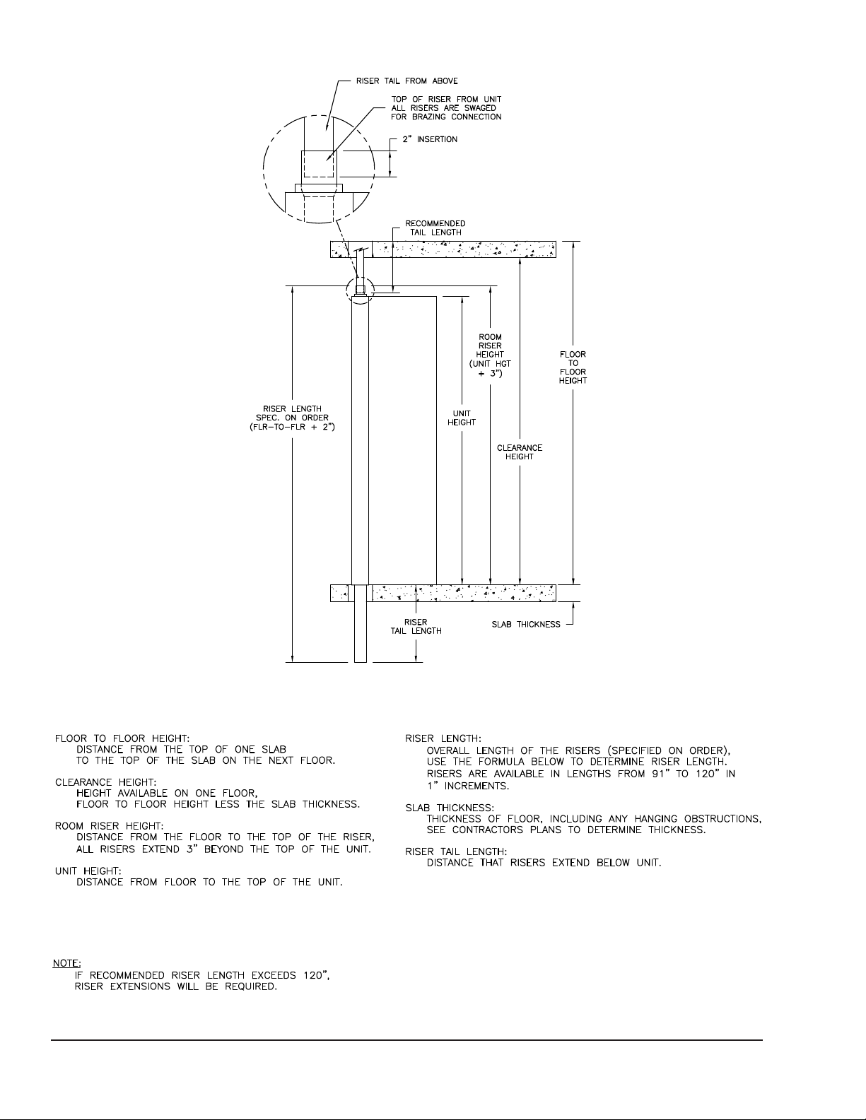
FORM ET115.24-NOM4 (819)SECTION 6 - DIMENSIONAL DATA
FIGURE 52 - RISER TERMINOLOGY, MODEL VHC, VHM, VHA UNITS
74
VH-110
ENVIRO-TEC
Page 75

SECTION 6 - DIMENSIONAL DATAFORM ET115.24-NOM4 (819)
VERTICAL HI-RISE TANDEM UNITS
VHA/VHB INSTALLATION INSTRUCTIONS
Receipt & Initial Installation
General
This publication details the installation requirements
for the Enviro-Pac dual unit configuration of the Vertical High Rise, VH, unit assembly. Use of this document for systems or products not manufactured or supplied by ENVIRO-TEC shall not be applicable.
All products covered by this manual have been tested in accordance with UL1479 (2012) - Fire Tests
Of Through Penetration Fire Stop Assemblies. Specific information about the ENVIRO-PAC VHA/VHB
UL1479 (2012) listing may be viewed on the Warnock
Hersey Listed Product Directory at https://whdirectory .
intertek.com. Reference WH file number JCI/PF60-01.
Specific ETL listed model numbers may be found in
the current ETL Listed Mark Directory at http://www.
intertek.com/directories/.
For other VH product installation and operational instructions, refer to IOM-FCUVH.
The Installation Instructions found within this manual
have been specifically drawn and detailed to meet the
requirements of UL1479 (2012). Some jurisdictions
may have additional installation requirements above
and beyond those detailed in this document; consult
with the authority having jurisdiction for specific additional requirements. In all cases, the instructions detailed in this document must be followed to maintain
the UL 1479 (2012) fire rating.
Installation
1. In order to achieve the 1 hour re rating, ENVIRO-PAC unit assembly must be installed into a
minimum 1-hour re rated wall assembly of gypsum and steel stud, gypsum and wood stud, concrete, or masonry construction with a minimum
overall thickness of 4-3/4”. The wall assembly
shall extend into the unit spacer plate. When applicable, attach studs of the wall to the unit spacer
plate with sheet metal screws spaced nominally
12” O.C. When built of gypsum construction, the
following minimum requirements must be met.
a. Studs – Wood or steel studs nominal 3-1/2”
thick, spaced maximum 24” O.C.
b. Gypsum Board – Minimum 5/8“ Type X
Gypsum board with a minimum of one layer.
Gypsum board must be installed on each side
of the wall assembly.
2. Place unit assembly in its desired location. Check
riser number, oor number, room number, and
unit tag number against the tag label on the unit,
making sure that the unit assembly is installed
with the space between the two units centered in
the wall between each room.
3. Anchor unit assembly to oor through unit bot-
tom. Due to oor leveling, some shimming may
be necessary so unit is plumb and square to oor/
ceiling.
4. Install oor stud reception channels up to unit
sides at the connector plate.
5. Install ceiling stud reception channel over the unit
assembly, leaving space for riser penetration.
6. Install the wall studs into the recess in the unit
assembly using #6 x ½ drywall screws spaced as
necessary.
A void placing screws where they may penetrate the risers, coil, piping, or electrical
system.
7. Install balance of the studs into ceiling/oor reception channels at a spacing to meet project
specications and local, state, or national codes.
In no cases should stud spacing be greater than
24” O.C.
8. Install studs from top of unit to ceiling. Locates
studs at each unit corner.
9. Make necessary electrical and plumbing connections to unit.
10. Two installation congurations may be used for
the ENVIRO-PAC units. The following details
standard installation per Figure 53 on page 76.
a. Install minimum 5/8” Type X gypsum board
to all exposed sides of the unit exterior, including top and front. Gypsum panels may
be applied directly to unit casing or may be
furred out for plumbness. Any supply air,
outside air, or thermostat openings shall be
let-in as necessary.
6
ENVIRO-TEC
75
Page 76

b. The gypsum panel installed to the face of the
Gypsum may have cut out to
accomodate supply, return
and thermostat
1
1A
2
Factory Installed
Insulation
1A
Factory Installed
Gypsum
LD19316
A
ttached to pre-existing ceiling or floor assembly
1Bi
unit should be applied directly to the front
of the unit, unless a wall recessed return air
grille is used, in which case this panel will be
furred-out. Any supply air , return air , or ther mostat openings shall be let-in as necessary.
c. Attach gypsum board to unit with sheet met-
al screws spaced 8” O.C. around the perimeter and 12” O.C. in the field, ensuring that
screws are not located where they might penetrate interior working of unit.
d. Gypsum board shall be tightly butted against
the wall assembly on all exposed sides, including top of unit.
11. For alternate installation per Figure 54 on page
76, unit framing must be installed to top of unit.
a. Install minimum 25 GA, nominal 3-1/2”
wide, steel track to the top of the fan coil
unit, at top front and two top sides as shown
in Figure 54 on page 76.
FORM ET115.24-NOM4 (819)SECTION 6 - DIMENSIONAL DATA
FIGURE 53 - STANDARD INSTALLATION
b. Attach steel track using sheet metal screws
spaced 12” O.C.
c. Install identical steel track to the ceiling or
floor assembly using appropriate anchors.
Friction fit minimum 25 GA nominal 3-1/2”
steel studs into the top and bottom track and
secure with pan head screws.
d. Install one stud at each corner of the fan coil
unit.
e. Install gypsum board to the front and side of
the fan coil unit as described in Step 10.
f. Extend the gypsum board to the ceiling or
floor assembly, attaching to steel studs and
track with Type S screws spaced maximum
8” O.C.
12. Risers shown in the standard location. Risers may
be installed on the left or right side of Unit A. Wall
construction should remain the same, regardless
of riser location.
LD19316
FIGURE 54 - ALTERNATE INSTALLATION
76
ENVIRO-TEC
Page 77

B B
1/2" TYP
SPACING AS
NECESSARY
10. INSTALL GYPSUM BOARD TO SIDES
OF UNIT WITH OPTIONAL CUT OUTS FOR
SUPPLY, OUTSIDE AIR, AND THERMOSTAT
11. INSTALL GYPSUM BOARD TO FACE
OF UNIT WITH OPTIONAL CUT OUTS
FOR SUPPLY, RETURN, AND THERMOSTAT
7. INSTALL STUDS FROM TOP OF
UNIT TO CEILING (4 CORNERS)
9. INSTALL GYPSUM BOARD TO WALLS
SHEET 2 OF 2
5. INSTALL WALL STUD INTO
RECESS FORMED BY
CONNECTOR PLATE
SEE DETAIL A ABOVE
MAY VARY
RISER LOCATION
WALL STUDS
=5/8" TYPE-X GYPSUM BOARD, FIELD SUPPLIED
=5/8" TYPE-X GYPSUM BOARD, FACTORY SUPPLIED
3 5/8-25 GA STEEL STUD
24" O.C. TYP
#6 X 1/2" DRYWALL SCREWS
CAUTION-AVOID PLACING SCREW WHERE THEY MAY PENETRATE
THE RISER, COIL, PIPING, OR ELECTRICAL SYSTEM.
CONNECTOR PLATE
PLAN VIEW
UNIT A UNIT B
SECTION "B-B"
UNIT A
DETAIL-A
UNIT B
PX-70-0001
SECTION 6 - DIMENSIONAL DATAFORM ET115.24-NOM4 (819)
6
FIGURE 55 - MOUNTING DETAILS
ENVIRO-TEC
LD13947
77
Page 78

NOTES
FORM ET115.24-NOM4 (819)SECTION 6 - DIMENSIONAL DATA
78
ENVIRO-TEC
Page 79

FORM ET115.24-NOM4 (819)
The following factors can be used to convert from
English to the most common SI Metric values.
TABLE 20 - SI METRIC CONVERSION
MEASUREMENT MULTIPLY ENGLISH UNIT BY FACTOR TO OBTAIN METRIC UNIT
Capacity Tons Refrigerant Effect (ton) 3.516 Kilowatts (kW)
Power Horsepower 0.7457 Kilowatts (kW)
Flow Rate Gallons / Minute (gpm) 0.0631 Liters / Second (l/s)
Feet (ft) 0.3048 Meters (m)
Length
Inches (in) 25.4 Millimeters (mm)
Weight Pounds (lbs) 0.4538 Kilograms (kg)
Velocity Feet / Second (fps) 0.3048 Meters / Second (m/s)
Feet of Water (ft) 2.989 Kilopascals (kPa)
Pressure Drop
Pounds / Square Inch (psi) 6.895 Kilopascals (kPa)
TEMPERATURE
To convert degrees Fahrenheit (°F) to degrees Celsius
(°C), subtract 32° and multiply by 5/9 or 0.5556.
Example: (45.0°F - 32°) x 0.5556 = 27.2°C
To convert a temperature range (i.e., a range of 10°F)
from Fahrenheit to Celsius, multiply by 5/9 or 0.5556.
Example: 10.0°F range x 0.5556 = 5.6 °C range
ENVIRO-TEC
79
Page 80

ENVIRO-TEC is a registered trademark of Johnson Controls in the United States of America and other countries.
Other trademarks used herein may be trademarks or registered trademarks of other companies.
Catalog: ET115.24-NOM4 (819) Supersedes ET115.24-NOM4 (317)
© 2019 Johnson Controls
www.enviro-tec.com
 Loading...