

Page 1

HORIZONTAL, LOW PROFILE FAN COILS
Series D
INSTALLATION, OPERATION & MAINTENANCE
Supersedes ET115.24-NOM11 (417)
Form ET115.24-NOM11 (118)
Page 2

TABLE OF CONTENTS
Safety Symbols . . . . . . . . . . . . . . . . . . . . . . . . . . . . 1
Safety Considerations ....................... 1
FORM ET115.24-NOM11 (118)
Section One - Receipt & Initial Installation
HL Series Features.......................... 2
Preface ................................... 3
Unpacking & Inspection ...................... 3
Handling & Installation ....................... 3
Drain Pan . . . . . . . . . . . . . . . . . . . . . . . . . . . . . . . . . 5
Coils . . . . . . . . . . . . . . . . . . . . . . . . . . . . . . . . . . . . . 5
Cooling/Heating Medium Connections ........... 6
Auxiliary Drain Pans ......................... 7
Ductwork Connections . . . . . . . . . . . . . . . . . . . . . . . 7
Electrical Connections ....................... 7
Electrical Enclosure ......................... 7
Telescoping Bottom Panel .................... 8
Model HLP Horizontal Fan Coil Optional
Telescoping Bottom Panel Assembly,
Typical Installation Instructions ............. 9
Service & Clearance Requirements ............ 10
Height Restricted Application . . . . . . . . . . . . . . . . . 11
Width Restricted Application..................12
External Space Requirements ................ 13
Section Two - Start-Up
General.................................. 14
Cooling/Heating System.....................14
Air System Balancing ....................... 14
Motor & Fan Data .......................... 15
Water System Balancing .................... 16
Controls Operation ......................... 16
Electric Resistance Heater Assembly........... 18
Electrical Wiring & Controls .................. 18
Valves & Piping............................ 18
Filters, Throwaway ......................... 19
Drain....................................20
Optional Item Installation .................... 21
Condensate Pump ...................... 21
Current Switch Device ................... 21
DierentialAirPressureSwitch ............ 22
Discharge Air Sensor .................... 23
Low Temperature Cutout Control ........... 23
Unit Weight Data . . . . . . . . . . . .. ...........24
Condensate Float Switch Installation........ 25
Replacement Parts......................... 26
Section Four - Inspection &
Start-Up Checklist
Inspection & Start-up Checklist ............... 27
Section Five - Fan Relay Board
Installation ............................... 28
Reference Wire Diagram .................... 30
Ratings ..................................31
Tools Needed for Installation/Troubleshooting .... 32
Jumpers ................................. 33
Test Points ............................... 33
Screw Terminal Signals ..................... 34
Checking Wire Harnesses ................... 35
Section Three - Normal Operation &
Periodic Maintenance
General.................................. 17
Motor/Blower Assembly ..................... 17
Fan Deck ................................ 17
Coil .....................................18
ii
Section Six - Troubleshooting
Fan Relay Board........................... 36
PSC Motor ............................... 37
EC Motor ................................ 40
Cooling System ........................... 44
Electric Heat .............................. 45
ENVIRO-TEC
Page 3

FORM ET115.24-NOM11 (118)
SAFETY SYMBOLS
The following symbols are used in this document to alert the reader to areas of potential hazard:
DANGER indicates an imminently
hazardous situation which, if not
avoided, will result in death or serious
injury.
WARNING indicates a potentially
hazardous situation which, if not
avoided, could result in death or
serious injury.
SAFETY CONSIDERATIONS
The equipment covered by this manual is designed for
safe and reliable operation when installed and operated
within its design specication limits. To avoid personal
injury or damage to equipment or property while
installing or operating this equipment, it is essential
that qualied, experienced personnel perform these
functions using good judgment and safe practices. See
the following cautionary statements.
ELECTRICAL SHOCK HAZARDS.
All power must be disconnected prior
to installation and servicing this
equipment. More than one source of
power may be present. Disconnect all
power sources to avoid electrocution
or shock injuries.
MOVING PARTS HAZARDS. Motor
and Blower must be disconnected prior
to opening access panels. Motors can
start automatically, disconnect all
power and control circuits prior to
servicing to avoid serious crushing or
dismemberment injuries.
CAUTION identies a hazard which
could lead to damage to the machine,
damage to other equipment and/or
environmental pollution. Usually an
instruction will be given, together with
a brief explanation.
NOTE is used to highlight additional
information which may be helpful to
you.
Check that the unit assembly and
component weights can be safely
supported by rigging and lifting
equipment.
All assemblies must be adequately
secured during lifting and rigging by
temporary supports and restraints until
equipment is permanently fastened
and set in its nal location.
All unit temporary and permanent
supports must be capable of safely
supporting the equipment’s weight and
any additional live or dead loads that
may be encountered. All supports must
be designed to meet applicable local
codes and ordinances.
All fastening devices must be designed
to mechanically lock the assembly
in place without the capability of
loosening or breaking away due to
system operation and vibration.
HOT PARTS HAZARD. Electric
Resistance heating elements must
be disconnected prior to servicing.
Electric Heaters may start automatically,
disconnect all power and control circuits
prior to servicing to avoid burns.
ENVIRO-TEC
Protect adjacent ammable materials
when brazing, Use flame and heat
protection barriers where needed.
Have re extinguisher available and
ready for immediate use.
1
Page 4

FORM ET115.24-NOM11 (118)
SECTION ONE - RECEIPT & INITIAL INSTALLATION
HL SERIES FEATURES
Controls
Blower
Condensate
pump
Electric heat
Supply air
Coils
Motor
Removable
drain pan
Outside air duct collar
Return air
Right or left hand coil
and drain connections,
same or opposite end
Filter access
(not shown)
Valve package
(factory mounted
or shipped loose)
Auxiliary
drain pan
PREFACE
ENVIRO-TEC fan coils represent a prudent investment
which can, with proper installation, operation, and
regular maintenance, give trouble-free operation and
long service.
Your equipment is initially protected under the
manufacturer’s standard warranty; however, this
warranty is provided under the condition that the steps
outlined in this manual for initial inspection, proper
installation, regular periodic maintenance, and everyday
operation of the equipment be followed in detail. This
manual should be fully reviewed in advance of any
actual work being done on the equipment. Should
any questions arise, please contact your local Sales
Representative or the factory BEFORE proceeding.
The equipment covered by this manual is available with
a vast variety of options and accessories. Consult the
approved unit submittal, order acknowledgement, and
other manuals for details on the options and accessories
provided with the equipment on each project.
No attempt should be made to handle,
install, or service any unit without
following safe practices regarding
mechanical equipment.
All power must be disconnected before
any installation or service should
be attempted. More than one power
source may be supplied to a unit.
Power to remote mounted control
devices may not be supplied through
the unit. Never wear bulky or loose
tting clothing when working on any
mechanical equipment. Gloves should
only be worn when required for proper
protection from heat or other possible
injury. Safety glasses or goggles
should always be worn when drilling,
cutting, or working with chemicals
such as refrigerants or lubricants.
2
ENVIRO-TEC
Page 5

FORM ET115.24-NOM11 (118)
Never pressurize any equipment
beyond specied operating pressures.
Always pressure test with some inert
uid or gas such as clear water or dry
nitrogen to avoid possible damage
or injury in the event of a leak or
component failure during testing.
Always protect adjacent flammable
material when welding, brazing or
soldering. Use suitable heat shield
material to contain sparks or drops of
solder. Have re extinguisher available
for use when welding or brazing.
The manufacturer assumes no responsibility for personal
injury or property damage resulting from improper
or unsafe practices during the handling, installation,
service, or operation of any equipment.
UNPACKING & INSPECTION
All units are carefully inspected at the factory throughout
the manufacturing process under a strict detailed quality
assurance program, and where possible, all major
components and subassemblies are carefully tested for
proper operation and veried to be in full compliance
with the factory manufacturing documents. Customer
furnished components such as control valves, switches
and DDC controls are not factory tested.
Each unit is carefully packaged for shipment to avoid
damage during normal transport and handling. The
equipment should always be stored in a dry place in the
proper orientation as marked on the carton.
All shipments are made F.O.B. factory and it is the
responsibility of the receiving party to inspect the
equipment upon arrival. Any obvious damage to the
carton and/or its contents should be recorded on the bill of
lading and a claim should be led with the freight carrier.
After determining the condition of the carton exterior,
carefully remove each unit from the carton and inspect
for hidden damage. At this time check to make sure that
“furnished only” items such as switches, thermostats,
etc., are accounted for. Any hidden damage should be
recorded and immediately reported to the carrier and a
claim must be led. In the event a claim for shipping
damage is led, the unit, shipping carton, and all packing
must be retained for physical inspection by the freight
carrier. All equipment should be stored in the factory-
shipping carton with internal packing in place until
installation.
At the time of receipt, the equipment type and
arrangement should be verified against the order
documents. Should any discrepancy be found, the local
Sales Representative should be notied immediately
so that the proper action may be instituted. Should
any question arise concerning warranty repairs, the
factory must be notified BEFORE any corrective
action is taken. Where local repairs or alterations can
be accomplished, the factory must be fully informed as
to the extent and expected cost of those repairs before
work is begun. Where factory operations are required,
the factory must be contacted for authorization to return
equipment and a Return Authorization Number will be
issued. Unauthorized return shipments of equipment
and shipments not marked with an authorization number
will be refused. In addition, the manufacturer will not
accept any claims for unauthorized expenses.
CODE COMPLIANCE
This equipment has been manufactured and certied in
accordance with UL 1995-Standard for Safety, Heating
and Cooling Equipment (CAN/CSA C22.2 NO 236M90) and bears the Electrical Testing Laboratories
(ETL) Mark under ETL File No.: 3036742-002.
HANDLING & INSTALLATION
While all equipment is designed for durability and
fabricated for sturdy construction and may present a
rugged appearance, great care must be taken to assure
that no force or pressure be applied to the coil, piping or
drain stub-outs during handling. Also, depending on the
options and accessories, some units could contain delicate
components that may be damaged by improper handling.
Wherever possible, all units should be maintained in an
upright position and handled by the chassis as close as
possible to the mounting point locations.
In the case of a full cabinet unit, the unit must obviously
be handled by the exterior casing. This is acceptable
providing the unit is again maintained in an upright
position and no impact forces are applied that may
damage internal components, access panels, or painted
surfaces. The equipment covered in this manual IS NOT
suitable for outdoor installations. The equipment should
never be stored or installed where it may be subjected
to a hostile environment such as rain, snow, or extreme
temperatures.
ENVIRO-TEC
3
Page 6

FORM ET115.24-NOM11 (118)
During and after installation, special care must be taken
to prevent foreign material such as paint, plaster, and
drywall dust from being deposited in the drain pan or
on the motor or blower wheels. Failure to do so may
have serious adverse eects on unit operation and in
the case of the motor and blower assembly, may result
in immediate or premature failure. All manufacturers’
warranties are void if foreign material is allowed to be
deposited on the motor or blower wheels of any unit.
Some units and/or job conditions may require some form
of temporary covering during construction.
While the manufacturer does not become involved
in the design and selection of support methods and
components, it should be noted that unacceptable system
operating characteristics and/or performance may result
from improper or inadequate unit structural support.
In addition, adequate clearance must be provided for
service and removal of the equipment and its accessory
components. Anchoring the equipment in place is
accomplished by using the mounting points provided
and positioning the unit to maintain the unit on a LEVEL
plane. The drain pan is internally sloped toward the
outlet connection. Care must be taken to insure that
the unit drain pan does not slope away from the outlet
connection. All units are supplied with integrated hanger
brackets with optional grommet isolators and brass
inserts for use with 3/8" all thread hanger rod.
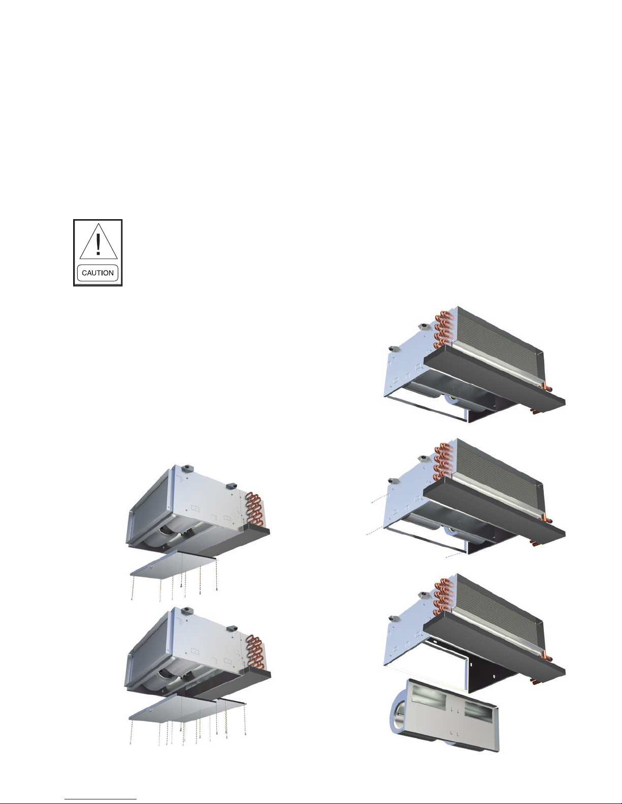
TYPICAL CEILING INSTALLATION
A
SIDE VIEW
Figure 1: Typical ceiling installation
The unit’s drain pan is factory sloped toward the
drain connection when the unit is
installed level and plumb.
4
ENVIRO-TEC
Page 7

DRAIN PAN
Standard drain pans are externally insulated, single wall
galvanized steel and can be equipped with a secondary
drain connection. The HL drain pan is easily removable
for cleaning. See illustration below. Auxiliary drip pan
to catch condensed moisture from valves and piping
must be sloped toward the drain pan.
FORM ET115.24-NOM11 (118)
The condensate drain pan can be removed without re-
quiring common hand tools. The drain pan is secured
to the unit by four sheet metal tabs that slide into four
respective slots on the drain pan.
Prior to removing the drain pan, make sure all
accessories and eld connections have been
appropriately disconnected from the drain pan.
The drain pan can be removed in three steps. First,
push the drain pan engagement lever to unlock the
drain pan from the coil. Next, while continuing to
push the lever, support the weight of the drain pan
and slide the drain pan towards the drain connection.
After the drain pan slides approximately 1.5 inches,
it will be completely disengaged from the coil.
Lastly, support the weight of the drain pan and
safely lower the drain pan for servicing. Reinstall
prior to unit startup.
COILS
All fan coils are available in 2 or 4 pipe congurations.
Heating coils are available in reheat or preheat position.
Heating and cooling coils are available with right, left
or opposite side connections.
Figure 2a
Figure 2b Figure 2c
Verify that the proper types of service are actually
provided to the unit. On units with steam heating
coils, the maximum steam pressure applied to the unit
should never exceed 15 PSIG. The drain piping and
steam trap should be sized and routed to allow for
proper condensate ow. The electrical service to the
unit should be compared to the unit nameplate to verify
compatibility. The routing and sizing of all piping, and
the type and sizing of all wiring and other electrical
components such as circuit breakers, disconnect
switches, etc., should be determined by the individual
job requirements and should not be based on the size
and/or type of connection provided on the equipment.
All installations should be made in compliance with all
governing codes and ordinances. Compliance with all
codes is the responsibility of the installing contractor.
ENVIRO-TEC
Figure 2d
Figure 2a-2d: Typical drain pan removal
5
Page 8

FORM ET115.24-NOM11 (118)
COOLING/HEATING MEDIUM CONNECTIONS
Toxic residues and loose particles
resulting from manufacturing and
eld piping techniques such as joint
compounds, soldering ux, and metal
shavings may be present in the unit
and the piping system. Not for use with
domestic or potable water systems.
Submittals and Product Catalogs detailing unit operation,
controls, and connections should be thoroughly
reviewed BEFORE beginning the connection of the
various cooling and/or heating mediums to the unit.
All accessory valve packages should be installed as
required, and all service valves should be checked for
proper operation.
If coil and valve package connections are to be made
with “sweat” or solder joint, care should be taken to
assure that no components in the valve package are
subjected to a high temperature which may damage seals
or other materials. Many two-position electric control
valves, depending on valve operation, are provided with
a manual-opening lever. This lever should be placed
in the “open” position during all soldering or brazing
operations. Valve bodies should be wrapped with a wet
rag to help dissipate heat encountered during brazing.
Refrigerant systems should be tested with dry nitrogen
rather than air to prevent the introduction of moisture
into the system. In the event that leaking or defective
components are discovered, the Sales Representative
must be notied BEFORE any repairs are attempted.
All leaks should be repaired before proceeding with
the installation.
Figure 3a
Figure 3b
If the valve package connection at the coil is made with
a union, the coil side of the union must be prevented
from twisting (“backed up”) during tightening to prevent
damage to the coil tubing. Over-tightening must be
avoided to prevent distorting the union seal surface
and destroying the union. Due to the diversity of valve
packages for this product, install the valve packages with
no leaks or interference between components during
operation and maintenance. In the case of eld installed
valves and piping, the chilled water valve cluster (or
metering device on DX units) should be installed in
such a way that any dripping or sweating is contained
in the auxiliary drain pan or other device. Valves and
TXV’s should be secured or supported to avoid damage
to coil headers or distributor tubes. All valves, pipes,
and components must be suciently supported to ensure
structural integrity and proper operation of the unit.
All water coils must be protected from
freezing after initial lling with water.
Even if the system is drained, unit coils
may still hold enough water to cause
damage when exposed to temperatures
below freezing.
Figure 3c
Figure 3d
Figure 3a-3d: Typical auxiliary drain pan removal
6
ENVIRO-TEC
Page 9

FORM ET115.24-NOM11 (118)
AUXILIARY DRAIN PANS
Mounted directly to the unit drain pan, AUXILIARY
DRAIN PANS may also be secured by the mounting
holes to eld supports or to the unit coil utilizing pipe
hanger wire, plastic ties, or metal strapping.
After the connections are completed, the system should
then be tested for leaks. Since some components are not
designed to hold pressure with a gas, hydronic systems
should be tested with water.
Prior to removing the auxiliary drain pan, make sure
all accessories have been appropriately disconnected
from the auxiliary drain pan. The auxiliary drain pan
can be removed in three steps. First, remove the two
screws that attached the auxiliary drain pan to the
support bracket near the inlet of the unit. Next, support
the weight of the auxiliary drain pan and slide the
auxiliary drain pan towards the discharge of the unit so
the auxiliary drain pan lip will clear the drain pan lip.
After the auxiliary drain pan slides approximately 0.75
inches, the auxiliary drain pan will be free from the
drain pan. Lastly, support the weight of the auxiliary
drain pan and safely lower for servicing. Reinstall prior
to unit startup.
It should be noted that none of these methods would
adequately protect a coil in the event of power failure.
The safest method of freeze protection is to use glycol
in the proper percent solution for the coldest expected
air temperature.
The manufacturer assumes no responsibility for
undesirable system operation due to improper design,
equipment or component selection, and/or installation of
ductwork, grilles, and other eld supplied components.
ELECTRICAL CONNECTIONS
The unit nameplate lists the unit electrical characteristics
such as the required supply voltage, fan and heater
amperage and required circuit ampacities. The unitwiring diagram shows all unit and eld wiring. Since
each project is dierent and each unit on a project may
be dierent, the installer must be familiar with the
wiring diagram and nameplate on the unit BEFORE
beginning any wiring. This unit is not acceptable for
installation in hazardous/explosive areas.
ELECTRICAL ENCLOSURE
DUCTWORK CONNECTIONS
All ductwork and/or supply and return grilles should
be installed in accordance with the project plans and
specications. If not included on the unit or furnished
from the factory, ENVIRO-TEC supply and return
grilles are available in a variety of types.
Units can be congured from the factory with duct
collars for attaching ductwork. The factory suggests
using galvanized sheet metal ductwork or a exible
canvas attached to the duct collars using sheet metal
screws. Duct connections should follow SMACNA
standards and national and local codes.
All units must be installed in non-combustible areas.
Some models are designed to be connected to duct-work
with a MINIMUM amount of external static pressure.
Consult the approved submittals and the product catalog
for unit external static pressure limitations.
Units provided with outside air for ventilation should
have some form of low temperature protection to
prevent coil freeze-up.
Figure 4: Electrical enclosure
The electrical control enclosure provides access to the
electrical compartment. This compartment houses all
electric heat and control components. Terminal strips
are furnished for simple power and control wiring
connections. Multiple knockouts allow wiring entries
from either side of the compartment.
All components furnished for eld installation, by either
the factory or the controls contractor should be located
and checked for proper function and compatibility. All
internal components should be checked for shipping
damage. After installation and before energizing
the unit, verify voltage and check that all electrical
connections are tight. Electrical connetions should be
periodically checked for tightness.
ENVIRO-TEC
7
Page 10

FORM ET115.24-NOM11 (118)
Any devices such as fan switches or thermostats
that have been furnished from the factory for eld
installation must be wired in strict accordance with the
applicable wiring diagrams. Failure to do so could result
in personal injury or damage to components and will
void all manufacturers’ warranties.
All eld wiring should be done in accordance with
governing codes and ordinances. Any modication of
the unit wiring without factory authorization will result
in voiding of all factory warranties and will nullify any
agency listings.
The manufacturer assumes no responsibility for any
damages and/or injuries resulting from improperly eld
installed or wired components.
This unit is listed to UL/CSAS standards. All
modications to line voltage wiring must be performed
in accordance with the NEC and inspected by ETL to
maintain product listing. Unauthorized modication to
any wiring may impact unit performance and void ETL
listing and/or product warranty.
TELESCOPING BOTTOM PANEL
The telescoping bottom panel allows for fully recessing
the unit while permitting service access into the ceiling
plenum. The architectural ceiling panel is nished with
a durable powder coat paint.
Portions of the inlet louver not directly
below unit inlet may require covering
in the field on applications where
inltration of ceiling plenum air into
space is undesired. Telescoping skirt
and collar assembly must be field
adjusted to assure a proper t between
lter frame and louvered inlet panel
assembly. Refer to assembly submittal
drawings for specic dimensions.
8
ENVIRO-TEC
Page 11

FORM ET115.24-NOM11 (118)
MODEL HLP HORIZONTAL FAN COIL
Optional Telescoping Bottom Panel Assembly, Typical Installation Instructions
Drawings are subject to change without notice. Refer to www.enviro-tec.com for current submittal drawings.
FHP UNIT CHASSIS
10 1/2"
264
7 [178]
10 1/2 [267]
AIR
OPEN THIS
PANEL FIRST
FINISHED
CEILING LINE
TYPICAL INSTALLATION METHODS
CEILING GRID
"T" BAR
ACOUSTIC FIBRE
CEILING TILE
NOTE: CEILING "T" BAR GRID MAY NOT SUPPORT TELESCOPING
BOTTOM PANEL ASSEMBLY. BOTTOM PANEL ASSEMBLY
MAY REQUIRE INDEPENDENT SUPPORT.
TELESCOPING BOTTOM
PANEL FRAME EXTRUSION
SOLID OR LOUVERED
BOTTOM PANEL
SUSPENDED GRID/TILE CEILING SYSTEM
INLET COLLAR INSTALLATION
SHIM AS
REQUIRED
TELESCOPING BOTTOM
PANEL FRAME EXTRUSION
SHT MTL OR WOOD
SCREW AS REQUIRED,
SEE NOTES 4 & 6
SOLID OR LOUVERED
BOTTOM PANEL
SHT MTL OR WOOD
SCREW AS REQUIRED,
SEE NOTES 4 & 6
STUD/DRYWALL CEILING SYSTEM
SCREW THE TELESCOPING PANEL TO
THE CHASSIS 2 SCREWS BOTH SIDE
METAL OR WOOD
CEILING STUD
DRYWALL
CEILING
SHIM AS
REQUIRED
TABLE 1: TELESCOPING BOTTOM PANEL WEIGHTS (LBS./KG)
DESCRIPTION
Telescoping bottom panel 10 [5] 11 [5] 12 [5] 14 [6] 16 [7] 17 [8] 20 [9] 21 [10]
ENVIRO-TEC
02 03 04 06 08 09 10 12
UNIT SIZE
9
Page 12

SERVICE AND CLEARANCE REQUIREMENTS
FORM ET115.24-NOM11 (118)
HORIZONTAL, LOW PROFILE EXPOSED UNITS
10
ENVIRO-TEC
Page 13

FORM ET115.24-NOM11 (118)
SERVICE AND CLEARANCE REQUIREMENTS: HEIGHT RESTRICTED APPLICATION
CORNER PANELS
SHOWN ROTATED 90°
0" CLEARANCE BETWEEN UNIT AND STRUCTURE
UNIT
INSTALLED
HALF
OPENED
FULLY
OPENED
CORNER PANELS ROTATE
ABOUT PIVOT POINT
CORNER PANELS ROTATED 90°
CAN BE LIFTED AND REMOVED
11" [279] MIN
REQUIRED CLEARANCE
BESIDE UNIT
REQUIRED CLEARANCE
HORIZONTAL, LOW PROFILE EXPOSED UNITS
0"
ABOVE UNIT
4" [102] MIN
REQUIRED CLEARANCE
BELOW UNIT
ENVIRO-TEC
11
Page 14

FORM ET115.24-NOM11 (118)
SERVICE AND CLEARANCE REQUIREMENTS: WIDTH RESTRICTED APPLICATION
CORNER PANELS
SHOWN LIFTED AND
ROTATED 5°
UNIT
INSTALLED
HALF
OPENED
FULLY
OPENED
CLEARANCE BETWEEN
3"
[76]
STRUCTURE AND UNIT
3"
[76]
LIFT AND ROTATE CORNER PANEL
OFF OF PIVOT POINT
ABIDE BY APPLICABLE
CODES AND STANDARDS
REGUARDING ACCESS
FOR ELECTRICAL OR
PLUMBING COMPONENTS
1" [25] MIN
REQUIRED CLEARANCE
ABOVE UNIT
3" [76] MIN
REQUIRED CLEARANCE
BESIDE UNIT
(PANEL REMOVAL
REQUIRED FOR
ELECTRICAL ACCESS)
HORIZONTAL, LOW PROFILE EXPOSED UNITS
12
DROP CORNER PANELS
STRAIGHT DOWN
ENVIRO-TEC
Page 15

FORM ET115.24-NOM11 (118)
8"
206
8 1/2"
216
OPTIONAL AUXILIRY
DRIP PAN
3"
77
SUPPLY AIR
OPENIG WIDTH
R10 1/2"
264
CONTROL ENCLOSURE
SEE NOTE 9
FRONT VIEW
LH SHOWN RH
OPPOSITE
22"
559
TOP VIEW
SERVICE AND CLEARANCE REQUIREMENTS: EXTERNAL SPACE REQUIREMENTS
TOP VIEW
22"
559
OPTIONAL
SIDE ACCESS
CONTROL ENCLOSURE
SEE NOTE 5
8"
1"
25
204
SUPPLY AIR
OPENING WIDTH
FRONT VIEW
OPTIONAL AUXILIARY
10 1/2"
267
AIR FILTER CLEARANCE
HORIZONTAL, LOW PROFILE PLENUM AND FREE RETURN
NOTES:
1. All chilled water piping that projects beyond the condensate pan or the optional auxiliary drip pan
must be field insulated by others.
2. Auxiliary drip pan shown above is optional, and is mounted on the outlet side of the drain pan.
3. Drain pan is installed with the outlet tube(s) on cooling coil connection end of coil on 4-pipe units with
optional opposite end connection.
4. Dimensions shown on this drawing apply to standard CW and HW valve packages. Refer to the
Piping Package Catalog for valve package code details. Contact factory for details on valve packages
using non-standard or customer furnished components.
5. Provide sufficient clearance to access electrical components and comply with all applicable codes and
ordinances.
8 1/2"
216
DRIP PAN
ENVIRO-TEC
13
Page 16

SECTION TWO - START-UP
FORM ET115.24-NOM11 (118)
GENERAL
Before beginning any start-up operation, the startup personnel should familiarize themselves with the
unit, options and accessories, and control sequence to
understand the proper system operation. All personnel
should have a good working knowledge of general
start-up procedures and have the appropriate start-up
and balancing guides available for consultation.
The initial step in any startup operation should be a nal
visual inspection. All equipment, plenums, duct-work,
and piping should be inspected to verify that all systems
are complete and properly installed and mounted, and
that no debris or foreign articles such as paper or drink
cans are left in the units or other areas. Each unit should
be checked for loose wires, free blower wheel operation,
and loose or missing access panels or doors. Except as
required during start-up and balancing operations, no
fan coil units should be operated without all the proper
ductwork attached, supply and return grilles in place,
and all access doors and panels in place and secure.
A clean lter of the proper size and type must also be
installed. Failure to do so could result in damage to the
equipment or building and furnishings, and/or void all
manufacturers’ warranties.
Fan coils are not intended for temporary heat/cool
or ventilation. Units are not designed or equipped to
operate in dusty construction environments. Operation
of the units in conditions outlined above could result in
damage to the equipment or building and furnishings
and/or void all manufacturer’s warranties.
COOLING/HEATING SYSTEM
Prior to the water system start-up and balancing, the
chilled/hot water systems should be ushed to clean
out dirt and debris, which may have collected in the
piping during construction. During this procedure,
all unit service valves must be in the closed position.
This prevents foreign matter from entering the unit and
clogging the valves and metering devices. Strainers
should be installed in the piping mains to prevent this
material from entering the units during normal operation.
During system filling, air venting from the unit is
accomplished by the use of the standard manual, or
optional automatic, air vent tting installed on the coil.
In the case of the manual air vent tting, the screw
should be turned counterclockwise no more than 1-½
turns to operate the air vent. Automatic air vents may
be unscrewed one turn counterclockwise to speed
initial venting but should be screwed in for automatic
venting after start-up operations. Check to ensure that
no leaks are prevalent at the coils, coil connections,
piping packages, etc.
The air vent provided on the unit is not
intended to replace the main system air
vents and may not release air trapped
in other parts of the system. Inspect
the entire system for potential air
traps and vent those areas as required,
independently. In addition, some
systems may require repeated venting
over a period of time to properly
eliminate air from the system.
AIR SYSTEM BALANCING
All duct-work must be complete and connected, and all
grilles, lters, access doors and panels must be properly
installed to establish actual system operating conditions
BEFORE beginning air balancing operations.
Each individual unit and attached duct-work is a unique
system with its own operating characteristics. For this
reason, air balancing is normally done by balance
specialists who are familiar with all procedures required
to properly establish air distribution and fan system
operating conditions. These procedures should not be
attempted by unqualied personnel. Some selections
may require air balancing in the eld.
After the proper system operation is established,
the actual unit air delivery and the actual fan motor
amperage draw for each unit should be recorded in
a convenient place for future reference such as the
inspection, installation, & start-up check sheet, a copy
of which is provided on the back of this manual. Contact
the Sales Representative or the factory for additional
copies of this sheet.
14
ENVIRO-TEC
Page 17

MOTOR AND FAN DATA
TABLE 2A: PSC MOTORS, MODEL HLP, HLE
FORM ET115.24-NOM11 (118)
UNIT
SIZE
PSC MOTOR HP
(QTY)
02 (1) 1/20
# OF FANS FAN SPEED WATTS
3
1
High 55
2
115 VOLTS 208/230 VOLTS 277 VOLTS
AMPS
1
AMPS
1
AMPS
0.6 N/A N/AMedium 40
Low 36
03 (1) 1/20
3
1
High 61
0.6 N/A N/AMedium 45
Low 40
High 75
04 (1) 1/20 2
0.8 0.4 0.5Medium 65
Low 58
High 80
06 (1) 1/20 2
0.8 0.4 0.5Medium 68
Low 56
High 122
08 (1) 1/10 2
1.1 0.6 0.5Medium 83
Low 66
High 127
09 (1) 1/10 2
1.1 0.6 0.5Medium 86
Low 66
High 148
10 (2) 1/20 4
1.6 0.8 1Medium 128
Low 110
High 160
12 (2) 1/20 4
1.6 0.8 1Medium 139
Low 115
NOTES:
1. Motor electrical data is nameplate data.
2.WattsarebasedonanHLPwithPSCmotor,3rowcoil,12FPI,1"throwawaylter,0.05"ESPat115V.
3. PSC motors are not available in 208-277V on SZ02 and SZ03.
4. Motor data is subject to change and should not be used for submittal purposes. Refer to Web-Select submittal for actual ratings.
1
TABLE 2B: PSC MOTORS, MODEL HLF
UNIT
PSC MOTOR HP
SIZE
(QTY)
02 (1) 1/20
# OF FANS FAN SPEED WATTS
3
1
High 55
2
Low 36
03 (1) 1/20
3
1
High 61
Low 40
High 75
04 (1) 1/20 2
Low 58
High 121
06 (1) 1/10 2
Low 66
High 224
08 (1) 1/6 2
Low 66
High 230
09 (1) 1/6 2
Low 67
High 226
10 (2) 1/10 4
Low 128
High 248
12 (2) 1/10 4
Medium 171
Low 133
NOTES:
1. Motor electrical data is nameplate data.
2.WattsarebasedonanHLFwithPSCmotor,3rowcoil,12FPI,1"throwawaylter,0.05"ESPat115V.
3. PSC motors are not available in 208-277V on SZ02 and SZ03.
4. Motor data is subject to change and should not be used for submittal purposes. Refer to Web-Select submittal for actual ratings.
115 VOLTS 208/230 VOLTS 277 VOLTS
AMPS
1
AMPS
1
AMPS
0.6 N/A N/AMedium 40
0.6 N/A N/AMedium 45
0.8 0.4 0.5Medium 65
1.1 0.6 0.5Medium 84
2.1 1.1 0.9Medium 140
2.1 1.1 0.9Medium 139
2.2 1.2 1Medium 154
2.2 1.2 1
1
ENVIRO-TEC
15
Page 18

TABLE 3: EC MOTORS
UNIT
SIZE
02
03
04
06
08
09
10
12
FAN
SPEED
High
Low 14 / 26
High
Low 16 / 33
High
Low 21 / 41
High
Low 36 / 62
High
Low 31 / 62
High
Low 39 / 77
High
Low 54 / 104
High
Low 56 / 105
EC MOTOR
HP (QTY)
(1) 1/4 1
(1) 1/4 1
(1) 1/4 2
(1) 1/4 2
(1) 1/4 2
(1) 1/4 2
(2) 1/4 4
(2) 1/4 4
# OF
FANS
WATTS
(STD/HS)
32 / 45
35 / 59
50 / 75
104 / 132
91 / 122
119 / 182
142 / 207
143 / 209
FORM ET115.24-NOM11 (118)
1,3
3-SPEED
(STD/HS)
AMPS
2-10VDC
3-SPEED
(STD/HS)
2
115 VOLTS 208/230 VOLTS 277 VOLTS
3-SPEED
(STD/HS)
0.7 / 1.0 0.9 0.5 / 0.6 0.5 0.4 / 0.5 0.5Medium 21 / 36
1.0 / 1.5 1.1 0.6 / 0.9 0.7 0.5 / 0.8 0.6Medium 23 / 43
1.5 / 1.8 1.2 0.9 / 1.1 0.8 0.8 / 0.9 0.6Medium 33 / 56
2.6 / 3.1 2.0 1.6 / 1.9 1.2 1.3 / 1.6 1.0Medium 62 / 89
2.3 / 2.9 2.0 1.4 / 1.7 1.2 1.2 / 1.5 1.0Medium 54 / 90
3.7 / 4.5 2.7 2.3 / 2.7 1.6 1.9 / 2.3 1.4Medium 72 / 116
3.9 / 5.1 3.1 2.3 / 3.1 1.9 2.0 / 2.6 1.6Medium 91 / 139
3.2 / 4.5 3.5 2.0 / 2.7 2.1 1.6 / 2.3 1.8Medium 92 / 152
2-10VDC
2-10VDC
NOTES:
1. Motor electrical data is nameplate data.
2.WattsarebasedonanHLPwith3-speedECmotor,3rowcoil,12FPI,1"throwawaylter,0.05"ESPat115V.
3. For neutral conductor sizing, multiply AMPS by 1.73.
4. Motor data is subject to change and should not be used for submittal. Refer to unit submittal for actual ratings.
WATER SYSTEM BALANCING
A complete knowledge of the hydronic system, its
components, and controls is essential to proper water
system balancing and this procedure should not be
attempted by unqualied personnel. The system must
be complete and all components must be in operating
CONTROLS OPERATION
Before proper control operation can be veried all other
systems must be in proper operation. The correct water
and air temperatures must be present for the control
function being tested. Some controls and features are
designed to not operate under certain conditions.
condition BEFORE beginning water system balancing
operations.
A wide range of controls and electrical options and
accessories may be used with the equipment covered
Each hydronic system has different operating
characteristics depending on the devices and controls
in the system. The actual balancing technique may vary
from one system to another.
in this manual. Consult the approved unit submittals,
order acknowledgement, and other manuals for detailed
information regarding each individual unit and its
controls. Since controls and features may vary from
one unit to another, care should be taken to identify
After the proper system operation is established, the
appropriate system operating conditions such as various
water temperatures and ow rates should be recorded
in a convenient place for future reference.
the controls to be used on each unit and their proper
control sequence. Information provided by component
manufacturers regarding installation, operation, and
maintenance of their individual controls is available
upon request.
Before and during water system balancing, conditions
may exist which can result in noticeable water noise
or undesired valve operation due to incorrect system
pressures. After the entire system is balanced, these
conditions will not exist on properly designed systems.
16
ENVIRO-TEC
Page 19
FORM ET115.24-NOM11 (118)
SECTION THREE - NORMAL OPERATION & PERIODIC MAINTENANCE
GENERAL
Each unit on a job will have its own unique operating
environment and conditions that may dictate a
maintenance schedule for that unit that is dierent
from other equipment on the job. A formal schedule of
regular maintenance and an individual unit log should
be established and maintained. This will help to achieve
the maximum performance and service life of each unit
on the job.
Information regarding safety
precautions contained in the preface
at the beginning of this manual should
be followed during any service and
maintenance operations.
For more detailed information concerning service
operations, consult your Sales Representative or the
Factory.
MOTOR/BLOWER ASSEMBLY
The type of fan operation is determined by the control
components and their method of wiring, and may vary
from unit to unit. Refer to the wiring diagram for each
unit for that unit’s individual operating characteristics.
Motors are permanently lubricated, PSC or EC type and
do not require eld lubrication.
FAN DECK
The fan assembly is easily removed from the unit
without disconnecting the ductwork for service access
to motors and blowers at, or away from the unit.
Should the assembly require more extensive service,
the motor/ blower assembly may be removed from the
unit to facilitate such operations as motor or blower
wheel/housing replacement, etc. Dirt and dust should
not be allowed to accumulate on the blower wheel or
housing. This can result in an unbalanced blower wheel
condition that can damage a blower wheel or motor.
The wheel and housing may be cleaned periodically
using a vacuum cleaner and a brush taking care not to
dislodge the factory balancing weights on the blower
wheel blades.
Figure 6a
Figure 5a
Figure 5b
Figure 5a-5b: Bottom panel removal
ENVIRO-TEC
Figure 6b
Figure 6c
Figure 6a-6c: Fan deck removal
17
Page 20

COIL
Coils may be cleaned in place by removing the motor/
blower assemblies and brushing the entering air face
between ns with a soft brush parallel to ns. Do not
brush perpendicular to n orientation as damage may
occur. Brushing should be followed by cleaning with a
vacuum cleaner. If a compressed air source is available,
the coil may also be cleaned by blowing air through the
coil ns from the leaving air face. Vacuuming should
again follow this. Units provided with the proper type
of air lters, replaced regularly, may require periodic
coil cleaning.
FORM ET115.24-NOM11 (118)
ELECTRICAL WIRING & CONTROLS
The electrical operation of each unit is determined by
the components and wiring of the unit and may vary
from unit to unit. Consult the wiring diagram for the
actual type and number of controls provided on each
unit. The integrity of all electrical connections should be
veried at least twice during the rst year of operation.
Afterwards, all controls should be inspected regularly
for proper operation. Some components may experience
erratic operation or failure due to age. Wall thermostats
may also become clogged with dust and lint and should
be periodically inspected and cleaned to provide reliable
operation.
When replacing any components such as fuses,
contactors, or relays, use only the exact type, size, and
voltage component as furnished from the factory. Any
deviation without factory authorization could result
in personnel injury or damage to the unit and will
void all factory warranties. All repair work should be
done in such a manner as to maintain the equipment in
compliance with governing codes and ordinances or
testing agency listings.
ELECTRIC RESISTANCE HEATER ASSEMBLY
Electric resistance heaters typically require no normal
periodic maintenance when unit air lters are changed
properly. Other conditions and equipment may aect the
operation and service life in the system. The two most
important operating conditions for an electric heater are
proper airow and proper supply voltage. High supply
voltage and/or poorly distributed or insucient airow
over the element will result in element overheating. This
condition may result in the heater cycling on the high
limit thermal cutout. Open wire type heaters provided
have an automatic reset switch with a back-up high
limit thermal switch. Automatic reset switches are as
the name implies; they reset automatically after the
heater has cooled down. The high limit thermal cutout
device is a manual reset safety device. With proper
unit application and during normal operation, the high
limit thermal cutout will not operate. This device only
operates when some problem exists. ANY condition
that causes high limit cutout MUST be corrected
immediately. Once the high limit trips, it may be reset
once the unit has cooled down. Refer to troubleshooting
section for high limit reset instructions. High supply
voltage also causes excessive amperage draw and may
result in tripping of the circuit breaker or blowing of
the fuses on the incoming power supply.
More specific information regarding the use and
operating characteristics of the standard controls oered
by this manufacturer is contained in other manuals.
VALVES & PIPING
No formal maintenance is required on the valve package
components most commonly used with fan coil units
other than a visual inspection for possible leaks in the
course of other normal periodic maintenance. In the
event that a valve should need replacement, the same
precautions taken during the initial installation to protect
the valve package from excessive heat should also be
used during replacement. If a strainer is ordered with
the unit the strainer must be cleaned periodically along
with other scheduled maintenance. In some cases, the
valve actuator may fail and usually can be replaced
without removing valve body from piping.
18
ENVIRO-TEC
Page 21

FORM ET115.24-NOM11 (118)
FILTERS, THROWAWAY
The type of throwaway lter most commonly used on
fan coil units should be replaced on a regular basis.
The time interval between each replacement should be
established based on regular inspection of the lter and
should be recorded in the log for each unit. Refer to the
Figure 7a
chart below for recommended lter size for each product
type and size. If the replacement lters are not purchased
from the factory, the lters used should be the same type
and size as that furnished from or recommended by the
factory. Consult the factory for applications using lter
types other than the factory standard or optional product.
Figure 7c
Figure 7b
Figure 7d
Figure 7a-7d: Filter removal
ENVIRO-TEC
19
Page 22

DRAIN
The drain should be checked before initial start-up and
at the beginning of each cooling season to assure that
the lines are clear. If it is clogged, steps should be taken
to clear the debris so that condensate will ow easily.
Periodic checks of the drain should be made during the
cooling season to maintain a free owing condensate.
TABLE 4: FACE AREA, FREE AREA AND FILTER SIZES
FORM ET115.24-NOM11 (118)
Should the growth of algae and/or bacteria be a
concern, consult an air conditioning and refrigeration
supply organization familiar with local conditions for
chemicals available to control these agents. If cleaners
are used, they should be compatible with the materials
of construction for the coil, drain pan, and condensate
pump (if applicable).
UNIT
COIL FACE
SIZE
02 0.89 [0.08] 0.83 [0.08] 0.61 [0.06] 1.17 [0.11]
03 1.07 [0.1] 0.83 [0.08] 0.61 [0.06] 1.39 [0.13]
04 1.35 [0.13] 1.25 [0.12] 0.92 [0.09] 1.77 [0.16]
06 1.72 [0.16] 1.45 [0.14] 1.07 [0.1] 2.26 [0.21]
08 2.11 [0.2] 1.87 [0.17] 1.38 [0.13] 2.77 [0.26]
09 2.35 [0.22] 2.08 [0.19] 1.53 [0.14] 3.08 [0.29]
10 2.89 [0.27] 2.7 [0.25] 1.99 [0.18] 3.79 [0.35]
12 3.33 [0.31] 3.12 [0.29] 2.3 [0.21] 4.38 [0.41]
AREA
RETURN AIR
GRILLE FREE
AREA
SUPPLY AIR
GRILLE FREE
AREA
FILTER FACE
AREA (REAR
RETURN)
NOTES:
1. Face and free areas are in square feet [square meters].
2. Filter sizes are in inches [millimeters].
3. Free area of ENVIRO-TEC® Model HLE and Telescoping
Bottom Panel return grilles.
4. Free area of ENVIRO-TEC® Model HLE supply grille and
minimum free area allowable for a supply grille supplied
by others.
NOMINAL FILTER SIZES
(REAR RETURN)
16 x 10.5 x 1
[406 x 267 x 25]
19 x 10.5 x 1
[483 x 267 x 25]
24.25 x 10.5 x 1
[616 x 267 x 25]
31 x 10.5 x 1
[787 x 267 x 25]
(2) 19 x 10.5 x 1
[483 x 267 x 25]
(1) 20, (1) 22.25 x 10.5 x 1
[508, 565 x 267 x 25]
(2) 26 x 10.5 x1
[660 x 267 x 25]
(1) 20, (1) 40 x 10.5 x 1
[508, 1016 x 267 x 25]
FILTER FACE AREA
(BOTTOM RETURN)
1.06 [0.1]
1.25 [0.12]
1.60 [0.15]
2.05 [0.19]
2.51 [0.23]
2.79 [0.26]
3.43 [0.32]
3.96 [0.37]
NOMINAL FILTER SIZES
(BOTTOM RETURN)
16 x 9.25 x 1
[406 x 235 x 25]
19 x 9.25 x 1
[483 x 235 x 25]
24.25 x 9.25 x 1
[616 x 235 x 25]
31 x 9.25 x 1
[787 x 235 x 25]
(2) 19 x 9.25 x 1
[483 x 235 x 25]
(1) 20, (1) 22.25 x 9.25 x 1
[508, 565 x 235 x 25]
(2) 26 x 9.25 x1
[660 x 235 x 25]
(1) 20, (1) 40 x 9.
[508, 1016 x 235 x 25]
25 x 1
20
ENVIRO-TEC
Page 23
FORM ET115.24-NOM11 (118)
CONDENSATE WATER PUMP
SAFETY WARNING
Risk of electric shock. Make certain
that the entire power supply to the
unit/system is disconnected before
attempting to install, service or remove
this component.
General information
The high performance water condensate pump is
suitable for units up to 5.6 tons (67 kBtu - 20 kW). The
piston technology is specically designed for removing
condensate from air conditioning systems. It is fully
reliable, in any kind of environment and its operating
sound level will remain silent <23 dB whatever the
volume of condensate.
Technical specications
Operation
voltage
Operating
temperature
Thermal
protection
(overheating)
Max head 23 Ft
Max suction
lift
Replacement instructions
a. Disconnect the main power on the unit.
b. For wiring connection to unit, refer to unit wire
diagram.
c. For accessories, assembly, and internal wire
connections, refer to condensate water pump
manufacturer instructions.
d. Locate the two alignment holes for the water pump
bracket, right bottom corner of the unit.
e. Attach pump to bracket and mount it to unit with
two screws. (See Figure 1)
f.
Complete all assembly prior to mounting pump cover.
g. Connect tubing. Once all of the connections are
made, reconnect the main power of the unit.
120V +/- 10% ~50/60Hz – 4.7W
208 - 230V +/- 10% ~50/60Hz – 4.7W
Max 257 °F (125 °C) auto-reset
257 °F (125 °C) auto-reset
16.52 Ft
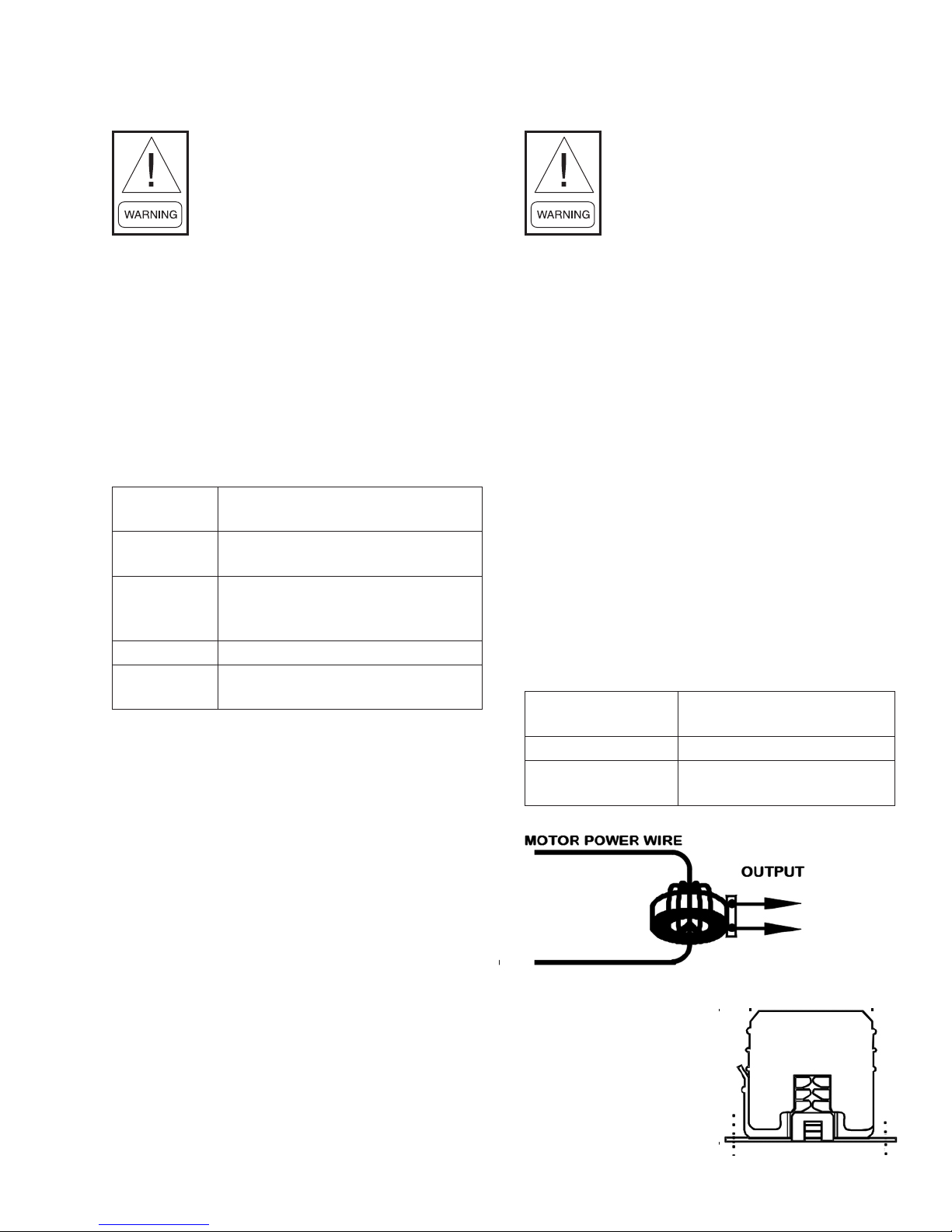
CURRENT SWITCH DEVICE
SAFETY WARNING
The Current Switch is intended to
provide an input to equipment under
normal operating conditions. Where
failure or malfunction of the Current
Switch could lead to personal injury
or property damage to the controlled
equipment or other property, additional
precautions must be designed into
the control system. Incorporate and
maintain other devices, such as
supervisory or alarm systems or safety
or limit controls, intended to warn of or
protect against failure or malfunction
of the Current Switch.
General information
The Current Switch is a non-intrusive device that
detects current owing through the motor power wire.
Completely self-powered, the Current Switch draws its
power from current induced by the power wire of the
motor being monitored. Fig. 5 shows the current switch
wire connections. It is panel mounted with two screws
inside the main electrical enclosure; refer to g. 6.
Technical specications
Wire size
Status output Switch normally open
Switch load
capacity
Figure 9 Current Switch in circuit
2.1–0.6 mm (12–22 AWG)
diameter recommended
1 A at 30 VAC/42 VDC
maximum
ENVIRO-TEC
Figure 10 Current Switch mounting
21
Page 24

DIFFERENTIAL AIR PRESSURE SWITCH
FORM ET115.24-NOM11 (118)
General information
This accessory is a dierential pressure switch with
a normally-open (NO) dry contact that is factory
calibrated to close at a dierential pressure of 0.15
inches of water or greater. The switch measures the
pressure dierential between the unit’s fan section and
the environmental pressure outside the unit. When the
lter is suciently clogged or dirty, dierential pressure
will rise and the switch will close.
Technical specications
Electrical
Initial resistance <500mW
Rating
3.15ma @ 125VAC
10-20ma @ 5-24VDC
Adjustable set point ranges in H2O
Ranges
In H2O
Min. Max. Proof
0.10 0.50 5.0
Functional
Operating positing
Operating temp.
Diaphragm vertical, barbed
ttings horizontal
-40 °F to 140 °F
(-40 °C to 60 °C)
Installation
Assembly
The dierential air pressure switch is mounted inside
the unit with double sided tape behind the lter retention
tab. (See gure 12a). Instructions for commissioning or
replacing the dierential air pressure switch:
a. Disconnect main power on the unit.
b. Secure dierential air pressure switch on the lter
retention tab using double sided tape. Position
the pressure port (marked with “+”) outside the
chassis exposed to the environment. The vacuum
port should extend inside the chassis and be open
to the unit’s fan section. (See gure 12b.)
c. Wire the NO relay using .187 quick connectors.
d. Verify all connections before reconnecting main
power.
General measurements: Pressure Switch
Figure 11
Figure 12a
Figure 12b
22
ENVIRO-TEC
Page 25

FORM ET115.24-NOM11 (118)
DISCHARGE AIR SENSOR
General Information
The Discharge Air Sensor is a nickel 1kΩ sensor probe
with a anged mounting bracket (no enclosure).
Suggested Location
The Discharge Air Sensor is tted to the side of the coil
ange in the holes provided for this accessory. (See
Figure 13.)
Replacement instructions
a. Disconnect the main power on the unit.
b. Mount the Discharge Air Sensor with two screws
as shown. (See Figure 13.)
c. Secure the plenum-rated cable into control
enclosure using the control enclosure knockouts
accordingly.
d. Once all of the connections are made, reconnect
the main power.
LOW TEMPERATURE CUTOUT CONTROL
General information
This low temperature device will de-energize the system
if the operating conditions begin to approach freezing
(as water freezes it expands and will rupture the coil
barrel tubes). The function of this low temperature
device is to cycle a SPST switch in response to changes
of temperature. Refer to g. 4 to locate the device on
your unit.
Adaptable cold control
Range of adjustments are limited to the rotation of the
dial for the required temperature set point needed.
Altitude correction chart
(CW TURNS OF RANGE SCREW)
Feet Turns Feet Turns
2000 35 8000 215
4000 100 9000 250
6000 160 10000 270
Electrical ratings
WARNING: Do not exceed the
maximum wattage, ratings, or
published operating conditions as
noted below.
Figure 13
ENVIRO-TEC
23
Page 26

Replacement instructions
The primary purpose of the low limit cutout is to prevent
the coil from freezing. Therefore, before mounting the
control, you need to consider all possible factors that
help protect the coil from freezing. It is important that
the cutout capillary not be cut, kinked or pinched in
mounting to unit elements. Also, ensure tubing clamps
and wells are of compatible material with the control
sensing element to prevent corrosion.
a. Disconnect the main power on the unit.
b. Locate the two inner mounting holes between
control enclosure and coil.
c. Use two supplied screws to mount the low
temperature cutout in place.
d. Work your way back up to the bellows, stringing
the sensing element throughout the drain pan,
e. Position the sensing element horizontally across
the face of the coil, and secure the sensing element
with mount tape and wire tie. (See Figure 14.)
f. Wire the NC relay using the .250 quick connectors.
g. Once all of the connections are made, reconnect
the main power of the unit.
FORM ET115.24-NOM11 (118)
Figure 14
TABLE 5: UNIT WEIGHT DATA (LBS./KG)
COMPONENT
HLF BASE UNIT 22 [10] 25 [12] 33 [15] 43 [20] 53 [24] 60 [27] 74 [34] 83 [38]
HLP BASE UNIT 24 [11] 28 [13] 36 [16] 47 [21] 58 [26] 65 [30] 81 [37] 91 [41]
HLE BASE UNIT 56 [25] 63 [29] 75 [34] 92 [42] 108 [49] 118 [54] 141 [64] 158 [72]
1 ROW - DRY 6 [3] 7 [3] 8 [4] 10 [4] 11 [5] 13 [6] 15 [7] 17 [8]
1 ROW - WET 8 [4] 9 [4] 10 [4] 12 [5] 13 [6] 15 [7] 17 [8] 19 [9]
2 ROW - DRY 7 [3] 8 [4] 10 [4] 12 [5] 14 [6] 16 [7] 19 [9] 22 [10]
2 ROW - WET 9 [4] 10 [5] 12 [5] 14 [6] 17 [8] 19 [8] 23 [10] 27 [12]
3 ROW - DRY 8 [4] 10 [4] 12 [5] 14 [6] 17 [8] 19 [9] 23 [10] 26 [12]
3 ROW - WET 10 [5] 12 [5] 15 [7] 17 [8] 21 [10] 23 [10] 28 [13] 32 [14]
COIL
ROWS
4 ROW - DRY 9 [4] 11 [5] 13 [6] 17 [8] 20 [9] 22 [10] 27 [12] 30 [14]
4 ROW - WET 13 [6] 15 [7] 18 [8] 22 [10] 26 [12] 28 [13] 34 [15] 38 [17]
5 ROW - DRY 11 [5] 13 [6] 15 [7] 19 [9] 23 [10] 25 [11] 30 [14] 35 [16]
5 ROW - WET 17 [8] 19 [8] 22 [10] 26 [12] 31 [14] 33 [15] 39 [18] 45 [20]
6 ROW - DRY 12 [5] 14 [6] 17 [8] 21 [10] 26 [12] 28 [13] 34 [16] 39 [18]
6 ROW - WET 19 [9] 21 [10] 25 [11] 29 [13] 36 [16] 38 [17] 45 [21] 51 [23]
02 03 04 06 08 09 10 12
UNIT SIZE
24
ENVIRO-TEC
Page 27

CONDENSATE FLOAT SWITCH INSTALLATION
FORM ET115.24-NOM11 (118)
Ensure oat switch assembly is rmly secured to the
bracket. Ensure top of oat is below rim of pan. Switch
will trip when the water level reaches a point even with
top of oat when oat is in down position. Sensitivity
may be adjusted by threading switch assembly
downward out of bracket if necessary.
Test switch by lifting oat with unit on. Unit should
stop running if switch is correctly wired. Test switch
sensitivity by lling pan and conrm switch stops unit
before pan overows.
Supplier’s install instructions
1. Disconnect power to unit at main panel.
2. Clip switch bracket onto side of pan at low end
and press rmly into place ensuring switch wires
are positioned up ensure oat moves freely.
3. Secure bracket into side of pan using self-tapping
sheet metal screw through upper hole in bracket.
4. Ensure oat switch assembly is rmly secured
to bracket. Ensure top of oat is below rim of
pan. Switch will trip when water level reaches
a point even with top of oat (when oat is in
down position). Sensitivity may be adjusted by
threading switch assembly downward out of
bracket if necessary.
5. Ensure wiring matches the wiring diagram
provided with the unit.
6. Test switch by lifting oat with unit on. Unit
should stop running if switch is correctly wired.
7. Test switch sensitivity. Fill pan and conrm that
switch stops unit before pan overows.
8. Place warning sticker on air handler or condenser
unit.
Figure 15a: Drain pan oat switch installed
Figure 15b: Drain pan oat switch diagram
ENVIRO-TEC
25
Page 28

REPLACEMENT PARTS
Factory replacement parts should be used wherever
possible to maintain the unit performance and
operating characteristics and the testing agency listings.
Replacement parts may be purchased through the local
Sales Representative.
Contact the local Sales Representative before attempting
any unit modications. Any modications not authorized
by the factory could result in personnel injury and
damage to the unit and could void all factory warranties
and regulatory listings.
When ordering parts, the following information must be
supplied to ensure proper part identication:
1. Complete unit model number
2. Unit hand connection (right or left hand) while
facing the direction of airow at the inlet
3. Complete part description including any numbers.
FORM ET115.24-NOM11 (118)
On warranty replacements, in addition to the information
previously listed, the project CO # that appears on
the unit nameplate, is required. Contact local Sales
Representative and refr to warranty policy.
All equipment and components sold through the Parts
Department are warranted under the same conditions as
the standard manufacturer’s warranty with the exception
that the warranty period is 12 months.
26
ENVIRO-TEC
Page 29

SECTION FOUR - INSPECTION & START-UP CHECKLIST
RECEIVING & INSPECTION
FORM ET115.24-NOM11 (118)
Unit received undamaged
q
Unit arrangement/hand correct
q
HANDLING & INSTALLATION
Unit mounted level & square
q
Proper electrical service provided
q
Proper service switch/disconnect provided
q
Proper chilled water line size to unit
q
Proper refrigerant line sizes to unit
q
Proper steam condensate trap on return line
q
All services to unit in code compliance
q
COOLING/HEATING CONNECTIONS
Protect Valve Package Components From Heat
q
Connect Field Piping To Unit
q
Install Drain Line & Traps As Required
q
Install Condensate Pan under Piping as Required
q
Unit received complete as ordered
q
Unit structural support complete & correct
q
Proper access provided for unit & accessories
q
Proper overcurrent protection provided
q
Proper hot water line to unit
q
Proper steam line sizes to unit
q
Proper steam supply pressure to unit (15psi max)
q
All shipping screws & braces removed
q
Mount valve packages
q
Pressure test all piping for leaks
q
Insulate all piping as required
q
DUCTWORK CONNECTIONS
Install Ductwork, Fittings & Grilles As Required
q
Control Outside Air For Freeze Protection
q
ELECTRICAL CONNECTIONS
Refer to unit wiring diagram
q
All eld wiring in code compliance
q
UNIT STARTUP
General visual unit & system inspection
q
Record ambient temperature
q
Close all unit isolation valves
q
Fill systems with water/refrigerant
q
All ductwork & grilles in place
q
Start fans, etc.
q
Check all ductwork & units for air leaks
q
Record all nal settings for future use
q
Proper supply & return grille type & size used
q
Insulate all ductwork as required
q
Connect incoming power service or services
q
Record electrical supply voltage
q
Check all wiring for secure connections
q
Flush water systems
q
Vent water systems as required
q
All unit panels & lters in place
q
Check for overload condition of all units
q
Balance air systems as required
q
Check piping & ductwork for vibration
q
Check all dampers for proper operation
q
Verify proper heating operation
q
ENVIRO-TEC
Verify proper cooling operation
q
Reinstall all covers & access panels
q
27
Page 30

FAN RELAY BOARD – INSTALLATION, OPERATION AND MAINTENANCE
FORM ET115.24-NOM11 (118)
The Fan Relay Board assembly (FRBii) provides
electronic control for the fan motor and various
connections for peripheral devices. The FRBii accepts
incoming single phase power of nominal AC voltages
120, 208, 240 and 277. The assembly includes a multitap transformer (30VA or 50VA) that steps each of these
primary voltages to 24 VAC. The assembly allows for
the control of a three speed fan motor, including a relay
for control of the neutral voltage signal path.
The FRBii can be connected to an external device (e.g.,
thermostat, controller, 3-speed switch) to control the
three fan speeds. The FRBii includes logic to detect
when multiple speeds are commanded simultaneously
and block all but the highest of the commanded speeds
from being sent to the motor windings. A signal to
call for electric heat from an external controller will
verify that a fan speed is selected before providing the
command signal to the external electric heat control to
ensure that electric heat can only be energized when the
fan motor is operational. The assembly includes factory
provided harnesses to allow for faster installation and
improved troubleshooting by the end user.
The FRBii allows for peripheral devices (e.g., thermostat
controllers, electric heat relays, water valve actuators,
condensate drain pan oat switches, air dampers) to be
connected by either the OEM or by the installer. The fan
relay board also includes a fuse on the secondary side
of the transformer to protect against incorrect wiring of
external components, shorting the transformer leads.
The signals in the screw terminal block (TB1) and
18-pin black connector (J1) have a nominal voltage of
24VAC. These signals are properly insulated from line
voltage present on the assembly (J2-J5).
Figure F.1: Fan Relay Board (FRBii)
28
ENVIRO-TEC
Page 31

INSTALLATION
FORM ET115.24-NOM11 (118)
MOUNTING
Important: Do not overtighten the screws.
Overtightening may strip the threads and will void
the warranty.
Using #8-3/4" screws (quantity six), install the assembly
using the provided standos.
Risk of Electric Shock
Disconnect or isolate all power supplies
before making electrical connections.
More than one disconnection or
isolation may be required to completely
de-energize equipment. Contact with
components carrying hazardous
voltage can cause electric shock and
may result in severe personal injury
or death.
WIRING
Install the wiring so it does not cause a hazard, and is
protected against electrical and mechanical damage. .
Risk of electric shock
Ground the FRBii according to local,
national, and regional regulations.
Failure to ground the FRBii may
result in electric shock and severe
personal injury or death.
Ground the assembly from the EARTH terminal (W2)
to the enclosure.
Ratings
30VA – PC-01-0134
Model(s)
Voltage 120 through 277VAC
Current (fan relays) 12A
Operating temperature -4°F to 140°F (-20°C to 60°C)
PK-FCU030-0 (25-3043-7)
50VA – PC-01-0135
PK-FCU050-0 (25-3043-15)
ENVIRO-TEC
29
Page 32

REFERENCE WIRE DIAGRAM
FORM ET115.24-NOM11 (118)
30
ENVIRO-TEC
Page 33

FRBii INPUTS AND OUTPUTS
FORM ET115.24-NOM11 (118)
TB1 – Low Voltage Peripheral Devices
TABLE F.1 – SCREW TERMINAL (TB1) SIGNAL
IDENTIFICATION
(see Table F.9 for detailed description of each signal)
Pin Signal
1
Y1 – Cool 1
2
Y2 – Cool 2
3
W1 – Heat 1
4
L – Low
5
M – Medium
6
H - High
7
G – Fan Enable
8
C – Common (through JP2)
9
C – Common (through JP2)
10
R – 24VAC
11
S2 – Auxiliary Input (Heat 2)
12
S1 – Common
J1 – Low Voltage Peripheral Devices
TABLE F.2 – LOW VOLTAGE PERIPHERAL
DEVICE (J1) SIGNAL IDENTIFICATION
Pin Signal
1
R – 24VAC
2
S2 – Aux In (Heat 2)
3
Y1 – Cool 1
4
Y2 – Cool 2
5
LOW
6
MED
7
HIGH
8
24V
9
24V
10
G – Fan Enable
11
W1 – Heat 1
12
COM
13
DAMP - Damper
14
COM
15
HEAT – Heat output
16
COM
17
24V
18
S1 – Common
J2/J3 – Incoming Power
TABLE F.3 – INCOMING POWER (J2 & J3)
SIGNAL IDENTIFICATION
Pin Signal
1
NEUT
2
120
3
208
4
240
5
277
J4/J5 – Motor Output
TABLE F.4 – MOTOR OUTPUT (J4 & J5)
SIGNAL IDENTIFICATION
Pin Signal
1
LOW
2
MED
3
HIGH
4
NEUT
W1 – MTR PWR
The MTR PWR quick connect provides voltage to the
line side of the fan speed relays through an external
jumper. For PSC motors, this will be the line voltage
of the unit. For EC motors, this will either be 24VAC
(without PWM) or a switch contact common (with
PWM).
W2 – EARTH
EARTH connection grounds the secondary side of the
transformer to the enclosure cabinet through a wire
bonded to the control enclosure.
ENVIRO-TEC
Figure F.2 – Connector layout
31
Page 34

FORM ET115.24-NOM11 (118)
Tools needed for installation/troubleshooting:
• Digital multimeter capable of measuring 30 volts
AC
• Insulated 1/8" at bladed screwdriver
• Fuse puller (optional)
• Mini hook test clips for multimeter (optional)
Fuse: A fuse is included on the secondary side of the
transformer to protect the transformer from incorrect
wiring of thermostat, controller, etc. that shorts the
24VAC and COM. The fuse is a fast-acting glass body
cylindrical fuse (5x20mm). If tripped, replace the fuse
by removing the tripped fuse with fuse pullers and
replace using one of the below listed fuses.
Suggested fuse replacement information:
TABLE F.5 – REPLACEMENT FUSE
Transformer Fuse Part Number Manufacturer Part Number
30VA 2A PE-06-0000 Littelfuse 0235002.MXP
Bussmann BK/GMA-2-R
50VA 3A PE-06-0016 Littelfuse 0235003.MXP
Bussmann BK/GMA-3-R
HEAT Output – The HEAT output connects to an
electric heat contactor or relay. This output represents
the command signal from the thermostat or controller
on the W1 input. The output is interlocked with the fan
relays to ensure that a fan speed is commanded when
electric heat is requested.
DAMP Output – The DAMP output connects to a
motorized damper actuator used to control airow
from an external source. This output provides 24VAC
to energize the damper actuator. This output is
interlocked with the fan relays to ensure that a fan speed
is commanded before energizing the damper actuator.
TABLE F.6 – FIELD INSTALLED COMPONENT DESCRIPTIONS
Name Description
To install a oat switch, wire the oat switch leads into S1 and C on the screw
terminals. After wiring the oat switch, remove jumper JP2. The JP2 jumper
Field-provided Float Switch
must be removed for the oat switch to operate correctly.
Note: If a oat switch was installed in the factory, the oat switch may be connected
through a factory-provided harnesses instead of wired to the screw terminal.
To start or stop the fan from an external controller, wire the leads for the switch
Start/Stop for the fan
contacts that will be made or broken to R and G on the screw terminals. After
wiring the switch, remove jumper JP3.
Remote 3-speed switch
To add a remote 3-speed switch, wire the leads for the switch to G, H, M and L
on the screw terminals. After wiring the switch, remove jumper JP1.
32
ENVIRO-TEC
Page 35

FORM ET115.24-NOM11 (118)
JUMPERS
TABLE F.7 – JUMPER DESCRIPTION
Jumper Name Description
This jumper is installed between
24V and HIGH when no three
speed switch is included (remote
or unit mounted). The jumper
will be installed at the end of
the harness connected to J1. If a
JP1
Speed
Select
Jumper
three speed switch is added later,
JP1 must be removed.
This jumper is installed between
JP2
Float
Switch
Jumper
S1 and C when a oat switch
is not installed. The jumper is
removed when a oat switch is
installed.
This jumper is installed between
R and G/24V. The jumper is
removed when remote control of
the fan motor is desired. In most
instances, JP3 will be installed
(unless a thermostat or controller
JP3
Fan
Enable
Jumper
is remotely controlling of the
equipment).
TEST POINTS
TABLE F.8 – TEST POINT DESCRIPTION
Test Point Name Description
TP1
TP2
24VAC These test points can be
COM
used to verify 24VAC
assuming incoming voltage
is within tolerance. They
can be connected to with
mini-hook test clips for a
digital multimeter. Test point
locations for TP1 and TP2 can
be seen in Figure F.3.
JP2 and JP3 locations can be seen in Figure F.3.
Figure F.3: FRBii Jumpers and Test Points
ENVIRO-TEC
33
Page 36
FORM ET115.24-NOM11 (118)
Screw Terminal Signals:
TABLE F.9 – SCREW TERMINAL SIGNAL IDENTIFICATION
Pin Signal Signal Name Description
1
Y1 Cool 1 Chilled water valve actuator control input, and thermostat cooling
output.
2
Y2 Cool 2 “Close” input of modulating chilled water valve actuator or 2nd stage
chilled water valve actuator control input, and thermostat cooling
output. Y1 is “Open” output if oating {tristate} chilled water valve
actuator is installed.
3
W1 Heat 1 Wire connection point for hot water valve actuator or 1st stage EH
control input, and thermostat heating output.
4
L Low Low speed control input for onboard relay.
5
M Medium Medium speed control for onboard relay.
6
H High High speed control input for onboard relay.
7
G Fan Enable Used to allow external start-stop control from an external source.
8
C Common (through JP2) Device common, including onboard speed relays (all terminals C and
9
C
10
R 24VAC Transformer “hot” connection (24VAC).
11
S2 Auxiliary Input (Heat 2) Used for dierent functions based on application, such as:
“COM” on board are internally connected).
• 2nd stage heat control for two stage EH applications
• Changeover water valve/aquastat for two pipe changeover
applications.
• “Close” input of modulating hot water valve actuator and “Close”
output of thermostat in oating [tristate] water valve applications.
12
S1 Common Common side of transformer. Jumped to C (common) through JP2.
If application calls for oat switch JP2 is removed and oat switch is
connected between S1 and C.
34
ENVIRO-TEC
Page 37

CHECKING WIRE HARNESSES
FORM ET115.24-NOM11 (118)
Use ohmmeter to verify that ground wire has continuity
from S1 to enclosure case.
To check incoming power wire harness:
• Refer to wiring diagram.
• Remove power from the unit. Unplug power
harness J2 or J3 connector.
• Unplug power wires from connections (line block,
disconnect switch, toggle switch or fuse(s)) in
electrical enclosure. Verify continuity of wires, then
reconnect to J2 or J3 connector.
To check motor harness:
• Refer to wiring diagram.
• Remove power from the unit. Unplug motor harness
J4 and/or J5 connector.
• Unplug motor harness from motor connection or
PWM board (depending on type of motor). Verify
continuity of wires, then reconnect to J4 or J5
connector and to motor or PWM board.
To check low voltage wire harnesses:
• Remove power from the unit. Unplug low voltage
harness J1 connector and disconnect connections
at other end of J1 harness.
• Use ohmmeter to check continuity for each
conductor, then reconnect harness to J1 connector
and to other connections.
Before reconnecting power to unit, verify all harnesses
are connected per diagram.
Use caution when inserting meter probe into plug.
Excess force will damage contacts.
ENVIRO-TEC
35
Page 38
FORM ET115.24-NOM11 (118)
FAN RELAY BOARD TROUBLESHOOTING GUIDELINES
Risk of Electric Shock.
Disconnect or isolate all power supplies before making electrical connections. More than one
disconnection or isolation may be required to completely de-energize equipment. Contact with
components carrying hazardous voltage can cause electric shock and may result in severe
personal injury or death.
No routine maintenance is required for the fan relay board.
TABLE F.10 - FAN RELAY BOARD TROUBLESHOOTING GUIDELINES
PROBLEM POSSIBLE CAUSE CORRECTIVE ACTION
Measure resistance across fuse:
• A properly working fuse will measure <1.0
Ω.
• A blown fuse will measure as an open circuit.
Replace fuse if blown using replacement fuse
identied above.
Verify incoming voltage to the unit is within
tolerance.
• Verify that the unit is wired per the unit
wiring diagram for incoming voltage. If the
unit includes main fusing, verify that the
fuses are not blown.
• Verify wire harness connections are secure.
See “Checking Wire Harnesses” section.
Verify that either a float switch or JP2 are
installed. If neither, install one of them.
Verify that either an external start/stop or JP3 are
installed. If neither, install one of them.
If all of the above are conrmed, replace the fan
relay board.
Verify a fan speed is commanded from either
jumper JP1, a unit-mounted or remote-mounted
three speed switch, or a thermostat.
Verify that fan motor is running. A fan speed
must be commanded from one of these sources
to allow the electric heat contactor to energize
on a call for heat.
Verify that fan motor is running. A fan speed
must be commanded from one of these sources
to allow the damper actuator to energize.
No 24VAC power
Fan motor will not run
Electric heat signal
is not provided to
contactor
Outside Air Damper
actuator will not
energize
Blown fuse onboard (F1)
Incorrect incoming line voltage
Improper wiring connections
JP2 removed without float switch
installed
Float switch tripped Verify oat switch (if present) is made.
JP3 removed without external start/
stop control installed
Damaged transformer
No 24VAC power See above.
Fan speed is not commanded.
Fan speed is not commanded.
Fan speed is not commanded.
36
ENVIRO-TEC
Page 39

PSC MOTOR TROUBLESHOOTING GUIDELINES
Problem Possible cause Corrective action
No demand.
Fan speed is not commanded.
No power to motor. Possible
blown fuse or open circuit
breaker
Verify thermostat or control is calling for heating or
cooling.
Verify fan run command is present at ‘g’ terminal of fan
relay board (24v units) or of terminal block.
Verify line voltage at motor terminals. Replace fuse or
reset circuit breaker.
Incorrect voltage applied. Verify proper voltage to unit per unit label.
Verify wiring. If fan coil relay board present, verify all
Improper wiring connections
jumpers and harnesses installed. Refer to fan coil relay
board troubleshooting guide.
Fan speed adjustment outside
operating range
[24V units] three speed switch
in o position.
If fan speed controller present, adjust fan speed control
screw to full clockwise position. Very that motor starts.
Reduce adjustment.
Verify three speed switch, if present, is set to desired
speed.
[24V units] loss of 24v power Refer to fan relay board troubleshooting guide.
If drain pan oat switch installed. Verify drain pan is
not full. Verify operation of oat switch. Adjust switch
position if needed.
Verify operation of oat switch, if installed. Disconnect
switch and use volt-ohm meter to verify continuity of
switch and of wiring. Replace switch if faulty.
No air ow [psc
motor]
[24V units] drain pan oat
switch tripped
[24V units] drain pan oat
switch fault
If low temperature cutout present. Examine coil for signs
Low temperature cutout has
tripped
of freezing. Verify adjustment of freeze stat. Disconnect
switch and use volt-ohm meter to verify continuity.
Replace switch if faulty.
Remove power from unit. Clear blockage. Verify blower
Blower jammed
is not damaged and rotates freely while motor is not
energized.
If motor hums or buzzes but does not start. Disconnect
power from unit. Discharge capacitor. Remove motor
capacitor from circuit. Use analog volt-ohm meter to
Failed motor capacitor
verify motor capacitor. Set meter to kilo-ohms scale.
Touch probes to capacitor terminals. Needle will jump
to zero ohms then drift back to high ohms. Steady high
ohms or stead low ohms indicates failed capacitor.
Motor seized
Remove power from unit. Verify motor rotates freely by
hand with blower disconnected. If not, replace motor.
Damaged motor harness Replace motor harness
Verify motor is not overheated. Check to ensure blower
Motor overloaded.
rotates freely with motor disconnected. Verify proper
duct static. Wait for motor to cool down and verify motor
start. If motor overheats again, replace motor.
FORM ET115.24-NOM11 (118)
ENVIRO-TEC
37
Page 40

FORM ET115.24-NOM11 (118)
Fan speed
uctuates [psc
motor]
Poor airow
performance
[psc motor]
Fan speed adjustment outside
operating range
If fan speed controller present, adjust fan speed control
screw to full clockwise position. Very that motor speed
stabilizes. Reduce adjustment.
Loose motor wiring Reseat motor connector. Tighten all motor connections.
Loose control wiring Verify and/or tighten all control connections.
Verify operation of any control device such as drain pan
Intermittent control device
oat switch, freeze stat, thermostat, etc. When in doubt,
jumper out and verify fan operation.
Blower set screw loose Remove power from unit. Tighten screw onto motor shaft.
Verify proper ductwork to unit. Verify ductwork is
Improper duct connections
installed per smacna and ashrae guidelines. Improper
ductwork can cause turbulence at the motor.
Verify dampers, if present, are not closed. Verify there
Esp (external static pressure)
too high
are no obstructions in the discharge ductwork and/or at
the plenum opening. Verify lter is not dirty and does not
obstruct airow.
Lack of required external static
pressure
[24V units] three speed switch
in wrong position.
External static pressure not as designed. Adjust external
static pressure to design pressure
Verify three speed switch, if present, is set to desired
speed.
Poor voltage quality Verify input voltage within acceptable parameters.
Fan speed control adjustment
outside fan operating range
Improper duct connections
Duct obstruction
If fan speed controller present. Adjust fan speed control
screw to full clockwise position. Verify airow. Reduce
adjustment to speed that provides desired performance.
Verify ductwork is installed per smacna and ashrae
guidelines.
Verify no obstructions. Verify all dampers are full open
while fan operates.
Improperly set dampers Verify proper inlet air to unit.
Dirty coil
Check cleanliness of coil. Dirty coil ns will restrict
airow.
Dirty lters Check for dirty or blocked lters. Replace as needed.
Damaged or blocked blower Verify blower rotates freely. Clear blockage.
38
ENVIRO-TEC
Page 41

Fan motor starts
but stops. [Psc
motor]
Excessive fan
noise
FORM ET115.24-NOM11 (118)
Voltage or ground loss at motor Verify proper voltage and ground at motor.
Blower blocked
Clear blockage. Verify blower rotates freely with motor
disconnected.
Verify operation of thermostat or controller. If 24v unit,
Loss of fan speed command.
verify fan speed command at relay board. Refer to fan
relay board troubleshooting guide.
Use amp meter to verify motor amps. Disconnect power
Motor overloaded
to unit. Verify motor rotates freely by hand with blower
disconnected. If not, replace motor.
Open ductwork Verify ducts sealed properly.
Verify dampers, if present, are not closed. Verify there
Motor overheated due to lack
of airow
are no obstructions in the discharge ductwork and/or at
the plenum opening. Verify lter is not dirty and does not
obstruct airow.
Voltage or ground loss at motor
Verify proper voltage and ground at motor power
terminals.
Motor fault or end of life. Replace motor.
Faulty motor harness
Reseat connector and verify operation. Disconnect motor
harnesses and verify continuity. Replace motor harness.
Motor mounting bolts loose Tighten motor mounting bolts.
Motor shaft bent Replace motor.
Motor bearing end of life
Disconnect power from unit. Verify motor rotates freely
by hand with blower disconnected.
Verify static pressure per system design. Use amp meter
Motor overloaded
to verify motor amps. Disconnect power to unit. Verify
motor rotates freely with power disconnected. If not,
replace motor.
Motor end of life Use amp meter to verify motor amps. Replace motor.
Dirty lters Verify lters. Replace as needed.
Obstructed airow
Improper duct connections
Verify blower is unobstructed. Verify no duct obstruction.
Verify dampers are full open.
Verify ductwork is installed per smacna and ashrae
guidelines.
Static pressure too low Verify static pressure per system design.
Improperly balanced system Verify airow through connected ductwork
Fan wheel rubbing on fan
housing
Loose fan wheel
Damaged fan wheel
Remover power from unit. Align wheel in housing.
Remover power from unit. Align wheel in housing and
tighten.
Inspect fan wheel to verify ns are not bent. Replace
blower as needed.
Imbalanced fan wheel Inspect fan wheel. Replace as needed.
ENVIRO-TEC
39
Page 42

EC MOTOR TROUBLESHOOTING GUIDELINES
Problem Possible cause Corrective action
No demand.
Verify thermostat or control is calling for heating or cooling.
Fan speed is not commanded. Verify fan run command is present at Fan Relay Board.
No power to motor. Possible
blown fuse or open circuit
breaker
Verify line voltage at motor terminals. Replace fuse or
reset circuit breaker as needed.
Incorrect voltage applied. Verify proper voltage to unit per unit label.
Verify wiring. If Fan Coil Relay board present, verify
Improper wiring connections
all jumpers and harnesses installed on Fan Relay Board.
Refer to Fan Coil Relay Board Troubleshooting Guide.
Three speed switch in OFF
position.
Verify three speed switch, if present, is set to desired
speed.
Loss of 24V power Refer to Fan Relay Board Troubleshooting Guide.
If drain pan oat switch is present, verify drain pan is
Drain pan oat switch tripped
not full. Verify operation of oat switch. Adjust switch
position if needed.
Verify operation of drain pan oat switch, if present.
Drain pan oat switch fault
Disconnect switch and use volt-ohm meter to verify
continuity of switch and of wiring. Replace switch if
faulty.
If low temperature cutout is present. Examine coil
Low temperature cutout has
tripped
No air ow
[EC motor]
Blower jammed
for signs of freezing. Verify adjustment of freeze stat.
Disconnect switch and use volt-ohm meter to verify
continuity. Replace switch if faulty.
Remvoe power from unit. Clear blockage. Verify blower
is not damaged and rotates freely while motor is not
energized.
Remove power from unit. Verify motor rotates freely by
Motor seized
hand with blower disconnected. If not, replace motor.
Note: EC motors may not rotate freely as the rotor aligns
with the stator magnets.
Verify motor is not overheated. Remove power from
unit. Check to ensure blower rotates freely with motor
Motor overloaded.
disconnected. Verify proper duct static. Wait for motor
to cool down and verify motor start. If motor overheats
again, replace motor.
Refer to PWM board status LEDs. Verify voltage input,
PWM board faulted
wiring and connections. Refer to PWM board IOM.
Replace PWM board if fault returns.
EC motors may run at idle speed if they lose PWM signal
No control signal
while enabled. Verify PWM signal at motor connector.
Refer to PWM board IOM.
Wiring harness improperly
seated
Wiring harness(es) open or
intermittent
Unplug harness and re-install, making sure plugs are fully
seated.
Replace harness(es). Refer to PWM board IOM.
Damaged motor harness Replace motor harness
FORM ET115.24-NOM11 (118)
40
ENVIRO-TEC
Page 43

Fan motor
surges [EC
motor]
Poor Airow
Performance
[ECM motor]
FORM ET115.24-NOM11 (118)
Loose motor wiring Reseat motor connector. Tighten all motor connections.
Loose control wiring Verify and/or tighten all control connections.
Verify operation of any control device such as drain pan
Intermittent control device
oat switch, freeze stat, thermostat, etc. When in doubt,
jumper out and verify fan operation.
[EC motor] Fan speed
adjustment outside operating
range
[EC motor] Faulty PWM
signal
Refer to Fan Calibration curve on unit. Adjust speed on
PWM Controller to value that will allow motor to start.
See instructions for Adjusting EC Motor Speed.
Verify PWM signal at motor connector. Refer to PWM
board IOM.
Blower Set Screw loose Tighten Screw onto motor shaft.
Verify proper ductwork to unit. Verify ductwork is
Improper duct connections
installed per SMACNA and ASHRAE guidelines.
Incorrectly sized ducts can cause motor surging.
Verify dampers, if present, are not closed. Verify there
ESP (external static pressure)
too high
are no obstructions in the discharge ductwork and/or at
the plenum opening. Verify lter is not dirty and does not
obstruct airow.
Lack of required external static
pressure
[24V units] Three speed switch
in wrong position.
External static pressure not as designed. Adjust external
static pressure to design pressure
Verify three speed switch, if present, is set to desired
speed.
Poor voltage quality Verify input voltage within acceptable parameters.
Speed adjustment outside fan
operating range
Erratic speed command (in
Proportional Control mode)
Improper duct connections
Duct obstruction
Refer to Fan Calibration curve on unit. Adjust speed on
PWM Controller to value that will allow motor to start.
See instructions for Adjusting EC Motor Speed.
Verify 2-10V analog signal at Remote Control Input
terminals.
Verify ductwork is installed per SMACNA and ASHRAE
guidelines.
Verify no obstructions. Verify all dampers are full open
while fan operates.
Improperly set dampers Verify proper inlet air to unit.
Dirty coil
Check cleanliness of coil. Dirty coil ns will restrict
airow.
Dirty lters Check for dirty or blocked lters. Replace as needed.
Damaged or blocked blower Verify blower rotates freely. Clear blockage.
ENVIRO-TEC
41
Page 44

Fan motor starts
but stops. [EC
motor]
EC motor
speed cannot be
adjusted
EC motor runs
in reverse,
doesn’t respond
to speed
adjustment
FORM ET115.24-NOM11 (118)
Voltage or ground loss at motor Verify proper voltage and ground at motor.
Blower blocked
Clear blockage. Verify blower rotates freely with motor
disconnected.
Verify operation of thermostat or controller. Verify fan
Loss of fan speed command.
speed command at relay board. Refer to Fan Relay board
troubleshooting guide.
Use amp meter to verify motor amps. Disconnect power
from unit. Verify motor rotates freely by hand with blower
Motor overloaded
disconnected. If not, replace motor. Note: EC motors
may not rotate freely as the rotor aligns with the stator
magnets.
Open ductwork Verify ducts sealed properly.
Verify dampers, if present, are not closed. Verify there
Motor overheated due to lack
of airow
are no obstructions in the discharge ductwork and/or at
the plenum opening. Verify lter is not dirty and does not
obstruct airow.
Voltage or ground loss at motor
PWM board error or faulted
Verify proper voltage and ground at motor power
terminals.
Refer to PWM board status LEDs. Verify all connections.
Cycle power to the board. Refer to PWM board IOM.
Motor fault or end of life. Replace motor.
Faulty motor harness
PWM board error or faulted
Improper wiring connections
EC wiring harness damaged or
improperly seated
No control signal
Reseat connector and verify operation. Disconnect motor
harnesses and verify continuity. Replace motor harness.
Refer to PWM board status LEDs. Verify all connections.
Cycle power to the board. Refer to PWM board IOM.
Verify wiring. If Fan Relay board present, verify all
jumpers installed.
Unplug harness and re-install, making sure plugs are fully
seated. See section on checking wire harnesses, below.
Replace harness if damaged.
EC motors may run at idle speed if they lose PWM signal
while enabled.
Verify PWM signal at motor connector. Refer to PWM
board IOM.
Verify dampers, if present, are not closed. Verify there
ESP (external static pressure)
too high
are no obstructions in the discharge ductwork and/or at
the plenum opening. Verify lter is not dirty and does not
obstruct airow.
Motor Control failure Replace motor.
Motor Control failure Replace motor.
42
ENVIRO-TEC
Page 45

Excessive fan
noise
FORM ET115.24-NOM11 (118)
Motor mounting bolts loose Tighten motor mounting bolts.
Motor shaft bent Replace motor.
Disconnect power from unit. Verify motor rotates freely
Motor bearing end of life
by hand with blower disconnected. Note: EC motors
may not rotate freely as the rotor aligns with the stator
magnets.
Verify static pressure per system design. Use amp meter
Motor overloaded
to verify motor amps. Disconnect power to unit. Verify
motor rotates freely with power disconnected. If not,
replace motor.
Motor end of life Use amp meter to verify motor amps. Replace motor.
Dirty lters Verify lters. Replace as needed.
Obstructed airow
Improper duct connections
Verify blower is unobstructed. Verify no duct obstruction.
Verify dampers are full open.
Verify ductwork is installed per SMACNA and ASHRAE
guidelines.
Static pressure too low Verify static pressure per system design.
Improperly balanced system Verify airow through connected ductwork
Fan wheel rubbing on fan
housing
Align wheel in housing.
Loose fan wheel Align and tighten.
Damaged fan wheel
Inspect fan wheel to verify ns are not bent. Replace
blower as needed.
Imbalanced fan wheel Inspect fan wheel. Replace as needed.
ENVIRO-TEC
43
Page 46

COOLING SYSTEM TROUBLESHOOTING GUIDELINES
Problem Possible cause Corrective action
Insucient airow Verify proper airow.
Dirty water coil Check cleanliness of water coil. Clean as needed.
Verify operation of drain pan float switch, if present.
Disonnect switch and use volt-ohm meter to verify continuity
of switch and of wiring. Replace switch if faulty.
Verify cooling valve opens with call for cooling. Verify all
manual valves are open.
Verify coil is unobstructed. Verify all manual valves are
open and have liquid ow through system.
Charge to proper cooling.
Verify coolant ow in coil. Verify proper ow per system
design.
Verify cooling signal at 'Y' terminals. Verify thermostat
setting/operation.
Insucient
cooling
[24V units] Drain pan float
switch fault
Cooling valve not operating
properly
Insucient ow Verify liquid ow per system design.
Obstructed coil
[DX coils] Improper refrigerant
charge
[DX coils] Insucient cooling
liquid to coil
No call for cooling.
Air leak in ducts/unit Verify integrity of unit. Verify ducts are properly sealed.
Pipe insulation Verify pipes are properly insulated
Unit sweats
Damaged insulation Verify insulation at point of sweating
Unconditioned air to unit Verify conditioned air to unit
Drain pan is clogged Locate and remove blockage.
FORM ET115.24-NOM11 (118)
44
ENVIRO-TEC
Page 47

ELECTRIC HEATER TROUBLESHOOTING GUIDELINES
Problem Possible cause Corrective action
Insucient airow Verify proper airow.
Loss of demand.
Verify thermostat or control is calling for heating. Verify
demand voltage is present at unit.
[24V units] Loss of demand. Verify 24V control signal at ‘W’ terminal during demand.
[24V units] Loss of 24V
No airow.
Verify integrity of fuse on Fan Relay Board and replace if
need be. Refer to Fan Relay Board Troubleshooting Guide.
Electric heat will not operate unless fan motor is enabled.
Verify fan speed is commanded.
Disconnect primary limit wire harness (the purple wire
harness coming out of the heater section.) Verify continuity
Damaged primary limit wire
harness
across wire harness. If no continuity, check if primary
limit is tripped. If primary limit is veried good, remove
power from unit, disconnect primary limit wire harness, and
measure continuity of wire harness. Replace if bad.
Verify no loss of demand to unit. Verify that voltage exists
on magnetic heater contactor during demand for heat. If
demand reaches unit but not contactor, primary limit is
tripped. The primary limit switch(es) will auto-reset once
the unit cools down. If unit is hot, wait for heater to cool
down. This may take up to an hour.
The secondary limit may be manually reset. If unit is hot,
wait for the heater to cool down. This may take up to an
hour. Reset switch(es). Verify if heater will start.
With power removed, disconnect heater wire harnesses.
(These are the harnesses with the black plugs.) Use a
volt-ohm meter to measure resistance across the electric
heat power harness coming out of the heater section. If
Electric Heat
will not operate
CAUTION:
UNIT MAY BE
EXTREMELY
HOT. TAKE
GREAT
CARE WHEN
TROUBLESHOOTING.
Primary limit switch tripped.
Secondary limit switch tripped.
Improper wiring connections Verify wiring to schematic.
Open or damaged heater elements
the meter measures an open or shorted circuit, inspect the
heating elements.
Damaged electric heat wire
harness
With power removed, disconnect heater wire harnesses. Use
a volt-ohm meter to verify continuity ofelectric heat power
harness wires in the control enclosure section.
With power removed and heater cool, remove primary limit
Primary Limit switch fault
switch. Verify continuity across switch. Replace switch if
open.
With power removed and heater cool, remove secondary
Secondary Limit switch fault
limit switch. Verify switch is reset. Verify continuity across
switch. Replace switch if open.
Verify heating demand voltage is at magnetic electric heat
contactor control coil terminals. If power is present but
[Magnetic contactor] Electric
heat contactor fault
contactor is not actuated, replace contactor. To verify
contactor: with power removed, unwire contactor and verify
continuity across contacts when manually operated. Cover
of contactor will need to be removed to access manual
operator. Replace contactor if faulty.
FORM ET115.24-NOM11 (118)
ENVIRO-TEC
45
Page 48

FORM ET115.24-NOM11 (118)
Electric Heat
will not operate
(cont’d)
CAUTION:
UNIT MAY BE
EXTREMELY
HOT. TAKE
GREAT
CARE WHEN
TROUBLESHOOTING.
Electric Heat
shuts down
unexpectedly
CAUTION:
UNIT MAY BE
EXTREMELY
HOT. TAKE
GREAT
CARE WHEN
TROUBLESHOOTING.
Electric heater is
overheating
CAUTION:
UNIT MAY BE
EXTREMELY
HOT. TAKE
GREAT
CARE WHEN
TROUBLESHOOTING.
[Solid state relay] electric heat safety
contactor fault
[Solid state relay] Solid State Relay
fault
[Solid state relay proportional
control] Heat controller fault
Loss of demand.
[24V units] Loss of demand.
Primary limit switch tripped.
Secondary limit switch tripped.
Loss of fan speed command. Heater will not operate if fan is not enabled.
Intermittent control device
Loose wiring Verify and/or tighten all wiring connections.
Insucient airow
Improper duct connections
Obstructed ductwork
Intermittent fan Verify fan motor runs continuously, providing even airow.
Incorrect voltage applied. Verify proper voltage to unit per unit label.
Improper wiring connections
Damaged heater elements
Shorted magnetic heater contactor
[Solid state relay] Shorted solid
state relay
Verify control voltage is at magnetic electric heat contactor control
coil terminals. If power is present at coil but contactor is not
actuated, replace contactor.
Verify heating demand (control voltage) is at solid state relay
control terminals. If power is present but relay is not actuated,
replace relay.
Verify DC control signal is present at controller input terminals.
Verify that output control voltage to solid state relay varies with
variation in input. Replace controller if not.
Verify that thermostat or control command signal is not dropping
out. Verify voltage is present at unit during demand for heat.
Verify that signal from thermostat or control is not dropping out.
During demand, there needs to be 24V on 'W1' terminal of Fan
Relay board.
Verify no loss of demand to unit. Verify that voltage exists on
heater contactor during demand for heat. If demand reaches unit
but not contactor, primary limit is tripped. The primary limit
switch(es) will auto-reset once the unit cools down. If unit is hot,
wait for heater to cool down. This may take up to an hour. If limit
trips again, verify heater is not overheating.
The secondary limit may be manually reset. If unit is hot, wat
for the heater to cool down. This may take up to an hour. Reset
switch(es). If limits trip again, verify heater is not overheating.
Verify operation of any control device such as drain pan oat
switch, freeze stat, thermostat, etc. When in doubt, jumper out
and verify fan operation.
Verify that airow is sucient to provide a minimum of 70 CFM
per kW of electric heat.
Electric heaters require even airow across the face of the heater
in order to operate properly. Verify ductwork is installed per
SMACNA and ASHRAE guidelines.
Verify no obstructions. Verify all dampers are full open while
fan operates.
Verify wiring to schematic. If Fan Coil Relay board present, verify
all jumpers and harnesses installed. Refer to Fan Coil Relay Board
Troubleshooting Guide.
Remove power from unit. Access the heater compartment. Verify
heating elements are undamaged.
Remove thermostat or control command signal. Verify no control
voltage to heater contactor. If electric heat continues to operate
and all wiring has been veried, replace contactor.
Remove thermostat or control command signal. Verify no control
voltage to solid state relay. If electric heat continues to operate
and all wiring has been veried, replace solid state relay.
46
ENVIRO-TEC
Page 49
Insucient
heating
CAUTION:
UNIT MAY BE
EXTREMELY
HOT. TAKE
GREAT
CARE WHEN
TROUBLESHOOTING.
FORM ET115.24-NOM11 (118)
Verify that thermostat or control command signal is not dropping
Intermittent demand for heating.
Heater is short cycling Verify thermostat settings. Verify proper location of thermostat.
Open or damaged heater elements
Loss of stage
Incorrect voltage applied. Verify proper voltage to unit per unit label.
Electric heat contactor fault
Primary limit switch cycling.
out. Verify voltage is continuously present at unit during demand
for heat.
With power removed, disconnect heater wire harnesses. (These
are the harnesses with the black plugs.) Use a volt-ohm meter
to measure the resistance across the electric heat power harness
coming out of the heater section. Verify ohms approximately
equal to (Unit Volts)2/Unit kW.
Loss of demand for second stage. Verify demand voltage at stage
2 contactor.
Verify heating demand voltage is at each electric heat contactor
control coil terminals. If power is present but contactor is not
actuated, replace contactor. To verify contactor: with power
removed, unwire contactor and verify continuity across contacts
when manually operated. Cover of contactor will need to be
removed to access manual operator. Replace contactor if faulty.
Verify no loss of demand to unit. Verify that voltage exists
continuously on heater contactor during demand for heat. If
demand reaches unit but not contactor, primary limit is tripped.
The primary limit switch(es) will auto-reset once the unit cools
down. If unit is hot, wait for heater to cool down. This may take
up to an hour. If limit trips again, verify heater is not overheating.
ENVIRO-TEC
47
Page 50

ENVIRO-TEC is a mark and/or registered mark. Unauthorized use is strictly prohibited.
Catalog: ET115.24-NOM11 (118) Supersedes ET115.24-NOM11 (417)
© 2018 Johnson Controls
www.enviro-tec.com
 Loading...