

Page 1
WARRANTY REGISTRATION
enviro.com/warranty
Q2LI
D I REC T VE N T F I R E PL ACE - I P I
OWNER’S MANUAL
WARNING: If the information in this manual is not followed exactly, a
re or explosion may result causing property damage, personal injury
or loss of life. Installation and service must be performed by a qualied
4001609
Version Française: www.enviro.com/fr.html
installer, service agency or the gas supplier.
50-3057
Page 1
Page 2
Safety Precautions
WARNING:
FIRE OR EXPLOSION HAZARD
Failure to follow safety warnings exactly could result in serious
injury, death, or property damage.
- Do not store or use gasoline or other ammable vapors and
liquids in the vicinity of this or any other appliance.
- WHAT TO DO IF YOU SMELL GAS
• Do not try to light any appliance.
• Do not touch any electrical switch; do not use any phone in your
building.
• Leave the building immediately.
• Immediately call your gas supplier from a neighbor’s phone.
Follow the gas supplier’s instructions.
• If you cannot reach your gas supplier, call the re
department.
- Installation and service must be performed by a qualied
installer, service agency or the gas supplier.
INSTALLER:
Leave this manual with the appliance.
CONSUMER:
Retain this manual for future reference.
This appliance may be installed in an after-market permanently located,
manufactured (mobile) home, where not prohibited by local codes.
This appliance is only for use with the type of gas indicated on the rating plate. This
appliance is not convertible for use with other gases, unless a certied kit is used.
Massachusetts installations (Warning): This product must be installed by a licensed plumber or
gas tter when installed within the Commonwealth of Massachusetts. Other Massachusetts code
requirements: Flexible connector must not be longer than 36in., a shut off valve must be installed;
only direct vent sealed combustion products are approved for bedrooms/bathrooms. A carbon
monoxide detector is required in all rooms containing gas red direct vent appliances. The replace
damper must be removed or welded in the open position prior to installation of a replace insert.
Page 2
Page 3
Safety Precautions
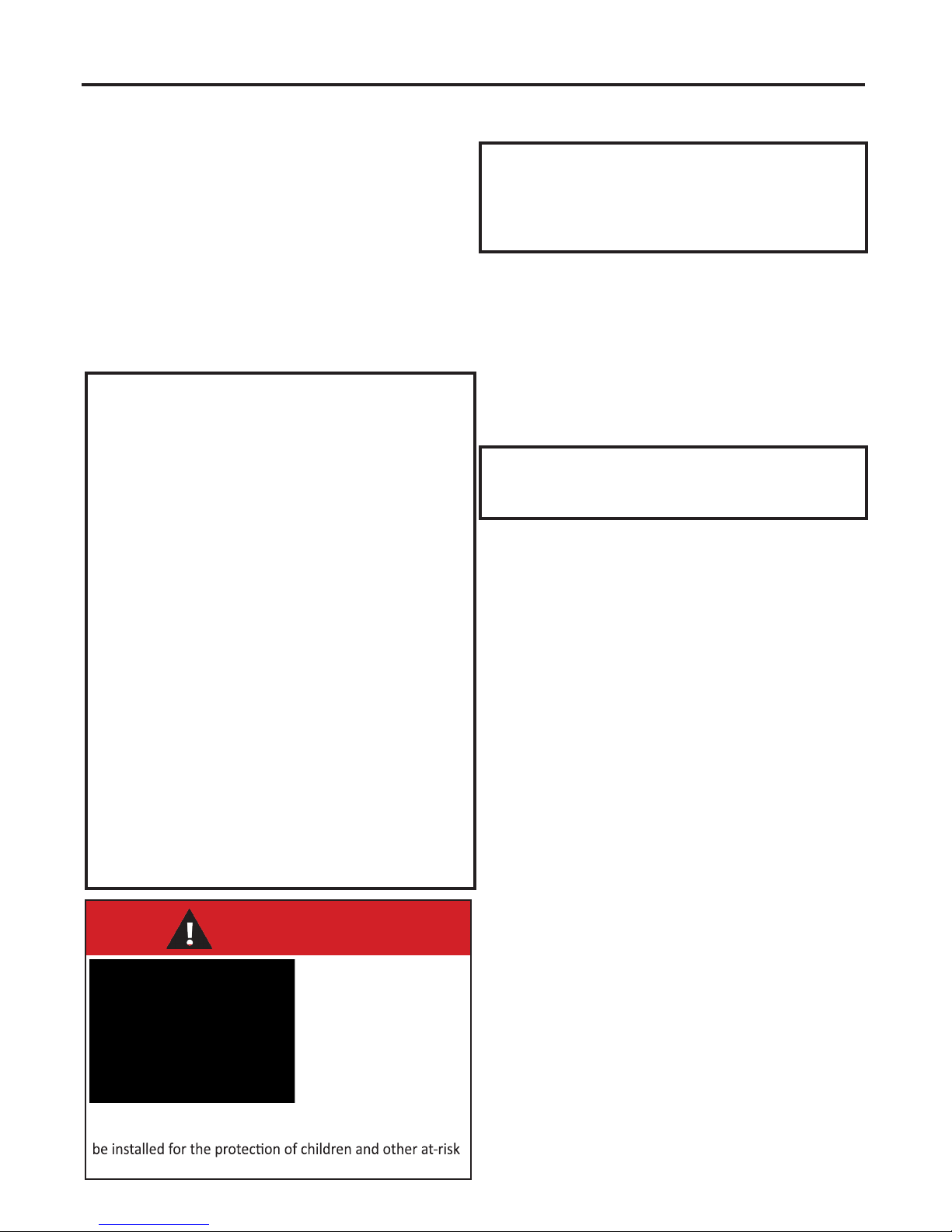
HOT GLASS WILL
CAUSE BURNS
DO NOT TOUCH GLASS
UNTIL COOLED.
NEVER ALLOW CHILDREN
TO TOUCH GLASS.
A barrier designed to reduce the risk of burns from the
hot viewing glass is provided with this appliance and shall
individuals.
FOR SAFE INSTALLATION AND OPERATION OF YOUR “ENVIRO” HEATER,
PLEASE CAREFULLY READ THE FOLLOWING INFORMATION:
• All ENVIRO gas-red appliances must be installed in
accordance with their instructions. Carefully read all the
instructions in this manual rst. Consult the building
authority having jurisdiction to determine the need for a
permit prior to commencing the installation.
• NOTE: Failure to follow these instructions could cause
a malfunction of the replace, which could result in death,
serious bodily injury, and/or property damage.
• Failure to follow these instructions may also void your
re insurance and/or warranty.
GENERAL
• Installation and repair should be done by a qualied
service person. The appliance should be inspected before
the rst use and, at least, annually by a qualied service
person. More frequent cleaning may be required due to
excessive lint from carpeting, bedding material, etc. It
is imperative the control compartments, burners and
circulating air passageways of the appliance be kept
clean.
• Due to high temperatures, the appliance should be
located out of high trafc areas and away from furniture
and draperies.
Children and adults should be alerted to the
hazards of high surface temperatures and should
stay away to avoid burn or clothing ignition.
• Young children should be carefully supervised when in
the same room as the appliance. Toddlers, young children
and others may be susceptible to accidental contact
burns. A physical barrier is required if there is a risk for
individuals in the house. To restrict access to a replace
or stove install an adjustable safety gate to keep toddlers,
young children and other at risk individuals out of the
room and away from hot surfaces. Any safety screen,
guard, or barrier removed for servicing an appliance must
be replaced prior to operating the appliance.
• Clothing or other ammable materials should not be
placed on or near the appliance.
• A barrier designed to reduce the risk of burns from the
hot viewing glass is provided with this appliance and shall
be installed for the protection of children and other at-risk
individuals. If the barrier becomes damaged, the barrier
shall be replaced with the manufacturer’s barrier for this
appliance.
FOR YOUR SAFETY
• Installation and service must be performed by a qualied
installer, service agency or gas supplier.
• This installation must conform to local codes or, in the
absence of local codes, with the National Fuel Gas Code,
ANSI Z223.1/NFPA 54, or the Natural Gas and Propane
Installation Code, CSA B149.1.
• To prevent injury, do not allow anyone who is unfamiliar
with the stove to operate it.
• To prevent injury, if the pilot or pilot and burners
have gone out on their own, open the glass door and
wait 5 minutes to air out before attempting to re-
light the stove.
• Always keep the area around these appliances clear of
combustible material, gasoline and other ammable liquids
and vapours.
• These appliances should not be used as a drying rack for
clothing or for hanging Christmas stockings/decorations.
• Due to the paint curing on the stove, a faint odor and slight
smoking will likely be noticed when the stove is rst used.
Open a window until the smoking stops.
Always connect this gas stove to a vent system and vent to
the outside of the building envelope. Never vent to another
room or inside the building. Make sure the specied vent
pipe is used, properly sized and of adequate height to
provide sufcient draft. Inspect the venting system annually
for blockage and signs of deterioration.
WARNING: Failure to position the parts in accordance
with the diagrams in this booklet, or failure to use only
parts specically approved with this appliance, may result in
property damage or personal injury.
WARNING: Do not operate with the glass front removed,
cracked or broken. Replacement of the glass should be done
by a licensed or qualied service person.
• Never use solid fuels such as wood, paper, cardboard, coal,
or any ammable liquids, etc., in this appliance.
• Do not use this appliance if any part has been under water.
Immediately call a qualied service technician to inspect the
appliance and to replace any part of the control system or
any gas control which has been under water.
• Do not abuse the glass by striking it or slamming the door
shut.
• If the Q2LI unit is pulled out of its installation, and the vent-
air intake system is disconnected for any reason, ensure that
the vent-air intake pipes are reconnected and re-sealed in
accordance to the instructions noted in
- DIrect Vent
InItIal InstallatIon
Page 3
Page 4

Table of Contents
Safety Precautions........................................................................................................2
Table of Contents.........................................................................................................4
Codes And Approvals....................................................................................................5
Specications.............................................................................................................6
Dimensions.....................................................................................................6
Rating Label Location.........................................................................................6
Operating Instructions..................................................................................................7
Lighting and Turning Off Instructions...................................................................7
Air Shutter.........................................................................................................8
Normal Sounds During Operation......................................................................8
Remote Control Operation.................................................................................8
Initializing the System for the First Time............................................................11
Switching to Continuous Pilot..........................................................................11
Fan Control.....................................................................................................13
Maintenance And Service............................................................................................14
Routine Maintenance........................................................................................14
Cleaning The Glass............................................................................................14
Cleaning The Firebox........................................................................................14
Replacing the Glass...........................................................................................14
Cleaning Decorative Surfaces............................................................................15
Glass Door Removal.........................................................................................15
Burner Removal...............................................................................................16
Access Door.....................................................................................................16
Fuel Conversion...............................................................................................17
Conversion Kit Installation.................................................................................18
Initial Installation.......................................................................................................20
Introduction.................................................................................................20
Placement and Framing....................................................................................20
Rear Vent Conversion.......................................................................................21
Corner Installation...........................................................................................22
Framing Plate Installation..................................................................................23
Mantle and Non-Combustible Clearances............................................................24
Direct Vent......................................................................................................25
Vent Termination Restrictions............................................................................26
Venting Clearances..........................................................................................27
Approved Venting Parts.....................................................................................27
Horizontal Termination - Rear Vent....................................................................29
Allowable Co-Axial Vent Congurations..............................................................30
Horizontal Termination.....................................................................................31
Vertical Termination........................................................................................32
Gas Line Connection and Testing.......................................................................35
Electrical Requirements ...................................................................................36
Secondary Installation................................................................................................37
Panel Installation..............................................................................................37
Fire Grate and Log Set Installation.....................................................................38
Trouble Shooting.............................................................................................41
Parts List....................................................................................................................42
Parts Diagram.............................................................................................................43
Notes...................................................................................................................44
Warranty...........................................................................................................46
Installation Data Sheet...............................................................................................47
Page 4
Page 5
Codes And Approvals
DIRECT VENT ONLY: This type is identied by the sufx DV. This appliance draws all of its air for
combustion from outside the dwelling, through a specially designed vent pipe system.
This appliance has been tested and approved for installations from 0 feet to 4500 feet (1372 m) above
sea level.
In the USA: The appliance may be installed at higher altitudes. Please refer to your American Gas
Association guidelines which state: the sea level rated input of Gas Designed Appliances installed at
elevations above 2000 (610 m) feet is to be reduced 4% for each 1000 feet (305 m) above sea level.
Refer also to local authorities or codes which have jurisdiction in your area regarding the de-rate
guidelines.
In Canada: When the appliance is installed at elevations above 4500 feet (1372 m), the certied high
altitude rating shall be reduced at the rate of 4% for each additional 1000 feet (305 m).
• This appliance has been tested by INTERTEK and found to comply with the established VENTED
GAS FIREPLACE HEATER standards in CANADA and the USA as follows:
VENTED GAS FIREPLACE HEATER (Q2LI; NATURAL GAS, PROPANE GAS)
TESTED TO: ANSI Z21.88-2014/CSA 2.33-2014 VENTED GAS FIREPLACE HEATERS
CAN/CGA 2.17-M91 (R2009) GAS FIRED APPLIANCES FOR HIGH ALTITUDES
This ENVIRO Q2LI Fireplace:
• Has been certied for use with either natural gas or propane (see rating label).
• Is not for use with solid fuels.
• Is approved for bedroom or bed sitting room. (IN CANADA: must be installed with a listed wall
thermostat. IN USA: see current ANSI Z223.1 for installation instructions.)
• Must be installed in accordance with local codes. If none exist, use current
installation code CAN/CGA B149 in Canada or ANSI Z223.1/NFPA 54 in the
USA.
• Must be properly connected to an approved venting system and not connected
to a chimney ue serving a separate solid-fuel burning appliance.
IMPORTANT NOTICE (Regarding rst re up): When the unit is turned
on for the rst time, it should be turned onto high without the fan on (if
equipped) for the rst 4 hours. This will cure the paint, logs, gasket material
and other products used in the manufacturing process. It is advisable to
open a window or door, as the unit will start to smoke and can irritate
some people. After the unit has gone through the rst burn, turn the unit
off including the pilot, let the unit get cold then remove the glass door
and clean it with a good gas replace glass cleaner, available at your local
ENVIRO dealer.
Page 5
Page 6
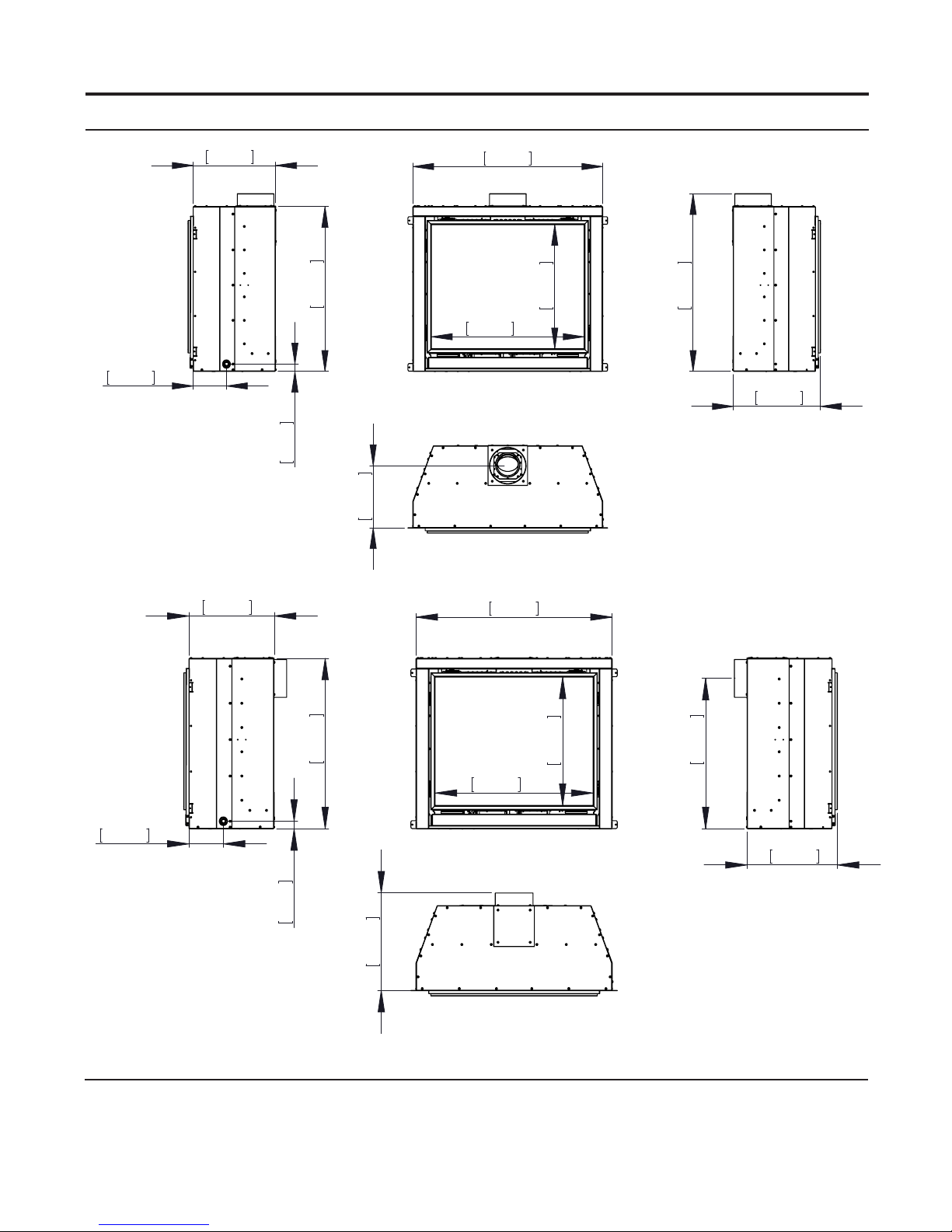
Dimensions:
14 15/16"
380mm
Specications
34 3/8"
874mm
153mm
29 7/8"
759mm
6"
GAS LINE
34mm
1 5/16"
11 1/4"
286mm
VIEWING
AREA
27 11/16"
703mm
22 1/2"
571mm
818mm
32 3/16"
15 13/16"
401mm
Figure 1. Q2LI Dimensions - Top Vent
14 15/16"
380mm
34 3/8"
874mm
VIEWING
AREA
27 11/16"
703mm
22 1/2"
571mm
26 3/8"
669mm
15 13/16"
401mm
153mm
29 7/8"
759mm
6"
GAS LINE
34mm
1 5/16"
434mm
17 1/16"
Figure 2. Q2LI Dimensions - Rear Vent
Rating LabeL & Lighting instRuctions Location:
To access the rating label and lighting instructions ip down the control cover. The plates are attached
to a length of chain and are never to be tampered with or removed. All important information for your
replace is on this label as well of the model specic serial number which you will need for warranty
information.
Page 6
Page 7
Operating Instructions
For Your Safety, Read Safety Precautions And
Lighting Instructions Before Operating
WARNING: IF YOU DO NOT FOLLOW THESE INSTRUCTIONS EXACTLY A FIRE OR EXPLOSION MAY
RESULT, CAUSING PROPERTY DAMAGE, PERSONAL INJURY OF LOSS OF LIFE.
Lighting anD tuRning off instRuctions:
FOR YOUR SAFETY READ BEFORE OPERATING
WARNING:IF YOU DO NOT FOLLOW THESE INSTRUCTIONS EXACTLY, A FIRE OR EXPLOSION
MAY RESULT CAUSING PROPERTY DAMAGE, PERSONAL INJURY OR LOSS OF LIFE.
A. This appliance is equipped with an ignition device
which automatically lights the pilot. Do not try to
light the pilot by hand.
B. BEFORE OPERATING smell all around the
appliance area for gas. Be sure to smell next to the
floor because some gas is heavier than air and will
settle on the floor.
WHAT TO DO IF YOU SMELL GAS:
Do not try to light any appliance.
Do not touch any electrical switch; do not use any
phone in your building.
Immediately call your gas supplier from a
neighbor’s phone. Follow the gas supplier’s
instructions.
If you cannot reach your gas supplier, call the
fire department.
OPERATING INSTRUCTIONS
C. Use only your hand to push in or
turn the gas control knob. Never
use tools. If the knob will not push
in or turn by hand, don’t try to
repair it, call a qualified service
technician. Force or attempted
repair may result in a fire or
explosion.
D. Do not use this appliance if any
part has been under water.
Immediately call a qualified service
technician to inspect the appliance
and to replace any part of the
control system and any gas control
which has been under water.
1. STOP! Read the safety information above on this label.
2. Read the owner's manual including the section on
"Remote Control" operation.
3. Set the thermostat to the lowest setting.
4. Turn off all electric power to the appliance.
5. Do not attempt to light the pilot by hand.
6. Wait five (5) minutes to clear out any gas. Then smell for
gas, including near the floor. If you smell gas, STOP!
Follow "B" in the safety information above on this label.
If you don't smell gas, go to the next step.
7. Turn on all electric power to the appliance.
8. Using the remote control, set
thermostat to desired setting, or
press the ON/OFF key on the
remote. "ON" will be indicated on the
display of the remote and an audible
"beep" will be heard at the unit to
indicate the command has been
received.
9. This appliance is equipped with a
completely automatic ignition and
lighting control. The control will
attempt to light the pilot several
times if necessary. If it is
unsuccessful, it will discontinue
operations. If the appliance will
not operate, follow the
instructions "To Turn Off Gas To
Appliance" and call your service
technician or gas supplier.
Blue LCD Display
ON/OFF Key
THERMOSTAT Key
UP/DOWN Arrow Key
MODE Key
TO TURN OFF GAS TO APPLIANCE
1. Set thermostat to lowest setting, or press the ON/OFF Key. "OFF" will be indicated on the display
and an audible "Beep" will be heard at the unit to indicate the command has been received.
2. Turn off all electric power to the appliance if service is to be performed.
C-12455
Figure 3. Lighting Instruction Label
Page 7
Page 8
Operating Instructions
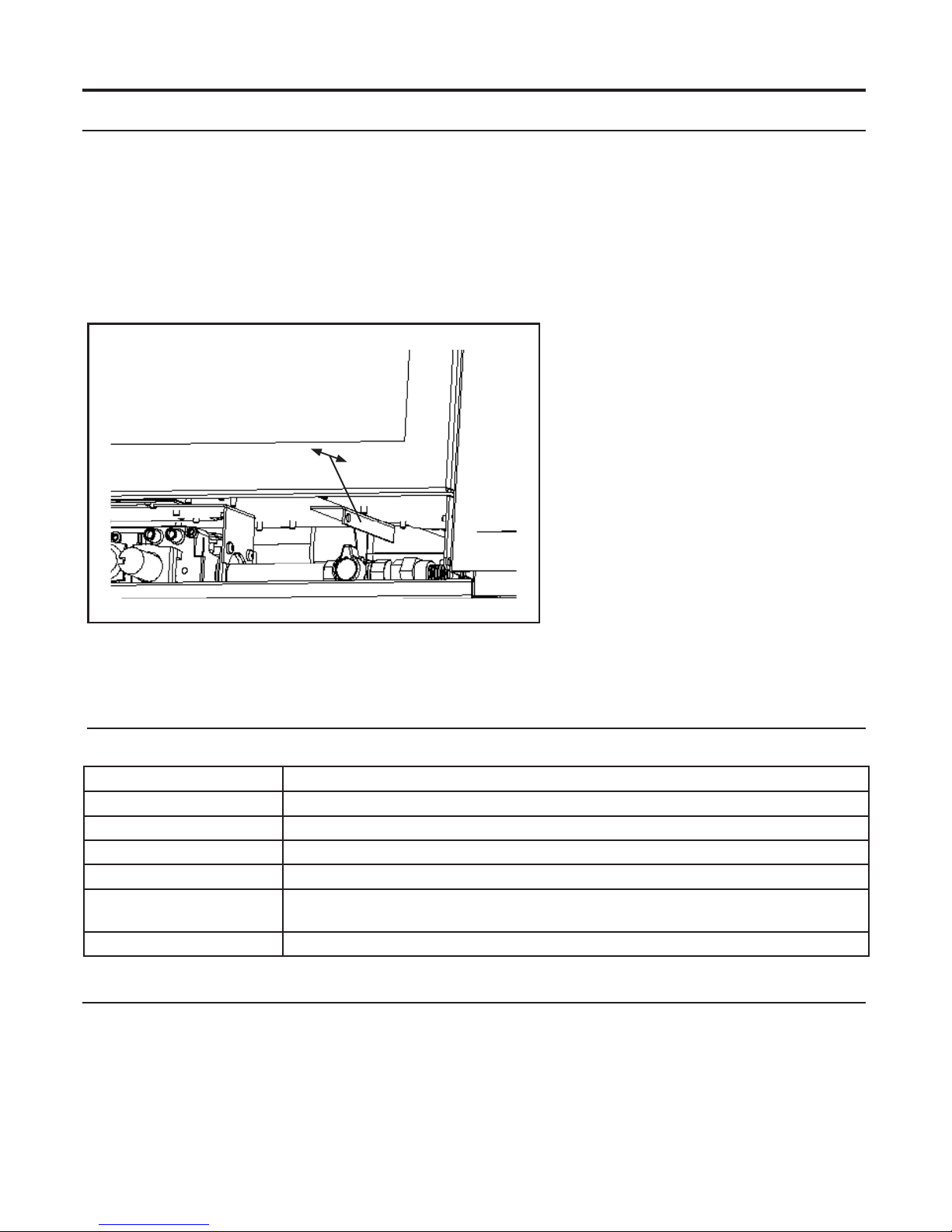
aiR shutteR:
The air shutter adjustment lever is on the right hand side of the control area (see Figure 4).
The air shutter allows the amount of air coming into the replace to be adjusted in order to accommodate
different climates and venting arrangements. Start the pilot and then the burner. Make sure the pilot
ame is burning normally and none of the burner ports are plugged. Let the replace burn for roughly
fteen minutes and make adjustments as necessary.
The ideal ame will be blue at the base and light orange above. The ames should be of medium
height. If the ames look like this, no venturi adjustment is needed. If the ames are fairly short and
mostly blue, the replace is getting too
Note: Use the door tool to adjust
the venturi lever
More Primary Air
Less Primary Air
much air. Therefore, the air shutter
should be closed (pulled out) slightly
until the correct ames are achieved.
Flames that are very orange, with tall,
dark, stringy tips, are not getting enough
air. Open (push in) the venturi until the
ames clean up. If the venturi is opened,
or closed all the way, and the correct
ames cannot be attained, turn off the
gas and contact the dealer.
Warning: Incorrect venturi adjustment
may lead to improper combustion, which
is a safety hazard. Contact the dealer if
there is any concern about the venturi
Figure 4. Air shutter adjustment lever.
adjustment.
noRmaL sounDs DuRing opeRation:
Table 1: Normal Sounds
Component Sound & Reason
Q2LI & Surround Panels Creaking when heating up or cooling down.
Burner Light pop or poof when turned off; this is more common with LP units.
Temperature Sensor Clinking when it senses to turn the blower on or off.
Pilot Flame Quiet whisper while the pilot ame in on.
Blower / Fan Air movement that increase and decreases with the speed of the blower. The
blower is pushing the heat from the replace into the room.
Gas Control Valve Dull click when turning on or off, this is the valve opening and closing.
Remote contRoL opeRations:
The Proame 2 GTMFL is a modular remote control system that directs the functions of the Q2LI.
The Proame 2 GTMFL is congured to control the on/off main burner operation, its ame levels and
provides on/off and Smart thermostatic control of the appliance. The system controls a remotely actuated
120V/60Hz power outlet, and fan speed through six (6) levels.
Page 8
Page 9
Operating Instructions
system DescRiption:
The Proame 2 Remote Control System consists of two (2) elements:
1. Proame 2 Transmitter.
2. Integrated Fireplace Controller (IFC) and a wiring harness to connect the Receiver to the gas valve,
stepper motor and Fan Control Module.
ATTENTION!
- TURN “OFF” THE MAIN GAS SUPPLY OF THE APPLIANCE DURING INSTALLATION OR
MAINTENANCE OF THE RECEIVER.
- TURN “OFF” MAIN GAS SUPPLY TO THE APPLIANCE PRIOR TO REMOVING OR REINSERTING
THE BATTERIES IN THE BATTERY HOLDER
technicaL Data
Transmitter (Remote Control):
Supply voltage: 4.5 V (three 1.5 V AAA batteries)
Radio frequency: 315 MHz
Integrated Fireplace Controller (IFC):
Supply voltage: AC IN - 120 V / 60 Hz
Battery Backup IN - 6 Vdc - 200mA (four 1.5 V AA batteries)
Spark voltage / frequency: >10kV / 1Hz
Comfort modulating fan: 120 V / 60 Hz / 2A
Auxiliary: 120 V / 60 Hz / 5A (not used)
tRansmitteR:
The Proame 2 Transmitter is a remote control with a blue backlit lcd display. It uses a streamline design with
a simple button layout and informative lcd readout (Figure 5). The Transmitter is powered by three (3) AAA
type batteries. A Mode Key is provided to Index between the features and a Thermostat Key is used to turn
on/off or index through Thermostat functions (Figure 5 & 6)
Figure 5: Proame 2 Transmitter.
Page 9
Page 10
CPI Mode
Operating Instructions
Figure 6: Proame 2 Transmitter LCD Screen.
integRateD fiRepLace contRoLLeR (ifc):
The Proame 2 IFC (Figure 7) connects directly to the gas valve, stepper motor, pilot and covection fan with a wiring
harness. The IFC is mainly powered by 120 VAC but can also run off a battery backup four (4) AA type batteries for
shorter periods of time. The IFC accepts commands via radio frequency from the Transmitter to operate the appliance
in accordance with the particular Proame 2 system conguration. The IFC has a red reset button at the front right
corner that is used is to synchronize the Transmitter when using the for the rst time, or after the batteries have been
replaced.
Page 10
Reset Button
Figure 7: Integrated Fireplace Controller
Page 11
Operating Instructions
opeRating pRoceDuRe:
Initializing The System For The First Time
Install the four (4) AA batteries into the IFC battery holder. Note the polarity of the battery and insert into the battery
bay as indicated on the body of the battery holder. Press the reset button on the IFC marked “SW1” (see Figure 7).
The IFC will “beep” three (3) times to indicate that it is ready to synchronize with a Transmitter. Install the three (3)
AAA type batteries in the Transmitter battery bay, located on the base of the Transmitter. With the batteries already
installed in the Transmitter, push the ‘ON’ button. The IFC will “beep” four (4) times to indicate the Transmitter’s
command is accepted and sets to the particular code of that Transmitter. The system is now initialized.
Temperature Indication Display
With the system in the “OFF” position, press the
Thermostat Key and the Mode Key at the same time.
Look at the LCD screen on the transmitter to verify that
a °C or °F is visible to the right of the Room Temperature
display (see Figure 8).
Turn on the Appliance
Press the ON/OFF Key on the Transmitter. The
Transmitter display will show all active Icons on the
screen. A single “beep” from the Receiver will conrm
reception of the command and will commence to rst
ignite the pilot light, followed by the main burner. This should take about 10 seconds to complete.
Figure 8: Remote Control Display in Farenheit and Celcius.
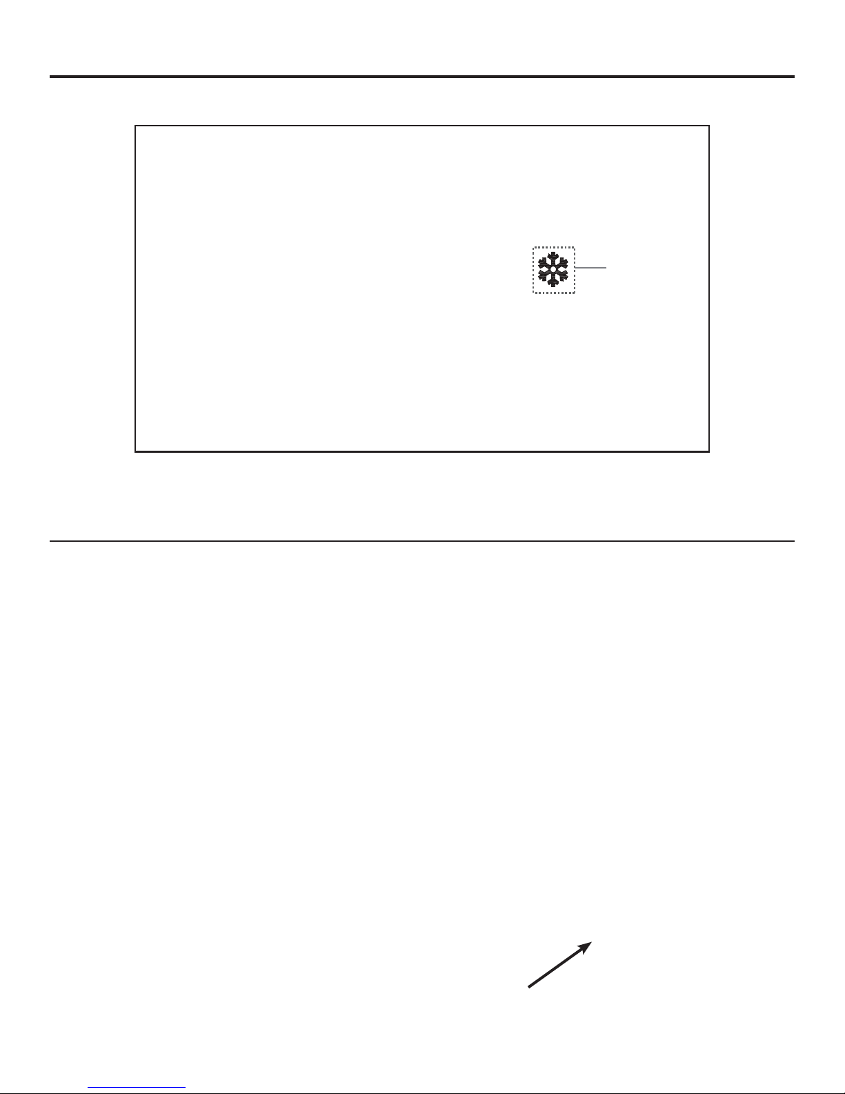
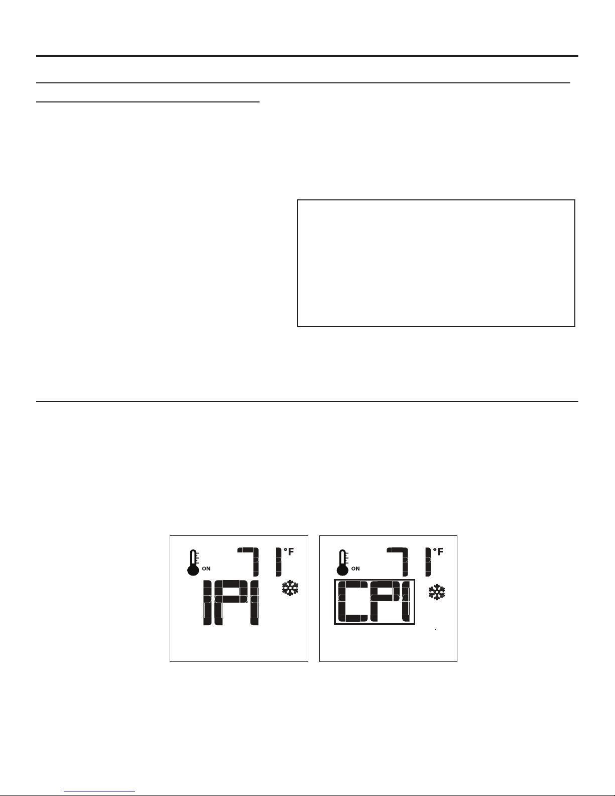
switching to continuous piLot moDe:
When the Q2LI is turned off press the mode key to index to the constant pilot (CPI) mode icon (see gure 9).
Pressing the up arrow key will select Continuous Pilot Ignition (CPI) and pressing the down arrow key will return
to IPI. Once a selection is made the IFC will beep once to conrm it had received the command. NOTE: It is
recommended to use the continuous pilot mode during the winter when the outside temperature
is below 50°F (10°C) to keep the chimney properly heated for updraft during burner ignition.
Continuous pilot mode also keeps the rebox warm which eliminates both heat loss to cold air that is trapped
inside the rebox as well as excessive exhaust vapour condensation on the door glass.
Figure 9: CPI Pilot Mode.
Page 11
Page 12
Room Temperature
Set Temperature
Thermostat ON
Flame Off
Flame Level 1
Flame Level 5
Maximum Flame Level
Operating Instructions
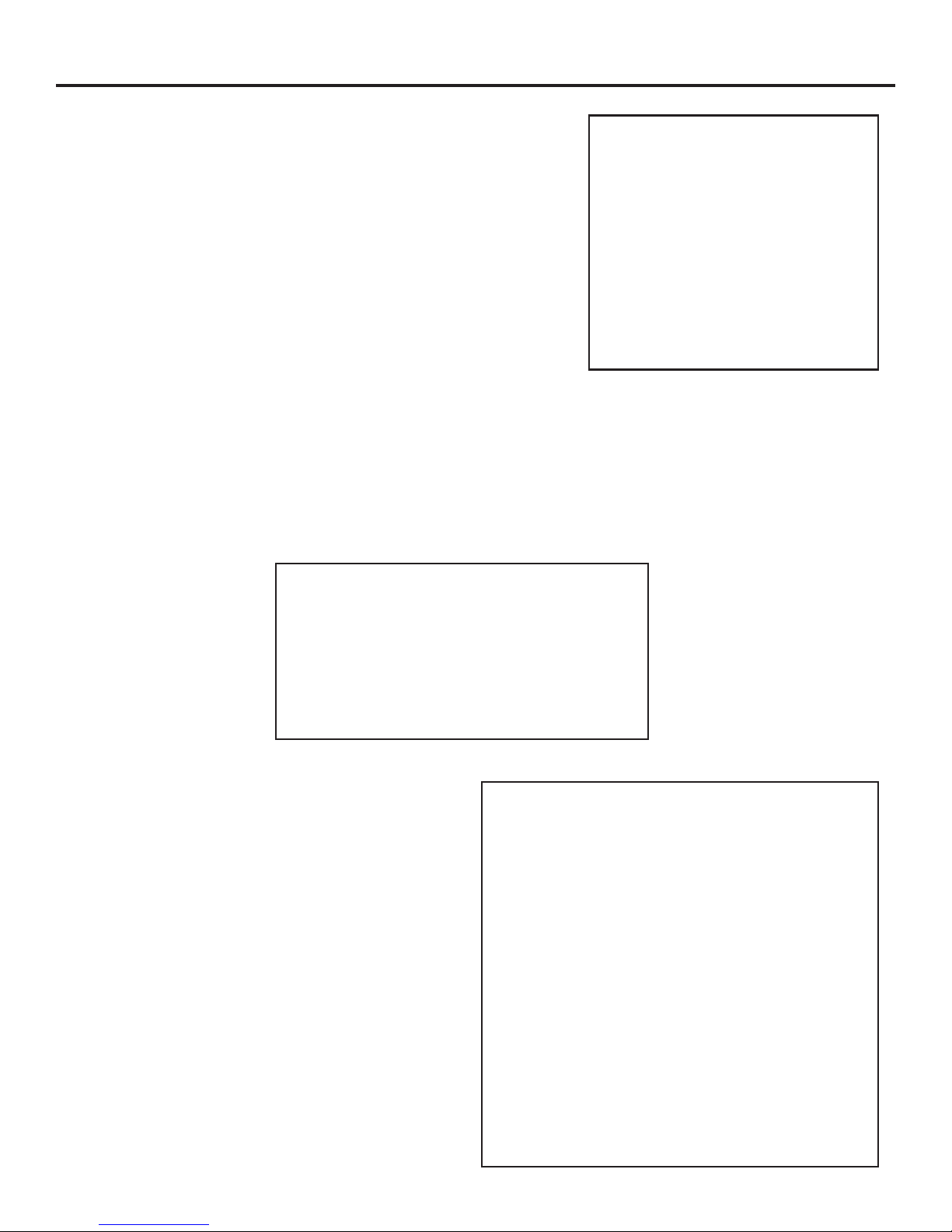
Turn off the Appliance
Press the ON/OFF Key on the Transmitter. The Transmitter LCD display
will only show the room temperature and Icon (see Figure 10). A single
“beep” from the IFC conrms reception of the command and both the
pilot light (if the unit is not set to continuous pilot) and main burner will
turn off.
Room Thermostat (Transmitter Operation)
The Remote Control can operate as a room thermostat. The thermostat
can be set to a desired temperature to control the comfort level in a
room. To activate this function, press the Thermostat Key (see Figure
5). The LCD display on the Transmitter will change to show that the
room thermostat is “ON” and the set temperature is now displayed (see
Figure 10). To adjust the set temperature, press the Up or Down Arrow
Keys until the desired set temperature is displayed on the LCD screen
of the Transmitter.
Smart Thermostat (Transmitter Operation)
The Smart Thermostat function adjusts the ame height in accordance to the difference between the set
point temperature and the actual room temperatures. As the room temperature gets closer to the set point
the Smart Function will modulate the ame down. To activate this function, press the Thermostat Key (Figure
5) until the word “SMART” appears to the right of the temperature bulb graphic (Figure 11). To adjust the
set temperature, press the Up or Down Arrow Keys until the desired set temperature is displayed on the LCD
screen of the Transmitter.
Figure 10: Remote Control Displays
Set Temperature.
Figure 11: Remote Control’s Smart Flame Function.
Remote Flame Control
The Proame 2 GTMF has six (6) ame levels. With the
system on, and the ame level at the maximum in the
appliance, pressing the Down Arrow Key once will reduce
the ame height by one step until the ame is turned
off. The Up Arrow Key will increase the ame height
each time it is pressed. If the Up Arrow Key is pressed
while the system is on but the ame is off, the ame will
come on in the high position (refer to Figure 12). A single
“beep” will conrm reception of the command.
Page 12
Figure 12: Remote Control’s Flame Levels.
Page 13
Operating Instructions
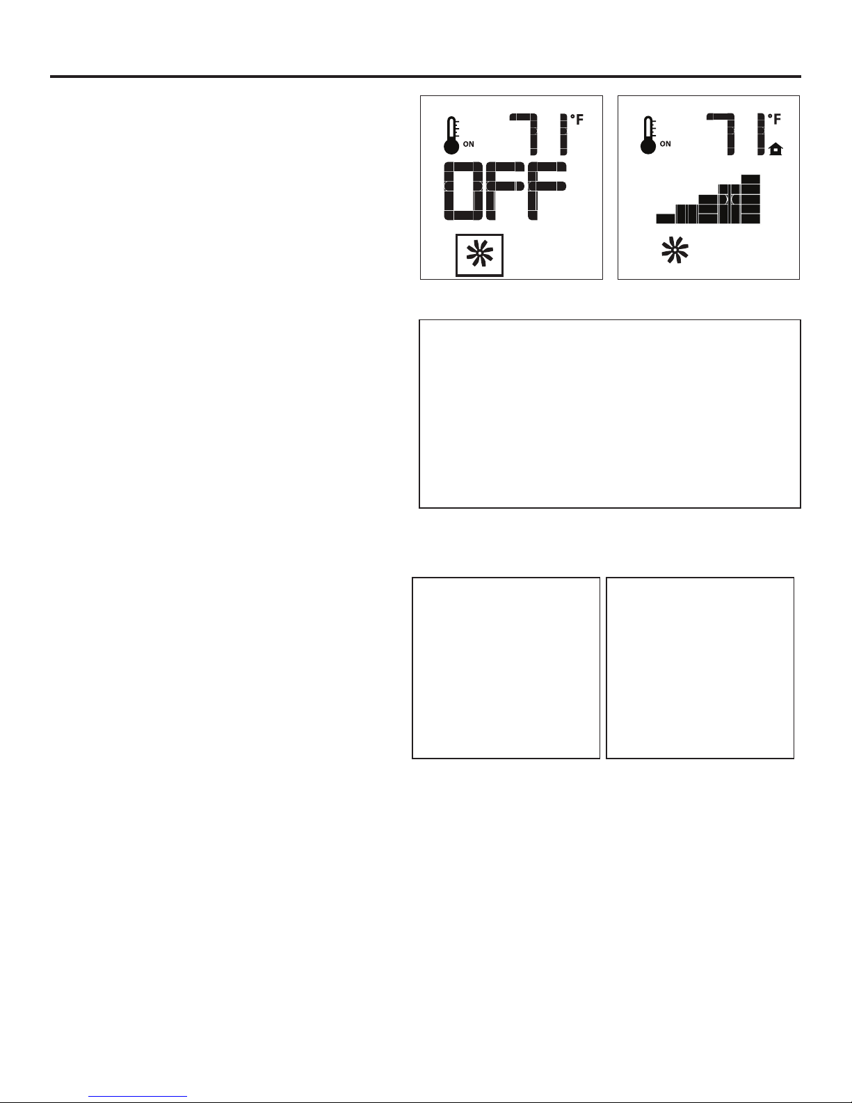
Fan Control
The Q2LI comes with a convection fan that can be
controlled with the Transmitter. The fan speed can be
adjusted thorugh six (6) speeds. To control the fan
press the MODE key (Figure 5) to index to the fan
control icon (Figure 13). Use the UP/DOWN arrow keys
to turn on, off, or adjust the fan speed (Figure 13). A
single beep from the IFC will conrm the command
has been received
Key lock
This function will lock the keys to avoid unsupervised
operation. To activate this function, press the MODE
and UP keys at the same time and the a lock will
appear (see Figure 15). To de-activate this function,
press the MODE and UP Keys at the same time.
Low Battery Power Detection
Transmitter: The life span of the remote control
batteries depends on various factors: quality of
the batteries used, the number of ignitions of
the appliance, the number of changes to the
room thermostat set point, etc. When the
Transmitter batteries are low, a Battery Icon will
appear on the LCD display of the Transmitter
(see Figure 16) before all battery power is lost.
When the batteries are replaced this Icon will
disappear.
IFC: The life span of the IFC batteries depends on
various factors during a prolonged power outage:
quality of the batteries used, the number of ignitions
of the appliance, the number of changes to the room
thermostat set point etc. When the IFC batteries are
low, No “beep” will be emitted when it receives an
On/Off command from the Transmitter. This is an
alert for a low battery condition for the IFC. When the
batteries are replaced the “beep” will be emitted from
the Receiver when the ON/OFF Key is pressed (See
InItIalIzIng the system for the fIrst tIme).
Figure 13: Fan Control
Figure 14: Remote Control with Aux (not used)
Figure 15: Remote Control
Locked.
Figure 16: Low Battery
Indicator.
WARNING: Fire Hazard. Can cause severe injury or death The Receiver causes ignition of the appliance.
The appliance can turn on suddenly. Keep away from the appliance burner when operating the remote
system or activating manual by pass of the remote system.
WARNING: Shock Hazard. Can cause severe injury or death. This device is powered by line voltage. Do
not try to repair this device. In no way is the enclosure to be tampered with or opened. Disconnect from
line voltage before performing any maintenance.
WARNING: Devices rated more than 5A shall not be connected to the OUT receptacle. Devices rated
more than 1A shall not be connected to the FAN receptacle. Devices rated more than 2A shall not be
connected to the AUX receptacle.
CAUTION: Property Damage Hazard. Excessive heat can cause property damage. The appliance can stay
lit for many hours. Turn off the appliance if it is not going to be attended for any length of time. Always
place the Transmitter where children cannot reach it.
Page 13
Page 14

Maintenance And Service
Routine maintenance:
At least once a year, run through the following procedures to ensure the system is clean and working
properly. Check the burner to see if all the ports are clear and clean. Check the pilot to make sure it is not
blocked by anything. The pilot ame should be blue with little or no yellow on the tips.
WARNING: Clearances must be sufcient to allow access for maintenance and service
WARNING: Failure to position the parts in accordance with this manual, or failure to use only parts
specically approved with this appliance may result in property damage or personal injury.
The venting system must be periodically examined; it is recommended the examination is done by a
qualied agency.
cLeaning the gLass:
When the replace has cooled, remove the face of the replace along with the glass. See maIntenance
anD serVIce - glass Door remoVal. Check the gasket material on the back of the glass, making sure that
it is attached and intact.
During a cold start up, condensation will sometimes form on the glass. This is a normal condition with all
replaces. However, this condensation can allow dust and lint to cling to the glass surface. Initial paint
curing of the appliance can leave a slight lm behind the glass, a temporary problem. The glass will need
cleaning about two weeks after installation. Use a mild glass cleaner and a soft cloth. Abrasive
cleaners will damage the glass and painted surfaces. Depending on the amount of use, the glass
should require cleaning no more than two or three times a season. Do not clean the glass when it is
hot.
cLeaning the fiRebox:
Remove the logs carefully, as they are very fragile. Gently remove all the coals and place on a paper
towel. Vacuum the bottom of the rebox thoroughly. Carefully clean any dust off the logs and remove
any lint from the burner and pilot. At this time, inspect the burner tube for cracking or severe warping.
If a problem is suspected, contact the dealer. Check the logs for deterioration or large amounts of soot;
a small amount on the bottom side of the logs is normal. Replace the logs and coals as in the seconDary
InstallatIon - fIre grate anD log set InstallatIon section. If new/more coals are required, contact your
nearest ENVIRO dealer.
RepLacing the gLass:
The glass in the replace is a high temperature ceramic. If the glass is damaged in any way, a factory
replacement is required (see Parts lIst). Wear gloves when handling damaged glass door assembly
to prevent personal injury. Do not operate with the glass front removed, cracked or broken. Removal
and replacement of the glass from the door must be done by a licensed or qualied service person.
The glass must be purchased from an ENVIRO dealer. No substitute materials are allowed.
Remove the door (see page 15). The replacement glass will come with a new gasket installed. Remove
any silicone remnants from the door. Apply high temperature silicone to the two vertical faces of the
door and install the new piece of glass with gasket (be sure to maintain edge clearances). Apply even
pressure to the glass to allow the silicone to adhere to the gasket material.
Page 14
Page 15
Maintenance And Service
cLeaning DecoRative suRfaces:
Painted and porcelain faces should be wiped with a damp cloth periodically. If a plated face has been
purchased, it should be unpacked/unwrapped carefully to avoid getting anything on the surface of the
nish, including cleaners, polish and nger prints. It is important to note that ngerprints and other
marks can leave a permanent stain on plated nishes. To avoid this, give the face a quick wipe with
denatured alcohol on a soft cloth BEFORE lighting the replace. Never clean the face when it is
hot. Do not use other cleaners as they may leave a residue, which can become permanently etched into
the surface.
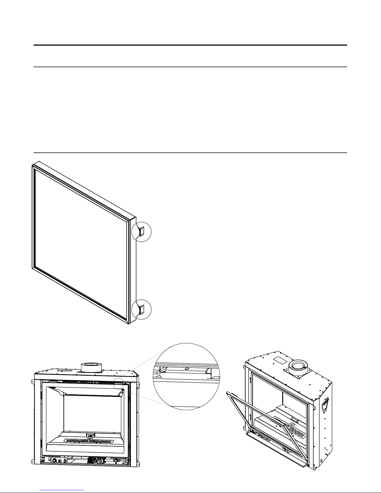
gLass DooR RemovaL: (Q2g unit shown)
The door needs to be removed for
sceduled cleaning and to install the glass
media and other options.
First remove the safety screen by
grabbing the top and bottom of the frame
and lifting it up and out. To remove the
glass door use your two index ngers to
pull the spring latches up over the two
door tabs. Once release pivot the door
to out and pull it out of the bottom door
retainers. The door must be angled in
Figure 17.
Safety Screen
Mounts
order for it to pull out.
To replace the glass door, simply reverse
the above procedure.
WARNING: Do not touch or attempt to
remove the glass door if the replace is
not completely cold.
WARNING: Never operate the replace
with the glass door removed.
Figure 18A. Upper Door Latch
Figure 18B. Bottom Door Retainers
Page 15
Page 16

Maintenance And Service
buRneR RemovaL:
The burner may need to be removed for a few reasons, including cleaning under the burner or to be
replaced all together. Proceed only when the unit has completely cooled down.
Step 1: Remove the glass door as shown in
the maIntenance anD serVIce - glass Door
remoVal.
Step 2: Remove the log set and re grate
as shown in SeconDary InstallatIon - fIre
grate anD log set InstallaIon
Step 3: Pull the burner out of the venturi box
and out.
To re-install the burner follow steps 1-3
in reverse. When placing the burner back
in the unit be sure not to move the air
shutter. Insure the front and rear lengths
of the burner tube are parallel as it may
have distorted with heat over time. The
ideal placement for the burner tube
is keeping it forward up against the
burner stand stops.
Figure 19. Removing Burner
access DooR:
There is an access door in the bottom on the rebox that is used for servicing components after the unit
is installed in a construction enclosure. Proceed only when the unit has completely cooled down.
Step 1: Remove the burner as shown in
the maIntenance anD serVIce - Burner
remoVal.
Step 2: Remove the Upper Air Diverter by
removing (2) T-20 bolts. Remove the
Lower Air Diverter.
Step 3: Remove the right and left burner
stands by removing (4) T-20 bolts.
Step 4: Remove the (16) T-20 bolts
retaining the access door as shown in
Figure 20.
Step 5: After serviving assemble in the
reverse order and be sure the gasket is
still intact. Replace if necessary.
Figure 20. Removing Access Door
Page 16
Page 17

Maintenance And Service
fueL conveRsion:
TO BE INSTALLED BY A QUALIFIED SERVICE AGENCY ONLY
Please read and understand these instructions before installing.
Warning: This conversion kit shall be installed by a qualied service agency in accordance
with the manufacturer’s instructions and all applicable codes and requirements of the
authority having jurisdiction. If the information in these instructions is not followed
exactly, a re, explosion or production of carbon monoxide may result causing property
damage, personal injury or loss of life. The qualied service agency is responsible for
the proper installation of this kit. The installation is not proper or complete until the
operation of the converted appliance is checked as specied in the manufacturer’s
instructions supplied with the kit.
Kit Parts List for all Q2 IPI Models:
1 - Orice (NG - #40 DMS or LP - #55 DMS) as marked
1 - Stepper Regulator with Diaphragm
1 - Installation instruction sheet
1 - Conversion label
Carefully inspect all parts supplied with this conversion kit. If any parts have been damaged or are
missing, contact your dealer, distributor or courier company to have them replaced before starting this
installation.
Page 17
Page 18

Maintenance And Service
Conversion Kit Installation:
1. Turn the unit off by pressing the ON/OFF Key on the remote and shut off gas supply at the shut-off
valve upstream of the unit. CAUTION: The gas supply must be shut off prior to disconnecting the
electrical power and before proceeding with the conversion. Allow the valve and unit to cool down
to room temperature.
2. Remove the glass door as shown in the maIntenance anD serVIce - glass Door remoVal.
3. Carefully remove the log set and re grate.
4. Remove the burner as shown in the maIntenance anD serVIce - Burner remoVal.
5. Convert the pilot injector (see Figure 21):
a) Using a
1
/4 turn counter-clockwise
b) Push the slider with your nger or
at head screwdriver
- Natural Gas is marked NAT.
- Propane gas is marked LP with an
indicating hole between L and P.
It is also marked red.
7
/16” wrench, turn the pilot head a
c) Turn the pilot head a 1/4 turn clockwise
back to its original position.
6. Convert the burner orice:
a) Remove the main burner orice with a
1
/2” deep socket
Figure 21. Pilot Slider set to LP
b) Replace the NG orice with the LP orice. Do not over-tighten. The LP orice hole will always be
smaller then the NG hole.
7. Convert the SIT gas valve:
a) Use a T-20 driver to remove the two screws that hold the stepper regulator to the gas valve and
disconnect the wire harness from the IFC.
b) Remove the rubber regulator diaphragm that is situated between the stepper regulator and the valve
body. The new stepper regulator already has this diaphragm installed.
c) Install the LP stepper regulator, with the new longer T-20 screws included in the kit and connect the
harness to the IFC.
8. Reinstall the burner, re grate, log set, and glass door. Also refer to seconDary InstallatIon - fIre
grate anD log set InstallatIon in your Owner’s Manual. When re-installing the burner, ensure that
the burner to pilot hood and shield relationship is similar to what is shown in Figure 22.
9. Reconnect the main gas line if it was disconnected and open the shut-off valve at the gas line to the
unit.
10. Reconnect the electrical power to the unit.
11. Use a small brush to apply a warm soapy water solution to all gas connections (use a half dish soap
and half warm water). If a gas leak is present, bubbling will occur. Gas leaks can be repaired by
using an approved pipe thread sealant or approved Teon tape. NEVER USE AN OPEN FLAME WHEN
TESTING FOR LEAKS.
12. Relight the pilot and conrm the ame properly covers the ame sensor (see Figure 22). Should the
Page 18
Page 19

Maintenance And Service
13. Relight the main burner in both the “HI” and “LO” positions to verify proper burner ignition, operation
and proper ame appearance. Conrm the inlet and manifold pressures are within the acceptable
ranges as directed in section IntIal IntallatIon - gas lIne connectIon anD testIng. If the Q2LI has
been installed at an altitude higher than 2000ft (610m) it is required to de-rate the unit accordingly:
In the USA: The appliance may be installed at higher altitudes. Please refer to your American Gas
Association guidelines which state: the sea level rated input of Gas Designed Appliances installed at
elevations above 2000 (610 m) feet is to be reduced 4% for each 1000 feet (305 m) above sea level.
Refer also to local authorities or codes which have jurisdiction in your area regarding the de-rate
guidelines.
In Canada: When the appliance is installed at elevations above 4500 feet (1372 m), the certied high
altitude rating shall be reduced at the rate of 4% for each additional 1000 feet (305 m).
14. MAKE SURE that the conversion label is installed on or close to the rating label to signify that the
unit has been converted to a different fuel type.
Figure 22. Correct Burner & Pilot Shield Placement
(Q1I Shown but similar to Q2I)
Page 19
Page 20

Initial Installation
37 7/8"
(962mm)
36¼"
(921mm)
3 5/8"
(93mm)
13
1
/4"
(337mm)
5 5/8"
(143mm)
Gas
Inlet
A
d
j
ac
e
n
t
w
a
l
l
1" min
(25mm)
QUALIFIED INSTALLERS ONLY
intRoDuction:
This section of the owner’s manual is for the use of qualied technicians only. Fireplace placement,
hearths, facing, mantels, and venting terminations will be covered, as well as the gas and electric
systems. There are several installation safety guidelines that must be adhered to. Please carefully read
the safety precautions at the front of this manual.
NOTE: The Q2LI comes as a top vent unit but can be converted to a rear vent.
Warning: Clearances must be sufcient to allow access for maintenance and service.
pLacement anD fRaming:
Table 2. Framing Dimensions.
Firebox Framing
7/8
Depth 15
Width 34
Height - Rear Vent 40” 1016mm
Height - Top Vent *48” 1219mm
Gas Inlet (Distance
From Front)
Gas Inlet (Height) 1
*Just a 90 degree elbow
” 403mm
9/16
” 878mm
6” 152mm
9/16
” 40mm
The location for the replace can be
along a wall, raised, at oor level, or
in a corner. There are specic framing
measurements for each situation.
The basic opening should have the
6”
(152mm)
34 9/16”
(878mm)
dimensions shown in Figure 23.
The replace must have a strong and
level surface to be placed on. The
40”
(1016mm)
14”
7/8
15
”
(356mm)
(403mm)
1 9/16”
(40mm)
surface should be made of wood or a
non-combustible material, not carpet.
The gas line, 3/8” JIC tting, should
be brought to the right side of the
replace. The location should be
chosen so the replace will be at least
Figure 23. Dimensions for Framing the Firebox
36 inches (91.4 cm) from drapes, doors and other combustibles. The framed opening should also
be a minimum of 4 5/8” (11.7 cm) from the nearest perpendicular wall (sidewall to the edge of the
opening).
Page 20
Page 21

Initial Installation
QUALIFIED INSTALLERS ONLY
ReaR vent conveRsion:
For smaller openings the Q2LI can be converted from a top vent to a rear vent unit.
DV Adaptor
Must use 1/4” 8-32
Bolts to secure Cover
Plate and DV Adaptor
Figure 24. Vent Conversion - Step 1
Step 2: Switch the removed parts
around as shown in Figure 26 and
re-install all 12 screws. Be sure not
to damage any gaskets - If damage
occurs fully remove the gasket
and use high temp silicone as a
replacement.
Exhaust Tube
Cover Plate
Must use 1/4” 8-32
Bolts to secure Cover
Plate and DV Adaptor
Figure 24A. Upper Mounting Holes
Step 1: Using a T-20 screwdriver
remove the DV Adaptor, Exhaust
Tube, and cover plate (12 screws
total) as shown in Figure 24.
Note: The DV adaptor and Cover
Plate use the T20 1/4” bolts.
Use lower set of
holes
Figure 25. Lower Mounting Holes
Figure 26. Vent Conversion - Step 2
Page 21
Page 22

Initial Installation
QUALIFIED INSTALLERS ONLY
coRneR instaLLation:
The dimensions for installing a replace in the corner of a room are given in Figures 27A and 27B. Refer
to “InItIal InstallatIon - allowaBle co-axIal Vent confIguratIons” for allowable pipe lengths.
WARNING: Do not interfere with the structural integrity of the walls.
3
7
"
188mm
8
3
42
"
1072mm
16
15"
380mm
7
29
"
758mm
8
9
12
"
319mm
16
9
34
"
878mm
16
Figure 27A. Dimensions for a corner installation
1
13
"
334mm
8
3
42
"
1072mm
16
15"
380mm
7
29
"
758mm
8
9
12
"
319mm
16
Page 22
9
34
"
878mm
16
Figure 27B. Dimensions for a corner installation
Page 23

Initial Installation
QUALIFIED INSTALLERS ONLY
fRaming pLate instaLLation:
A steel framing plate is included with your Q2LI. The plate does not come installed on the unit but it
attaches very easily with a 1/4” hex driver as shown below. This plate is used as a supportive surface to
ll in the air gap above the unit in the installation construction. Non combustible material can be placed
over this plate such a cement board. Non combustible material is only necessary over the replace
opening and does not need to span the entire width of the framing plate. A wood mantle can we placed
over top of the non-combustible as long as it stays within the mantle specicifactions.
Remove these two existing
machine screws from the top of the
cabinet. Place the metal framing
plate on top of the unit and
replace these screws in the same
hole they were removed from.
Steel framing plate
Use this nailing flange set if you
need to create a second layer
of facing material such as tile
or stone. Bend out the flange by
by hand in order to use.
Figure 28A. Framing Plate Installation
Page 23
Page 24

Initial Installation
QUALIFIED INSTALLERS ONLY
mantLe & non-combustibLe cLeaRances:
When installing the Q2LI as a zero clearance replace the correct clearances and materials must be used:
above unit: A minimum 10” of non-combustible facing material must be used above the rebox opening
(in front of the included steel framing plate). The non-combustible is only required directly over the
rebox opening and does not need to span the entire width of the framing plate.
in fRont of unit: The Q2LI can be placed on the oor if desired although it is recommended that it be
raised aleast an inch or higher for more heat sensetive materials such as carpet or linoleum.
aDjacent/siDewaLL: There must be a minimum distance of 4 5/8” (117mm) from the side of the
Q2LI cabinet to an adjacent wall composed of combustible material.
mantLe: It is not necessary to install a mantle, but if one is desired the guidelines as shown in Figure 29.
Page 24
Figure 28B. Non-Combustible Zone
Page 25

Initial Installation
49”
48”
47”
46”
45”
44”
43”
42”
1 2 3 4 5 6 7 8 9 10 11 12
M A N T L E H E I G H T
M A N T L E D E P T H
Minimum Mantle Clearances
12” MANTLE
2” MANTLE
QUALIFIED INSTALLERS ONLY
Figure 29. Mantle Clearances
Note: Mantle height dimensions are based from the bottom of the appliance.
DiRect vent:
WARNING: This appliance has been designed to draw room air for proper heat circulation
from the bottom of the unit, and out the top front. Blocking or modifying these openings in
any way can create hazardous situations.
The vent length for the Q2LI must be between 6” (150 mm) and 40’ (12.2 m). This model is vented
with co-axial 4” intake, 6 5/8” exhaust aluminum or stainless steel approved rigid vent leading into a
vertical or horizontal termination cap. This model can also be used with aluminum or stainless steel ex
venting. The ue collar of this model will t inside of a standard 4” x 6 5/8” vent and must be either
correctly interlocked or fastened, with three screws directly to the vent collar.
Check periodically that the vents are unrestricted. Also ensure that all direct vent pipes have been
properly sealed and installed after routine inspection or cleaning. The air intake and exhaust pipes must
be installed in the correct locations on the top of the Q2LI.
Page 25
Page 26

Initial Installation
vent teRmination RestRictions:
QUALIFIED INSTALLERS ONLY
N
O
D
E
C
B
L
F
Fixed
Closed
Openable
B
B
Openable
Fixed
Closed
H
G
G
M
B
A
J
I
Termination Cap
Figure 30. Vent Termination Restrictions, refer to Table 3
Letter Canadian Installation
A 12 in (30 cm) Clearance above grade, verandah, porch, deck, or balcony.
B 12 in (30 cm) 9 in (23 cm) Clearance from window or door that may be opened.
C 12 in (30 cm)* Clearance from permanently closed window (to prevent
D 24 in (60 cm)* Vertical clearance to ventilated soft located above the
E 18 in (45 cm)* Clearance to unventilated soft.
F 12 in (30 cm)* Clearance to outside corner.
G 12 in (30 cm)* Clearance to inside corner.
H 3 ft (91 cm) within a height of
15 ft (4.5 m) above the meter/
regulator assembly
I 3 ft (91 cm) 3 ft (91 cm)* Radial clearance around service regulator vent outlet.
J 12 in (30 cm) 9 in (23 cm) Clearance to non-mechanical air supply inlet to building, or
K 6 ft (1.83 m) 3 ft (91 cm) above if within 10
L 7 ft (2.13 m
M 12 in / 30 cm
N 12 in (30 cm)* Clearance horizontally to any surface (such as an exterior
O 12 in (30 cm) Clearance above roof line for vertical terminations.
1
)t
+
Air Supply Inlet
Gas MeterG
Restriction Zone
(Termination not allowed)
Table 3: Vent Termination Clearances
US Installation
3 ft (91 cm) within a height of
15 ft (4.5 m) above the meter/
regulator assembly*
ft (3 m) horizontally
7 ft (2.13 m)
12 in / 30 cm*
2
condensation).
terminal, within a horizontal distance of 2 ft (60 cm) from
center line of terminal.
Clearance to each side of center line extended above
meter/regulator assembly.
the combustion air inlet to any other appliance.
Clearance to mechanical air supply inlet.
*t
+
Clearance above paved sidewalk or paved driveway located
on public property.
Clearance under verandah, porch, deck, or balcony.
wall) for vertical terminations.
Description
K
A
1
In accordance with the current CSA B149, Natural Gas and Propane Installation Code.
2
In accordance with the current ANSI Z223.1 NFPA 54, National Fuel Gas Code.
* These numbers are only estimates.
t
A vent shall not terminate directly above a side walk or paved driveway that is located between two single family dwellings and
it serves both dwellings.
+
Permitted only if verandah, porch, deck, or balcony is fully open on a minimum of two sides beneath the oor.
Clearances are in accordance with local installation codes and the requirements of the gas supplier.
NOTE: Venting terminals shall not be recessed into walls or siding.
Page 26
Page 27

Initial Installation
Framing
Joists/Studs
10”
10”
QUALIFIED INSTALLERS ONLY
venting cLeaRances:
A 1” (25 mm) clearance to combustibles must be maintained around any vertical vent pipe. Around a
horizontal vent pipe, the clearance to combustibles should be 2” (51 mm) above and 1½” (38 mm)
on the sides and bottom. When combustible materials are directly above a 90° elbow, 3” (76 mm) of
clearance are necessary.
Table 4. Vent Pipe Minimum Clearances
Vertical Pipe to
the Side Walls
Hard
Pipe
1”
(25.4 mm)
A 10” (254 mm) x 10” (254 mm) frame (see Figure 31) will assure the proper support and spacing for
the vent pipe as it passes through the wall. Installations in Canada require that a wall thimble be used for
passing through walls and ceilings. All sealing and vapour barriers must comply with local building codes.
The conguration of the venting pipes depends on the locations
of walls, ceilings, and studs. However, the pipes cannot be of
arbitrary length and arrangement. Because the length of the
vertical and horizontal sections dramatically affects the burning
efciency of the replace, certain guidelines have been set in
InItIal InstallatIon - allowaBle co-axIal Vent confIguratIons.
Venting terminals can not be recessed into a wall or siding.
Horizontal Pipe to
the Sides & Bottom
1½”
(38.1 mm)
Above an Elbow
Above the Unit
3”
(76.2 mm)
Above an Elbow
Not Above the Unit
3”
(76.2 mm)
Above Horizontal
Vent Pipe
2”
(51 mm)
Wall Frame 8”
(203mm) or less
10”x10”
(25x25cm)
WARNING: This gas appliance must not be connected
to a chimney ue serving a separate solid-burning
appliances.
Figure 31. Vent Framing For Wall or Ceiling
appRoveD venting paRts:
Table 5: Approved Vent Manufacturers
Manufacturer Trade Name Nominal Sizes
American Metal Products AmeriVent Direct 4” - 6 5/8”
ICC EXCELDirect 4” - 6 5/8”
Security Chimneys International LTD Secure Vent 4” - 6 5/8”
Selkirk Metalbestos Direct-Temp 4” - 6 5/8”
Simpson Dura-Vent Direct Vent GS 4” - 6 5/8”
The Q2LI replace has been tested and certied for use with AMERICAN METAL PRODUCTS “AMERIVENT
DIRECT”, SIMPSON DURAVENT TYPE GS PIPE FOR GAS STOVES. SECURITY CHIMNEY’S “SECURE VENT
DIRECT VENT SYSTEM” and SELKIRK “DIRECT-TEMP VENT SYSTEM” kits are available for horizontal and
vertical venting. When using Simpson Duravent, it is recommended that, before installation, a bead of
RTV High Temperature Silicone should be applied to each outer vent joint, and Mil-Pac to each inner
joint. When planning an installation, it will be necessary to select the proper length of vent pipe for the
particular requirements.
WARNING: Do not mix parts from different vent manufacturers’ systems.
Page 27
Page 28

Initial Installation
QUALIFIED INSTALLERS ONLY
EXCEPTION TO WARNING: This product has been evaluated by Intertek for using a Direct Vent GS
starting collar in conjunction with Secure Vent, Direct-Temp, AmeriVent Direct, and EXCELDirect venting
systems. Use of these systems with the Direct Vent GS starting collar is deemed acceptable and does
not affect the Intertek WH listing of the appliance.
Table 6: Vent part numbers (Must state if galvanized or black wanted, PART NUMBERS)
Direct Vent GS Direct-Temp Secure Vent Ameri Vent Direct Description
908 4DT-6 SV4L6 6” pipe length
4D7 7” pipe length
907 4DT-9 9” pipe length
906 4DT-12 SV4L12 4D12 12” pipe length
904 4DT-24 SV4L24 4D2 24” pipe length
903 4DT-36 SV4L36 4D3 36” pipe length
902 4DT-48 SV4L48 4D4 48” pipe length
945 4DT-EL45 SV4EBR45 4D45B 45° elbow, black
990 4DT-EL90 SV4EBR90 4D90B 90° elbow, black
950 4DT-VS SV4VS Vinyl siding standoff/sheild
942 4DT-WT SV4RSN 4DWT Wall thimble
953 4DT-SC SV4FC 4DSC Storm collar
963 4DT-FS SV4BF 4DFSP Fire stop
988 4DT-WS/B SV4BM 4DWS Wall strap/support/band
970 4DT-HKA SV0SHK 4DHTK1
911 11” to 14 ⅝” pipe, adjustable
4DT-AJ 4D12A 4” to 10” pipe , adjustable
SV4LA12 1½” to 12” pipe , adjustable
943 4DT-AF6 4DF Flashing, 0/12 to 6/12 roof pitch
943S 4DT-AF12 4DF12 Flashing, 7/12 to 12/12 roof pitch
SV4FA Flashing, 1/12 to 7/12 roof pitch
SV4FB Flashing, 8/12 to 12/12 roof pitch
943F SV4F Flat ashing
991 4DT-HVC High wind vertical termination
985 4DT-HHC High wind horizontal termination
Horizontal termination kit (SD: Basic Kit,
SEL: Kit A, SC: Standard Kit)
978 4DT-VKC SV0FAK 4DVTK Vertical termination kit
971 4DT-HKB SV0SHK2 4DHTK2
Page 28
Horizontal termination kit
(SD: Kit A, SEL: Kit B, SC: Kit)
Page 29

Initial Installation
QUALIFIED INSTALLERS ONLY
hoRizontaL teRmination - ReaR vent:
The Q2LI can be installed in rear vent applications with no vertical rise within the parameters as shown
in Figures 32 and 33. If any vertical rise is required a top vent conguration should be used.
Approved horizontal termination
12” (31 cm) Max. vent length
Approved through wall thimble
Figure 32. Corner Rear Vent
Note: For every 12” (305mm)
of horizontal venting travel there
should be at least 1/4: (6.4mm) of
vertical travel.
Max. 1 x 45˚ Elbow
6” (15 cm) Min. vent length
18” (46 cm) Max. vent length
Approved horizontal termination
Figure 33. Flat to Wall Rear Vent
Approved through wall thimble
Page 29
Page 30

40’
Initial Installation
QUALIFIED INSTALLERS ONLY
aLLowabLe co-axiaL vent configuRations:
Figures 34 shows the range of venting options for top vented congurations only using either vertical
or horizontal terminations; any layout that remains within the shaded area is acceptable. Having the
fewest number of elbows is ideal as they tend to disrupt air movement. Using 45˚ elbows is preferable to
using 90˚ elbows. Also, a shorter vent system will perform better than a longer one. The total length of
horizontal vent pipe can not exceed 20 feet (6.1m) and the total vent length can not exceed 40ft (12.2m).
Any combination of rise and run can be
(12.2m)
35’
(10.7m)
30’
(9.14m)
Vent
Position
used as long as it lays within the shaded
area (a total of two (2) 90˚ elbows or four
(4) 45˚ elbows can be used. In addition
to what is shown, if a 90˚ elbow is used
in the horizontal plane, 3 feet (91.4cm)
must be subtracted from the allowable
horizontal run (for each 45˚ elbow, 1½
feet must be subtracted).
25’
(7.62m)
20’
(6.1m)
15’
(1.52m)
10’
(3.05m)
5’
(1.52m)
0’
(0m)
0’
(0m)
Page 30
5’
(1.52m)
(3.05m)
10’
15’
(4.57m)
20’
(6.1m)
Figure 34. Possible Vent Congurations
for Top Vent Only. Vertical and Horizontal
Terminations
Page 31

Initial Installation
QUALIFIED INSTALLERS ONLY
hoRizontaL teRmination:
NOTES:
1. Horizontal pipes must not be level. For every 12” (305 mm) of horizontal travel (away
from the stove), there should be at least ¼” (6.4 mm) of vertical travel. Never allow
the vent to run downward, as this could cause high temperatures or even present the
possibility of a re.
2. The exterior of the horizontal
vent termination must not be
blocked or obstructed.
3. If the vent termination is not
being attached to wood, the
four wood screws provided
should be replaced with
material appropriate fasteners.
4. For buildings with vinyl siding,
a vinyl standoff should be
installed between the vent cap
and the exterior wall. Attach
the vinyl siding standoff to
the horizontal termination.
Note that the termination
bolts onto the at portion of
the standoff, providing an air
space between the wall and
the vent termination. The air
gap prevents excessive heat
from possibly melting the vinyl
siding.
5. Horizontal pipes must be
supported every 3’ (914 mm).
Plumber’s all round strap will sufce.
Elbow
Wall thimble
fire stop
Exhaust
pipe
Combustion air
outer pipe
Figure 35. Horizontal Vent Termination
Horizontal wall
termination
Wall framing
6. When running horizontal pipe, clearances to combustibles must be maintained 1½ inches (38 mm)
sides, 1½ inches (38 mm) bottom, and 2” (51 mm) top.
Step 1.
Set the replace in the desired location. Check to determine if wall studs will be in the way when
the venting system is attached. If this is the case, the location of the replace may have to be
adjusted or the venting may have to be offset.
Step 2. Direct vent pipe sections are designed with special twist-lock connections. Dry t the desired
combination of pipe and elbows to the appliance adaptor.
Step 3. With the pipe in the correct position and attached to the replace, mark the wall for a 10”
(25.4 cm) x 10” (25.4 cm) square hole (see Figure 31). The center of the hole should match
the center line of the horizontal pipe. Cut and frame the hole in the exterior wall where the
vent will be terminated. If the wall being penetrated is made of a non-combustible material (i.e.
masonry or concrete) a 7” (17.8 cm) hole is acceptable.
Page 31
Page 32

Initial Installation
QUALIFIED INSTALLERS ONLY
NOTE: For Simpson Duravent only, place a bead of Mil-Pac or Rutland No 78 Stove and Gasket Cement
on the outer edge of the inner exhaust pipe (non-ared end). Push the pipe sections together, then twist
about ¼ turn, making sure the two sections are fully locked. Wrap all seams with foil ducting tape.
Step 4.
With the hole now framed, the wall thimble installed, and the pipe extending into the wall,
proceed to the outside. Attach the termination to the pipe using RTV and Mil-Pac or Rutland No
78 Stove and Gasket Cement to seal joints. The vent pipe must extend into the vent cap at least
1¼ inches (3.2 cm). Secure the connection between the vent cap and the pipe by attaching
the two (2) sheet metal straps, which extend from the vent cap assembly to the outer wall of
the vent pipe. Bend any remaining portion of the strap back towards the vent cap. Security
Secure Vent uses a twist lock cap.
Step 5.
Position the horizontal vent termination in the center of the 10” (25.4 cm) square hole and
attach to the exterior wall with the four screws provided. The arrow on the vent termination
should be pointing up. Run a bead of non-hardening mastic around the edges of the vent
cap, to make a seal with the wall. Ensure the proper clearances to combustibles have been
maintained.
veRticaL teRmination:
Step 1. Check the instructions for required clearances (air spaces) to combustibles when passing
through ceilings, walls, roofs, enclosures, attic rafters, or other nearby combustible surfaces.
Do not pack air spaces with insulation.
Step 2. Set the gas appliance in the desired location. Drop a plumb bob down from the ceiling to
the position of the appliance ue exit, and mark the location where the vent will penetrate
the ceiling. Drill a small hole at this point. Next, drop a plumb bob from the roof to the hole
previously drilled in the ceiling, mark the spot where the vent will penetrate the roof. Determine
if ceiling joists, roof rafters, or other framing will obstruct the venting system. You may wish to
relocate the appliance, or to offset, to avoid cutting load bearing members.
Step 3. To install the Round
Support Box/Wall Thimble
in a at ceiling, cut a 10“
(25.4 cm) square hole
in the ceiling, centered in
the hole drilled in Step 2.
Frame the hole as shown
in Figure 36.
Step 4.
Assemble the desired
lengths of black pipe
and elbows necessary to
reach from the appliance
adapter up through the
Round Support Box.
Insure that all pipe and
elbow connections are
in their fully twist-locked
position.
Elbow Strap
Figure 36. Vertical Vent Termination
Vertical
Termination
Storm Collar
Flashing
Roofing nails
Page 32
Page 33

Initial Installation
H
Dimension ‘H’ obtained
from table below.
QUALIFIED INSTALLERS ONLY
Step 5. Cut hole in the roof centered on the small hole placed in the roof from Step 2. The hole should
be of sufcient size to meet minimum requirements for Clearance to Combustibles, as specied.
Continue to assemble lengths of pipe and elbows necessary to reach from the ceiling support
box up through the roof line. Galvanized pipe and elbows may be utilized in the attic, as well
as above the roof line. The galvanized nish is desirable above the roof line, due to the higher
corrosion resistance.
Step 6.
Once the pipe sections have been joined, and run up through the hole in the roof, slip an elbow
strap over the exposed sections, bend the support straps outwards, and push the elbow strap
down to the roof level, as shown in Figure 36. Tighten the clamp around the pipe section. Use
a level to make sure the pipe is truly vertical. With roong nails, secure the support straps to
the roof. Seal the nails holes heads with non-hardening mastic. Trim the excess length of the
support straps that extend out beyond the edge of the ashing.
Step 7.
Slip the ashing over the pipe section protruding through the roof. Secure the base of the
ashing to the roof with roong nails. Use a non-hardening sealant between the uphill edge
of the ashing and the roof. Insure the roong material overlaps the top edge of the ashing.
Verify that you have at least the minimum clearance to combustibles at the roof line.
Step 8.
Continue to add pipe sections until the height of the vent cap meets the minimum code
requirements. Refer to Figure 37 and Table 7. Note that for steep roof pitches, the vent height
must be increased. In high wind conditions, nearby trees, adjoining roof lines, steep pitched
roofs, and other similar factors can result in poor draft, or down drafting. In these cases,
increasing the vent height may solve the problem.
Step 9.
Slip the storm collar over the pipe, and push it down to the top of the roof ashing as shown
in Figure 36. Use the non-hardening sealant around the joint between the pipe and the storm
collar.
Step 10. Twist-lock the vent cap.
Table 7: Minimum ‘H’ for Figure 37.
Roof Pitch Minimum Height (H)
Figure 37: Height of Vertical Termination;
Reference Table 7
Feet Meters
Flat to 7/12 1 0.3
Over 7/12 to 8/12 1.5 0.46
Over 8/12 to 9/12 2 0.61
Over 9/12 to 10/12 2.5 0.76
Over 10/12 to 11/12 3.25 0.99
Over 11/12 to 12/12 4 1.22
Over 12/12 to 14/12 5 1.52
Over 14/12 to 16/12 6 1.83
Over 16/12 to 18/12 7 2.13
Over 18/12 to 20/12 7.5 2.29
Over 20/12 to 21/12 8 2.44
Page 33
Page 34

plumber’s tape
connected to
wall strap
Wall strap
45° elbows (x2)
Initial Installation
QUALIFIED INSTALLERS ONLY
NOTES:
(1)
If an offset is necessary in the attic to avoid
obstructions, it is important to support the vent
pipe every 3’ (914 mm), to avoid excessive stress
on the elbows, and possible separation. Wall straps
are available for this purpose (see Figure 38).
(2) When ever possible, use 45° degree elbows instead
of 90° degree elbows. The 45° degree elbow offers
less restriction to the ow of ue gases and intake
air.
(3)
For multi story installations; a ceiling restop is
required at the second oor, and any subsequent
oors (see Figure 39). The opening should be
framed to 10” (254 mm) x 10” (254 mm) inside
dimensions, in the same manner as shown in Figure
29.
(4) Any occupied areas above the rst oor,
Figure 38: Use of Wall Straps.
including closets and storage spaces,
which the vertical vent passes through,
must be enclosed. The enclosure may be
framed and sheet-rocked with standard
building materials. However consult
the appliance manufactures installation
instructions for the minimum allowable
clearance between the outside of the vent
pipe, and the combustible surfaces of
the enclosure. Do not ll any required air
spaces with insulation.
Figure 39: Multi-Story Vent Pipe Installation
Page 34
Page 35

Initial Installation
QUALIFIED INSTALLERS ONLY
gas Line connection anD testing:
WARNING: Only persons licensed to work with gas piping may make the necessary gas connections to
this appliance.
GAS LINE CONNECTION
• This stove is equipped with a certied exible pipe located on the left side of the unit terminating
in a 3/8” female JIC tting. Consult your local authorities codes or the CAN/CGA B 149 (1 or 2)
installation code in Canada, or in the USA gas installations follow either local codes or the current
edition of the National Fuel Gas Code ANSI Z223.1.
• The efciency rating of this appliance is a product thermal efciency rating determined under
continuous operating conditions and was determined independently of any installed system.
The appliance and its shutoff valves must be
disconnected from the gas supply piping system
during any pressure testing where the pressure
Manifold
Pressure Tap
exceeds ½ PSIG (3.45 KPa) or damage will occur
to the valve.
The appliance must be isolated from the gas supply
piping system by closing its individual manual
shutoff valve during any pressure testing of the gas
supply piping system at test pressures equal to or
less than ½ psig (3.45 KPa).
Inlet
Always check for gas leaks with a soap
Pressure Tap
and water solution after completing the
required pressure test.
TO TEST VALVE PRESSURES
The pressure taps are located on the top right of the valve shown in Figure 40.
•Turn set screw 1 turn counter clockwise to loosen,
•Place
5
/16” (8 mm) I.D. hose over pressure tap system.
•Check pressures using a manometer.
•When nished, release pressure, remove hose & tighten set screw.
Figure 40: Fully Labeled Gas Valve.
Pilot Adjustment
Screw
*Gas Valve will be
mounted upside down on
some models
Servo
Regulator
Main Orice #40 DMS #55 DMS
Manifold Pressure 3.5” W.C. (0.87 KPa) 10.0” W.C. (2.49 KPa)
Min. Manifold Pressure 1.6” W.C. (0.40 KPa) 6.4” W.C. (1.59 KPa)
Max Supply Pressure 7.0” W.C. (1.74 KPa) 11.0” W.C. (2.74 KPa)
Min. Supply Pressure 4.5” W.C. (1.12 KPa) 10.4” W.C. (2.59 KPa)
Max BTU/hr Input 24,000 BTU/hr (7.03 KW) 20,000 BTU/hr (5.86 KW)
Min. BTU/hr Input 17,000 BTU/hr (1.12 KW) 16,000 BTU/hr (4.69 KW)
NEVER USE AN OPEN FLAME FOR LEAK TESTING.
Table 8: Pressure and BTU Information
Natural Gas Propane
Page 35
Page 36

Initial Installation
Battery Holder
(4 x AA)
Proame Transmitter
0.584.045
Spark Electrode
Flame Sensor
IPI Pilot
QUALIFIED INSTALLERS ONLY
eLectRicaL ReQuiRements:
The replace must be electrically connected and grounded in accordance with local codes or, in the absence
of local codes, with the current CSA C22.1 Canadian Electrical Code Part 1, Safety Standards For Electrical
Installations, or The National Electrical Code ANSI / NFPA 70 in the US.
WARNING: The electrical grounding instructions must be followed. The unit is equipped with a three-prong
(grounding) plug for your protection against shock hazard, and should be plugged directly into a properly
grounded three-prong outlet. DO NOT cut or remove the grounding prong from this plug.
CAUTION: When servicing controls, label all wires prior to disconnection. Wiring errors can cause improper and
dangerous operation. Verify proper operation after servicing.
If any of the original wire as supplied with the appliance must be replaced, it must be replaced with 18 AWG
wire with a temperature rating of 105°C
Page 36
Figure 41: Wiring Diagram
Page 37

Secondary Installation
paneL instaLLation (optionaL):
These instruction are applicable to both the Q2 model brick liner set (50-2977) and the Q2 model enamel
porcelain liner set (50-2978).
Step 1: Be sure the replace is cool.
Remove the door, the log set (if installed),
log grate, burner tube, and the upper
and lower air diverters. Removal of these
parts will be found in the maIntenance
anD serVIce section of this manual. Once
all required components are removed your
appliance should resemble Figure 42.
Step 2: The panels are
delicate so please handle
with care. Remove the panels
from their packaging and insert
the rear liner rst followed by
the sides. Hold into position as
shown in Figure 43.
Figure 42. Firebox liner preperation
Step 3: Screw the (2) retainer brackets into
the existing exhaust bafe with the supplied
#8 T-20 bolts. Before tightening press the
retainer onto the panel rmly. Tighten them
once the panels seems to be in the correct
position. (See Figure 44)
Figure 43. Liner panel retainers
Figure 44. Liner panel position
Page 37
Page 38

Secondary Installation
fiRe gRate anD Log set instaLLation:
The placement of the logs is not arbitrary. If they are positioned incorrectly, the ames can be “pinched”
and will not burn correctly. All of the logs come with either a notch or ledge to make alignment easier.
Using the pictures provided, carefully set the logs in place (see Figures 45 through 49).
NOTE: The logs are fragile and should be handled gently.
Figure 45: This is how
the rebox looks with only
the burner, air diverters,
and log grate in place.
The log grate can be
easily removed by simply
lifting up off the stands.
Figure 45. Empty rebox with air diverter, grate, and burner tube
Step 1: Place the back log on the top legde
of the air diverter as far back as it will go.
Install the ember bed assembly into the
center of the burner tube on the burner
stands as shown. Bring the burner tube
as far forward as you can on the burner
stands. Try to maintain parallelism
between all the components in this
step.
NOTE: The burner tube may need to
be bent by hand slightly in order for
it to seat correctly.
Figure 46. Back Log and Ember Bed Installation
Step 2: Bust up the ember wool
as ne as possible (clump the wool
together and separate it using the
supplied brush over the front section
of the burner tube. It is best to have
less ember wool - keep it light
and uffy. Do not put the ember
wool on the back section of the
burner tube. Lightly sprinkle strands
of Embaglow overtop of the wool and
ember bed.
Figure 47. Left and Right Large Logs with Ember Wool
Page 38
Place the large left log into position as
shown with the back side ush against
the rebox wall. Place the large right
log into position; the back log has
markings indicating where to line it up.
Page 39

Secondary Installation
Figure 48. Third Stage Log Set Installation
Step 3: Install the small nger-shaped
log into position. There is a notch cut
out on the underside the will locate
the log on the grate. Be sure the log
rests in the center of the two grate
arms and points straight up onto the
smooth pad on the ember bed.
Place the larger log into position by
locating the lower notch on the grate
arm. The upper end of the log will rest
on the tip of the nger-shaped log
below. Roll the log forward until the it
resembles Figure 48.
Step 4: Install the nal elbow-
shaped log into position. There is
a notch on the bottom of the log
to locate it on the grate crossbar
as well as a notch to locate the log
onto the grate arm. The top tip of
this log should lay at the tip of the
twig on the ember bed.
Finish the set-up by carefully
spreading the coals around
underneath the log grate.
Figure 39. Fourth Stage Log Set Installation
Page 39
Page 40

Trouble Shooting
Diagnostic fLash coDes:
1. Fail to ignite: If there is no positive ignition, the board will go into lock out and the LED will blink 3 times
in intervals until the system is reset.
2. Low battery condition (<4V): the LED indicator will blink one (1) time in intervals.
3. Parasitic Pilot Flame: the LED indicator will blink two (2) times in intervals.
4. System Lock out: the LED indicator will blink three (3) times in intervals.
Additional Ignition Information
1. The Proame2 IFC will try two (2) times for ignition.
2. Each try for ignition will last approximately 60 seconds.
3. The wait time between the two tries is approximately 35 seconds.
Page 40
LED Location
Figure 50: IFC LED Location
Page 41

Trouble Shooting
Problem Possible Cause Solution
The main burner does not
ignite when called for.
Pilot will not remain lit.
Thermostat is not calling for
heat.
Problem with gas valve. • Use a DC voltmeter to measure the voltage across the
Problem with
Flame Sensor
circuit.
• Adjust the thermostat several degrees above ambient
temperature.
TPTH and TP terminals. Main operator voltage: Open
circuit ≥ 325mV Closed circuit ≥ 100mV
• If voltage is not present, check the control circuit for
proper operation.
• If proper control system voltage is present, replace the
gas control.
• Check for proper connection of the Flame Sensor.
• Check pilot for full ame impingement around Flame
Sensor.
• If the ame is too small, check gas pressure, adust pilot
rate screw, check pilot head for damage.
• Ensure the ground wire is properly attached to the pilot
mounting bracket and that it makes a good connection.
Burners will not remain lit. Problem with thermopile
circuit.
Flame lifting Leak in vent pipe • Check for leaks in vent connections.
Improper vent conguration • Check vent conguration with manual.
Terminal may be recirculating
ue gases
Glass fogs up Normal Condition: after the appliance warms up the glass will clear.
**Due to additives in gas, glass may get hazy during operation** Clean as needed.
Blue Flames Normal during start up: ames will yellow as the replace heats up.
Flames are burning “dirty” or
sooting
Remote control does not
work
No reaction to command Receiver or Transmitter
Flame impingement • Check log positioning.
The pilot light has gone out. • See “ Pilot will not remain lit”.
One of the two remote control
or receiver batteries are dead.
The remote contriol receiver is
turned “OFF”.
The remote is too far away
from the heater.
Problem with replace • The on/off switch is turned to OFF.
batteries are low.
A maximum number of failed
ignitions or ame restorations
have been reached.
No communication between
the remote control and the
receiver.
• Check gas line pressure .
• Check for ame impingement on thermopile. If low, see
“Pilot will not remain lit”.
• Check thermopile for minimum of 300 mV when burner is
switched on.
• Check wiring to thermostat for breaks.
• Check to see if terminal is on correctly.
• May need to install high wind termination cap.
• Contact dealer.
• Increase primary air by opening the venturi shutter and/
or by opening the vent restrictor.
See also “Burners will not remain lit.”
• Replace the batteries.
• Check the remote control instructions.
• Use the remote closer to the heater.
• The gas control valve is turned to PILOT or OFF.
• The pilot has gone out.
Replace the batteries.
•
• Remove any possible blocking conditions. See “locking
conditions”.
• See how to reset the board from Lockout.
• Reprogram the transmitter to the receiver.
• Follow the initializing system for the rst time.
*If you are having any other problems, see “IPI System Troubleshooting guide”.
Page 41
Page 42

Parts List
Table 10: Q2 Parts List
Reference
Number
1 Q2LI Owner’s Manual 50-3057
2 Ceramic Brick Liner Set (3 Pieces) 50-2977
3 Black Enameled Steel Liner Set (3 Pieces) 50-2978
4 Enviro Gel Decal 50-322
5 120 Degree Fan Temperature Sensor EC-001
6 Q2 Safety Screen and Frame 50-3051
7 Door Complete 50-3020
8 Control Cover w/ Decal 50-3098
9 S.I.T. 885 Valve w/ NG Stepper Motor 50-2682
- Pilot Assembly Gasket EC-021
10 Proame 2 Transmitter (GTMFL) - Hand Held 50-3029
- Proame 2 Transmitter (GTMFL) - Wall Mount 50-3028
11 Q2L Log Tube Burner 50-3024
12 Battery Holder 4 x AA 50-3027
13 IPI Pilot Assembly (PSE-C7-539) 50-3026
14 Proame 2 Integrated Fireplace Control (IFC) 50-3010
- Proame 2 IFC Wire Harness (0.584.924) 50-3030
15 Electrical Box 50-3018
16 Log Burner Pilot Shield 50-2991
17 Door Release Tool 50-2510
18 High Denition Log Set 50-2979
19 Domestic Power Cord (115v) EC-042
20 Convection Fan only 50-2493
21 Electrical Box Strain Relief 50-3019
- 12 oz. Can of Metallic Black Touch Up Paint PAINT-12-MB
- 12 oz. Can of Flat Black Touch Up Paint PAINT-12-FB
- Door Glass w/ Gasket (28.5 x 23.8in) 50-3021
- Q2 Conversion Kit NG to LP (For 820 Valve) 50-3035
- Q2 Framing Plate 50-3143
Part Description Part Number
Page 42
Page 43

17
Parts Diagram
18
15
20
19
21
16
14
13
11
12
9
10
8
5
3
4
7
2
6
1
Page 43
Page 44

Notes
Page 44
Page 45

Notes
Page 45
Page 46

Warranty for Enviro Gas Products
Sher wood Industries Ltd. (“Sher wood”) hereby warrants, subject to the terms and
conditions herein set forth, this product against defects in material and workmanship
during the specified warranty period starting from the date of original purchase at retail.
In the event of a defect of material or workmanship during the specified warranty period,
Sherwood reserves the right to make repairs or to assess the replacement of a defective
product at Sherwood’s factory. The shipping costs are to be paid by the consumer.
All warranties by Sherwood are set forth herein and no claim shall be made against
Sherwood on any oral warranty or representation.
Conditions
A completed warranty registration must be submitted to Sherwood within 90 days
of original purchase via the online warranty registration page or via the mail-in
warranty registration card provided. Have the installer fill in the installation data
sheet in the back of the manual for warranty and future reference.
This warranty applies only to the original owner in the original location from date of
install.
The unit must have been properly installed by a qualified technician or installer, and
must meet all local and national building code requirements.
The warranty does not cover removal and re-installation costs.
Sherwood Industries Ltd. reserves the right to make changes without notice.
Sherwood Industries Ltd. and its employees or representatives will not assume
any damages, either directly or indirectly caused by improper usage, operation,
installation, servicing or maintenance of this appliance.
A proof of original purchase must be provided by you or the dealer including serial
number.
This warranty does not cover any discoloration of the safety screen mesh.
Exclusions
An expanded list of exclusions is available at www.enviro.com/help/warranty.html
This warranty does not cover:
Damage as a result of improper usage or abuse.
Damage caused from over-firing due to incorrect setup or tampering.
Damage caused by incorrect installation.
To the Dealer
Provide name, address and telephone number of purchaser and date of purchase.
Provide date of purchase. Name of installer and dealer. Serial number of the
appliance. Nature of complaint, defects or malfunction, description and part # of any
parts replaced.
Pictures or return of damaged or defective product may be required.
To the Distributor
Sign and verify that work and information are correct.
Sherwood Industries Ltd.
6782 Oldfield Road, Victoria, BC . Canada V8M 2A3
Online warranty registration: www.enviro.com/warranty/
Category One Year Two Year Limited Lifetime (7yr)
1
Parts
(unit serial number requ ired)
Firebox Liner Panels
Firebox
Heat Exchanger
Burner
Ceramic Logs
Ceramic Glass
Pedestal / Legs
Door Assembly
Surround Panels
Exterior Panels
Electrical Components
Exterior Surface Finishing
Labour
1
Whereas warranty has expired, replacement parts will be warrantied for 90 days from part purchase date. Labour not included.
Unit serial number required.
2
Log set and panels excludes wear and tear or breakage caused by cleaning or service.
3
Glass is covered for thermal breakage. Photos of box, inside of door, and unit serial # must be supplied for breakage due to shipping.
4
Exterior Surface finishing covers plating, enamel or paint and excludes colour changes, chipping, and fingerprints.
Travel costs not included.
Page 46
(excluding porce lain)
2
3
(excluding finish)
(excluding finish)
(excluding finish)
4
Ceramic Steel
Up to 5 years
Dec 2014
Page 47

Installation Data Sheet
The following information must be recorded by the installer for warranty purposes and future reference.
NAME OF OWNER:
_________________________________________
ADDRESS:
_________________________________________
_________________________________________
_________________________________________
PHONE:___________________________________
MODEL:___________________________________
SERIAL NUMBER:___________________________
DATE OF PURCHASE: _____________ (dd/mm/yyyy)
NAME OF DEALER:
_________________________________________
ADDRESS:
_________________________________________
_________________________________________
_________________________________________
PHONE:___________________________________
NAME OF INSTALLER:
_________________________________________
DATE OF INSTALLATION:___________(dd/mm/yyyy)
� NATURAL GAS (NAT) � PROPANE(LPG)
INLET GAS PRESSURE:_________in wc
MAIN BURNER ORIFICE:__________# DMS
PILOT ORIFICE #_________OR________in diam.
INSTALLER’S SIGNATURE:
_________________________________________
ADDRESS:
_________________________________________
_________________________________________
_________________________________________
PHONE:___________________________________
MANUFACTURED BY:
SHERWOOD INDUSTRIES LTD.
6782 OLDFIELD RD. SAANICHTON, BC, CANADA V8M 2A3
www.enviro.com
September 2015
C-14528
Page 47
 Loading...