

Page 1

Instruction Manual
RESIDENTIAL GAS WATER HEATERS
POWER VENT/POWER DIRECT VENT GAS MODELS
WITH DIRECT SPARK IGNITION
MODELS 6G50100 (N,P)PDVH (02,05) &
6G75100 (N,P)PDVH (02,05)
SERIES 130/131
CANADIAN MANUAL
Thank you for buying this energy efcient water heater.
We appreciate your condence in our products.
ALL TECHNICAL AND WARRANTY QUESTIONS: SHOULD BE DIRECTED TO THE LOCAL DEALER FROM WHOM THE WATER HEATER WAS
PURCHASED. IF YOU ARE UNSUCCESSFUL, CALL THE TECHNICAL SUPPORT PHONE NUMBER SHOWN ON THE WATER HEATER LABELING.
KEEP THIS MANUAL IN THE POCKET ON HEATER FOR FUTURE REFERENCE
WHENEVER MAINTENANCE ADJUSTMENT OR SERVICE IS REQUIRED.
PRINTED 0114 326464-000
• For Your Safety •
AN ODORANT IS ADDED TO THE GAS USED
BY THIS WATER HEATER.
1
Page 2

TABLE OF CONTENTS
SAFE INSTALLATION, USE AND SERVICE.................................3
APPROVALS .................................................................................3
GENERAL SAFETY INFORMATION .............................................4
Precautions ..............................................................................4
Grounding Instructions .............................................................4
Hydrogen Gas Flammable .......................................................4
INTRODUCTION ...........................................................................7
Abbreviations Used ..................................................................7
Qualications ............................................................................7
Preparing For The Installation ..................................................7
DIMENSIONS AND CAPACITY DATA ...........................................8
Rough In Dimensions: 50 Gallon Unit ......................................8
Rough In Dimensions: 75 Gallon Unit ......................................8
FEATURES AND COMPONENTS ..............................................10
Controls And Switches ...........................................................13
INSTALLATION CONSIDERATIONS ..........................................14
Locating The Water Heater ....................................................14
Insulation Blankets .................................................................15
Combustion Air And Ventilation ..............................................15
Unconned Space ..................................................................16
Conned Space ......................................................................16
Fresh Air Openings For Conned Spaces ..............................16
Outdoor Air Through Two Openings .......................................16
Outdoor Air Through One Opening.........................................16
Outdoor Air Through Two Horizontal Ducts ............................17
Air From Other Indoor Spaces ...............................................17
INSTALLATION REQUIREMENTS .............................................18
Chemical Vapor Corrosion......................................................18
Water Piping ...........................................................................18
Power Supply .........................................................................18
Mixing Valves..........................................................................19
Gas piping ..............................................................................19
Gas Supply Systems ..............................................................20
Gas Pressure Requirements ..................................................20
Supply Gas Regulator ............................................................20
Space Heating And Potable Water System ............................21
Closed Water Systems ...........................................................21
Thermal Expansion ................................................................21
Temperature-Pressure Relief Valve ........................................22
Condensate Piping .................................................................23
High Altitude Installations .......................................................23
Filling The Water Heater .........................................................23
VENTING INSTALLATION ..........................................................24
Vent Installation Considerations .............................................24
Polypropylene Installations .....................................................25
Vent Pipe Termination.............................................................26
Planning The Vent System .....................................................26
Installation Of Horizontal Through The Wall Vent System ......26
Direct Vent Terminal Installation .............................................27
Installation Sequence .............................................................27
Termination Clearances Sidewall Power Vent ........................28
Termination Clearances Sidewall Direct Vent .........................29
Vertical Vent Terminal Installation ...........................................30
Direct Vent Diagram ...............................................................31
Concentric Vent Installation ....................................................32
Low Prole Termination Installation ........................................35
LIGHTING AND OPERATION LABELS .......................................36
TEMPERATURE REGULATION .................................................37
CONTROL SYSTEM OPERATION .............................................38
Overview ................................................................................38
Control System Navigation .....................................................38
User Settings & Control System Menus .................................41
FOR YOUR INFORMATION ........................................................46
Start Up Conditions ................................................................46
Operational Conditions ...........................................................46
PERIODIC MAINTENANCE ........................................................47
Venting System Inspection .....................................................47
Anode Rod INSPECTION ......................................................47
Powered Anode Rod (optional models) ..................................48
Temperature-Pressure Relief Valve Test ................................48
Draining and ushing ..............................................................48
Service ...................................................................................49
LEAKAGE CHECKPOINTS .........................................................50
TROUBLESHOOTING ................................................................51
Installation Checklist ...............................................................51
Sequence Of Operation ..........................................................51
Sequence Of Operation Flow Chart .......................................52
Operational Problems .............................................................53
Fault And Alert Conditions ......................................................54
WIRING DIAGRAM .....................................................................57
NOTES ........................................................................................58
2
Page 3

SAFE INSTALLATION, USE AND SERVICE
The proper installation, use and servicing of this water heater is extremely important to your safety and the safety of others.
Many safety-related messages and instructions have been provided in this manual and on your own water heater to warn you and
others of a potential injury hazard. Read and obey all safety messages and instructions throughout this manual. It is very important
that the meaning of each safety message is understood by you and others who install, use, or service this water heater.
This is the safety alert symbol. It is used to alert you to
potential personal injury hazards. Obey all safety
messages that follow this symbol to avoid possible
injury or death.
DANGER indicates an imminently
DANGER
WARNING
CAUTION
hazardous situation which, if not avoided,
will result in injury or death.
WARNING indicates a potentially hazardous
situation which, if not avoided, could result
in injury or death.
CAUTION indicates a potentially hazardous
situation which, if not avoided, could result in
minor or moderate injury.
CAUTION used without the safety alert
CAUTION
All safety messages will generally tell you about the type of hazard, what can happen if you do not follow the safety message, and
how to avoid the risk of injury.
symbol indicates a potentially hazardous
situation which, if not avoided, could result in
property damage.
APPROVALS
3
Page 4

CAUTION
GENERAL SAFETY INFORMATION
PRECAUTIONS
DO NOT USE THIS WATER HEATER IF ANY PART HAS BEEN
UNDER WATER. Immediately call a qualied service agency to
inspect the water heater and to make a determination on what steps
should be taken next.
If the unit is exposed to the following, do not operate heater until all
corrective steps have been made by a qualied service agency.
1. External re.
2. Damage.
3. Firing without water.
GROUNDING INSTRUCTIONS
This water heater must be grounded in accordance with the National
Electrical Code and/or local codes. These must be followed in all
cases. Failure to ground this water heater properly may also cause
erratic control system operation.
This water heater must be connected to a grounded permanent
wiring system; or an equipment grounding conductor must be
run with the circuit conductors and connected to the equipment
grounding terminal or lead on the water heater.
HYDROGEN GAS FLAMMABLE
Explosion Hazard
Flammable hydrogen gases
may be present.
Keep all ignition sources away
from faucet when turning on
hot water.
Hydrogen gas can be produced in a hot water system served by
this water heater that has not been used for a long period of
time (generally two weeks or more). Hydrogen gas is extremely
ammable. To reduce the risk of injury under these conditions, it is
recommended that a hot water faucet served by this water heater
be opened for several minutes before using any electrical appliance
connected to the hot water system. If hydrogen is present there will
probably be an unusual sound such as air escaping through the pipe
as the water begins to ow. THERE SHOULD BE NO SMOKING
OR OPEN FLAME NEAR THE FAUCET AT THE TIME IT IS OPEN.
Verify the power to the water heater is turned off before performing any service procedures.
Read and understand this instruction
manual and the safety messages
herein before installing, operating or
servicing this water heater.
Failure to follow these instructions and
safety messages could result in death
or serious injury.
This manual must remain with the
water heater.
Water temperature over 125°F (52°C)
can cause severe burns instantly
resulting in severe injury or death.
Children, the elderly and the
physically or mentally disabled are at
highest risk for scald injury.
Feel water before bathing or
showering.
Temperature limiting devices such as
mixing valves must be installed
when required by codes and to
ensure safe temperatures at fixtures.
Improper installation, use and service may result
in property damage.
Do not operate water heater if flood damaged.
•
Inspect anode rods regularly, replace if damaged.
•
Install in location with drainage.
•
Fill tank with water before operation.
•
Properly sized thermal expansion tanks are required on all
•
closed water systems.
Refer to this manual for installation and service.
Explosion Hazard
Overheated water can cause
water tank explosion.
Properly sized temperature and
pressure relief valve must be
installed in the opening provided.
4
Page 5

GENERAL SAFETY INFORMATION
5
Page 6

Fire or Explosion Hazard
Read instruction manual before
installing, using or servicing
water heater.
Avoid all ignition sources if you smell gas.
Do not store or use gasoline or other flammable vapors and
liquids in the vicinity of this or any other appliance.
Use only the gas shown on the water heater rating plate.
Keep ignition sources away from faucets after extended
periods of non-use.
Maintain required clearances to combustibles.
Do not expose water heater controls to excessive gas
pressure.
Do not obstruct water heater air intake
with insulating blanket.
Gas and carbon monoxide detectors
are available.
Install water heater in accordance with
the instruction manual.
Breathing carbon monoxide can cause brain damage or
death. Always read and understand instruction manual.
Breathing Hazard - Carbon Monoxide Gas
Property Damage Hazard
All water heaters eventually leak.
•
Do not install without adequate drainage.
•
CAUTION
GENERAL SAFETY INFORMATION
Fire Hazard
For continued protection against
risk of fire:
Do not install water heater on
carpeted floor.
Do not operate water heater if
flood damaged.
Electrical Shock Hazard
Turn off power to the water heater
•
before performing any service.
Label all wires prior to disconnecting
•
when performing service. Wiring errors
can cause improper and dangerous
operation.
Verify proper operation after servicing.
•
Failure to follow these instructions can
•
result in personal injury or death.
Fire and Explosion Hazard
Do not use water heater with any gas
other than the gas shown on the rating
plate.
Excessive gas pressure to gas valve can
cause serious injury or death.
Turn off gas lines during installation.
Contact a qualified installer or service
agency for installation and service.
6
Page 7

INTRODUCTION
Thank You for purchasing this water heater. Properly installed and
maintained, it should give you years of trouble free service.
ABBREVIATIONS USED
Abbreviations found in this Instruction Manual include :
• ANSI - American National Standards Institute
• ASME - American Society of Mechanical Engineers
• AHRI - Air-Conditioning, Heating and Refrigeration Institute
• NEC - National Electrical Code
• CSA - Canadian Standards Association
QUALIFICATIONS
QUALIFIED INSTALLER OR SERVICE AGENCY
Installation and service of this water heater requires ability
equivalent to that of a Qualied Agency (as dened by ANSI below)
in the eld involved. Installation skills such as plumbing, air supply,
venting, gas supply and electrical supply are required in addition to
electrical testing skills when performing service.
ANSI Z223.1 2006 Sec. 3.3.83: “Qualied Agency” - “Any
individual, rm, corporation or company that either in person or
through a representative is engaged in and is responsible for (a)
the installation, testing or replacement of gas piping or (b) the
connection, installation, testing, repair or servicing of appliances
and equipment; that is experienced in such work; that is familiar
with all precautions required; and that has complied with all the
requirements of the authority having jurisdiction.”
If you are not qualied (as dened by ANSI above) and licensed or
certied as required by the authority having jurisdiction to perform
a given task do not attempt to perform any of the procedures
described in this manual. If you do not understand the instructions
given in this manual do not attempt to perform any procedures
outlined in this manual.
PREPARING FOR THE INSTALLATION
See the Installation Checklist and Troubleshooting on Page 50.
By using this checklist the user may be able to make minor
operational adjustments and avoid unnecessary service calls.
However, service and diagnostic procedures should only be
performed by a Qualied Service Agency.
NOTE: Costs to correct installation errors are not covered under
the limited warranty.
2. Be sure to turn off power when working on or near the electrical
system of the water heater. Never touch electrical components
with wet hands or when standing in water.
3. The installation must conform to all instructions contained in
this manual and the local code authority having jurisdiction.
These shall be carefully followed in all cases. Authorities having
jurisdiction should be consulted before installation begins if
there are any questions regarding compliance with local, state
or national codes.
In the absence of local codes, the installation must comply with
the current editions of the CAN/CSA-B149.1, the Natural Gas
and Propane Installation Code and CSA C22.1, the Canadian
Electrical Code. All documents are available from the Canadian
Standards Association, 8501 East Pleasant Valley Road,
Cleveland, OH 44131.
4. If after reading this manual you have any questions or do
not understand any portion of the instructions, call the toll
free number on the back cover of this manual for technical
assistance. In order to expedite your request, please have the
full Model, Serial and Series number of the water heater you
are working with available for the technician. This information is
located on the water heater’s rating plate.
5. Carefully plan the placement of the water heater. Examine
the location to ensure that it complies with the requirements
in Locating The Water Heater on Page 14 and the Rough In
Dimensions on Page 8..
1. Read the entire manual before attempting to install or operate
the water heater. Pay close attention to the General Safety
Information on Page 4 thru Page 6. If you don’t follow the safety
rules, the water heater may not operate safely. It could cause
property damage, injury and/or death.
This manual contains instructions for the installation, operation,
and maintenance of the water heater. It also contains warnings
throughout the manual that you must read and be aware of.
All warnings and all instructions are essential to the proper
operation of the water heater and your safety.
Detailed installation diagrams are also found in this manual.
These diagrams will serve to provide the installer with a
reference. It is essential that all venting, water piping, gas piping
and wiring be installed as shown.
Particular attention should be given to the installation of
thermometers at the locations indicated in the piping diagrams
as these are necessary for checking the operation of the water
heater.
The principal components of the water heater are identied in
Features And Components on Page10 & Page 11 in this manual.
Use this reference to locate and identify various components on
the water heater.
7
Page 8

DIMENSIONS AND CAPACITY DATA
ROUGH IN DIMENSIONS: 50 GALLON UNIT
Figure 1: DIMENSIONS FOR 50 GALLON UNIT
ROUGH IN DIMENSIONS: 75 GALLON UNIT
Figure 1A: DIMENSIONS FOR 75 GALLON UNIT
Table 1 – ROUGH-IN-DIMENSIONS
Units A B C D E F G H I
50G
75G
Top Inlet and Outlet: 50G - 3/4” NPT; 75G - 1” NPT
Side Inlet and Outlet: 3/4” NPT
Gas Inlet: 1/2” NPT
Inches 66.75 49.25 22.00 15.75 3.00 8.00 8.00 62.00 65.00
cm 169.5 125.09 55.88 40.00 7.62 20.32 20.32 157.48 165.1
Inches 64.71 45.64 27.75 16.00 3.71 8.00 7.93 57.36 58.98
cm 164.4 115.9 70.5 40.6 9.4 20.3 20.1 145.7 149.8
8
Page 9

DIMENSIONS AND CAPACITY DATA
Table 2 – CAPACITY, GAS AND ELECTRICAL CHARACTERISTICS
Approximate Capacity Manifold Pressure Electrical Characteristics
U.S. Gals. Liters Gas Type “WC kPA Volts/Hz Amperes
50 189 Nat./LP 0 0 120/60 <5
75 284 Nat/LP 0 0 120/60 <5
All models - Maximum Supply Pressure: 14 inches W.C. (3.48kPa)
Minimum Supply Pressure for Natural Gas: 3.50” (.87kPa)
Minimum Supply Pressure for Propane Gas: 8.00” (1.99kPa)
Minimum pressure must be maintained under both load and no load (dynamic and static) conditions.
Table 3 – RECOVERY CAPACITIES
Input Recovery Capacities
Rating
(Btu/hr)
100,000 29.3
Recovery capacity based on 96% thermal efciency.
Rating
(kW)
Temp.
Rise
F 30 40 50 60 70 80 90 100 110 120 130 140
C 17 22 28 33 39 44 50 56 61 67 72 78
GPH 387 291 233 194 166 145 129 116 106 97 90 83
LPH 1465 1102 882 734 628 549 488 439 401 367 341 314
9
Page 10

**29
FEATURES AND COMPONENTS
50 GALLON UNIT
20
23
22
21
**14
21
30
32
18
16
1
12
**15
25
11
ACCESS PANEL
5
17
13
26, 27
24
33
19
18
35
Caution:
This access panel covers
a 2” NPT plug that was required
during the manufacturing of this
water heater. This 2” NPT ange is
not a cleanout tting, removing the
2” NPT plug and using this tting as
a cleanout could void your warranty.
31
9
34 (SEE
ACCESS
3
2
4
PANEL
CAUTION)
VACUUM RELIEF
VALV E
* CAUTION HARNESS HAS 120 VAC. IN OPERATION.
** See Planning the Vent System, Installation of Vent System and Condensate Piping for more information.
28
*INSTALL PER
LOCAL CODES
Figure 1B: 50 GALLON UNIT
10
Page 11

**29
FEATURES AND COMPONENTS (CONT.)
75 GALLON UNIT
21
13
18
**14
21
20
23
22
**15
5
12
11
17
1
18
16
25
24
3
2
26, 27
31
4
33
19
9
35
32
30
* CAUTION HARNESS HAS 120 VAC. IN OPERATION.
** See Planning the Vent System, Installation of Vent System and Condensate Piping for more information.
34
VACUUM RELIEF
VALV E
28
*INSTALL PER
LOCAL CODES
Figure 1C: 75 GALLON UNIT
11
Page 12

FEATURES AND COMPONENTS (CONT.)
1: Control Assembly
2: Blocked Intake Switch
3: Blocked Outlet Switch
4: Blower Prover Switch
5: Blower Assembly
6: Burner Assembly
7: Flame Sensor
8: Igniter Assembly
9: Junction Box
10: Gas Control Valve Assembly
11: Display Board
12: Top Plastic Enclosure
13: Display Enclosure
** 14: Exhaust Elbow Assembly
** 15: Condensate Tubing
16: Off/On Switch
17: Display Label
18: Hot Water Outlet
19: Gas Supply
20: Main Manual Gas Shutoff Valve
21: Union
22: Inlet Water Shutoff Valve
23: Cold Water Inlet
24: Inlet Dip Tube
25: T/P Relief Valve
26: Rating Plate
27: Labels
28: Drain Valve
** 29: Vent Terminal
30: Drain Pan
31: Anode Rod
32: Insulation
33: Temperature Probe
34: Access Door
35: Spark Module
12
Page 13

CONTROLS AND SWITCHES
This model is provided with three pressure switches. These switches
are essential to the safe and proper operation of the unit. All switches
are wired in series. The controller is set up to shut the unit down
whenever there is a failure of any of the switches. It is important to
understand the purpose of each switch.
BLOCKED EXHAUST SWITCH
The Blocked Exhaust Switch is set up to shut the unit off when a buildup of positive pressure in the exhaust vent pipe occurs. This switch
is a positive pressure switch that requires an increase in pressure to
change the electrical contacts from normally closed to open. When
this switch prevents the unit from igniting, most likely the exhaust is
blocked by some means. Check to see if the condensate is allowed
to ow freely from the exhaust elbow and for obstructions in the
exhaust venting and exhaust vent terminal. Also verify that the vent
length does not exceed the maximum allowed as shown in the Vent
Section of this manual.
Blocked Exhaust
Switch
Blocked
Intake
Switch
Blower
Prover
Switch
50 GALLON UNIT
Blocked
Intake
Switch
Blower
Prover
Switch
BLOCKED INTAKE SWITCH
The Blocked Intake Switch is set up to shut the unit off when a
build-up of negative pressure in the intake air pipe occurs. This
switch is a negative pressure switch that requires an increase
in negative pressure to change the electrical contacts from
normally closed to open. The switch is connected to the pressure
tap on the PVC pipe connected to the inlet of the blower. When
this switch prevents the unit from igniting, most likely the intake
is blocked. Verify that the screen on the intake air connection
(conventional vent), the intake air pipe and termination (direct
vent installations) are free of obstructions that may prevent air
from entering the unit. Insure the screen on intake air connection
has been removed on direct vent installations, see “Figure 13:
AIR INTAKE SCREEN”. Also verify the intake air pipe length
does not exceed the maximum allowed as shown in the Vent
Section of this manual.
WATER HEATING ENABLE/DISABLE (ON/OFF) SWITCH
The Water Heating Enable/Disable (On/Off) Switch is a single-pole,
single-throw rocker switch. This switch provides 24V power to the
gas control valve.
SPARK IGNITER
The Spark Igniter is a device that ignites the main burner by spark.
When high voltage is applied to the igniter, spark is generated to
ignite the main burner.
75 GALLON UNIT
Figure: 2
BLOWER PROVER SWITCH
The Blower Prover Switch is provided on the heater to verify that
the fan is operating. It is a positive pressure switch whose electrical
contacts are normally open. When the fan increases the pressure in
the burner, the pressure switch will allow the electrical contacts to
close. The pressure switch is connected to the blower pressure tap
by a piece of tygon tubing. This tubing must be connected in order for
the switch to change the electrical contacts. The controller requires
that the electrical contacts on this air ow switch be open before it will
allow the blower to come on.
13
Page 14

CAUTION
INSTALLATION CONSIDERATIONS
LOCATING THE WATER HEATER
Carefully choose a location for the new water heater. The
placement is a very important consideration for the safety of the
occupants in the building and for the most economical use of the
water heater.
Property Damage Hazard
All water heaters eventually leak.
•
Do not install without adequate drainage.
•
Whether replacing an existing water heater or installing the
water heater in a new location observe the following critical
points:
1. The water heater must be located indoors.
2. The water heater must not be located in an area where it
will be subject to freezing temperatures.
3. Locate the water heater so it is protected and not subject
to physical damage by a moving vehicle.
4. Locate the water heater on a level surface.
5. Locate the water heater near a floor drain. The water heater
should be located in an area where leakage of the tank or
connections will not result in damage to the area adjacent
to the water heater or to lower floors of the structure. When
such locations cannot be avoided, it is recommended that
a metal drain pan, piped to adequate drain, be installed
under the water heater. Drain pan should be fabricated
with sides at least 2” deep with diameter at least 2” greater
than diameter of heater. Pan must not restrict combustion
air flow.
6. Locate the water heater close to the point of major hot
water usage.
7. Locate the water heater close to a 120 VAC power supply.
See Power Supply on Page 18 for requirements.
8. Locate the water heater where an adequate supply of fresh
air for combustion and ventilation can be obtained. See
Combustion Air and Ventilation on Page 15.
9. Locate the water heater where the vent and intake air
piping, when installed, will remain within the maximum
equivalent lengths allowed. See Venting on Page 24.
10. Do not locate the water heater where noise (such as
the Combustion Blower) during normal operation will be
objectionable in adjacent areas.
11. Do not locate the water heater where the subsequent
installation of the vent (exhaust) or intake air terminations
would be objectionable due to noise at the termination(s).
This includes locations close to or across from windows
and doors. See Venting starting on Page 24.
Do not locate water heater areas where flammable liquids
(vapors) are likely to be present or stored (garages, storage
and utility areas, etc.): Flammable liquids (such as gasoline,
solvents, propane (LP or butane, etc.) and other substances
(such as adhesives, etc.) emit flammable vapors which can be
ignited by a gas water heater’s ignition device or main burner.
The resulting flashback and fire can cause death or serious
burns to anyone in the area.
Also, the water heater must be located and/or protected so it
is not subject to physical damage by a moving vehicle.
This water heater must not be installed directly on carpeting.
Carpeting must be protected by metal or wood panel beneath the
water heater extending beyond the full width and depth of the water
heater by at least 3” (7.6 cm) in any direction, or if the water heater
is installed in an alcove or closet, the entire oor must be covered
by the panel. Failure to heed this warning may result in a re hazard.
14
Page 15

Minimum clearances between the water heater and combustible
construction are 0 inch at the sides and rear, 5.5” (14.0 cm) from
the front and 18” (45.7 cm) from the top. (Standard clearance.) If
clearances stated on the heater differ from standard clearances, install
water heater according to clearances stated on the heater.
Adequate clearance 30” (76 cm) for servicing this water heater should
be considered before installation, such as changing the anode rods,
control system components and gas control valve.
A minimum clearance of 5.5” (14.0 cm) must be allowed for access to
replaceable and/or serviceable parts such as the thermostats, drain valve,
condensate drain, temperature-pressure relief valve, clean out opening,
and the vent connection (exhaust elbow).
When installing the heater, consideration must be given to proper
location. Location selected should be as close to the wall as practicable
and as centralized with the water piping system as possible.
• Do not apply insulation to the top of the water heater, as this will
interfere with safe operation of the blower assembly.
• Do not cover the control system LCD on top of the water heater.
• Do not cover the outer door, thermostat or temperature & pressure
relief valve.
• Do not cover the instruction manual. Keep it on the side of the
water heater or nearby for future reference.
• Do obtain new warning and instruction labels from the manufacturer
for placement on the blanket directly over the existing labels.
• Do inspect the insulation blanket frequently to make certain it does
not sag, thereby obstructing combustion air ow.
COMBUSTION AIR AND VENTILATION
A gas water heater cannot operate properly without the correct
amount of air for combustion. Do not install in a conned area such
as a closet, unless you provide air as shown in the Facts to Consider
About Location section. Never obstruct the ow of ventilation air. If
you have any doubts or questions at all, call your gas supplier. Failure
to provide the proper amount of combustion air can result in a re or
explosion and cause death, serious bodily injury, or property damage.
Figure 3: CLEARANCES
INSULATION BLANKETS
Insulation blankets are available to the general public for external use
on gas water heaters but are not necessary with these products. The
purpose of an insulation blanket is to reduce the standby heat loss
encountered with storage tank heaters. Your water heater meets or
exceeds the Energy Policy Act standards with respect to insulation and
standby loss requirements, making an insulation blanket unnecessary.
Should you choose to apply an insulation blanket to this heater, you
should follow these instructions (For identication of components
mentioned below, see “Figure 1B: 50 GALLON UNIT” & “Figure 1C:
75 GALLON UNIT”. Failure to follow these instructions can restrict
the air ow required for proper combustion, potentially resulting in
re, asphyxiation, serious personal injury or death.
Figure 4: COMBUSTION AIR AND VENTILATION
If this water heater will be used in beauty shops, barber shops,
cleaning establishments, or self-service laundries with dry cleaning
equipment, it is imperative that the water heater(s) be installed
direct vent so that all air for combustion and ventilation is taken
from outdoors.
Propellants of aerosol sprays and volatile compounds, (cleaners,
chlorine based chemicals, refrigerants, etc.) in addition to being
highly ammable in many cases, will also react to form corrosive
hydrochloric acid when exposed to the combustion products of
the water heater. The results can be hazardous, and also cause
product failure.
15
Page 16

UNCONFINED SPACE
An Unconned Space is one whose volume IS NOT LESS THAN
50 cubic feet per 1,000 Btu/hr (4.8 cubic meters per kW) of the
total input rating of all appliances installed in the space. Rooms
communicating directly with the space, in which the appliances are
installed, through openings not furnished with doors, are considered
a part of the unconned space.
FRESH AIR OPENINGS FOR CONFINED SPACES
The following instructions shall be used to calculate the size, number
and placement of openings providing fresh air for combustion,
ventilation and dilution in conned spaces. The illustrations shown
in this section of the manual are a reference for the openings
that provide fresh air into conned spaces only. DO NOT refer to
these illustrations for the purpose of vent installation. See Venting
Installation on Page 24 for complete venting installation instructions.
Makeup air requirements for the operation of exhaust fans, kitchen
ventilation systems, clothes dryers and replaces shall also be
considered in determining the adequacy of a space to provide
combustion, ventilation and dilution air.
UNUSUALLY TIGHT CONSTRUCTION
In unconned spaces in buildings, inltration may be adequate to
provide air for combustion, ventilation and dilution of ue gases.
However, in buildings of unusually tight construction (for example,
weather stripping, heavily insulated, caulked, vapor barrier, etc.)
additional air must be provided using the methods described in the
Conned Space section that follows.
CONFINED SPACE
A Conned Space is one whose volume IS LESS THAN 50 cubic
feet per 1,000 Btu/hr (4.8 cubic meters per kW) of the total input
rating of all appliances installed in the space.
Openings must be installed to provide fresh air for combustion,
ventilation and dilution in conned spaces. The required size for
the openings is dependent on the method used to provide fresh
air to the conned space AND the total Btu/hr input rating of all
appliances installed in the space.
DIRECT VENT APPLIANCES
Appliances installed in a Direct Vent conguration that derive all
air for combustion from the outdoor atmosphere through sealed
intake air piping are not factored in the total appliance input Btu/hr
calculations used to determine the size of openings providing fresh
air into conned spaces.
EXHAUST FANS
OUTDOOR AIR THROUGH TWO OPENINGS
Figure: 5
The conned space shall be provided with two permanent
openings, one commencing within 12 inches (300 mm) of the top
and one commencing within 12 inches (300 mm) of the bottom of
the enclosure. The openings shall communicate directly with the
outdoors. See Figure 5.
Each opening shall have a minimum free area of 1 square inch per
4,000 Btu/hr (550 mm2 per kW) of the aggregate input rating of all
appliances installed in the enclosure. Each opening shall not be
less than 100 square inches (645 cm2).
Where exhaust fans are installed, additional air shall be provided
to replace the exhausted air. When an exhaust fan is installed in
the same space with a water heater, sufcient openings to provide
fresh air must be provided that accommodate the requirements
for all appliances in the room and the exhaust fan. Undersized
openings will cause air to be drawn into the room through the water
heater’s vent system causing poor combustion. Sooting, serious
damage to the water heater and the risk of re or explosion may
result. It can also create a risk of asphyxiation.
LOUVERS AND GRILLES
The free areas of the fresh air openings in the instructions that
follow do not take in to account the presence of louvers, grilles or
screens in the openings.
The required size of openings for combustion, ventilation and
dilution air shall be based on the net free area of each opening.
Where the free area through a design of louver or grille or screen is
known, it shall be used in calculating the size of opening required to
provide the free area specied. Where the louver and grille design
and free area are not known, it shall be assumed that wood louvers
will have 25% free area and metal louvers and grilles will have 75%
free area. Non motorized louvers and grilles shall be xed in the
open position.
OUTDOOR AIR THROUGH ONE OPENING
Figure: 6
16
Page 17

Alternatively a single permanent opening, commencing within 12
inches (300 mm) of the top of the enclosure, shall be provided.
See Figure 6. The water heater shall have clearances of at
least 1 inch (25 mm) from the sides and back and 6 inches (150
mm) from the front of the appliance. The opening shall directly
communicate with the outdoors or shall communicate through a
vertical or horizontal duct to the outdoors or spaces that freely
communicate with the outdoors and shall have a minimum free
area of the following:
1. 1 square inch per 3000 Btu/hr (733 mm2 per kW) of the total
input rating of all appliances located in the enclosure, and
2. Not less than the sum of the areas of all vent connectors in the space.
OUTDOOR AIR THROUGH TWO HORIZONTAL DUCTS
AIR FROM OTHER INDOOR SPACES
Figure: 8
The conned space shall be provided with two permanent
openings, one commencing within 12 inches (300 mm) of the top
and one commencing within 12 inches (300 mm) of the bottom of
the enclosure. See Figure 8.
Figure: 7
The conned space shall be provided with two permanent horizontal
ducts, one commencing within 12 inches (300 mm) of the top and
one commencing within 12 inches (300 mm) of the bottom of the
enclosure. The horizontal ducts shall communicate directly with the
outdoors. See Figure 7.
Each duct opening shall have a minimum free area of 1 square inch
per 2,000 Btu/hr (1100 mm2 per kW) of the aggregate input rating of
all appliances installed in the enclosure.
When ducts are used, they shall be of the same cross sectional
area as the free area of the openings to which they connect. The
minimum dimension of rectangular air ducts shall be not less than
3 inches.
Each opening shall communicate directly with an additional room(s)
of sufcient volume so that the combined volume of all spaces
meets the criteria for an Unconned Space.
Each opening shall have a minimum free area of 1 square inch per
1,000 Btu/hr (2200 mm2 per kW) of the aggregate input rating of
all appliances installed in the enclosure. Each opening shall not be
less than 100 square inches (645 cm2).
17
Page 18

INSTALLATION REQUIREMENTS
CHEMICAL VAPOR CORROSION
Corrosion of the ueways and vent system may occur if air for
combustion contains certain chemical vapors. Such corrosion may
result in failure and risk of asphyxiation.
Spray can propellants, cleaning solvents, refrigerator and air
conditioning refrigerants, swimming pool chemicals, calcium
and sodium chloride (water softener salt), waxes, and process
chemicals are typical compounds which are potentially corrosive.
Do not store products of this sort near the heater. Also, air which is
brought in contact with the heater should not contain any of these
chemicals. If necessary, uncontaminated air should be obtained
from remote or outside sources. The limited warranty is voided
when failure of water heater is due to a corrosive atmosphere. (See
limited warranty for complete terms and conditions).
WATER PIPING
HOTTER WATER CAN SCALD:
Water heaters are intended to produce hot water. Water heated to
a temperature which will satisfy space heating, clothes washing,
dish washing, cleaning and other sanitizing needs can scald and
permanently injure you upon contact. Some people are more likely
to be permanently injured by hot water than others. These include
the elderly, children, the physically or developmentally disabled. If
anyone using hot water ts into one of these groups or if there is a
local code or state law requiring a certain temperature water at the
hot water tap, then you must take special precautions. In addition
to using the lowest possible temperature setting that satises your
hot water needs, a means such as a mixing valve should be used
at the hot water taps used by these people or at the water heater.
Valves for reducing point of use temperature by mixing cold and hot
water are also available:
This water heater shall not be connected to any heating
systems or component(s) used with a non-potable water heating
appliance.
All piping components connected to this unit for space heating
applications shall be suitable for use with potable water.
Toxic chemicals, such as those used for boiler treatment shall
not be introduced into this system.
When the system requires water for space heating at
temperatures higher than required for domestic water purposes,
a mixing valve must be installed.
These water heaters cannot be used in space heating
applications only.
POWER SUPPLY
The water heaters covered in this manual require a 120
VAC, 1Ø (single phase), 60Hz, 15 amp power supply and
must also be electrically grounded in accordance with local
codes or, in the absence of local codes, with the CSA C22.1,
the Canadian Electrical Code.
POWER FLUCTUATIONS AND ELECTRICAL NOISE
The water heater’s control system requires a source of
stable clean electricity for proper operation. Connecting the
water heater to a branch circuit that is subject to fluctuations
in voltage level or electrical line noise such as EMI (electro
magnetic interference) or RFI (radio frequency interference)
may cause erratic control system operation and malfunction.
A high quality power supply filter/suppressor must be
installed if the above conditions exist. Call the technical
support phone number listed on the back cover of this
manual for more information.
NOTE: Malfunctions caused by the power supply and the
costs to install power supply filters are not covered under
the limited warranty.
DEDICATED POWER WIRING AND BREAKERS
Dedicated power supply wires, ground wiring and dedicated
circuit breakers often prevent electrical line noise and
should be considered when installing the water heater.
Consult a Qualied Installer or Service Agency. Follow
manufacturer’s instructions for installation of the valves. Before
changing the factory setting on the thermostat, read the Temperature
Regulation section in this manual.
18
Page 19

MIXING VALVES
Water temperature over 125°F (52°C)
can cause severe burns instantly
resulting in severe injury or death.
Children, the elderly and the
physically or mentally disabled are at
highest risk for scald injury.
Feel water before bathing or
showering.
Temperature limiting devices such as
mixing valves must be installed
when required by codes and to
ensure safe temperatures at fixtures.
Water heated to a temperature which will satisfy clothes washing,
dish washing, and other sanitizing needs can scald and cause
permanent injury upon contact. Short repeated heating cycles
caused by small hot water uses can cause temperatures at the
point of use to exceed the water heater’s temperature setting by
up to 20°F (11°C).
Some people are more likely to be permanently injured by hot water
than others. These include the elderly, children, the inrm and the
physically/mentally disabled. Table 4 shows the approximate timeto-burn relationship for normal adult skin. If anyone using hot water
provided by the water heater being installed ts into one of these
groups or if there is a local code or state law requiring a certain
water temperature at the point of use, then special precautions
must be taken.
In addition to using the lowest possible temperature setting that
satises the demand of the application a Mixing Valve should be
installed at the water heater or at the hot water taps to further
reduce system water temperature.
Mixing valves are available at plumbing supply stores. Consult
a Qualied Installer or Service Agency. Follow mixing valve
manufacturer’s instructions for installation of the valves.
In all cases, the following burn table must be used.
GAS PIPING
Make sure gas supplied is same type listed on model rating plate. The
inlet gas pressure must not exceed 14 inch water column (3.5 kPa) for
natural and propane gas (L.P.). The minimum inlet gas pressure shown
on rating plate is that which will permit ring at rated input.
SEDIMENT TRAPS
A sediment trap shall be installed as close to the gas inlet of the
water heater as practical at the time of water heater installation. The
sediment trap shall be either a tee tting with a capped nipple in the
bottom outlet or other device recognized as an effective sediment
trap.
Contaminants in the gas lines may cause improper operation of the
gas control valve that may result in re or explosion. Before attaching
the gas line be sure that all gas pipe is clean on the inside. To trap
any dirt or foreign material in the gas supply line, a sediment trap
must be incorporated in the piping. The sediment trap must be readily
accessible. Install in accordance with the Gas Piping section. Refer
to the current edition of the CAN/CSA-B149.1, the Natural Gas and
Propane Installation Code.
Table 4
Water Temperature
°F (°C)
110 (43.3) (normal shower temp.)
116 (46.7) (pain threshold)
116 (46.7) 35 minutes 45 minutes
122 (50) 1 minute 5 minutes
131 (55) 5 seconds 25 seconds
140 (60) 2 seconds 5 seconds
149 (65) 1 second 2 seconds
154 (67.8) instantaneous 1 second
(U.S. Government Memorandum, C.P.S.C., Peter L. Armstrong, Sept. 15, 1978)
Time for 1st Degree Burn
(Less Severe Burns)
Time for Permanent
Burns
2nd & 3rd Degree
(Most Severe Burns)
Use pipe joint compound or teon tape marked as being resistant to
the action of petroleum [Propane (L.P.)] gases.
The water heater and its gas connection must be leak tested before
placing the water heater in operation.
The water heater and its individual Shut-off valve shall be disconnected
from the gas supply piping system during any pressure testing of that
system at test pressures in excess of 1/2 pound per square inch (3.5
kPa). It shall be isolated from the gas supply piping system by closing
its individual manual Shut-off valve during any pressure testing of the
gas supply piping system at test pressures equal to or less than 1/2
pound per square inch (3.5 kPa).
19
Page 20

GAS SUPPLY SYSTEMS
Low pressure building gas supply systems are dened as those
systems that cannot under any circumstances exceed 14” W.C. (1/2
PSI Gauge). These systems do not require pressure regulation.
Measurements should be taken to insure that gas pressures are
stable and fall within the requirements stated on the water heater
rating plate. Readings should be taken with all gas burning equipment
off (static pressure) and with all gas burning equipment running at
maximum rate (dynamic pressure). The gas supply pressure must
be stable within 1.5” W.C. from static to dynamic pressure to provide
good performance. Pressure drops that exceed 1.5” W.C. may cause
rough starting, noisy combustion or nuisance outages. Increases or
spikes in static pressure during off cycles may cause failure to ignite
or in severe cases damage to water heater gas control valves. If
your low pressure system does NOT meet these requirements, the
installer is responsible for the corrections.
High Pressure building supply systems use pressures that exceed
14” W.C. (1/2 PSI Gauge). These systems must use eld supplied
regulators to lower the gas pressure to less than 14” W.C. (1/2 PSI
Gauge). Appliances require gas regulators that are properly sized
for the water heater input and deliver the rating plate specied
pressures. Gas supply systems where pressure exceeds 5 PSI often
require multiple regulators to achieve desired pressures. Systems in
excess of 5 PSI building pressure should be designed by gas delivery
professionals for best performance. Water heaters connected to gas
supply systems that exceed 14” W.C. (1/2 PSI Gauge) at any time
must be equipped with a gas supply regulator.
GAS PRESSURE REQUIREMENTS
All models require a minimum gas supply pressure of 3.5” W.C.(0.87
kPa) for natural gas and 8.0” W.C. (1.99 kPa) for propane. The
minimum supply pressure is measured while gas is not owing
(static pressure) AND while gas is owing (dynamic pressure). The
supply pressure (static and dynamic) should never fall below 3.5”
W.C.(0.87 kPa) for natural gas or 8.0” W.C. (1.99 kPa) for propane.
The supply pressure should be measured with all gas red water
heaters connected to the common main ring at full capacity. If the
supply pressure drops more than 1.5” W.C. (0.37 kPa) as gas begins
to ow to the water heater then the supply gas system including the
gas line and/or the gas regulator may be restricted or undersized.
See Supply Gas Regulator section and Gas Piping section of this
manual. The gas control valve on all models has a maximum gas
supply pressure limit of 14” W.C.(3.48 kPa) The maximum supply
pressure is measured while gas is not owing (static pressure) AND
while gas is owing (dynamic pressure).
SUPPLY GAS REGULATOR
The maximum allowable gas supply pressure for this water heater
is 14 inches W.C. (3.5 kPa). Install a positive lock-up gas pressure
regulator in the gas supply line if inlet gas pressure can exceed 14
inches W.C. (3.5 kPa) at any time. Regulators must be sized/used
according to manufacturer’s specications.
If a positive lock-up regulator is required follow these instructions:
1. Positive lock-up gas pressure regulators must be rated at or above
the input Btu/hr rating of the water heater they supply.
2. Positive lock-up gas pressure regulator(s) should be installed no
closer than 3 feet (1 meter) and no farther than 8 feet (2.4 meters)
from the water heater’s inlet gas connection.
3. After installing the positive lock-up gas pressure regulator(s) an
initial nominal supply pressure setting of 7.0” W.C.(1.74 kPa) for
Natural Gas and 11.0” W.C. (2.74 kPa) for Propane (LP) while
the water heater is operating is recommended and will generally
provide good water heater operation. Some additional adjustment
may be required later to maintain a steady gas supply pressure.
4. When installing multiple water heaters in the same gas supply
system it is recommended that individual positive lock-up gas
pressure regulators be installed at each unit.
All gas piping must comply with local codes and ordinances or
with the current edition of CAN/CSA-B149.1, the Natural Gas and
Propane Installation Code. Copper or brass tubing and ttings
(except tin lined copper tubing) shall not be used.
If the gas control valve is subjected to pressures exceeding 1/2 psi
(3.5 kPa), the damage to the gas control valve could result in a re
or explosion from leaking gas.
If the main gas line Shut-off serving all gas water heaters is used,
also turn off the gas at each water heater. Leave all gas appliances
shut off until the water heater installation is complete.
A gas line of sufcient size must be run to the water heater. Consult
the current edition of CAN/CSA-B149.1, the Natural Gas and
Propane Installation Code and your gas supplier concerning pipe
size.
There must be:
• A readily accessible manual shut off valve in the gas supply line
serving the water heater, and
• A sediment trap ahead of the gas control valve to help prevent dirt
and foreign materials from entering the gas control valve.
• A ground joint union of proper size between the manual shut off
valve and control valve to permit servicing of the unit.
Be sure to check all the gas piping for leaks before lighting the water
heater. Use a soapy water solution, not a match or open ame.
Rinse off soapy solution and wipe dry.
20
Page 21

SPACE HEATING AND POTABLE WATER SYSTEM
Your water heater is equipped with inlet/outlet connections for use
in space heating applications (see Figure 9). If this water heater
is to be used to supply both space heating and potable (drinking)
water, the instructions listed below must be followed:
• Be sure to follow the manual(s) shipped with the air handler or
other type heating system.
• This water heater cannot be used in space heating applications
only.
• This water heater is not to be used as a replacement for an
existing boiler installation.
• Do not use with piping that has been treated with chromates,
boiler seal or other chemicals and do not add any chemicals to
the water heater piping
• If the space heating system requires water temperatures in excess
of 120°F, a mixing valve must be installed per the manufacturer’s
instructions in the potable hot water supply to limit the risk of scald
injury.
• Pumps, valves, piping and ttings must be compatible with
potable water.
• A properly installed ow control valve is required to prevent
thermosiphoning. Thermosiphoning is the result of a continuous
ow of water through the air handler circuit during the off cycle.
Weeping (blow off) of the temperature and pressure relief valve
(T & P relief valve) or higher than normal water temperatures are
the rst signs of thermosiphoning.
• The hot water line from the water heater should be vertical past
any mixing valve or supply line to the heating system to remove
air bubbles from the system Do not connect the water heater to
any system or components previously used with non-potable
water heating appliances when used to supply potable water.
• These water heaters cannot be used in space heating applications
only.
THERMAL EXPANSION
As water is heated, it expands (thermal expansion). In a closed
system the volume of water will grow when it is heated. As the
volume of water grows there will be a corresponding increase in
water pressure due to thermal expansion. Thermal expansion can
cause premature tank failure (leakage). This type of failure is not
covered under the limited warranty. Thermal expansion can also
cause intermittent temperature-pressure relief valve operation:
water discharged from the valve due to excessive pressure build
up. This condition is not covered under the limited warranty. The
temperature-pressure relief valve is not intended for the constant
relief of thermal expansion.
A properly sized thermal expansion tank should be installed on all
closed systems to control the harmful effects of thermal expansion.
Contact a local plumbing service agency to have a thermal
expansion tank installed.
NOTE: To protect against untimely corrosion of hot and cold
water t t ing s, it is str o ngl y recomm end ed that di - elec t ric uni ons
or couplings be installed on this water heater when connected
to copper pipe, see Figure 10 also.
Figure: 9
CLOSED WATER SYSTEMS
Water supply systems may, because of code requirements or such
conditions as high line pressure, among others, have installed
devices such as pressure reducing valves, check valves, and back
ow preventers. Devices such as these cause the water system to
be a closed system.
Figure: 10
Figure 9 and Figure 10 show the typical attachment of the water
piping to the water heater. The water heater is equipped with 3/4
inch NPT water connections for 50 gallon unit and 1 inch NPT
water connections for 75 gallon unit..
NOTE: If using copp e r tu bing, sol d e r tubing to an ada p ter befo r e
attaching the adapter to the water heater connections. Do not
solder the water lines directly to the water heater connections.
It will harm the dip tube and damage the tank, T & P Valve and
Pipe Insulation (if supplied)
Fit pipe insulation over the incoming cold water line and the hot
water line. Make sure that the insulation is against the top cover of
the heater.Fit T & P valve insulation over valve. Make sure that the
insulation does not interfere with the lever of the T & P valve.
Secure all insulation using tape.
21
Page 22

CAUTION
TEMPERATURE-PRESSURE RELIEF VALVE
This water heater is provided with a properly rated/sized and certied
combination Temperature-Pressure Relief Valve (T&P relief valve) by
the manufacturer. The valve is certied by a nationally recognized
testing laboratory that maintains periodic inspection of production of
listed equipment of materials as meeting the requirements for Relief
Valves for Hot Water Supply Systems, ANSI Z21.22 • CSA 4.4, and
the code requirements of ASME.
If replaced, the new T&P valve must meet the requirements
of local codes, but not less than a combination TemperaturePressure Relief Valve rated/sized and certied as indicated in
the above paragraph. The new valve must be marked with a
maximum set pressure not to exceed the marked hydrostatic
working pressure of the water heater (150 psi = 1,035 kPa) and
a discharge capacity not less than the water heater Btu/hr or kW
input rate as shown on the water heater’s model rating plate.
NOTE: In addition to the factory installed Temperature-Pressure
Relief Valve on the water heater, each remote storage tank
that may be installed and piped to a water heating appliance
must also have its own properly sized, rated and approved
Temperature-Pressure Relief Valve installed. Call the toll free
technical support phone number listed on the back cover of
this manual for technical assistance in sizing a TemperaturePressure Relief Valve for remote storage tanks.
Water Damage Hazard
Temperature-Pressure Relief Valve discharge
•
pipe must terminate at adequate drain.
T&P VALVE DISCHARGE PIPE REQUIREMENTS:
• Shall not be smaller in size than the outlet pipe size of the valve,
or have any reducing couplings or other restrictions.
• Shall not be plugged or blocked.
• Shall not be exposed to freezing temperatures.
• Shall be of material listed for hot water distribution.
• Shall be installed so as to allow complete drainage of both the
Temperature-Pressure Relief Valve and the discharge pipe.
• Must terminate a maximum of six inches (15.2 cm) above a
oor drain or external to the building. In cold climates, it is
recommended that the discharge pipe be terminated at an
adequate drain inside the building.
• Shall not have any valve or other obstruction between the
temperature-pressure relief valve and the drain.
Burn hazard.
Hot water discharge.
Explosion Hazard
Temperature-Pressure Relief Valve
must comply with ANSI Z21.22CSA 4.4 and ASME code.
Properly sized temperaturepressure relief valve must be
installed in opening provided.
Can result in overheating and
excessive tank pressure.
Can cause serious injury or death.
For safe operation of the water heater, the TemperaturePressure Relief Valve must not be removed from its designated
opening nor plugged. The Temperature-Pressure Relief Valve
must be installed directly into the tting of the water heater
designed for the relief valve. Install discharge piping so that any
discharge will exit the pipe within 6 inches (15.2 cm) above an
adequate oor drain, or external to the building. In cold climates
it is recommended that it be terminated at an adequate drain
inside the building. Be certain that no contact is made with any
live electrical part. The discharge opening must not be blocked
or reduced in size under any circumstances. Excessive length,
over 30 feet (9.14 m), or use of more than four elbows can cause
restriction and reduce the discharge capacity of the valve.
No valve or other obstruction is to be placed between the
Temperature-Pressure Relief Valve and the tank. Do not connect
discharge piping directly to the drain unless a 6” (15.2 cm) air gap
is provided. To prevent bodily injury, hazard to life, or property
damage, the temperature-pressure relief valve must be allowed
to discharge water in adequate quantities should circumstances
demand. If the discharge pipe is not connected to a drain or other
suitable means, the water ow may cause property damage.
Keep clear of TemperaturePressure Relief Valve
discharge outlet.
The Temperature-Pressure Relief Valve must be manually
operated at least twice a year. Caution should be taken to
ensure that (1) no one is in front of or around the outlet of the
Temperature-Pressure Relief Valve discharge line, and (2)
the water manually discharged will not cause any bodily injury
or property damage because the water may be extremely hot.
If after manually operating the valve, it fails to completely reset
and continues to release water, immediately close the cold water
inlet to the water heater, follow the draining instructions in this
manual, and replace the Temperature-Pressure Relief Valve with
a properly rated/sized new one.
NOTE: The purpose of a Temperature-Pressure Relief Valve is to
prevent excessive temperatures and pressures in the storage tank.
The T&P valve is not intended for the constant relief of thermal
expansion. A properly sized thermal expansion tank must be
installed on all closed systems to control thermal expansion, see
Closed Water Systems and Thermal Expansion on Page 21.
If you do not understand these instructions or have any questions
regarding the Temperature-Pressure Relief Valve call the toll
free number listed on the back cover of this manual for technical
assistance.
22
Page 23

CONDENSATE PIPING
This water heater is a condensing unit and requires a drain to be
located in close proximity to allow the condensate to drain safely.
The condensate drains from the unit at the exhaust tee located at
the bottom of the unit (see Figure 11). Condensate from this water
heater is mildly acidic. Please note that some local codes require
that condensate is treated by using a pH neutralizing lter prior to
disposal.
Caution must be used to ensure that the drain is free and clear of
debris and will not allow backow through the condensate hose.
Consideration must be given to avoid freezing of the condensate
lines which could result in excessive build up of condensate inside
the water heater.
freezing of the condensate
condensate drain does not create a slippery condition which could
lead to personal injury.
Condensation warning: this water heater is a condensing unit and
re q u ires a dr a i n to be lo c a ted in clo s e pr oxim i t y to allo w co n densat e
to dr ain sa f e ly. The con d e nsate dr ains fr o m unit at the ex h aust el bow
located at bottom of unit. Note: it is important that the condensate
hose not be elevated above the exhaust elbow, see Figure 11.
Condensate build-up will block the exhaust outlet, which will cause
improper operation.
Waterproof heat tape may be required to prevent
lines. Please ensure that the outlet of the
• Slope the condensate drain toward the inside oor drain or
condensate pump.
• The condensate drain line and connection to the drain piping
must comply with all local codes.
HIGH ALTITUDE INSTALLATIONS
This high efciency water heater is certied for use without
modication for an altitude of 10,100 feet (3,078 m). Consult the
factory for installation at altitudes over 10,100 feet (3,078 m).
Some gas utility companies derate their gas for altitude, making it
unnecessary to install high altitude orices. Call the local gas or
utility company to verify BTU content.
Due to the input rate reduction at high altitudes, the output rating
of the water heater is also reduced and should be compensated
for in the sizing of the equipment for applications.
FILLING THE WATER HEATER
Exhaust
Elbow
Figure: 11
The condensate drain line must be routed to a suitable drain. If
no oor drain is available or the drain is above the level of the
condensate line, install a condensate pump that is resistant
to the acidic condensate. These pumps are available from
local distributors. If the pump is not resistant to acidic water, a
condensate neutralizer must be used ahead of the pump. When
installing the drain line, note the following:
• Plastic pipe or tubing must be used to connect the condensate
drain to a suitable drain or condensate pump. Do not use copper
tubing, iron, or steel pipe for the condensate drain line.
• Condensate drain lines should be installed in conditioned areas
only. Drain lines installed in areas that are subject to freezing
temperatures should be wrapped with a nationally recognized/
listed heat tape and/or approved insulation for freeze protection.
Install per manufacturer’s instructions.
• Do not common drain with the temperature and pressure relief
valve or the condensate line from an air conditioner evaporator
coil.
Never use this water heater unless it is completely full of water.
To prevent damage to the tank, the tank must be lled with water.
Water must ow from the hot water faucet before turning ON gas
to the water heater.
To ll the water heater with water:
1. Close the water heater drain valve by turning the handle to the
right (clockwise). The drain valve is on the lower front of the
water heater.
2. Open the cold water supply valve to the water heater.
NOTE: The cold water supply valve must be left open when the
water heater is in use.
3. To insure complete lling of the tank, allow air to exit by opening
the nearest hot water faucet. Allow water to run until a constant
ow is obtained. This will let air out of the water heater and the
piping.
4. Check all water piping and connections for leaks. Repair as
needed.
23
Page 24

VENTING INSTALLATION
VENT INSTALLATION CONSIDERATIONS
This water heater can be vented using room air for intake
combustion air, or direct vented so that all intake air for combustion
comes from the outside through a sealed pipe.
This water heater may be installed in 4 separate orientations
depending on the requirements of the building and the water
heater. The installer must decide which method is most appropriate
for each installation. These orientations are:
1. Vertical Termination - vertical vent termination through
unenclosed or enclosed areas with roof penetration, refer to
Vertical Vent Terminal Installation on Page 30.
2. Through-the-Wall Termination - horizontal vent termination
directly through an outside wall, see “Figure 12: VENT
TERMINATION” on Page 26.
3. Horizontal Direct Vent - using Through-the-Wall Termination to
exhaust ue products and piping to bring combustion air to the
water heater from the outside. See “Figure: 14” on Page 27.
4. Vertical Direct Vent - using a vertical vent termination to
exhaust ue products and piping to bring combustion air to
the water heater from outside, see “Figure: 20” & “Figure: 21”
on Page 31.
Installation of this water heater must comply with the current edition
CAN/CSA B149.1 - Natural Gas and Propane Installation Code
which requires the vent system components be certied to ULC
S636.
This water heater has been design certied to be vented with
PVC/CPVC pipe and Polypropylene pipe certied and marked as
complying with ULC S636.
If the water heater is being installed as a replacement for an
existing power vented heater in pre-existing venting, a thorough
inspection of existing venting system must be performed prior
to any installation work. Verify that correct material as detailed
above has been used, and that the minimum or maximum vent
lengths and terminal location as detailed in this manual have been
met. Carefully inspect the entire venting system for any signs of
cracks or fractures, particularly at joints between elbows and other
ttings and straight runs of vent pipe. Check system for signs of
sagging or other stresses in joints as a result of misalignment of
any components in the system. If any of these conditions are found,
they must be corrected in accordance with the venting instructions
in this manual before completing installation and putting the water
heater into service.
NOTE: For water heaters in locations with high ambient
temperatures above 100°F (38°C) it is recommended that CPVC or
Polypropylene pipe and ttings be used.
All vent (exhaust) pipes must be pitched a minimum of a 1/4” per
foot back to the water heater to allow drainage of condensation.
Never operate the water heater unless it is vented to the outdoors.
The instructions in this section of the manual must be followed
to avoid choked combustion or recirculation of ue gases. Such
conditions cause sooting of the combustion chamber, burners and
ue tubes and creates a risk of asphyxiation.
For direct vent application where combustion air might be supplied
from extremely cold ambient through fresh air intake piping
system, it is recommended that a backow preventer be installed
at the intake vent terminal close to the blower before proceeding
with installation of the rest of the fresh air intake piping. Call the
technical support phone number listed on the back cover of this
manual for more information.
In cold climates any water vapor remaining in the ue gases will
condense into a cloud of vapor at the point where the vent system
exits the building. Special consideration is recommended, before
locating the vent termination near walkways, windows and building
entrances.
Direct venting into dead spaces such as alleys, atriums, and
inside corners can cause recirculation of ue gases. Recirculation
of ue gases will cause sooting, and icing of the combustion air
intake during severe cold weather. To prevent the recirculation
of ue gases, maintain as much distance as possible between
the combustion air intake and the exhaust vent terminal refer to
“Figure: 15” and “Figure: 16” on Page 28 & Page 29 respectively.
24
Page 25

POLYPROPYLENE INSTALLATIONS
The water heater has been approved to be installed with
Polypropylene vent material as shown in Table 5 and Table 6. The
approved application of single wall, non-exible, non-concentric
Polypropylene vent material is offered by two specic manufacturers
(Centrotherm ECO Systems and DuraVent Polypropylene. These
listed products must be installed by following the vent manufacturer’s
instructions. Refer to “Table 7” on Page 26 to determine the maximum
pipe length and number of elbows that can be used.
Insulation should not be used on Polypropylene venting materials.
The use of insulation will cause increased vent wall temperatures,
which could result in vent pipe failure.
Use only the adapters and vent system listed in Tables below. DO
NOT mix vent systems of different types or manufacturers. Failure
to comply could result in severe personal injury, death, or substantial
property damage.
Table 5
M & G Duravent PolyPro
Nominal Pipe
Diameter
2” 2PPS-AD PPS-PAC 2PPS-LB 2PPS-E90 2PPS
Flue Outlet Adapter
Adapter
Connector
Ring
Connector
90 Degree
Elbow
Polypropylene vent systems do not use cement to connect the pipe
and elbow sections but use a push together gasket seal method.
Do not attempt to connect Polypropylene with sealant cement. All
vent connections MUST be secured by the vent manufacturer’s joint
connector. The installer must use a specic vent starter adapter at
the ue connection. The adapter is supplied by the vent manufacturer
to adapt to its vent system.
In order to be in full compliance with ULC-S636 and to meet the
requirements of the water heater manufacturer, you must use the
metal joint connector rings, available from the Polypropylene vent
manufacturer, to stiffen the joints of 2”, and 3” diameter pipes.
Vent Material Terminal(s)
2PPS & 2PPS-BG for Exhaust;
2PPS-E90 & 2PPS-BG for Intake (Direct Vent
only)
3” 3PPS-AD PPS-PAC 3PPS-LB 3PPS-E90 3PPS
Table 6
Centrotherm InnoFlue SW
Nominal Pipe
Diameter
2”
3”
Flue Outlet Adapter
ISAGL
0202
ISAGL
0303
Adapter
Connector
IAFC02 IANS02 ISELL0287 ISVL02
IAFC03 IANS03 ISELL0387 ISVL03
Ring
Connector
90 Degree
Elbow
3PPS & 3PPS-BG for Exhaust;
3PPS-E90 & 3PPS-BG for Intake (Direct Vent
only)
Vent Material Terminal(s)
ISVL02 & IASPP02 for Exhaust;
ISELL0287 & IASPP02 for Intake (Direct Vent
only)
ISVL03 & IASPP03 for Exhaust;
ISELL0387 & IASPP03 for Intake (Direct Vent
only)
25
Page 26

VENT PIPE TERMINATION
The rst step is to determine where the vent pipe will terminate. See
Figures 12, “Figure: 13A”, and “Figure: 14”. The vent may terminate
thr o u gh a side w all as sh own in Fi gure 12 and “Figu r e: 14” or th r ough
the roof as shown in “Figure: 15” and “Figure: 16”.
The vent system must terminate so that proper clearances are
maintained as cited in local codes or the current edition of the
Natural Gas and Propane Installation Code (CAN/CSA-B149.1).
See “Figure: 15” and “Figure: 16”.
Instructions on proper installation through a sidewall are provided
in Figures 12, “Figure: 13A”, and “Figure: 14”.
Plan the vent system layout so that proper clearances are
maintained from plumbing and wiring.
Vent pipes serving power vented water heaters are classied by
building codes as vent connectors. Required clearances from
combustible materials must be provided in accordance with
information in this manual under FACTS TO CONSIDER ABOUT
LOCATION and INSTALLING THE WATER HEATER, and with the
National Fuel Gas Code and local codes.
PLANNING THE VENT SYSTEM
Plan the route of the vent system from the exhaust elbow to the
planned location of the vent terminal.
1. Layout total vent system to use a minimum of vent pipe and
elbows.
2. This water heater is capable of venting ue gases in equivalent
feet of pipe as listed in Table 7.
Table 7
Number of
90° Elbows
1 40 (12.19) 120 (36.57)
2 35 (10.66) 115 (35.05)
3 30 (9.14) 110 (33.52)
4 25 (7.62) 105 (32)
5 20 (6.09) 100 (30.48)
6 15 (4.57) 95 (28.95)
The minimum vent length for each of the pipe size is one 90° elbow
plus 2’ and 7’ (0.61 m and 2.1 m) of straight pipe for air intake and
exhaust vent respectively and the appropriate termination.
NOTE: Th e equiva l e nt fe e t (m) of pip e li sted ab ove ar e excl u s ive
of the termination. That is, the termination, with an installed
screen, is assumed to be in the system and the remainder of
the system must not exceed the lengths and number of elbows
shown in Table 7.
If using 2” inch vent pipe: A 2” diameter vent pipe must be
inserted and glued to the exhaust elbow assembly.
If using 3” inch vent pipe: Two inches (5.1cm) of 2” diameter pipe
must be inserted and glued to the exhaust elbow assembly before
adding a 2’ x 3” reducer to acquire the desired pipe diameter. A
3” coupling (supplied locally-a schedule 40 DWV) vent terminal
must be obtained. A 3” diameter screen is supplied in the vent
kit.
2” Maximum
Pipe - ft. (m)
3” Maximum
Pipe - ft. (m)
INSTALLATION OF HORIZONTAL THROUGH THE
WALL VENT SYSTEM
If yo u are inst a l ling yo u r syst e m so that it vent s th r ough ro o f, plea s e
re f e r to se c t i on titl e d VERTIC A L VE NT TERMI N A L IN S TA L L AT I O N .
VENT TERMINAL INSTALLATION, SIDEWALL
1. I n stall th e vent te r m i nal by us ing the co ver pla t e as a tem p l ate to
mark the hole for the vent pipe to pass through the wall. BEWARE
OF CONCEALED WIRING AND PIPING INSIDE THE WALL.
2. If the Vent Terminal is being installed on the outside of a nished
wall, it may be easier to mark both the inside and outside wall.
Align the holes by drilling a hole through the center of the
template from the inside through to the outside. The template
can now be positioned on the outside wall using the drilled hole
as a centering point for the template.
3. A) MASONRY SIDE WALLS
Chisel an opening approximately one half inch (1.3 cm) larger
than the marked circle.
B) WOODEN SIDE WALLS
Drill a pi lot ho l e approx i mate l y one quar te r inch (0. 6 4 cm) ou t side
of the marked circle. This pilot hole is used as a starting point
for a saws-all or sabre saw blade. Cut around the marked circle
staying approximately one quarter inch (0.64 cm) outside of the
line. (This will allow the vent to easily slide through the opening.
The resulting gap will be covered up by the Vent Terminal cover
plate.) Repeat this step on inside wall if necessary.
Cut a length of pipe about 3.5 inches (8.9 cm) longer than the wall
thi c k n ess at th e open i n g. Glue th e ven t termi n a l to th i s sectio n of pipe .
Slide the wall plate over the pipe to stop against the vent terminal.
Place a bead of caulking (not supplied) around the gap between the
pipe and cover plate. Apply enough to ll some of the gap between
the pipe and wall. Place some of the caulking on the back of the plate
to hold it against the wall after installation. If the vent pipe is installed
up to the wall, with a coupling on the end against the wall opening,
the pipe with the vent terminal can be prepared for gluing before
inserting through the wall. Slide the pipe through the wall and insert
into the coupling on the other side of the wall, making sure that the
vent terminal ends up pointed in the correct position, see Figure 12.
Figure 12: VENT TERMINATION
26
Page 27

DIRECT VENT TERMINAL INSTALLATION
The air intake provided on the unit contains an air intake screen to
prevent large particles from entering the unit.
Blower Air Inlet Assembly
Air Intake Screen
Figure 13: AIR INTAKE SCREEN
When the unit is to be setup as a direct vent, the air intake screen
must be removed. The air intake pipe may then be glued to the air
intake (see Figure 13) provided on the unit.
This unit consists of two terminals - an air intake terminal and an
exhaust vent terminal. The air intake terminal is a 2” 90° pvc elbow
with an air intake screen and the exhaust vent terminal is a 2” straight
pvc coupling with a mesh wire screen.
B.) WOODEN SIDE WALLS Drill a pilot hole approximately
one quarter inch outside of the marked circle. This
pilot hole is used as a starting point for a saws-all or
sabre saw blade. Cut around the marked circle staying
approximately one quarter inch outside of the line.
(This will allow the vent pipe to easily slide through
the opening. The resulting gap will be covered by the
vent terminal cover plates.) Repeat this step on the
inside wall if necessary.
2. Cut a length of pipe about 3.5” (8.9 cm) longer than the
wall thickness at the opening.
3. Glue the air intake terminal to the section of the pipe.
4. Slide the wall plate over pipe to stop against air intake terminal.
5. Place a bead of caulking (not supplied) around the gap between
the pipe and the wall. Place some of the caulking on the
back of the plate to hold it against the wall after installation.
6. If the air intake pipe is installed up to the wall, with a coupling on the
end against the wall opening, the pipe with the air intake terminal can
be prepared for gluing before inserting through the wall. Slide the
pipe through the wall and insert into coupling on the other side of
the wall, making sure that the air intake terminal ends up pointed in the
correct position (Figure 13A and Figure 14).
Note: to prevent exhausting products from circulating to the air intake
in windy/cold areas, the maximum practical distance between these
two terminals is recommended.
Figure: 13A
INSTALLATION SEQUENCE
1. After the points of termination have been determined,
use the cover plates as templates to mark the holes for
the vent pipes to be inserted through the wall. BEWARE OF
CONCEALED WIRING AND PIPING INSIDE OF WALL. If the
vent terminals are being installed on the outside of a nished
wall, it may be easier to mark both the inside and outside
wall. Align the holesby drilling a hole through the center of the
template from the inside through to the outside. The template
can now be positioned on the outside wall using the drilled holes
as a centering point for the template.
A.) MASONRY SIDE WALLS Chisel an opening approximately
1/2” (1.3 cm) larger than the marked circle.
Figure: 14
27
Page 28

TERMINATION CLEARANCES SIDEWALL POWER VENT
POWER VENT
EXTERIOR CLEARANCES FOR SIDEWALL VENT TERMINATION
D
E
v
(using room air for combustion)
G
V
A
H
L
B
v
C
FIX ED
V
CLOSED
OPERABLE
V
F
B
OPERABLE
V
B
B
B
V
FIX ED
CLOSED
X
V
J
A
M
X
V
K
B
VENT TERMINAL AIR SUPPLY INLETAREA WHERE TERMINAL IS NOT PERMITTED
V X
Figure: 15
Vent terminal clearances for “Power Vent” installations. Power Vent congurations use room air for combustion.
Clearance above grade,
veranda, porch, deck or
A
balcony
Clearance to window
or door that may be
B
opened
CANADIAN INSTALLATIONS
12 inches (30 cm)
6 inches (15 cm) for appliances up to
10,000 Btu/hr (3 kW), 12 inches (30
cm) for appliances between 10,000
Btu/hr (3 kW) and 100,000 Btu/hr (30
kW), 36 inches (91 cm) for appliances
above 100,000 Btu/hr (30 kW)
1
Clearance to each side
of center line extended
H
above meter/regulator
assembly
Clearance to service
regulator vent outlet
I
CANADIAN INSTALLATIONS
3 feet (91 cm) within a height 15 feet
(4.5 m) above the meter/
regulator assembly
3 feet (91 cm)
1
Clearance to
permanently closed
C
window
Vertical clearance to
ventilated soft located
above the terminal
within a horizontal
D
distance of 2 feet (61
cm) from the center line
of the terminal
Clearance to
E
unventilated soft
Clearance to outside
F
corner
Clearance to inside
G
corner
12 inches (30 cm)*
12 inches (30 cm)*
12 inches (30 cm)*
2 feet (60 cm)*
18 inches (45 cm)*
1 In accordance with the current CSA B149.1, Natural Gas and Propane Installation Code.
† A vent shall not terminate where it may cause hazardous frost or ice accumulations on adjacent property surfaces.
‡ Permitted only if veranda, porch, deck, or balcony is fully open on a minimum of two sides beneath the oor.
* Clearance in accordance with local installation codes and the requirements of the gas supplier and the manufacturer’s installation instructions.
Clearance to a non
mechanical air supply
inlet into building or
J
combustion air inlet to
any other appliance
Clearance to a
mechanical air supply
K
inlet
Clearance above paved
sidewalk or paved
L
driveway located on
public property
Clearance under
veranda, porch, deck, or
M
balcony
28
6 inches (15 cm) for appliances up
to 10,000 Btu/hr (3 kW), 12 inches
(30 cm) for appliances between
10,000 Btu/hr (3 kW) and 100,000
Btu/hr (30kW), 36 inches (91cm)
for appliances above 100,000 Btu/
hr (30 kW)
6 feet (1.83 m)
7 feet (2.13 m)†
12 inches (30 cm) ‡
Page 29

TERMINATION CLEARANCES SIDEWALL DIRECT VENT
(using outdoor air for combustion)
G
V
A
C
FIX ED
V
CLOSED
OPERABLE
V
F
B
V
B
B
B
OPERABLE
V
A
B
FIX ED
CLOSED
J
H
V
M
X
X
V
K
D
E
v
L
B
v
VENT TERMINAL AIR SUPPLY INLETAREA WHERE TERMINAL IS NOT PERMITTED
V X
EXTERIOR CLEARANCES FOR SIDEWALL VENT TERMINATION
Figure: 16
Vent terminal clearances for “Direct Vent” installations. Direct Vent congurations use outdoor air for combustion.
DIRECT VENT
CANADIAN INSTALLATIONS
1
CANADIAN INSTALLATIONS
1
Clearance above grade,
veranda, porch, deck or
A
balcony
Clearance to window or
B
door that may be opened
Clearance to
permanently closed
C
window
Vertical clearance to
ventilated soft located
above the terminal within
D
a horizontal distance of
2 feet (61 cm) from the
center line of the terminal
Clearance to unventilated
E
soft
Clearance to outside
F
corner
Clearance to inside
G
corner
12 inches (30 cm)
6 inches (15 cm) for appliances
up to 10,000 Btu/hr (3 kW), 12
inches (30 cm) for appliances
between 10,000 Btu/hr (3 kW)
and 100,000 Btu/hr (30 kW), 36
inches (91 cm) for appliances
above 100,000 Btu/hr (30 kW)
6 inches (15 cm)*
12 inches (30 cm)*
12 inches (30 cm)*
2 feet (60 cm)*
18 inches (45 cm)*
Clearance to each side
of center line extended
H
above meter/regulator
assembly
Clearance to service
I
regulator vent outlet
Clearance to a non
mechanical air supply
inlet into building or
J
combustion air inlet to
any other appliance
Clearance to a
mechanical air supply
K
inlet
Clearance above
paved sidewalk or
L
paved driveway located
on public property
Clearance under
veranda, porch, deck,
M
or balcony
3 feet (91 cm) within a height 15
feet (4.5 m) above the meter/
regulator assembly
3 feet (91 cm)
6 inches (15 cm) for appliances up
to 10,000 Btu/hr (3 kW), 12 inches
(30 cm) for appliances between
10,000 Btu/hr (3 kW) and 100,000
Btu/hr (30 kW), 36 inches (91 cm)
for appliances above 100,000 Btu/
hr (30 kW)
6 feet (1.83 m)
7 feet (2.13 m)†
12 inches (30 cm) ‡
1 In accordance with the current CSA B149.1, Natural Gas and Propane Installation Code.
† A vent shall not terminate where it may cause hazardous frost or ice accumulations on adjacent property surfaces.
‡ Permitted only if veranda, porch, deck, or balcony is fully open on a minimum of two sides beneath the oor.
* Clearance in accordance with local installation codes and the requirements of the gas supplier and the manufacturer’s installation instructions.
29
Page 30

VERTICAL VENT TERMINAL INSTALLATION
WHEN TERMINATING THROUGH A ROOF, THE FOLLOWING
SPECIFICATIONS PERTAINING TO TERMINAL LOCATION
MUST BE FOLLOWED.
1. Proper support must be provided for all pipe protruding through
the roof.
2. The vertical roof terminations should be sealed with a plumbing
roof boot or equivalent ashing.
3. The air intake termination and the exhaust vent termination
must penetrate the same side of roof.
4. The center line of the air intake termination and the center line
of the exhaust vent termination must be no closer than 24”
(61cm). See Figure 17 and Figure 18.
FLAT ROOF INSTALLATION
On at roof installations the air intake and the exhaust vent
terminations must be a minimum of 24 inches (60 cm) above any
parapet, vertical wall or structure within 10 feet (3 m) horizontally.
See Figure 19.
Figure: 19
Figure: 17
Figure: 18
30
Page 31

DIRECT VENT DIAGRAM
12” MINIMUM CLEARANCE ABOVE HIGHEST
ANTICIPATED SNOW LEVEL
12” MINIMUM CLEARANCE
ABOVE HIGHEST ANTICIPATED
SNOW LEVEL
Figure: 20
24” MINIMUM SEPARATION. EXHAUST
MUST BE AT SAME LEVEL OR ABOVE
INTAKE TERMINAL.
Figure: 22 Figure: 23
Figure: 21
31
Page 32

CONCENTRIC VENT INSTALLATION
INSTALLATION VERTICAL ROOF TERMINATION
This water heater is certied for concentric venting with concentric
vent kit #9006328005. Follow instructions below for proper
installations.
Table 8 – KIT COMPONENTS
Field supplied pipe and ttings are required to complete the
installation.
This concentric vent termination kit may be used with 3 inch diameter
pipe systems.
SAFETY CONSIDERATIONS
Installing and servicing water heating equipment can be hazardous
due to gas and electrical components. Installation and service of
the concentric vent termination requires ability equivalent to that of
a qualied installer or qualied service technician, see Page 7. All
precautions in the literature, on tags, and labels attached to the unit
must be observed.
Follow all safety codes. Wear safety glasses and work gloves.
1. Determine best location for termination kit.
NOTE: Roof termination is preferred since it is less
susceptible to damage, has reduced chances to intake contaminants,
and less visible vent vapors.
2. Cut 1 hole (5 in. diameter)
3. Partially assemble concentric vent termination kit.
a) Cement Y concentric fitting to larger diameter kit
pipe, see Figure 24.
b) Cement rain cap to smaller diameter kit pipe, see Figure 26.
Figure: 26
NOTE: Instead of cementing the smaller pipe to the rain cap, a
field-supplied stainless steel screw may be used to secure the
2 components together when field disassembly is desired for
cleaning, see Figure 26.
Figure: 24
Figure: 25
* Dimension 21 1/8 in. may be lengthened to 60 in. maximum.
Dimension 21 1/8 in. may also be shortened by cutting the
pipes, provided in the kit, to 12 in. minimum.
** Dimension 39 will change accordingly as dimension
21 1/8 in. is lengthened or shortened.
When using alternate screw method, drill clearance hole in rain
cap and pilot hole in vent pipe for screw size being used. Failure
to drill adequate holes may cause cracking of PVC components,
allowing combustion products to be recirculated. Failure to follow
this warning could result in personal injury or death.
Do not operate the heater with rain cap removed or recirculation
of combustion products may occur. Water may also collect inside
larger combustion-air pipe and flow to the burner enclosure.
Failure to follow this warning could result in product damage or
improper operation, personal injury or death.
4. Install Y concentric fitting and pipe assembly through
structure’s hole and eld supplied roof boot /ashing.
Do not use eld-supplied couplings to extend pipes. Airow restriction
will occur and the heater pressure switch may cause intermittent
operation.
Figure: 27
32
Page 33

NOTE: Do not allow insulation or other materials to accumulate
inside pipe assembly when installing through hole.
5. Secure assembly to roof structure as shown in “Figure: 27”
using field supplied metal strapping or equivalent support
material.
NOTE: Ensure termination height is above the roof sur face or
anticipated snow level as shown in “Figure: 27”.
6. Install rain cap and small diameter pipe assembly in
roof penetration assembly, Ensure small diameter
pipe is cemented and bottomed in Y concentric fitting.
7. Cement water heater combustion air intake and vent pipes to
concentric vent termination assembly. See “Figure: 27” for
proper pipe attachment.
INSTALLATION SIDE WALL TERMINATION
Figure: 28
8. Operate heater through 1 heat cycle to ensure combustion
air and vent pipes are properly connected to concentric vent
termination connections.
FLAT ROOF INSTALLATION
When installing a concentric termination vertically through a flat
roof, the termination’s vent cap must be a minimum of 10 feet (3
m) away from any parapet, vertical wall or structure as shown
in Figure 27A.
If this required 10 foot (3 m) distance to a parapet, vertical wall
or structure cannot be maintained, standard terminations must
be used. See Vertical Termination Installation.
CONCENTRIC TERMINATION(S)
MUST BE A MINIMUM OF 10 FEET
(3 m) AWAY FROM ANY PARAPET,
VERTICAL WALL OR
STRUCTURE.
1. Determine best location for termination kit.
NOTE: Consideration for the following should be used when
determining an appropriate location for the termination kit:
• Termination kit positioned where the vent vapors will not damage
plants/shrubs or air conditioning equipment.
• Termination kit positioned so it will not be affected by wind eddy
that may allow recirculation of combustion products, or airborne
leaves, or light snow.
• Termination kit positioned where it will not get damaged or be
subjected to foreign objects, such as stones, balls, etc.
• Termination kit positioned where the vent vapors will not be
objectionable.
NOTE: See Venting Installation section (starting on Page 24) in this
manual for additional vent location requirements.
2. Cut 1 hole (5 in. diameter).
3. Partially assemble concentric vent termination kit.
a) Cement the Y concentric fitting to larger diameter
kit pipe, see “Figure: 19”.
b) Cement the rain cap to the smaller diameter kit
pipe, see “Figure: 26”.
NOTE: Instead of cementing the smaller pipe to the rain cap, a
eld-supplied stainless steel screw may be used to secure the 2
components together when eld disassembly is desired for cleaning,
see “Figure: 26”.
CONCENTRIC TERMINATION
FLAT ROOF CLEARANCE
Figure: 27A
When using alternate screw assembly method, drill clearance hole
in rain cap and pilot hole in vent pipe for screw being used. Failure
to drill adequate holes may cause cracking of PVC components,
allowing combustion products to be recirculated. Failure to follow
this warning could result in personal injury or death.
Do not operate the heater with rain cap removed or recirculation
of combustion products may occur. Water may also collect inside
larger combustion-air pipe and flow to the burner enclosure. Failure
to follow this warning could result in product damage or improper
operation, personal injury or death.
4. Install Y concentric fitting and pipe assembly through
structure’s hole.
NOTE: Do not allow insulation or other materials to accumulate
inside pipe assembly when installing through hole.
33
Page 34

5. Install rain cap and small diameter pipe assembly in Y concentric
tting and large pipe assembly. Ensure small diameter pipe is
bottomed and cemented in Y concentric tting.
6. Secure assembly to structure as shown in “Figure: 28” using
eld-supplied metal strapping or equivalent support material.
NOTE: Ensure termination location clearance dimensions are as
shown in the diagrams found in “Figure: 28” and Figure 29. When
extending the length of the 4” pipe, the added length beyond 21-1/8”
must be deducted from the maximum equivalent feet of vent pipe.
NOT E: If ass e m bly need s to be exte n d ed to al l o w side wa l l thickn e s s
requirement, the 2 pipes supplied in the kit may be replaced by
using same diameter, eld-supplied SDR-26 PVC (D2241) pipe. Do
not extend 21 1/8” (53.6 cm) dimension more than 60” (1.5 m). See
“Figure: 24”.
Do no t use eld-su p p lied cou p l ings to extend pi pes. Ai r ow re s triction
will occur and the heater pressure switch may cause intermittent
operation.
7. Cement heater combustion-air and vent pipes to concentric vent
termination assembly. See Figure 29 for proper pipe attachment.
8. O perat e heate r throug h 1 heat cy c le to en s ure comb u stion-air and
vent pipes are properly connected to concentric vent termination
connections.
MULTI-CONCENTRIC VENT TERMINATIONS
When two or more water heaters are direct vented with concentric
vent terminations near each other, each water heater must be
individually vented. NEVER common vent this water heater. When
two or more water heaters are direct vented using concentric
vent terminations, the water heaters may be vented as shown
in Figure 30 and Figure 31.
Figure 30: CONCENTRIC VENT TERMINATIONS FOR
HORIZONTAL DIRECT VENTING
Figure: 29
Figure 31: CONCENTRIC VENT TERMINATIONS FOR
VERTICAL DIRECT VENTING THROUGH A ROOF
34
Page 35

LOW PROFILE TERMINATION INSTALLATION
This water heater is certied for sidewall direct venting with IPEX
System 636 Low Prole Vent Kit. Follow instructions below for proper
installations.
All termination kits must be located and installed in accordance with
local codes or the current editions of the CAN/CSA-B149.1, the Natural
Gas and Propane Installation Code.
1. Once the proper location has been determined, cut 2 holes in the
wall large enough to accomodate the pipe. Pipe diameters and
distance between hole centers can be found in Table 9.
2. Slide both the intake and exhaust pipes through the holes. Solvent
cement both pipes to the base of the vent termination kit, follow the
solvent cementing procedures outlined in the IPEX System 636
Installation Guide, which is available on the web www.ipexinc.com.
3. To faste n the Base to the wa l l, use th e sup p l i ed scre w s and an c h ors.
A 3/ 16” (5 mm) hole, 1- 3/16 ” (30mm) de e p, wi l l need to be drill e d for
th e ancho r s. Loc a te the ancho r hole us ing th e base as a tem p lat e.
4. Screw the Cap to the Base using the supplied screws.
5. Once the vent termination and pipes are secured, the wall
penetrations will need to be sealed from the interior using a PVCcompatible sealant material.
6. All vent pipes and air inlets must terminate at the same height to
avoid possibility of severe personal injury, death, or substantial
property damage.
8. O perat e heate r throug h 1 heat cy c le to en s ure comb u stion-air and
vent pipes are properly connected to concentric vent termination
connections.
From Boiler Vent
Pipe Connection
Possible Orientations
Vent
To Boiler Intake
Air Connection
12”
Min to
OverHang
Vent/Air
Termination
12”
Min
Grade or
Snow Line
Figure: 33
12” Min between Edge of Air
Inlet and Adjacent Vent Outlet
Air
Vent Piping
Air Piping
Figure: 32
Vent Base
Vent Cap
Vent/Air
Termination
Figure: 34
Table 9
Low Prole Termination Kits - Dimensions
AOS Kit
Number
327479-000 196984 2” Flush Mount Vent Kit 2.375” 5.6”
327478-000 196985 3” Flush Mount Vent Kit 3.5” 5.6”
IPEX Part
Number
Description
Pipe Outside
Diameter
Hole Spacing
(ctr to ctr)
Table 10
Each Kit Contains
Qty Item Description
1 Base (two holes)
1 Cap (one hole)
8 Stainless Steek Screws
4 Plastic Anchors
35
Page 36

LIGHTING AND OPERATION LABELS
36
Page 37

TEMPERATURE REGULATION
It is recommended that lower water temperatures be used to avoid
the risk of scalding. It is further recommended, in all cases, that the
water temperatures be set for the lowest temperature which satises
your hot water needs. This will also provide the most energy efcient
operation of the water heater.
HOT WATER CAN SCALD: Water heaters are intended to produce
hot water. Water heated to a temperature which will satisfy space
heating, clothes washing, dish washing, and other sanitizing needs
can scald and permanently injure you upon contact. Some people
are more likely to be permanently injured by hot water than others.
These include the elderly, children, the inrm, or physically/mentally
handicapped. If anyone using hot water from this heater ts into one of
these groups or if there is a local code or state law requiring a certain
temperature water at the hot water tap, then you must take special
precautions. In addition to using the lowest possible temperature
setting that satises your hot water needs, a means such as a mixing
valve, should be used at the hot water taps used by these people or
at the water heater. Mixing valves are available at plumbing supply
or hardware stores. Follow manufacturer’s instructions for installation
of the valves. Before changing the factory setting on the thermostat,
read the Temperature Regulation section in this manual.
Never allow small children to use a hot water tap, or to draw their own
bath water. Never leave a child or handicapped person unattended
in a bathtub or shower.
SETTING THE WATER HEATER TEMPER ATURE AT 120°F/49°C
WILL REDUCE THE RISK OF SCALDS. Some states require settings
at specic lower temperatures.
The water temperature is controlled using the Temperature Control on
the Di s play at the front of the uni t (See “Fi g ure 1B: 50 GALLO N UN IT ”
& “Fi g u re 1C: 75 GA L LON UNIT ”) . This contro l ut iliz e s a tempe r a ture
probe to determine the tank temperature. The temperature probe is
located behind the heater’s front display.
The tempera t ure ma y be adju s ted fr o m 90 ° F/3 2 ° C to 16 0 ° F/ 71° C. The
temperature was preset to 120°F/49°C before the heater was shipped
from the factory. It is recommended that lower water temperature be
used to avoid the risk of scalding. It is further recommended, in all
cases, that the water temperature be set for the lowest temperature
which satises your hot water needs. This will also provide the most
energy efcient operation of the water heater and minimize scale
formation.
Valves for reducing the point-of-use temperature by mixing cold and
hot water are available. Also available are inexpensive devices that
attach to faucets to limit hot water temperatures. Contact a licensed
plumber or the local plumbing authority.
The table below shows the approximate time-to-burn relationship for
nor m a l adul t skin . Short r e p eate d heat i n g cyc l e s cause d by small hot w ater
uses can cause temperatures at the point of use to exceed the thermostat
setting by up to 20°F/11°C. If you experience this type of use, you should
consider using lower temperature settings to reduce scald hazards.
In all cases, the following burn table must be used. It’s appearance
may be altered to comply with each manual’s style, but the content
must remain unchanged. NOTE: If the manual is to be used outside
of the United States, metric equivalents (Celsius) must be added to
the table.
Table 11
Water Temperature
°F (°C)
110 (43.3) (normal shower temp.)
116 (46.7) (pain threshold)
116 (46.7) 35 minutes 45 minutes
122 (50) 1 minute 5 minutes
131 (55) 5 seconds 25 seconds
140 (60) 2 seconds 5 seconds
149 (65) 1 second 2 seconds
154 (67.8) instantaneous 1 second
(U.S. Government Memorandum, C.P.S.C., Peter L. Armstrong, Sept. 15, 1978)
Time for 1st Degree Burn
(Less Severe Burns)
Time for Permanent Burns
2nd & 3rd Degree
(Most Severe Burns)
HI LIMIT SWITCH (ECO)
This water heater is equipped with an ECO (energy cut out) non
adjustable high temperature limit switch. The ECO is a normally
closed switch that opens (activates) on a rise in temperature. The
ECO is located inside the Temperature Probe (two red wires). The
ECO switch contacts will open when the water temperature reaches
app r o x i m ately 20 2 ° F (9 4°C) an d cl o se at ap p r o x i mately 140°F (4 9 ° C).
If the ECO activates (contacts open) due to abnormally high water
temperatures in the storage tank the control system will immediately
de-energize the 24 VAC Gas Control Valve and end the current
heating cycle. The control system will lock out disabling further
heating operation. The control system will display the Energy Cut
Out (ECO) Fault message on the LCD screen. It is important that
a Qualied Service Technician be contacted to determine the
reason for the ECO activation before resetting the ECO. Once the
reason has been determined and corrected the ECO can be reset
as follows:
Should the ECO activate, the water temperature must drop below
140°F (49°C) before the control system can be reset. Once the water
temperature has cooled below this point the power supply to the water
heater must be turned off and on again to reset the control system.
Contact your dealer or servicer if continued high limit switch operation
occurs.
37
Page 38

CONTROL SYSTEM OPERATION
OVERVIEW
The water heaters covered in this manual are equipped with an
electronic control system that regulates water temperature inside
the storage tank. Heating cycles and ignition are managed by the
control system. The ECO (energy cut out), Flame Sensor, pressure
switches and Temperature Probe is monitored by the control system.
The Combustion Blower, Igniter and the 24 Volt Gas Control Valve
are all energized by the control system.
The main components of the control system are a UIM (user interface
module) and a CCB (central control board). The UIM is located on
the top front side of the water heater. The CCB is mounted on top of
the water heater inside a protective enclosure.
CONTROL SYSTEM NAVIGATION
All operational information and user settings are displayed and
accessed from the UIM. The UIM houses the control system's LCD
(liquid crystal display) and ve snap acting (momentary) user input
buttons; an up, down and three multifunction operational buttons
below the LCD, see Figure 35.
USER INPUT BUTTONS
• The up and down buttons are used to navigate menus and adjust
user settings.
• The operational buttons are used to enter/exit menus, select
menu items, activate adjustment modes and conrm or cancel
new user settings. The operational buttons are multifunctional,
their current function is dened by the text that appears directly
above each button on the LCD screen.
THE DESKTOP SCREEN
During normal operation the control system will display the Desktop
screen on the LCD which is the default screen. The control system
will return to the Desktop screen when there are no active Fault or
Alert conditions or when there has been no user input for several
minutes.
• Manufacturer and water heater model information is displayed
in Title Bar at the top of the Desktop screen. Menu titles are
displayed in the Title Bar when navigating the control system
menus.
• The Operating Set Point is also shown on the Desktop screen.
The Operating Set Point is the temperature at which the control
system will maintain the water inside the storage tank.
• Beneath the Operating Set Point is the Status line. The Status
line shows the current operational state of the control system in
real time. See “Table 13 – Operating States” for a description of
the various operating states.
• The Desktop screen also displays animated Status Icons to
convey operational information, see “Table 12 – Status Icons” for
a complete list and description of the Status Icons.
UIM (user interface module)
LCD Screen
Information
Display
MANUFACTURER / MODEL INFORMATION
Operating Set Point 120°F
Status: Heating
Status Icons
MENU HELP
Operational buttons are multifunctional. Their current function is defined by
the text that appears directly above each button on the LCD screen.
Desktop Screen Shown
OFF
O
GAS
N
Figure: 35
38
UP
DN
Title Bar
Up & Down buttons:
navigate menus,
adjust user settings
3 Operational buttons:
enter/exit menus,
select menu items,
activate adjustment modes,
confirm/cancel changes.
Page 39

STATUS ICONS
OFF
The Status Icons are displayed on the Desktop screen and convey operational and diagnostic information. The icons are described in the
table below.
Table 12 – STATUS ICONS
Icon Description
Water temperature in the tank has fallen. Shaded area of the animated thermometer icon will rise and fall in response to
water temperature in the storage tank as sensed from the Temperature Probe.
Water temperature in the tank has reached the Operating Set Point. The control system enters the Standby mode.
The control is unable to initiate a heating cycle. This will happen whenever a Fault condition is detected by the control system
or water heating is disabled when the water heating enable/disable (on/off) switch is turned off, or water heating is disable
when an external enable/disable connection is disabled.
The Combustion Blower is being energized.
The Blower Prover pressure switch contacts have closed. The check mark icon is visual conrmation of contact closure.
The Igniter is being energized.
GAS
The 24 Volt Gas Control Valve is being energized.
O
N
The control system has sensed ame at the Main Burner from the Flame Sensor.
The control system has declared a Fault condition and must be inspected/serviced by a Qualied Service Technician. Fault
message details can be viewed in the Current Fault menu. Heating operation is disabled (control system lock out) until the
condition that caused the Fault is corrected. Water Heating Enable/Disable Switch must be cycled off and on to reset the
control system.
NOTE: Cycling Water Heating Enable/Disable Switch will not reset the control system if the condition that caused the Fault
has not been corrected.
The control system has declared an Alert condition and must be inspected/serviced by a Qualied Service Technician. The
water heater will continue to operate during an Alert condition.
39
Page 40

OPERATING STATES
The current operational state of the water heater is displayed on the Desktop screen as the Status. The common operational states are
described in the table below.
Table 13 – OPERATING STATES
State Description
Standby The water heater is not in an active heating cycle. IE: the Tank Temperature is at or above the Operating Set Point minus
Input Verication The control system is conducting a diagnostic check at the beginning of a heating cycle.
Short Cycle Delay The control system is waiting for a pre-dened time period to expire before initiating a heating cycle. This prevents short-
Pre-Purge The Combustion Blower is energized to ush residual ue gases from the combustion chamber prior to ignition.
Igniter The Igniter is energized and is ready to ensure proper ignition.
Gas Control Valve OnThe 24 Volt Gas Control Valve is energized and opens to allow fuel gas to ow to the Main Burner.
Inter-Purge The Combustion Blower is energized to ush residual fuel gas from the combustion chamber after a failed ignition attempt.
Heating Ignition was successful, ame sensing current has been established. The water in the storage tank is being heated.
Post-Purge The Combustion Blower is energized to ush residual ue gases from the combustion chamber at the end of a heating
Fault The control system has detected a Fault condition. Heating operation is disabled (control system lock out) until the Fault
Heating Disabled The heating is disabled by the Enable/Disable (On/Off) switch in front of the unit.
temperature differential.
cycling which can greatly accelerate wear on components such as the Igniter and Combustion Blower.
NOTE: If the control system is in this operational state increase the Differential setting in the Temperatures menu to lengthen
heating cycles.
cycle.
condition is corrected. Water Heating Enable/Disable Switch must be cycled off and on to reset the control system.
NOTE: Cycling Water Heating Enable/Disable Switch will not reset the control system if the condition that caused the Fault
has not been corrected.
CONTROL SYSTEM MENUS
From the Desktop screen pressing the Operational button directly below Menu on the LCD will display the Main Menu. This is where all
control system menus are located. The table below describes the control system menus.
Table 14 – CONTROL SYSTEM MENUS
Menu Description
Temperatures Most commonly accessed menu. Contains the Operating Set Point and Differential user settings.
Heater Status This menus displays the current state of all pressure switches and the ECO (open/closed). The on/off status of the
Display Settings Temperature units (°F or °C), the LCD appearance (brightness/contrast) and backlight delay user adjustable settings
Heater Information Elapsed time of operation, total heating cycle time, heating cycle count, heating on time along with UIM and CCB
Current Fault Displays any current Alert or Fault messages.
Fault History This control system menu retains a list of the last nine (9) Fault and Alert messages with a time stamp. The newest
Fault Occurrence This control system menu retains a running total of how many times each Fault condition has occurred since the water
Restore Factory Defaults This control system feature allows the user to restore control system user settings to their factory default settings.
Help Screens Text based operational and user information explaining how to change user settings, navigate the control system menus
Combustion Blower, 24 Volt Gas Control Valve, Igniter, Flame Sensor and other monitored water heater components
are displayed in this menu.
are located in this menu.
software revisions can be viewed in this menu.
event will replace the oldest. Fault history memory is cleared after 30 days.
heater was rst installed. Fault occurrences numbers are saved in the CCB memory indenitely.
NOTE: if the CCB is replaced during service the fault occurrence historical information for the water heater is lost.
Display Settings preferences ARE NOT changed when factory defaults are restored.
and icon descriptions.
40
Page 41

USER SETTINGS & CONTROL SYSTEM MENUS
TEMPERATURES
OPERATING SET POINT AND DIFFERENTIAL ADJUSTMENT
The Operating Set Point is adjustable from 90°F (42°C) to 160°F (71°C). The factory setting is 120°F (49°C). The Differential is adjustable
from 2° to 20°. The factory setting is 8°. These user settings are accessed from the Temperatures menu. These instructions explain how to
adjust these settings and navigate the control system.
When the water temperature sensed by the control system from the Temperature Probe reaches the Operating Set Point the control system
will end the heating cycle. A heating cycle will be activated again when the sensed water temperature drops below the Operating Set Point
minus the Differential setting.
NOTE: Set the Operating Set Point to the lowest setting which produces an acceptable hot water supply for most efcient use. Lower
Differential settings may cause excessive heating cycles (short-cycling) which can cause premature failure of components such as the
Igniter. Set the Differential at the highest setting which produces an acceptable hot water supply to prevent short cycling.
DESCRIPTION/ACTION DISPLAY
From the Desktop screen, press the Operational Button under
MENU. The Main Menu screen will be displayed.
MANUFACTURER / MODEL INFORMATION
Operating Set Point 120°F
Status: Standby
The Main Menu is where all control system menus are listed,
see “Table 14 – Control System Menus” for a complete list and
description of control system menus. Use the Up and Down
Buttons to view all control system menus from the Main Menu.
With Temperatures menu selected (highlighted in black) in
the Main Menu screen, press the Operational Button under
“SELECT” to enter the Temperatures menu.
If the Temperatures menu is not selected use the Up and Down
Buttons to select this menu item.
With the Operating Set Point selected in the Temperatures
menu, press the Operational Button underneath “CHANGE” to
activate the adjustment mode for this menu item.
If Operating Set Point is not selected use the Up and Down
Buttons to select this menu item.
NOTE: Higher Temperature settings increase wear and
operating costs. Set the Operating Set Point to the lowest
setting which produces an acceptable hot water supply. This
will always provide the most energy efcient operation and
longer life.
With the adjustment mode for the Operating Set Point activated
the selection bar will change from a black ll to a black outline.
Use the Up and Down Buttons to change the current setting.
Press the Operational Button under "UPDATE" to save the
new setting. Press the Operational Button under "CANCEL" to
discard changes and return to the previously saved setting.
MENU HELP
Main Menu
Temperatures
Heater Status
Display Settings
Heater Information
Current Fault
SELECT BACK HELP
Temperatures
Operating Set Point 120°F
Differential 8°F
Tank Probe Offset 0°F
CHANGE BACK HELP
Temperatures
Operating Set Point 140°F
Differential 8°F
Tank Probe Offset
0°F
NOTE: Use this same procedure to change the Differential
setting and other adjustable user settings in the control system
menus.
UPDATE CANCEL
41
Page 42

TEMPERATURES (CONT)
DESCRIPTION/ACTION DISPLAY
• Tank Probe Offset - adjustable user setting, range -5° to +5°F
(factory setting 0°F).
The Tank Probe Offset is used to calibrate control system
temperature sensing. This offsets to more effectively read
point of use temperature in the tank. This feature can also be
used to compensate for building recirculation loops (hot water
returning to the storage tank) that may cause the heating cycles
to terminate prematurely.
Example: If the current sensed temperature from the temperature
probe is 120°F (49°C) and the Offset setting for the probe is
adjusted to a value other than 0°, the control system would
calibrate or “offset” the sensed temperature from the probe.
Heating cycles would be activated and deactivated based on
the calibrated (offset) temperature.
NOTE: The Tank Probe Offset should only be used if the hot water
supply temperature varies greatly from the Operating Set Point
setting. These settings are adjusted in the same way described
for the Operating Set Point and Differential Adjustment.
HEATER STATUS
DESCRIPTION/ACTION DISPLAY
Select Heater Status from the Main Menu and press the Operational
Button under "SELECT" to enter this menu. This menu contains non
adjustable operational information. Use the Up & Down Buttons to
navigate the menu.
• Status - displays the current Operating State, see “Table 13 –
Operating States” for a description of the various operational
states.
• ECO Contact, Blocked Inlet PS, Blocked Outlet PS, Blower
Prover PS - displays the current state of the switch contacts;
open or closed.
• Igniter On, Gas Control Valve On - displays whether or not
the control system is currently energizing these water heater
components; yes = energized, no = de-energized.
• Flame Detected - displays whether or not the control system
has detected Main Burner ame during ignition from the Flame
Sensor.
Temperatures
Operating Set Point 140°F
Differential 8°F
Tank Probe Offset
0°F
CHANGE BACK HELP
Top of Menu
Bottom of Menu
42
Page 43

DISPLAY SETTINGS
DESCRIPTION/ACTION DISPLAY
Select Display Settings from the Main Menu and press the
Operational Button under "SELECT" to enter this menu. This menu
contains adjustable display options for viewing information on the
LCD screen. Use the Up & Down Buttons to navigate the menu.
• Temperature Units - Adjustable user setting that changes
temperature units display to Celsius °C or Fahrenheit °F.
• Backlight Delay - Adjustable user setting that determines how
long the LCD backlight remains illuminated after a key has
been pressed. Available settings are; Always Off, 10, 30 or 60
seconds and Always On.
• Contrast - Adjustable user setting to adjust the LCD screen
contrast between text and background.
NOTE: These settings are adjusted in the same way described
for the Operating Set Point and Differential Adjustment.
HEATER INFORMATION
DESCRIPTION/ACTION DISPLAY
Select Heater Information from the Main Menu and press the
Operational Button under "SELECT" to enter this menu. This menu
contains non adjustable operational information.
• Elapsed Time - Total accumulated time the control system
(water heater) has been energized.
• Burner On Time - Total accumulated time the control system
has been in the heating operating state; burner run time.
• Total Cycle Count - Total accumulated count of heating
cycles.
• Cong CRC - A number associated with the conguration
data.
• CCB Version - Software version for central control board.
• UIM Version - Software version for user interface module.
NOTE: Historical data is stored in the CCB's memory. If this CCB
is replaced during servicing the historical data on the CCB being
replaced will be lost. The data stored in the new circuit board will
no longer reect the entire history of the water heater.
The Elapsed Time, Burner On Time and Cycle Count indicate
age, usage and wear.
If the Cycle Count per day is high (divide cycle count by days
to determine cycles per day) or the cycle duration is short
(determine burner on time total minutes, divide burner on time
total minutes by cycle count) consider raising the Differential
setting to avoid short cycling and excessive component wear,
see Operating Set Point and Differential Adjustment.
This historical data can also be used to assist facilities managers
in forecasting planned replacement of equipment to help avoid
lengthy and costly hot water supply interruptions.
• Use External Enable - Enable/ Disable external control
function.
• External Enable Status - Status of external enable if Use
External Enable is Yes.
• Ignition Trials - The maximum number of ignition trials before
lockout.
Display Settings
Temperature Units °F
Backlight Delay 30s
Contrast 60%
CHANGE BACK HELP
Top of Menu
Bottom of Menu
43
Page 44

CURRENT FAULT
DESCRIPTION/ACTION DISPLAY
Select Current Fault from the Main Menu and press the Operational
Button under "SELECT" to enter this menu. This menu contains non
adjustable operational information. Use the Up & Down Buttons to
navigate the menu.
This menu contains the current Fault or Alert error message. The
time the Fault or Alert message occurred appears directly below.
A brief description of what causes the particular Fault or Alert
condition appears below that. Pressing the Operational Button
under "ADVANCED" will give more detailed service information and
a list of possible causes for the Fault or Alert condition.
If there is no Fault or Alert condition active this menu will not contain
any information, "(none)" will be shown next to Current Fault in the
Main menu.
FAULT HISTORY
DESCRIPTION/ACTION DISPLAY
Select Fault History from the Main Menu and press the Operational
Button under "SELECT" to enter this menu. This menu contains non
adjustable operational information. Use the Up & Down Buttons to
navigate the menu.
This menu contains a list of the last nine (9) Fault and Alert messages
with a time stamp. The newest event will replace the oldest.
Press the Operational Button under "VIEW" to view details for each
Fault or Alert message stored.
NOTE: fault history memory is cleared after 30 days.
Blocked Exhaust
Fault occurred 2 mins ago
The exhaust is blocked or
restricted. Ensure
condensate hose is draining.
Call a service professional:
Your Company Name Here
(press [DOWN] for more....)
CHANGE BACK
Fault History
1: Blocked Air Intake (A7)
51 mins ago
2: Blocked Exhaust (A8)
54 mins ago
3: Low Gas Pressure (A6)
57 mins ago
4: Blower Prover Failure (AC)
ADVANCED
FAULT OCCURRENCE
DESCRIPTION/ACTION DISPLAY
Select Fault Occurrence from the Main Menu and press the
Operational Button under "SELECT" to enter this menu. This menu
contains non adjustable operational information. Use the Up & Down
Buttons to navigate the menu.
This menu contains a running total of how many times each Fault
condition has occurred since the water heater was rst installed.
NOTE: Historical data is stored in the CCB's memory. If this CCB
is replaced during servicing the historical data on the CCB being
replaced will be lost. The data stored in the new circuit board will no
longer reect the entire history of the water heater.
RESTORE FACTORY DEFAULTS
DESCRIPTION/ACTION DISPLAY
Select Restore Factory Defaults from the Main Menu and press the
Operational Button under "SELECT" to enter this menu.
To restore the adjustable user settings to their factory default
settings press the Operational Button underneath “YES.” The
display will show text conrming the factory default settings have
been restored.
Press the Operational Button underneath “BACK” to exit the Restore
Factory Defaults menu.
VIEW BACK HELP
Restore Factory Defaults
Are you sure you want to
restore the system to factory
defaults?
YES NO
44
Page 45

SERVICE CONTACT INFORMATION
The control system has a discrete menu that Installing contractors and/or qualied service technician can access to enter contact information
for their customers. This contact information will be displayed with all Fault and Alert messages.
DESCRIPTION/ACTION DISPLAY
From the Desktop Screen press and hold down the middle
(unmarked) Operational Button for 30 seconds and then release it.
This will launch a discrete menu where personalized contact
information can be entered.
Using the UP and DOWN buttons select (highlighted in black) the
"Show Contact Information" menu item.
Show Contact Information No
Change Contact Name
Change Contact Phone
Current Contact Info:
Service Contact Information
Press the Operational Button under "CHANGE" to activate the
adjustment mode for this parameter.
With the adjustment mode for "Show Contact Information"
activated the selection bar will change from a black ll to a black
outline.
Use the Up and Down Buttons to change the setting from "No" to
"Yes" and press the Operational Button underneath "UPDATE" to
save the new setting.
NOTE: The Access Code at the bottom of the Service Contact
Information screen is for manufacturing purposes only. There are
no user settings or information accessed through this menu item.
Using the UP and DOWN buttons select (highlighted in black) the
"Change Contact Name" menu item.
Press the Operational Button under "SELECT" to open the Change
Contact Name menu.
(000) 000-0000
Access Code
CHANGE BACK HELP
Service Contact Information
Show Contact Information Yes
Change Contact Name
Change Contact Phone
Current Contact Info:
(000) 000-0000
Access Code
UPDATE CANCEL
Service Contact Information
Show Contact Information Yes
Change Contact Name
Change Contact Phone
Current Contact Info:
(000) 000-0000
Access Code
SELECT BACK HELP
Follow the on screen instructions to enter your name or the name
of your company. There is a maximum of 20 character spaces for
this purpose.
When nished press the Operational Button "UPDATE" to save the
new Contact Name. The control system will return to the discrete
menu.
Using the UP and DOWN buttons select (highlighted in black) the
"Change Contact Phone" menu item and press the Operational
Button under "SELECT".
Follow the on screen instructions to enter a new Contact Phone
number and press the Operational Button under "UPDATE" to save
the new phone number.
When the new Contact Name and Contact Phone number have
both been updated, press the Operational Button under "BACK" to
return to the Desktop screen.
Enter the service contact below:
--
Use the > and < keys to move between
characters. Use the UP and DOWN keys to
change the character.
NAME: _
< > UPDATE
--
Service Contact Information
Show Contact Information Yes
Change Contact Name
Change Contact Phone
Current Contact Info:
YOUR COMPANY NAME HERE
(123) 456-7890
Access Code
BACK HELP
45
Page 46

FOR YOUR INFORMATION
START UP CONDITIONS
SMOKE/ODOR
It is not uncommon to experience a small amount of smoke and odor
during the initial start-up. This is due to burning off of oil from metal
parts, and will disappear in a short while.
THERMAL EXPANSION
Water supply systems may, because of such events as high
line pressure, frequent cut-offs, the effects of water hammer
among others, have installed devices such as pressure
reducing valves, check valves, back flow preventers, etc.
to control these types of problems. When these devices
are not equipped with an internal by pass, and no other
measures are taken, the devices cause the water system
to be closed. As water is heated, it expands (thermal expansion)
and closed systems do not allow for the expansion of
heated water.
complaint associated with the anode rod is one of a rotten egg smell
in the hot water. The smell is a result of four factors which must all
be present for the odor to develop:
a. A concentration of sulfate in the supply water.
b. Little or no dissolved oxygen in the water.
c. A sulfate reducing bacteria which has accumulated within the
water heater (this harmless bacteria is nontoxic to humans).
d. An excess of active hydrogen in the tank. This is caused by the
corrosion protective action of the anode rod.
Smelly water may be eliminated or reduced in some water heater
models by replacing the anode rod(s) with one of less active material,
and then chlorinating the water heater tank and all water lines. Contact
the local water heater supplier or a qualied service agency for further
information concerning an Anode Rod Replacement Kit and this
chlorination treatment.
If the smelly water persists after the anode rod replacement and
chlorination treatment, we can only suggest that chlorination or aeration
of the water supply be considered to eliminate the water problem.
Do not remove the anode rod leaving the tank unprotected. By
doing so, all warranty on the water heater tank is voided.
AIR IN HOT WATER FAUCETS
The water within the water tank expands as it is heated
and increases the pressure of the water system. If the
relieving point of the water heater’s temperature-pressure
relief valve is reached, the valve will release excess pressure. The
temperature-pressure relief valve is not intended for the constant
relief of thermal expansion. This is an unacceptable condition and
must be corrected. It is recommended that any devices
installed which could create a closed system have a
by-pass and/or the system have an expansion tank
or device to relieve the pressure built by thermal
expansion in the water system. Expansion tanks are
available for ordering through a local plumbing
contractor. Contact the local water heater supplier
or qualied service agency for assistance in controlling these
situations.
OPERATIONAL CONDITIONS
SMELLY WATER
In each water heater there is installed at least one anode rod (see
“Figure 1B: 50 GALLON UNIT” & “Figure 1C: 75 GALLON UNIT”
for corrosion protection of the tank. Certain water conditions will
cause a reaction between this rod and the water. The most common
HYDROGEN GAS: Hydrogen gas can be produced in a hot water
system that has not been used for a long period of time (generally
two weeks or more). Hydrogen gas is extremely ammable and
explosive. To prevent the possibility of injury under these conditions,
we recommend the hot water faucet, located farthest away, be
opened for several minutes before any electrical appliances
which are connected to the hot water system are used (such as a
dishwasher or washing machine). If hydrogen gas is present, there
will probably be an unusual sound similar to air escaping through the
pipe as the hot water faucet is opened. There must be no smoking
or open ame near the faucet at the time it is open.
46
Page 47

PERIODIC MAINTENANCE
VENTING SYSTEM INSPECTION
At least once a year a visual inspection should be made of the venting
system. You should look for:
1. Obstructions which could cause improper venting. The
combustion and ventilation air ow must not be obstructed.
2. Damage or deterioration which could cause improper venting or
leakage of combustion products.
Be sure the vent piping is properly connected to prevent escape
of dangerous ue gasses which could cause deadly asphyxiation.
Obstructions and deteriorated vent systems may present serious
health risk or asphyxiation.
Chemical vapor corrosion of the ue and vent system may occur
if air for combustion contains certain chemical vapors. Spray can
propellants, cleaning solvents, refrigerator and air conditioner
refrigerants, swimming pool chemicals, calcium and sodium chloride,
waxes, bleach and process chemicals are typical compounds which
are potentially corrosive.
If after inspection of the vent system you found sooting or
deterioration, something is wrong. Call the local gas utility to correct
the problem and clean or replace the ue and venting before
resuming operation of the water heater.
ANODE ROD INSPECTION
Certain water conditions will cause a reaction between the anode
rod and the water. The most common complaint associated with
the anode rod is a “rotten egg smell” produced from the presence
of hydrogen sulde gas dissolved in the water. IMPORTANT: Do not
remove this rod permanently as it will void any warranties. A special
anode rod may be available if water odor or discoloration occurs.
NOTE: This rod may reduce but not eliminate water odor problems.
The water supply system may require special ltration equipment
from a water conditioning company to successfully eliminate all
water odor problems.
Articially softened water is exceedingly corrosive because the
process substitutes sodium ions for magnesium and calcium ions.
The use of a water softener may decrease the life of the water
heater tank.
The anode rod should be inspected after a maximum of three years
and annually thereafter until the condition of the anode rod dictates
its replacement. NOTE: articially softened water requires the anode
rod to be inspected annually.
The following are typical (but not all) signs of a depleted anode rod:
* The majority of the rods diameter is less than 3/8”.
* Signicant sections of the support wire (approx. 1/3 or more of the
anode rod’s length) are visible.
If the anode rod show signs of either or both it should be replaced.
NOTE: Whether re-installing or replacing the anode rod, check for
any leaks and immediately correct if found.
In replacing the anode:
1. Turn off gas supply to the water heater.
2. Shut off the water supply and open a nearby hot water faucet to
depressurize the water tank.
3. Drain approximately 5 gallons of water from tank (Refer to
“Draining and Flushing” for proper procedures). Close drain valve.
4. Remove old anode rod.
5. Use Teon® tape or approved pipe sealant on threads and install
new anode rod.
6. Turn on water supply and open nearby hot water faucet to purge
air from water system. Check for any leaks and immediately correct
any if found.
Restart the water heater as directed.
Each water heater contains at least one anode rod, which will slowly
deplete (due to electrolysis) prolonging the life of the water heater
by protecting the glass-lined tank from corrosion. Adverse water
quality, hotter water temperatures, high hot water usage, hydronic
heating devices, and water softening methods can increase the rate
of anode rod depletion. Once the anode rod is depleted, the tank
will start to corrode, eventually developing a leak.
Figure: 36
47
Page 48

POWERED ANODE ROD (OPTIONAL MODELS)
To insure a long, trouble-free operating life, certain models of
water heaters covered in this manual are factory equipped with
a powered anode system. The anode rod is of a permanent
design and does not need replacing unless damaged.
Inspection and cleaning should be performed once a year.
NOTE: Follow the instructions to drain the water heater storage
tank rst. Remove the powered anodes from the water heater by
loosening the 3/4” NPT bushing that forms the top of the anode
rods. Do not disassemble the retaining nut and wire terminal
from the top while installed in the water heater, the anode rods
electrode may fall inside the tank. Remove the entire anode rod
from the water heater prior to inspection. Clean the anode rods
with a soft cloth and reinstall. Follow the instructions for lling
the water heater when nished.
TEMPERATURE-PRESSURE RELIEF VALVE TEST
Burn hazard.
NOTE: Excessive water pressure is the most common cause of
Temperature-Pressure Relief Valve leakage. Excessive water
system pressure is most often caused by “thermal expansion”
in a “closed system.” See Closed Water Systems and Thermal
Expansion on Page 21. The Temperature-Pressure Relief Valve
is not intended for the constant relief of thermal expansion.
Temperature-Pressure Relief Valve leakage due to pressure
build up in a closed system that does not have a thermal
expansion tank installed is not covered under the limited
warranty. Thermal expansion tanks must be installed on all
closed water systems.
DO NOT PLUG THE TEMPERATURE-PRESSURE RELIEF
VALVE OPENING. THIS CAN CAUSE PROPERTY DAMAGE,
SERIOUS INJURY OR DEATH.
Hot water discharge.
Keep clear of TemperaturePressure Relief Valve
discharge outlet.
It is recommended that the Temperature-Pressure Relief Valve
should be checked to ensure that it is in operating condition every
6 months.
When checking the Temperature-Pressure Relief Valve operation,
make sure that (1) no one is in front of or around the outlet of the
Temperature-Pressure Relief Valve discharge line, and (2) that the
water discharge will not cause any property damage, as the water may
be extremely hot. Use care when operating valve as the valve may be
hot.
To check the temperature-pressure relief valve, lift the lever at the end of
the valve several times, see Figure 37. The valve should seat properly
and operate freely.
If after manually operating the valve, it fails to completely reset
and continues to release water, immediately close the cold
water inlet to the water heater and drain the water heater, see
Draining And Flushing on Page 48. Replace the TemperaturePressure Relief Valve with a properly rated/sized new one, see
Temperature-Pressure Relief Valve on Page 21 for instructions
on replacement.
Explosion Hazard
Temperature-Pressure Relief Valve
must comply with ANSI Z21.22CSA 4.4 and ASME code.
Properly sized temperaturepressure relief valve must be
installed in opening provided.
Can result in overheating and
excessive tank pressure.
Can cause serious injury or death.
DRAINING AND FLUSHING
It is recommended that the water heater storage tank be drained
and ushed every 6 months to reduce sediment buildup. The
water heater should be drained if being shut down during freezing
temperatures. See “Figure 1B: 50 GALLON UNIT” & “Figure 1C: 75
GALLON UNIT” Features And Components in this manual for the
location of the water heater components described below.
Burn harzard.
Hot water discharge.
TEMPERATURE-PRESSURE
RELIEF VALV E
DISCHARGE PIPE
Figure: 37
If the Temperature-Pressure Relief Valve on the water heater
weeps or discharges periodically, this may be due to thermal
expansion.
Keep hands clear of drain
valve discharge.
48
Page 49

TO DRAIN THE WATER HEATER STORAGE TANK:
1. Turn off the electrical supply to the water heater.
2. Turn off the gas supply at the Main Gas Shutoff Valve if the
water heater is going to be shut down for an extended period.
3. Ensure the cold water inlet valve is open.
4. Open a nearby hot water faucet and let the water run until the
water is no longer hot.
5. Close the cold water inlet valve to the water heater.
6. Connect a hose to the water heater drain valve and terminate it to
an adequate drain.
7. Open the water heater drain valve and allow all the water to drain
from the storage tank.
8. Close the water heater drain valve when all water in the storage
tank has drained.
9. Close the hot water faucet opened in Step 4.
10. If the water heater is going to be shut down for an extended
period, the drain valve should be left open.
6. Open the water heater drain valve to ush the storage tank.
7. Flush the water heater storage tank to remove sediment and
allow the water to ow until it runs clean.
8. Close the water heater drain valve when ushing is completed.
9. Remove the drain hose.
10. Fill the water heater - see Filling The Water Heater in this manual.
11. Turn on the electrical supply to place the water heater back in
operation.
12. Allow the water heater to complete several heating cycles to
ensure it is operating properly.
SERVICE
If a condition persists or you are uncertain about the operation of the
water heater contact a qualied service agency.
Use this guide to check a leaking water heater. Many suspected
Leakers are not leaking tanks. Often the source of the water can be
found and corrected.
TO FLUSH THE WATER HEATER STORAGE TANK:
1. Turn off the electrical supply to the water heater.
2. Ensure the cold water inlet valve is open.
3. Open a nearby hot water faucet and let the water run until the
water is no longer hot. Then close the hot water faucet.
4. Connect a hose to the drain valve and terminate it to an adequate
drain.
5. Ensure the drain hose is secured before and during the entire
ushing procedure. Flushing is performed with system water
pressure applied to the water heater.
If you are not thoroughly familiar with gas codes, your water heater,
and safety practices, contact your gas supplier or qualied installer
to check the water heater.
Read this manual rst. Then before checking the water heater make
sure the gas supply has been turned “OFF”, and never turn the gas
“ON” before the tank is completely full of water.
49
Page 50

A:Inlet &
Outlet
LEAKAGE CHECKPOINTS
Never use this water heater unless it is completely lled with water.
B:Anode
Rod
Connection
G:Recirculation
Connection
C:T & P
Connection
D:T & P Outlet
To prevent damage to the tank, the tank must be lled with water.
Water must ow from the hot water faucet before turning “ON” gas
to the water heater.
A *Condensation may be seen on pipes in humid weather or pipe
connections may be leaking.
B. *The anode rod tting may be leaking.
C. Small amounts of water from temperature-pressure relief valve
may be due to thermal expansion or high water pressure in your
area.
D. *The temperature-pressure relief valve may be leaking at the
tank tting.
H:Cleanout
E:Drain
Valve
Figure: 38
G:Recirculation
Connection
J:Flue Outlet
F:Drain Valve
Connection
E. Water from a drain valve may be due to the valve being slightly
opened.
F. *The drain valve may be leaking at the tank tting.
G. Leakage from recirculation plug or pipe connection.
H. Leakage from the plug under the cleanout cover.
I. Leakage from the temperature probe connection (Not shown in
gure).
J. Condensate from the exhaust connection.
Leakage from other water heaters, water lines, or ground seepage
should also be checked.
* To check where threaded portion enters tank, insert cotton
swab between jacket opening and tting. If cotton is wet, follow
“Draining” instructions in the “Periodic Maintenance” section and
then remove tting. Put pipe dope or teon tape on the threads
and replace. Then follow “Filling the Water Heater” instructions
in the “Installing the New Water Heater” section.
50
Page 51

TROUBLESHOOTING
INSTALLATION CHECKLIST
The list below represents some of the most critical installation
requirements that, when overlooked, often result in operational
problems, down time and needless parts replacement. This is not
a complete list. Before performing any troubleshooting procedures
use the list below to check for installation errors. Costs to correct
installation errors are not covered under the limited warranty.
Ensure all installation requirements and instructions in this manual
have been maintained and followed.
WATER HEATER LOCATION
1. Ensure proper clearances to combustibles are maintained and
there is sufcient room to service the water heater.
2. Ensure the area is free of corrosive elements and ammable
materials.
VENTING
3. Ensure the intake air and/or vent (exhaust) piping is the correct
size for the installed length.
4. Ensure the maximum equivalent feet of pipe has not been
exceeded for the intake air and/or vent pipe.
5. Ensure the maximum number of elbows has not been exceeded
in the intake air and/or vent pipe.
6. Ensure all exterior clearances for the intake air, vent and
concentric terminations are maintained. These clearances and
those cited by local and national codes must be maintained.
7. If venting direct vent, ensure the screen located in air intake at
the water heater was removed.
SEQUENCE OF OPERATION
Read the Sequence of Operation below before attempting to
correct any operational problems. See the Sequence Of Operation
Flow Chart.
1. When the control system is rst powered, during boot up, the
blower will run momentarily and stop, and the control system
will display water heater model information during initialization.
After a few moments the control system LCD which is part of
the UIM (user interface module) will display the default screen
known as the Desktop screen.
2. If the control system determines that the actual water temperature
inside the tank is below the programmed Operating Set Point
minus the Differential setting, a heating cycle is activated.
3. The control system then performs selected diagnostic system
checks. This includes conrming the blocked exhaust, blocked
intake and ECO (energy cut out) switch contacts are closed.
The Blower Prover Switch contacts are conrmed open.
4. If all diagnostic checks are successfully passed, the control
system energizes the Combustion Blower for pre-purge.
5. The control system must conrm the Blower Prover Switch
contacts close after the Combustion Blower is energized.
6. If the Blower Prover Switch contacts are conrmed closed the
control system energizes the spark igniter.
7. After a few seconds, the control system energizes the 24V Gas
Control Valve allowing gas to ow to the Main Burner.
8. The control system de-energizes the spark igniter.
GAS SUPPLY AND PIPING
8. Ensure the supply gas line to each water heater meets the
minimum supply gas line size requirements.
CONDENSATE DRAIN
9. Ensure the condensate drain is properly connected to the
exhaust elbow on the water heater with a water trap to prevent
vent gases from escaping into the installed space and draining
freely to a suitable oor drain.
ELECTRICAL CONNECTIONS
10. Ensure the water heater is properly grounded. Flame sensing
requires an adequate earth ground. If the water heater is not
properly grounded it will cause Ignition Failure.
9. The control system monitors the ame sensor to conrm a ame
is present at the Main Burner. If a ame is not veried during the
ignition trial period the control system will try for ignition up to
two more times. If ame can not be veried after three trials for
ignition, the control system will lock out and display the Ignition
Failure Fault message.
10. If a ame is veried, the control system will enter the heating
mode where it will continue heating the water until the Operating
Set Point is reached. At this point, the control system will deenergize the 24 V Gas Control Valve and enter the post-purge
cycle (60 seconds).
11. The Combustion Blower will run for the duration of the postpurge cycle to purge the water heater of all combustion gases.
When the post-purge cycle is complete, the blower is deenergized and will coast to a stop.
12. The control system now enters the standby mode while
continuing to monitor the internal storage tank water temperature
and the state of other system devices. If the tank temperature
drops below the Operating Set Point minus the Differential
setting, the control will automatically return to Step 2 and repeat
the operating cycle.
51
Page 52

SEQUENCE OF OPERATION FLOW CHART
If tank temperature drops below Operating Set Point minus
Differential setting a heating cycle is activated
Control System performs diagnostic checks
Normal State of all pressure switches and ECO are checked
Blower Prover pressure switch verified open
All other pressure switches and ECO are verified closed
Combustion Blower is energized
Pre-Purge cycle
Control System Locks Out
NO
Displays Fault Msg
Blower Prover switch contacts confirmed
Igniter is energized
Is flame sensed at the Main Burner?
(control system monitors the flame sensor)
Water is heated to
set point
closed by control system
24 V Gas Valve is energized
gas flows to Main Burner
YES NO
NO
24 V Gas Valve
de-energized
Control System Locks Out
“Blower Prover Open”
Fault Msg is displayed
24 V Gas Valve
de-energized
60 second
Post-Purge cycle
Water heater goes
into standby mode
60 second
Inter-Purge cycle
Retries up to
two more times
Control System
Locks Out
“Ignition Failure”
Fault Msg is
displayed
Figure: 39
52
Page 53

OPERATIONAL PROBLEMS
Read and understand this instruction
manual and the safety messages
herein before installing, operating or
servicing this water heater.
Failure to follow these instructions and
safety messages could result in death
or serious injury.
This manual must remain with the
water heater.
If the Main Burner ignites momentarily but does not sustain ignition
allow the water heater to try to ignite up to two more times until
control system locks out and the Ignition Failure Fault message
is displayed on the control system's LCD. If the water heater is
experiencing rough starts - see Rough Starting, Rough Operation
on this page. For momentary ignition problems without rough
starting check the following:
• Incorrect manifold (offset) gas pressure.
• Undersized supply gas line (low volume of supply gas).
• Low Gas Pressure
• See the list of possible causes and things to check and repair
for the Ignition Failure Fault message.
• Clogged/blocked intake air screen(s).
• Clogged/blocked Main Burner.
This section of the manual is intended to be an aid in correcting
common operational problems, it is not all inclusive. The installer
may be able to observe and correct certain problems which might
arise when the water heater is rst put into operation or when it is
re-red after a prolonged shutdown. However, only qualied service
technician should perform any service procedures on the water
heater.
NOTE: Call the technical support phone number listed on the back
cover of this manual for further technical assistance or to locate a
qualied service technician in your area.
ROUGH STARTING, ROUGH OPERATION
Fire and Explosion Hazard
Do not use water heater with any gas
other than the gas shown on the rating
plate.
Excessive gas pressure to gas valve can
cause serious injury or death.
Turn off gas lines during installation.
Contact a qualified installer or service
agency for installation and service.
• Undersized supply gas line (low volume of supply gas).
• Low Gas Pressure.
• Excessive supply gas pressure.
• Excessive manifold (offset) gas pressure.
• Incorrect Fuel Type
• Vent (exhaust) gas recirculation at the vent and intake air pipe
terminations on Direct Vent installations.
• Excessive equivalent lengths of intake air and/or vent (exhaust)
piping installed.
• Clogged/blocked intake air screen(s).
• Clogged/blocked the Main Burner.
NOT ENOUGH OR NO HOT WATER
• No power to the water heater, check breaker, fuses and the
water heating Enable/Disable (on/off) switch.
• Hot water supply valve(s) to xtures closed.
• Operating Set Point is set too low, Differential setting is set too
high.
• Temperature Probe Offset setting are causing the heating cycles
to terminate prematurely.
• The heating capacity of the water heater has been exceeded,
the water heater is unable to meet demand.
• Colder incoming water temperature lengthening the time
required to heat water to desired temperature.
• Hot water piping leaks, open faucets, water heater drain valve
leaking or open.
• Sediment or lime scale accumulation may be affecting water
heater operation.
WATER IS TOO HOT
• Operating Set Point is set too high.
• Temperature Probe Offset settings improperly set.
NOISY OPERATION
• Normal operating noise of electrical components; Combustion
Blower, transformer hum, relay contact closure.
REPLACEMENT PARTS
Replacement parts may be ordered from the manufacturer,
authorized service agencies or distributors. When ordering parts
be sure to have the complete water heater Model Number, Serial
Number and Series Number available. This information can be
found on the rating plate afxed to the water heater.
Refer to the parts list for more information or call the parts
department or technical support phone number listed on the back
cover of this manual for further assistance.
MOMENTARY IGNITION
CAUTION
Burn Hazard
The combustion chamber and burner sleeve
•
and housing become very hot during operation.
Do not reach into the burner housing or
•
combustion chamber if the water heater
is still hot.
Allow the water heater to cool and always use
•
gloves when handling the main burner.
53
Page 54

FAULT AND ALERT CONDITIONS
FAULT CONDITIONS
When the control system declares a Fault condition it will display a
Fault message on the control system's LCD with an exclamation "!"
mark. The control system will lock out and disable heating operation
until the condition is corrected. The water heater must be serviced
by a qualied service technician before operation can be restored.
Only qualied service technician, as dened in Qualications using
appropriate test equipment, should perform any service procedures
on the water heater.
NOTE: If you are not qualied and licensed or certied as required
by the authority having jurisdiction to perform a given task do not
attempt to perform any of the diagnostic or service procedures
described in the following section.
ALERT CONDITIONS
When the control system declares an Alert condition it will display
an Alert message on the control system's LCD with a question "?"
mark. The water heater will continue to operate during an Alert
condition but the water heater must be serviced by a qualied
service technician as soon as possible.
RESETTING CONTROL SYSTEM LOCK OUTS
To reset the control system from a lock out condition; turn off the
switch in front of the unit for approximately 20 seconds and then
back on. Keep in mind: if the condition that caused the Fault has
not been corrected, the control system will continue to lock out.
DIAGNOSTIC CHECKS
Electrical Shock Hazard
Turn off power to the water heater
•
before performing any service.
Label all wires prior to disconnecting
•
when performing service. Wiring errors
can cause improper and dangerous
operation.
Verify proper operation after servicing.
•
Failure to follow these instructions can
•
result in personal injury or death.
If you do not understand the instructions in the following section do
not attempt to perform any procedures.
Call the technical support phone number listed on the back cover of
this manual for further technical assistance or to locate a qualied
service technician in your area.
The following section, Fault And Alert Messages lists some of the
messages the control system will display on the LCD when there
are operational problems. This is not a complete list. Along with
each of the Fault and Alert messages described there will be a list
of possible causes and things to check and repair.
54
Page 55

FAULT AND ALERT MESSAGES
Call the technical support phone number listed on the back cover for further technical assistance or to locate a qualied service technician
in your area.
POSSIBLE CAUSES - CHECK/REPAIR DISPLAYED FAULT/ALERT MESSAGE
• The control system has failed to ignite the Main Burner.
• Water heater is not properly grounded, loose or open ground wire
to the Main Burner.
• Dirty/corroded ame sensor, clean ame sensor with ne steel
wool (replace if damaged).
• Loose or open wiring to the ame sensor.
• Loose or open wiring to the 24 V Gas Control Valve.
• Supply gas turned off, low gas volume.
• Intake air and/or vent piping is restricted or improperly installed.
• Low or no manifold gas pressure to the Main Burner.
• The control system has detected the Blocked Exhaust Switch
contacts are open.
• The condensate drain is blocked lling the exhaust elbow with
water - clear the condensate drain.
• Loose or open wiring to the Blocked Exhaust Switch.
• Restricted/blocked vent piping - condensate trapped in low point.
• Excessive equivalent pipe length, exceeded the maximum number
of 90° elbows or wrong pipe size used in the vent piping system.
• Excessive wind outdoors pressurizing the vent system piping.
• Excessive negative air pressure in the installed space.
CHANGE BACK
CHANGE BACK
Ignition Failure
Fault occurred 2 mins ago
The water heater has failed to
ignite the burner.
Call a service professional:
Your Company Name Here
(press [DOWN] for more....)
ADVANCED
Blocked Exhaust
Fault occurred 2 mins ago
The exhaust is blocked or
restricted. Ensure
condensate hose is draining.
Call a service professional:
Your Company Name Here
(press [DOWN] for more....)
ADVANCED
55
Page 56

FAULT AND ALERT MESSAGES (CONT)
Call the technical support phone number listed on the back cover for further technical assistance or to locate a qualied service technician
in your area.
POSSIBLE CAUSES - CHECK/REPAIR DISPLAYED FAULT/ALERT MESSAGE
• The control system has detected the Blower Prover Switch
contacts are closed when they should be open at the beginning of
a heating cycle.
• Pinched/shorted Blower Prover Switch wiring.
• Jumper wire connected to the Blower Prover Switch - remove
jumper wire. Jumper wires must never be used, read all Warnings.
• Excessive wind outdoors pressurizing the vent system piping.
• Excessive negative air pressure in the installed space.
CHANGE BACK
Blower Prover Failure
Fault occurred 2 mins ago
The blower prover switch is
closed out of sequence.
Call a service professional:
Your Company Name Here
(press [DOWN] for more....)
ADVANCED
• The control system has detected the Blower Prover Switch
contacts are remaining open after the control system has
energized the Combustion Blower.
• Loose or open wiring to the Blower Prover Switch.
• Blower Prover Switch air sensing tube disconnected, kinked, led
with condensate, damaged or leaking - repair or replace tube.
• Combustion Blower is not running when energized.
• Loose or open wiring to Combustion Blower.
• The control system has detected the Blocked Intake Air Switch
contacts are open.
• Loose or open wiring to the Blocked Intake Air Switch.
• Excessive equivalent pipe length, exceeded the maximum number
of 90° elbows or wrong pipe size used in the intake air piping
system.
• Excessive negative air pressure in the installed space.
• The control system has detected the ECO (energy cut out) Switch
contacts are open.
• The ECO switch is a normally closed switch that opens on a
temperature rise to prevent excessive water temperature in the
storage tank. The ECO switch is inside the Temperature Probe
(two red wires).
• Loose or open wiring to the ECO switch in the Temperature Probe
- two red wires.
Blower Prover Open
Fault occurred 2 mins ago
The blower prover switch remains
open after the blower has been
energized.
Call a service professional:
Your Company Name Here
(press [DOWN] for more....)
CHANGE BACK
Blocked Air Intake
Fault occurred 2 mins ago
The combustion air intake is
restricted.
Call a service professional:
Your Company Name Here
(press [DOWN] for more....)
CHANGE BACK
Energy Cut Out (ECO)
Fault occurred 2 mins ago
Tank temperature is excessive.
The water heater has been
disabled.
Call a service professional:
Your Company Name Here
(press [DOWN] for more....)
CHANGE BACK
ADVANCED
ADVANCED
ADVANCED
• The control system has not detected any voltage from the powered
anode rod.
• No water in the storage tank.
• Loose or open wiring connections to the powered anode rod.
• Powered anode rod wiring shorted to ground.
• The water heater is not properly grounded.
• Loose or open ground wires.
• Top tting (3/4 inch bushing) of the powered anode rod was
saturated with water during installation - with power to the
water heater turned off, carefully remove anode rod and dry out
bushing(s).
* Applies to models with powered anode option.
56
No Anode Voltage
No voltage detected from
Powered Anode(s).
Call a service professional:
Your Company Name Here
(press [DOWN] for more....)
Alert:
Alert occurred 2 mins ago
CHANGE BACK
ADVANCED
Page 57

WIRING DIAGRAM
CAUTION
LABEL ALL WIRES PRIOR TO DISCONNECTION WHEN SERVICING CONTROLS. WIRING ERRORS CAN CAUSE IMPROPER AND
DANGEROUS OPERATION. VERIFY PROPER OPERATION AFTER SERVICING.
Figure: 40 POWER VENT WIRING SCHEMATIC
57
Page 58

NOTES
58
Page 59

THIS WARRANTY IS APPLICABLE TO THE ORIGINAL OWNER ONLY. If
LIMITED WARRANTY
the glass lined tank in this water heater shall prove upon examination by (the
warrantor) to have leaked during the warranty period in normal residential
use, due to natural corrosion from potable water therein, the warrantor will
furnish the ORIGINAL OWNER a replacement water heater of equivalent
size and current model, or a replacement part for any component part
which fails in normal use, in accordance with the warranty terms and
conditions specied below. THE WATER HEATER REPLACEMENT
MODEL OR PART WILL BE WARRANTED FOR ONLY THE UNEXPIRED
PORTION OF THE ORIGINAL WARRANTY. The warranty period will be
determined by the original installation date of the water heater. PROOF-
OF-PURCHASE AND PROOF-OF-INSTALLATION ARE NECESSARY TO
VALIDATE THIS WARRANTY. This warranty is not transferable.
Product Line TANK
WARRANTY PERIOD
6G50100 PDVH 02 6 YEARS 6 YEARS
6G50100 PDVH 05 6 YEARS 6 YEARS
6G75100 PDVH 02 6 YEARS 6 YEARS
6G75100 PDVH 05 6 YEARS 6 YEARS
When the water heater has been used for other than single family
residential application: 1. The Tank warranty shall be reduced to 3 years
on 10 year models and 1 year on 6 and 8 year models. 2. The parts
warranty shall be reduced to 1 year for all models. Returned parts which
meet any of the following conditions are not covered by this warranty: 1)
improper installation or removal; 2) damaged by other than normal wear;
3) replaced for cosmetic purposes; or 4) returned with defaced date codes.
CONDITIONS AND EXCEPTIONS
This warranty shall apply only when the water heater is installed and
operated in accordance with: 1) all local re codes and plumbing codes,
ordinances and regulations; 2) the printed instructions provided with it;
3) good industry practices; and 4) proper safety practices such as but
not limited to a properly sized drain pan if installed in an area where
leakage from connections of the tank would result in damage to the area
adjacent to the heater. In addition, a new temperature and pressure relief
valve, certied by the Canadian Standards Association must have been
properly installed and piped to the nearest drain.
This warranty shall apply only when the heater is:
• owned by the original purchaser;
• used at temperatures not exceeding the maximum calibrated setting of
its thermostat;
• not subjected to excessive water pressure uctuations and not subject
to an operating pressure greater than 150 P.S.I.;
• lled with potable water, free to circulate at all times and with the tank
free of damaging water sediment or scale deposits;
• used in a non-corrosive and non-contaminated atmosphere;
• used with factory approved anode(s) installed;
• in its original installation location;
• in the United States and its territories or possessions or Canada;
• sized in accordance with proper sizing techniques for residential water
heaters;
• bearing a rating plate which has not been altered, defaced or removed
except as required by the warrantor;
• used in an open system or in a closed system with a properly sized and
installed thermal expansion tank;
• red at the factory rated input using the fuel stated in the face of the
rating plate;
• operated with the inner and outer combustion chamber doors in place;
• maintained in accordance with the instructions printed in the manual
included with the heater.
Any accident to the water heater or any part thereof (including freezing,
re, oods, or lightning), any misuse, abuse or alteration of it, any
operation of it in a modied form, or any attempt to repair tank leaks or
parts, will void this warranty.
SERVICE AND LABOR RESPONSIBILITY
UNDER THIS LIMITED WARRANTY, THE WARRANTOR WILL
PROVIDE ONLY A REPLACEMENT WATER HEATER OR PART
THEREOF. THE OWNER IS RESPONSIBLE FOR ALL OTHER COSTS.
Such costs may include but are not limited to:
a. Labor charges for service, removal, or reinstallation of the water heater
or part thereof.
1
PARTS
2
b. Shipping and delivery charges for forwarding the new water heater
or replacement part from the nearest distributor and returning the
claimed defective heater or part to such distributor except in the state
of California where such charges are the manufacturer’s responsibility.
c. All cost necessary or incidental for handling and administrative
charges, and for any materials and/or permits required for installation
of the replacement heater or part.
LIMITATION ON IMPLIED WARRANTIES
Implied warranties, including any warranty of merchantability imposed on
the sale of this heater under state law are limited to one year duration for
the heater or any of its parts. Some jurisdictions do not allow limitations
on how long an implied warranty lasts, so the above limitations may not
apply to you.
CLAIM PROCEDURE
Any claim under this warranty should be initiated with the dealer who sold
the heater, or with any other dealer handling the warrantor’s products.
The warrantor will only honor replacement with identical or similar water
heater or parts thereof which are manufactured or distributed by the
warrantor.
Dealer replacements are made subject to in-warranty validation by
warrantor.
PROOF-OF-PURCHASE AND PROOF-OF-INSTALLATION DATES
ARE REQUIRED TO SUPPORT WARRANTY FOR CLAIM FROM
ORIGINAL OWNER. THIS FORM DOES NOT CONSTITUTE PROOFOF-PURCHASE OR PROOF-OF-INSTALLATION.
DISCLAIMERS
NO EXPRESS WARRANTY HAS BEEN OR WILL BE MADE IN BEHALF
OF THE WARRANTOR WITH RESPECT TO THE MERCHANTABILITY
OF THE HEATER OR THE INSTALLATION, OPERATION, REPAIR OR
REPLACEMENT OF THE HEATER OR PARTS. THE WARRANTOR
SHALL NOT BE RESPONSIBLE FOR WATER DAMAGE, LOSS OF
USE OF THE UNIT, INCONVENIENCE, LOSS OR DAMAGE TO
PERSONAL PROPERTY, OR OTHER CONSEQUENTIAL DAMAGE.
THE WARRANTOR SHALL NOT BE LIABLE BY VIRTUE OF THIS
WARRANTY OR OTHERWISE FOR DAMAGE TO ANY PERSONS
OR PROPERTY, WHETHER DIRECT OR INDIRECT, AND WHETHER
ARISING IN CONTRACT OR IN TORT.
Some jurisdictions do not allow the limitation or exclusion of incidental
or consequential damages, so the above limitation or exclusion may not
apply to you.
This warranty gives you specic legal rights, and you may also have other
rights which vary from state to state. Should governmental regulations
or industry standards prohibit the Manufacturer from furnishing a
comparable model replacement under this warranty, the Owner will be
furnished with the closest comparable water heater meeting the current
governmental regulations and industry standards. A supplementary
fee may be assessed to cover the additional cost associated with the
changes made to meet applicable regulations and standards.
Fill out and keep with water heater.
IMPORTANT INFORMATION
Model Number ________________________________________
Serial Number ________________________________________
Installation Information:
Date Installed_________________________________________
Company’s Name _____________________________________
Street or P.O. Box _____________________________________
City, Province, and Postal Code __________________________
Phone Number ____________ Plumber’s Name _____________
59
Page 60

GSW Water Heating is a division of A.O.Smith Enterprises Ltd.
GSW Water Heating
599 Hill Street West
Fergus, ON Canada N1M 2X1
Should you have any questions please
Email us at techsupport@gsw-wh.com or
Visit our websites: www.gsw-wh.com or
www.johnwoodwaterheaters.com or
Call our Technical Support line at
1-888-GSW-TECH (479-8324)
60
Page 61

60
GSW Water Heating est une division de A.O.Smith Enterprises Ltd.
1-888-GSW-TECH (479-8324)
www.johnwoodwaterheaters.com ou
Si vous avez des questions, veuillez
Fergus, ON Canada N1M 2X1
599 Hill Street West
GSW Water Heating
Appelez notre ligne de support technique en composant
Visitez nos sites Web : www.gsw-wh.com ou
Envoyez un courriel à techsupport@gsw-wh.com ou
Page 62

59
Numéro de téléphone ___________ Nom du plombier __________
Ville, province/État et code postal ___________________________
Rue ou casier postal ______________________________________
Nom de l’entreprise ______________________________________
Date d’installation ________________________________________
Information sur l’installation :
Numéro de série _________________________________________
Numéro de modèle _______________________________________
INFORMATION IMPORTANTE
Remplir et conserver avec le chauffe-eau.
réglementations et les normes en vigueur.
d’autres coûts associés aux changements effectués pour respecter les
l’industrie. Des frais supplémentaires peuvent être estimés pour couvrir
respecter les réglementations gouvernementales et les normes de
recevra un chauffe-eau aussi proche que celui qu’il possède afi n de
comparable par le fabricant, en vertu de cette garantie, le propriétaire
de l’industrie interdisait la fourniture d’un modèle de remplacement
province à l’autre. Si une réglementation gouvernementale ou une norme
vous disposiez également d’autres droits, qui varient d’un État ou d’une
La présente garantie vous offre des droits précis. Il est possible que
ou exclusions ci-dessus ne vous concernent pas.
dommages accessoires ou consécutifs, il est possible que les limitations
Certaines juridictions ne permettant pas l’exclusion ou la limitation de
DÉLICTUELS.
DIRECTS OU INDIRECTS, QU’ILS SOIENT CONTRACTUELS OU
AUTREMENT DES DOMMAGES PERSONNELS OU MATÉRIELS,
CAS RESPONSABLE EN VERTU DE LA PRÉSENTE GARANTIE OU
AUTRE DOMMAGE CONSÉCUTIF. LE GARANT NE SERA EN AUCUN
PERTE OU DE DOMMAGES MA TÉRIELS PERSONNELS OU DE TOUT
D’UTILISATION DE L’APPAREIL, DE L’INCONVENANCE, DE LA
CAS RESPONSABLE DES DOMMAGES D’EAU, DE LA PERTE
DU CHAUFFE-EAU OU PIÈCES. LE GARANT NE SERA EN AUCUN
FONCTIONNEMENT, DES RÉPARATONS OU DU REMPLACEMENT
MARCHANDE DU CHAUFFE-EAU OU DE L’INSTALLATION, DU
FAITE AU NOM DU GARANT POUR CE QUI EST DE LA QUALITÉ
AUCUNE AUTRE GARANTIE EXPRESSE N’A ÉTÉ OU NE SERA
EXCLUSIONS
CONSTITUE PAS UNE PREUVE D’ACHAT NI D’INSTALLATION.
RÉCLAMATION DU PROPRIÉTAIRE ORIGINAL. CE FORMULAIRE NE
NÉCESSAIRES POUR VALIDER LA GARANTIE EN CAS DE
PREUVE D’ACHAT ET PREUVE D’INSTALLATION SONT
d’une validation de garantie par le garant.
Les remplacements du concessionnaire sont effectués sous réserve
garant.
ce dernier identiques ou similaires qui sont fabriquées ou distribuées par le
Le garant honorera le remplacement avec un chauffe-eau ou des pièces de
concessionnaire s’occupant des produits du garant.
le concessionnaire qui a vendu le chauffe-eau ou avec tout autre
Toute réclamation en vertu de cette garantie doit être initiée avec
PROCÉDURE DE RÉCLAMATION
tacite, il est possible que les limitations ci-dessus ne vous concernent pas.
Certains pays ne permettant pas de limitations sur la durée d’une garantie
Pièces
2
1
DURÉE DE LA GARANTIE
limitées à une durée d’un an pour le chauffe-eau ou l’une de ses pièces.
imposée par la vente de ce chauffe-eau en vertu de la loi d’état sont
Les garanties implicites, y compris la garantie de qualité marchande
LIMITATION SUR GARANTIES IMPLICITES
l’installation du chauffe-eau ou pièce de remplacement.
que les frais administratifs, et tout matériau et/ou permis requis pour
c. Tous les frais nécessaires ou imprévus pour la manipulation ainsi
fabricant.
sauf pour l’État de la Californie où ces frais sont la responsabilité du
pour retourner le chauffe-eau ou la pièce défectueuse chez ce dernier,
ou la pièce de remplacement chez le distributeur le plus proche et
b. Les frais d’expédition et de livraison pour envoyer le chauffe-eau neuf
réinstallation du chauffe-eau ou de tout composant;
a. Les frais de main d’œuvre pour la réparation, la dépose ou la
GARANTIE LIMITÉE
LES AUTRES COÛTS. Lesdits coûts incluent, mais sans s’y limiter :
REMPLACEMENT . LE PROPRIÉT AIRE EST RESPONSABLE DE TOUS
UNIQUEMENT UN CHAUFFE-EAU OU UNE PIÈCE DE
EN VERTU DE LA GARANTIE LIMITÉE, LE GARANT FOURNIRA
RESPONSABILITÉ D’ENTRETIEN ET DE MAIN D’OEUVRE
annulera la présente garantie.
une forme modifi ée ou toute tentative de réparer les fuites de réservoir
toute altération de ce dernier, tout fonctionnement de ce dernier sous
incendie, inondation ou éclairs), toute mauvaise utilisation, tout abus ou
Tout accident au chauffe-eau ou partie de ce dernier (y compris le gel,
accompagne le chauffe-eau.
• entretenu conformément aux directives imprimées dans le manuel qui
extérieure en place;
• opéré avec les portes de chambre de combustion intérieure et
la plaque signalétique;
• s’allume au débit calorifi que d’usine à l’aide du combustible indiqué sur
d’un réservoir de dilatation correctement dimensionné et installé;
• est utilisé dans un système ouvert ou dans un système fermé pourvu
requis par le garant;
• porte une plaque signalétique non altérée, mutilée ou retirée tel que
appropriées pour les chauffe-eau résidentiels;
• est dimensionné en accord avec des techniques de dimensionnement
• aux États-Unis, ses territoires ou possessions ou Canada;
• se trouve à l’emplacement d’installation original;
• est utilisé avec une ou des anodes approuvées installées en usine;
• est utilisé dans une atmosphère non corrosive et non contaminée;
réservoir sans dépôts de tartre ou de sédiments endommageant;
• est rempli d’eau potable, libre de circuler en tout temps et avec un
n’est pas soumis à une pression d’opération supérieure à 150 PSI;
• n’est pas soumis à des fl uctuations de pression d’eau excessives et
paramètre de son thermostat;
• est utilisé à des températures ne dépassant pas le maximum calibré du
• est la propriété de l’acheteur original;
La présente garantie ne s’appliquera que lorsque le chauffe-eau :
drain le plus proche.
normes canadiennes doit être adéquatement installée et canalisée au
soupape de décharge et thermique, homologuée par l’association des
pourrait endommager la zone entourant le chauffe-eau. De plus, une
installé dans un endroit où une fuite des raccordements au réservoir
mais sans s’y limiter, un récipient d’évacuation de bonne dimension si
pratiques de l’industrie; et 4) pratiques de sécurité adéquate tel que,
plomberie; 2) les directives imprimées qui l’accompagnent; 3) bonnes
ordonnances et réglementations locaux pertinents aux incendies et à la
sera installé et opéré conformément à ce qui suit. 1) tous les codes,
Cette garantie entrera en vigueur uniquement lorsque le chauffe-eau
CONDITIONS ET EXCEPTIONS
esthétiques; ou 4) retournée avec des codes de date effacés.
2) endommagée par une usure anormale; 3) remplacée pour des raisons
couvertes en vertu de cette garantie : 1) mauvaise installation ou dépose;
retournées répondant à l’une des conditions suivantes ne seront pas
garantie des pièces sera réduite à 1 an pour tous les modèles. Les pièces
les modèles 10 ans et à 1 an pour les modèles de 6 et 8 ans. 2. La
résidence unifamiliale : 1. La garantie du réservoir passera à 3 ans sur
Lorsque le chauffe-eau a été utilisé pour une autre application qu’une
6G75100 PDVH 05 6 ANS 6 ANS
6G75100 PDVH 02 6 ANS 6 ANS
6G50100 PDVH 05 6 ANS 6 ANS
6G50100 PDVH 02 6 ANS 6 ANS
Gamme de produit Réservoir
CETTE GARANTIE. Cette garantie n’est pas transférable.
PREUVE D’INSTALLATION SONT NÉCESSAIRES POUR VALIDER
la date d’installation originale du chauffe-eau. PREUVE D’ACHAT ET
GARANTIE ORIGINALE. La période de garantie sera déterminée par
SERA GARANTI UNIQUEMENT POUR LA PARTIE RESTANTE DE LA
LE MODÈLE OU LA PIÈCE DE REMPLACEMENT DU CHAUFFE-EAU
conformément aux termes et conditions de la garantie décrites ci-dessous.
pour toute pièce ayant fait défaut lors d’une utilisation normale,
courant au PROPRIÉTAIRE ORIGINAL, ou une pièce de remplacement
un chauffe-eau de remplacement de grandeur équivalente et du modèle
d’une corrosion naturelle provenant de l’eau potable, le garant fournira
pendant la période de garantie sous un usage résidentiel normal, en raison
verre dans le chauffe-eau, après examen par (le garant) a eu une fuite
PROPRIÉTAIRE ORIGINAL. S’il s’avère que le réservoir doublé de
CETTE GARANTIE EST APPLICABLE UNIQUEMENT AU
Page 63

58
REMARQUES
Page 64

57
Figure : 40 SCHÉMA DE CÂBLAGE DE LA VENTILATION À AIR PULSÉ
TEMPÉRATURE MINIMALE DE 105 °C ET D’UNE TAILLE MINIMALE DE NO. 18 AWG.
DOIT ÊTRE FAIT PAR UN MATÉRIAU DE FILAGE D’APPAREIL AYANT UNE CAPACITÉ DE
SI L’UN DES FILS ORIGINAUX FOURNIS AVEC L’APPAREIL DOIT ÊTRE REMPLACÉ, IL
FONCTIONNER LE RÉCHAUFFEUR.
L’APPAREIL. REPLACEZ TOUTES LES PORTES ET TOUS LES PANNEAUX AVANT DE FAIRE
DÉBRANCHER DE L’ALIMENTATION ÉLECTRIQUE AVANT D’EFFECTUER UN ENTRETIN SUR
AVERTISSEMENT
5 Violet
Achage/AIN
gaz
Régulateur de
CAVALIER
Données -
Données +
4 Orange
CCBJ3
3 Jaune
1 Bleu
5 Violet
4 Orange
3 Jaune
1 Bleu
Achage/AN
Données -
Données +
Achage
amme
12 Noir
11 Rouge
10 Noir
9 Rouge
8 Noir
7 Rouge
6 Noir
4 Noir
3 Jaune
2 Vert
Vert
détection de
Électrode de
ventilateur
pression du
Manostat de
Commutateur
brûleur
boulon de
Jaune
Connecte au
Bleu
Bleu
pression d’entrée
pression de sortie
Commutateur
Rouge
Noir
Noir
Rouge
supérieure
Sonde de température
étincelle
Tige à
Bleu
Neutre
Brun
d’étincelle
Module
1 Bleu
Épissure
4 Vert
Monostats
CCBJ15
3 Blanc
2 Rouge
1 Noir
4 Rouge
3 Noir
2 Noir
1 Rouge
1 Noir
Chaud
Neutre
1 Rouge
24V Rtn
Gaz V 24 V
Commutateur V gaz
Neutre
Condensé
Condensé
Anode
Pressostat gaz
Pressostat gaz
Thermistor
Thermistor
Étincelle 120 V
Commutateur V gaz
Électrode de détection de amme
Sortie courant
Retour Étalonneur
Tableau de
principal (CCB)
commande
AUX NF
AUX NO
Pompe NO
Neutre
Retour sortie / courant d’entrée
Retour d’entrée / alimentation étalonneur
Signale MID
Barre de terre
Vert
2 Rouge
3 Noir
haute tension
CCBJ1 Entrée
AUX commun
Pompe commune
Retour vitesse
4 Blanc
6 Vert
7 Rouge
8 Noir
9 Blanc
gaz
courant vanne de
Commutateur de
Transformateur
secondaire
CCB J16 Entrée
basse tension
logique souante
CCB J5
1 Blanc/Rouge
2 Blanc/Bleu
4 Bleu
5 Orange
6 Blanc/Vert
5 Blanc/Vert
4 Blanc/Orange
2 Blanc/Bleu
1 Blanc/Brun
Blanc/Rouge
Blanc/Bleu
ferrite
Perle en
1 Bleu
3 Orange
4 Blanc/Vert
Alimentation
électrique J2
Transformateur
électrique
transformateur
Alimentation
électrique J1
Alimentation
Principal
3 Noir
2 Blanc
Blanc
Noir
Vert
Épissure
2 Rouge
3 Noir
4 Blanc
5 Vert
6 Rouge
7 Noir
8 Blanc
Épissure
Boîte de jonction
Haute tension J1
AUX NF
AUX NO
AUX commun
Pompe NO
Pompe commune
Neutre
3 Vert
2 Blanc
1 Noir
5 Blanc/Vert
4 Blanc/Bleu
2 Blanc/Orange
1 Blanc/Brun
Boîte de jonction
souante
souante
Sortie 120 V vers
Vitesse de la
Tresse de masse
Neutre
Neutre
Dgnd
Signale MID
Retour vitesse
Ventilateur
Chaîne de limite
CCB J14
Sonde supérieure
CCBJ9
Sortie 120 V
CCB J6
DANGEREUX. VÉRIFIER LE BON FONCTIONNEMENT APRÈS TOUT OPÉRATION DE SERVICE.
DÉBRANCHEMENTS. DES ERREURS DE FILAGE PEUVENT CAUSER UN MAUVAIS FONCTIONNEMENT, CE QUI PEUT ÊTRE
LORSQU’ UN ENTRETIEN EST EFFECTUÉ SUR LES COMMANDES, ÉTIQUETER TOUS LES FILS AVANT DE FAIRE LES
ATTENTION
SCHÉMA DE CÂBLAGE
Page 65
ADVANCED
Alert occurred 2 mins ago
Alert:
CHANGE BACK
(press [DOWN] for more....)
Your Company Name Here
Call a service professional:
Powered Anode(s).
No voltage detected from
No Anode Voltage
56
* S’applique aux modèles avec option de tige d’anode alimentée.
tige d’anode et sécher le ou les manchons.
l’alimentation coupée au chauffe-eau, retirer soigneusement la
alimentée ont été saturés d’eau pendant l’installation - avec
• Les raccords supérieurs (manchon de 3/4 po) de la tige d’anode
• Fils de terre desserrés ou à découvert.
• Le chauffe-eau n’est pas correctement mis à la terre.
• Câblage de tiges d’anodes alimentées court-circuité à la terre.
d’anode alimentée.
• Connexions de câblage desserrés ou à découvert à la tige
• Pas d’eau dans le réservoir de stockage.
d’anodes alimentées.
• Le système de commande n’a détecté aucune tension des tiges
ADVANCED
ADVANCED
ADVANCED
ADVANCED
CHANGE BACK
(press [DOWN] for more....)
Your Company Name Here
Call a service professional:
disabled.
The water heater has been
Tank temperature is excessive.
Fault occurred 2 mins ago
Energy Cut Out (ECO)
CHANGE BACK
(press [DOWN] for more....)
Your Company Name Here
Call a service professional:
restricted.
The combustion air intake is
Fault occurred 2 mins ago
Blocked Air Intake
CHANGE BACK
(press [DOWN] for more....)
Your Company Name Here
Call a service professional:
energized.
open after the blower has been
The blower prover switch remains
Fault occurred 2 mins ago
Blower Prover Open
CHANGE BACK
(press [DOWN] for more....)
Your Company Name Here
Call a service professional:
closed out of sequence.
The blower prover switch is
Fault occurred 2 mins ago
Blower Prover Failure
sonde de température - deux fils rouges.
• Câblage desserré ou à découvert vers le limiteur ECO dans la
(deux fils rouges).
limiteur ECO se trouve à l’intérieur de la sonde de température
température excessive d’eau dans le réservoir de stockage. Le
s’ouvre lors d’une hausse de température pour empêcher une
• Le limiteur ECO est un interrupteur normalement fermé qui
ECO (coupe-circuit thermique) sont ouverts.
• Le système de commande a détecté que les contacts du limiteur
• Pression d’air négative excessive dans l’espace installé.
utilisée dans le système de tuyauterie d’entrée d’air.
maximum de coudes de 90° ou mauvaise dimension de tuyau
• Longueur de tuyau équivalente excessive, a excédé le nombre
surveillance de l’entrée d’air.
• Câblage desserré ou à découvert vers le manostat de
manostat de surveillance de l’entrée d’air sont ouverts.
• Le système de commande a détecté que les contacts du
combustion.
• Câblage desserré ou à découvert au ventilateur d’air de
activé.
• Le ventilateur d’air de combustion ne fonctionne pas quand
ou remplacer le tube.
déformé, rempli de condensat, endommagé ou fuyant - réparer
• Tube de détection d’air du manostat du ventilateur déconnecté,
• Câblage desserré ou à découvert vers le manostat du ventilateur .
combustion.
de commande ait mis sous tension le ventilateur d’air de
manostat du ventilateur restent ouverts après que le système
• Le système de commande a détecté que les contacts du
• Pression d’air négative excessive dans l’espace installé.
de ventilation.
• Vents extérieurs excessifs pressurisant la tuyauterie du réseau
les Avertissements.
fil de connexion. Ne jamais utiliser de fils de connexion, lire tous
• Fil de connexion connecté au manostat du ventilateur - retirer le
• Câblage du manostat du ventilateur pincé/court-circuité.
ouverts au début d’un cycle de chauffage.
manostat du ventilateur sont fermés alors qu’ils devraient être
• Le système de commande a détecté que les contacts du
CAUSES POSSIBLES - VÉRIFIER/RÉPARER MESSAGE DE DÉFAILLANCE/D’ALERTE AFFICHÉ
pour localiser un technicien de service qualifié dans votre région.
Composer le numéro de téléphone du soutien technique indiqué sur la couverture arrière pour une assistance technique supplémentaire ou
MESSAGES DE DÉFAILLANCE ET D’ALERTE (SUITE)
Page 66

55
ADVANCED
ADVANCED
(press [DOWN] for more....)
Your Company Name Here
Call a service professional:
condensate hose is draining.
restricted. Ensure
The exhaust is blocked or
Fault occurred 2 mins ago
Blocked Exhaust
(press [DOWN] for more....)
Your Company Name Here
Call a service professional:
ignite the burner.
The water heater has failed to
Fault occurred 2 mins ago
Ignition Failure
CHANGE BACK
CHANGE BACK
• Pression d’air négative excessive dans l’espace installé.
de ventilation.
• Vents extérieurs excessifs pressurisant la tuyauterie du réseau
utilisée dans le système de tuyauterie de ventilation.
maximum de coudes de 90° ou mauvaise dimension de tuyau
• Longueur de tuyau équivalente excessive, a excédé le nombre
à un point bas.
• Tuyauterie de ventilation restreinte/bloquée - condensat piégé
d’air.
• Câblage desserré ou à découvert vers le manostat d’évacuation
d’évacuation d’eau - dégager la vidange de condensat.
• La vidange de condensat est bloquée, remplissant le coude
manostat d’évacuation d’air sont ouverts.
• Le système de commande a détecté que les contacts du
principal.
• Basse ou pas de pression de gaz de collecteur au brûleur
mal installée.
• La tuyauterie d’entrée d’air et/ou de ventilation est restreinte ou
• Gaz d’alimentation fermé, faible volume de gaz.
• Câblage desserré ou à découvert vers le régulateur de gaz 24 V.
• Câblage desserré ou à découvert vers le détecteur de flamme.
endommagé).
de flamme à l’aide d’une laine d’acier fine (remplacer si
• Détecteur de flamme sale/corrodé, nettoyer le détecteur
terre est desserré ou ouvert vers le brûleur principal.
• Le chauffe-eau n’est pas correctement mis à la terre, le fil de
principal.
• Le système de commande n’a pas réussi à allumer le brûleur
CAUSES POSSIBLES - VÉRIFIER/RÉPARER MESSAGE DE DÉFAILLANCE/D’ALERTE AFFICHÉ
pour localiser un technicien de service qualifié dans votre région.
Composer le numéro de téléphone du soutien technique indiqué sur la couverture arrière pour une assistance technique supplémentaire ou
MESSAGES DE DÉFAILLANCE ET D’ALERTE
Page 67

54
vérifier et à réparer.
décrits, se trouve une liste de causes possibles et de choses à
complète. Avec chacun des messages de défaillance et d’alerte
le LCD en cas de problèmes opérationnels. Cette liste n’est pas
certains des messages que le système de commande affichera sur
La section suivante, Messages de défaillance et d’alerte, liste
garantie de l’appareil nulle et non avenue.
de chauffe-eau et/ou du câblage rendra la
Toute dérivation ou altération des contrôles
incendie ou une explosion.
ainsi un allumage à retardement susceptible de provoquer un
principal avant que le dispositif d’allumage soit sous tension, entraînant
séquence d’allumage permettant au gaz de s’écouler vers le brûleur
quelque façon que ce soit, pourrait entraîner une altération de la
•
Toute altération des contrôles de chauffe-eau et/ou du câblage, de
manière irréversible, et n’est pas couverte par la garantie limitée.
façon que ce soit, pourrait endommager les contrôles ou le chauffe-eau de
•
Toute altération des contrôles de chauffe-eau et/ou du câblage, de quelque
utilisant un matériel de test approprié.
•
Tout service ne doit être effectué que par un agent de service qualifié
des blessures corporelles voire la mort.
contrôle peut entraîner des dégâts matériels,
Sauter des circuits ou des composantes de
AVERTISSEMENT
dans votre région.
supplémentaire ou pour localiser un technicien de service qualifié
la couverture arrière de ce manuel pour une assistance technique
Composer le numéro de téléphone du soutien technique indiqué sur
pas tenter d’effectuer de procédures quelconques.
Si on ne comprend pas les instructions de la section suivante, ne
décrites dans la section suivante.
une tâche quelconque, ne pas tenter d’effectuer les procédures
certification requises par l’autorité ayant juridiction pour effectuer
REMARQUE : En l’absence de qualifications et de licence ou de
devrait effectuer des procédures de service sur le chauffe-eau.
section Qualifications, utilisant un équipement de tests approprié,
Seulement un technicien de service qualifié, tel que défini dans la
mort.
entraîner des blessures corporelles voire la
•
Le non-respect de ces instructions peut
opération de service.
•
Vérifier le bon fonctionnement après tout
fonctionnement inadéquat et dangereux.
erreurs de câblage peuvent provoquer un
déconnecter lors de tout service. Des
•
Étiqueter tous les fils avant de les
de procéder tout service.
•
Couper l’alimentation au chauffe-eau avant
Risque de choc électrique
AVERTISSEMENT
CONTRÔLES DE DIAGNOSTIC
rectifiée, le système de commande continuera de se verrouiller.
Ne pas oublier : si la condition qui a causé l’anomalie n’a pas été
pendant approximativement 20 secondes et le remettre à marche.
de verrouillage; mettre l’interrupteur à l’avant de l’unité à arrêt
Pour réinitialiser le système de commande à partir d’une condition
COMMANDE
RÉINITIALISATION DES VERROUILLAGES DU SYSTÈME DE
être réparé par un technicien de service qualifié dès que possible.
fonctionner pendant une condition d’alerte mais le chauffe-eau doit
avec un point d’interrogation « ? ». Le chauffe-eau continuera de
affiche un message d’alerte sur le LCD du système de commande
Lorsque le système de commande déclare une condition d’alerte, il
CONDITIONS D’ALERTE
pouvoir restaurer le fonctionnement.
eau doit être réparé par un technicien de service qualifié avant de
de chauffage tant que la condition n’est pas rectifiée. Le chauffesystème de commande se verrouillera et désactivera l’opération
système de commande avec un point d’exclamation « ! ». Le
défaillance, il affiche un message de défaillance sur le LCD du
Lorsque le système de commande déclare une condition de
CONDITIONS DE DÉFAILLANCE
CONDITIONS DE DÉFAILLANCE ET D’ALERTE
Page 68

53
gants lors de toute manipulation du brûleur principal.
•
Laisser le chauffe-eau refroidir et toujours utiliser des
chaud.
chambre de combustion si le chauffe-eau est toujours
•
Ne pas mettre la main dans le boîtier du brûleur ou la
pendant l’opération.
le boîtier du brûleur peuvent devenir très chauds
•
La chambre de combustion ainsi que le manchon et
BRÛLURE
CHAUD
Risue de brûlures
ATTENTION
assistance supplémentaire.
téléphone listé sur la couverture arrière de ce manuel pour une
le service de pièces ou l’assistance technique au numéro de
Consulter la liste des pièces pour de plus d’informations ou appeler
de plaque signalétique apposée sur le chauffe-eau.
portée de la main. Cette information peut se trouver sur l’étiquette
numéro de modèle, le numéro de série et la série du chauffe-eau à
homologués. Lors de la commande de pièces, s’assurer d’avoir le
du fabricant, des organismes de service ou des distributeurs
Les pièces de rechange peuvent être commandées auprès
PIÈCES DE RECHANGE
fermeture des contacts de relais.
ventilateur d’air de combustion, ronflement du transformateur,
• Bruits normaux de fonctionnement des composants électriques :
FONCTIONNEMENT BRUYANT
incorrectement.
• Réglages de décalage de la sonde de température réglés
• Le point de consigne de fonctionnement est réglé trop haut.
L’EAU EST TROP CHAUDE
fonctionnement du chauffe-eau.
• L’accumulation de sédiments ou de calcaire risque d’affecter le
de service pour l’installation et tout service.
Contacter un installateur qualifié ou un organisme
Couper les conduites de gaz pendant l’installation.
mort.
peut provoquer des blessures graves voire la
Une pression de gaz excessive au robinet de gaz
signalétique.
que celui indiqué sur l’étiquette de plaque
Ne pas utiliser le chauffe-eau avec un gaz autre
Risque d’incendie et d’explosion
vidange de chauffe-eau fuient ou ouverts.
• Fuites de tuyaux d’eau chaude, robinets ouverts, robinets de
requis pour chauffer l’eau à la température désirée.
AVERTISSEMENT
• Température d’eau à l’arrivée plus froide allongeant le temps
chauffe-eau n’arrive pas à répondre à la demande.
• La capacité de chauffage du chauffe-eau a été excédée, le
arrêt prématuré des cycles de chauffage.
• Réglage de décalage de la sonde de température provoque un
réglage différentiel est réglé trop haut.
• Le point de consigne de fonctionnement est réglé trop bas, le
• Robinets d’alimentation en eau chaude vers appareils fermés.
fusibles et interrupteur marche/arrêt du chauffage de l’eau.
• Absence d’alimentation au chauffe-eau, vérifier disjoncteur,
PAS SUFFISAMMENT OU PAS D’EAU CHAUDE
• Bloqué/bouché brûleur principal.
• Grilles d’entrée d’air bloquées/bouchées.
réparer pour le message de défaillance Échec d’allumage.
• Voir la liste de causes possibles et de choses à contrôler et à
• Pression de gaz trop faible.
volume de gaz d’alimentation).
• Conduite de gaz d’alimentation sous-dimensionnée (faible
• Pression incorrecte de gaz de collecteur (décalée).
en marche irrégulière, vérifier ce qui suit :
page. Pour les problèmes d’allumage de courte durée sans mise
section Mise en marche et fonctionnement irréguliers sur cette
Si le chauffe-eau connaît des mises en marche irrégulières - voir la
être conservé sur le chauffe-eau.
Le présent manuel d’instructions doit
la mort voire des blessures graves.
messages de sécurité pourrait entraîner
Le non-respect de ces instructions et
d’utiliser ou d’entretenir ce chauffe-eau.
sécurité ci-après avant d’installer,
d’instructions et les messages de
Lire et comprendre le présent manuel
d’Échec d’allumage s’affiche sur le LCD du système de commande.
de commande se verrouille et que le message de défaillance
AVERTISSEMENT
jusqu’à deux reprises supplémentaires jusqu’à ce que le système
soutient pas l’allumage, laisser le chauffe-eau essayer de s’allumer
Si le brûleur principal s’allume pendant une courte durée mais ne
ALLUMAGE DE COURTE DURÉE
• Bloqué/bouché au niveau du brûleur principal.
• Grilles d’entrée d’air bloquées/bouchées.
et/ou de ventilation (évacuation) installées.
• Longueurs équivalentes excessives de tuyauterie d’entrée d’air
de ventilation directe.
aux terminaisons des tuyaux d’entrée d’air sur les terminaisons
• La recirculation du gaz de ventilation (évacuation) à l’évent et
• Mauvais type de carburant.
• Pression excessive de gaz de collecteur (décalée).
• Pression excessive d’alimentation en gaz.
• Pression de gaz trop faible.
volume de gaz d’alimentation).
• Conduite de gaz d’alimentation sous-dimensionnée (faible
MISE EN MARCHE ET FONCTIONNEMENT IRRÉGULIERS
technicien de service qualifié dans votre région.
une assistance technique supplémentaire ou pour localiser un
technique indiqué sur la couverture arrière de ce manuel pour
REMARQUE : Composer le numéro de téléphone du soutien
service sur le chauffe-eau.
technicien de service qualifié devrait effectuer les procédures de
ré-allumage à la suite d’un arrêt prolongé. Toutefois, seulement un
lors de la mise en service initiale du chauffe-eau ou lors de son
observer et rectifier certains problèmes susceptibles de se produire
opérationnels courants mais n’est pas complète. L’installateur peut
Cette section du manuel a pour but d’aider à rectifier les problèmes
PROBLÈMES OPÉRATIONNELS
Page 69

52
Figure : 39
s’affiche
(Échec d’allumage)
« Ignition Failure »
Le message d’erreur
commande verrouille
Système de
fois de plus
maximum deux
Nouvelles tentatives
stand-by
passe en mode
Le chauffe-eau
de 60 secondes
Cycle post-vidange
ventilateur ouvert) s’affiche
Prover Open » (Étalon de
Le message d’erreur « Blower
verrouille
Système de commande
NON
de 60 secondes
Cycle inter-vidange
hors tension
24 V est mis
Le régulateur de gaz
hors tension
24 V est mis
Le régulateur de gaz
au point de consigne
L’eau est chauffée
OUI NON
commande surveille le détecteur de flamme)
du brûleur principal (le système de
Une flamme est-elle détectée au niveau
le brûleur principal
tension, le gaz s’écoule vers
Le régulateur de gaz 24 V est mis sous
L’allumeur est mis sous tension
fermés par système de commande
Contacts du manostat du ventilateur confirmés
verrouille
Affiche message d’erreur
NON
Système de commande
mis sous tension. Cycle pré-purge
Ventilateur d’air de combustion est
et ECO sont vérifiés fermés
ventilateur vérifié ouvert. Tous les autres manostats
normal de tous les manostats et ECO est vérifié. Manostat du
Le système de commande effectue les tests de diagnostic. L’état
un cycle de chauffage est activé.
de consigne de fonctionnement moins un réglage différentiel,
Si la température du réservoir tombe en dessous du point
ORGANIGRAMME DE SÉQUENCE DE FONCTIONNEMENT
Page 70

51
et répète le cycle de fonctionnement.
différentiel, la commande revient automatiquement à l’Étape 2
du point de consigne de fonctionnement moins le réglage
du système. Si la température du réservoir tombe en-dessous
réservoir de stockage interne et l’état des autres dispositifs
by tout en continuant à surveiller la température de l’eau du
12. Le système de commande entre maintenant en mode stand-
jusqu’à l’arrêt.
terminé, le ventilateur est désactivé et fonctionnera au débrayé
les gaz de combustion. Lorsque le cycle de post-purge est
le cycle de post-purge afin de purger le chauffe-eau de tous
11. Le ventilateur d’air de combustion fonctionnera pendant tout
gaz 24 V et entrera en cycle post-purge (60 secondes).
le système de commande mettra hors tension le régulateur de
obtention du point de consigne de fonctionnement. À ce point,
en mode chauffage où il continuera de chauffer l’eau jusqu’à
10. Si une flamme est vérifiée, le système de commande entrera
d’anomalie « Ignition Failure » (Échec d’allumage).
système de commande se verrouillera et affichera le message
ne peut être vérifiée au bout de trois tentatives d’allumage, le
d’allumer jusqu’à deux reprises supplémentaires. Si la flamme
de tentative d’allumage, le système de commande essaiera
principal. Si une flamme n’est pas vérifiée pendant la période
pour confirmer la présence d’une flamme au niveau du brûleur
9. Le système de commande surveille le détecteur de flamme
parétincelle.
8. Le système de commande met hors tension l’allumeur
s’écouler vers le brûleur principal.
sous tension le régulateur de gaz 24 V permettant au gaz de
7. Après quelques secondes, le système de commande met
par étincelle.
fermés, le système de commande met sous tension l’allumeur
6. Si les contacts du manostat du ventilateur sont confirmés
ventilateur d’air de combustion.
du manostat du ventilateur se ferment après activation du
5. Le système de commande doit confirmer que les contacts
pré-purge.
commande active le ventilateur d’air de combustion pour la
4. Si tous les tests de diagnostic sont réussis, le système de
contacts du manostat du ventilateur sont confirmés ouverts.
de l’interrupteur ECO (coupure d’énergie) sont fermés. Les
de l’évacuation bloqué, l’admission bloquée et que les contacts
système de diagnostic sélectionnés. Cela inclut la confirmation
3. Le système de commande effectue ensuite les tests du
différentiel, un cycle de chauffage est activé.
de consigne de fonctionnement programmé moins le réglage
d’eau réelle à l’intérieur du réservoir est inférieure au point
2. Si le système de commande détermine que la température
par défaut connu sous le nom d’écran Bureau.
partie de l’UIM (module interface-utilisateur) affichera l’écran
de quelques minutes, le LCD du système de commande qui fait
sur le modèle de chauffe-eau pendant l’initialisation. Au bout
arrêtera, et le système de commande affichera une information
l’amorçage, le ventilateur fonctionnera momentanément et
1. Lors du lancement initial du système de commande, pendant
séquence de fonctionnement.
rectifier tout problème opérationnel. Voir l’Organigramme de
Lire la section Séquence de fonctionnement avant de tenter de
SÉQUENCE DE FONCTIONNEMENT
provoquera une défaillance de l’allumage.
Si le chauffe-eau n’est pas correctement mis à la terre, il
La détection de flamme requiert une mise à la terre adéquate.
10. S’assurer que le chauffe-eau est correctement mis à la terre.
CONNEXIONS ÉLECTRIQUES
de sol approprié.
dans l’espace installé et de s’écouler librement vers un siphon
d’eau pour empêcher les gaz de ventilation de s’échapper
au coude d’évacuation sur le chauffe-eau avec un séparateur
9. S’assurer de connecter correctement la vidange de condensat
VIDANGE DE CONDENSAT
de conduite de gaz d’alimentation.
chauffe-eau satisfait aux exigences minimum de dimensions
8. S’assurer que la conduite de gaz d’alimentation à chaque
ALIMENTATION ET CONDUITES DE GAZ
dans l’arrivée d’air au niveau du chauffe-eau a été enlevée.
7. Si ventilé avec ventilation directe, s’assurer que la grille située
par les codes locaux et nationaux doivent être maintenus.
concentriques sont maintenus. Ces dégagements et ceux cités
terminaisons d’entrée d’air, de ventilation et les terminaisons
6. S’assurer que tous les dégagements extérieurs pour les
excédé pour le tuyau d’entrée d’air et/ou de ventilation.
5. S’assurer que le nombre maximum de coudes n’a pas été
pas été excédés pour le tuyau d’entrée d’air et/ou de ventilation.
4. S’assurer que les pieds équivalents maximum de tuyau n’ont
installée.
(évacuation) est de la dimension correcte pour la longueur
3. S’assurer que la tuyauterie d’entree d’air et/ou de ventilation
VENTILATION
matières inflammables.
2. S’assurer que la zone est exempte d’éléments corrosifs et de
réparer le chauffe-eau.
matières combustibles et d’avoir suffisamment d’espace pour
1. S’assurer de maintenir les dégagements appropriés des
EMPLACEMENT DU CHAUFFE-EAU
d’installation de ce manuel ont été maintenues et respectées.
garantie limitée. S’assurer que toutes les exigences et instructions
rectifier des erreurs d’installation ne sont pas couverts par la
pour vérifier des erreurs d’installation. Les coûts engendrés pour
Avant de procéder à tout dépannage, utiliser la liste ci-dessous
remplacement inutile de pièces. Cette liste n’est pas complète.
des problèmes opérationnels, des temps d’immobilisation et le
les plus critiques qui, si elles sont ignorées, entraînent souvent
La liste ci-dessous représente certaines des exigences d’installation
LISTE DE CONTRÔLE D’INSTALLATION
DÉPANNAGE
Page 71

50
être conservé sur le chauffe-eau.
dans la section « Installation du nouveau chauffe-eau ».
Suivre ensuite les instructions « Remplissage du chauffe-eau »
une pâte lubrifiante ou un ruban Téflon sur les fils et le replacer.
la section « Entretien périodique » puis retirer le raccord. Mettre
coton est humide, suivre les instructions de « Vidange » dans
coton-tige entre l’ouverture de l’enveloppe et le raccord. Si le
* Pour voir où la portion filetée entre dans le réservoir, insérer un
Le présent manuel d’instructions doit
la mort voire des blessures graves.
messages de sécurité pourrait entraîner
Le non-respect de ces instructions et
d’utiliser ou d’entretenir ce chauffe-eau.
sécurité ci-après avant d’installer,
d’instructions et les messages de
Lire et comprendre le présent manuel
suintement du sol devrait également être vérifié.
Une fuite provenant d’autres chauffe-eau, conduites d’eau ou
J. Condensat du raccordement de l’évacuation.
vidange
du robinet de
dans la figure).
I. Fuite du raccordement de la sonde de température (Non illustré
F : Raccordement
J : Sortie carneau
AVERTISSEMENT
Figure : 38
H. Fuite du bouchon sous le couvercle de nettoyage.
G. Fuite du bouchon de recirculation ou raccordement de tuyau.
de la tuyauterie du réservoir.
F. *Le robinet de vidange pourrait présenter une fuite au niveau
de la recirculation
légère ouverture du robinet.
G : Raccordement
E . De l’eau du robinet de vidange pourrait être causée par une
présenter une fuite au niveau de la tuyauterie du réservoir.
D. *La soupape de décharge et de sécurité thermique pourrait
D : Sortie DST
thermique ou une haute pression d’eau dans votre région.
sécurité thermique pourraient être causées par une expansion
C. De petites quantités d’eau de la soupape de décharge et de
DST
C : Raccordement
B. *Le tuyau de la tige d’anode pourrait présenter une fuite.
de vidange
E : Robinet
nettoyage
H : Regard de
présenter des fuites.
le climat est humide ou les connexions des tuyaux peuvent
A *Une condensation peut être observée sur les tuyaux lorsque
robinet d’eau chaude avant d’allumer le gaz au chauffe-eau.
réservoir, ce dernier doit être rempli d’eau. L’eau doit s’écouler du
de la recirculation
G : Raccordement
de la tige d’anode
B : Raccordement
complètement rempli d’eau. Pour prévenir des dommages au
Ne jamais faire fonctionner ce chauffe-eau s’il n’est pas
CONTRÔLE DES POINTS DE FUITE
et Sortie
A : Entrée
Page 72

49
pour s’assurer qu’il fonctionne correctement.
12. Laisser le chauffe-eau terminer plusieurs cycles de chauffage
en service.
11. Ouvrir l’alimentation en électricité pour remettre le chauffe-eau
eau dans ce manuel.
10. Remplir le chauffe-eau - voir la section Remplissage du chauffe-
9. Retirer le tuyau de vidange.
terminé.
8. Fermer le robinet de vidange du chauffe-eau une fois le rinçage
propre.
sédiments et laisser l’eau s’écouler jusqu’à ce que celle-ci soit
7. Rincer le réservoir de stockage du chauffe-eau pour éliminer les
réservoir de stockage.
6. Ouvrir le robinet de vidange du chauffe-eau pour rincer le
pression d’eau de système appliquée sur le chauffe-eau.
toute la procédure de rinçage. Le rinçage s’effectue avec la
5. S’assurer que le tuyau de vidange est sécurisé avant et pendant
drain adéquat.
4. Raccorder un tuyau au robinet de vidange et le terminer à un
d’eau chaude.
jusqu’à ce qu’elle ne soit plus chaude. Ensuite, fermer le robinet
3. Ouvrir un robinet d’eau chaude à proximité et laisser couler l’eau
2. S’assurer que le robinet d’arrivée d’eau froide est ouvert.
1. Couper l’alimentation électrique au chauffe-eau.
EAU :
POUR RINCER LE RÉSERVOIR DE STOCKAGE DU CHAUFFE-
le gaz avant que le réservoir ne soit complètement rempli d’eau.
s’assurer que l’alimentation en gaz a été éteinte et ne jamais allumer
Lire ce manuel en premier. Ensuite, avant de vérifier le chauffe-eau,
ou un installateur qualifié pour faire vérifier votre chauffe-eau.
eau et les consignes de sécurité, contacter votre fournisseur de gaz
Si vous n’êtes pas très familier avec les codes de gaz, votre chauffe-
d’une fuite. Souvent la source d’eau peut être trouvée et corrigée.
sources de fuite suspectes ne sont pas des réservoirs qui font l’objet
Utiliser ce guide pour vérifier toute fuite du chauffe-eau. Plusieurs
qualifiée.
fonctionnement du chauffe-eau, contacter une agence de service
Si un problème persiste ou si vous avez un doute concernant le
SERVICE
période, laisser le robinet de vidange ouvert.
10. Si le chauffe-eau doit rester hors fonction pendant une longue
9. Fermer le robinet d’eau chaude ouvert à l’Étape 4.
du réservoir de stockage s’est vidée.
8. Fermer le robinet de vidange du chauffe-eau lorsque toute l’eau
se vider du réservoir de stockage.
7. Ouvrir le robinet de vidange du chauffe-eau et laisser toute l’eau
terminer à un drain adéquat.
6. Raccorder un tuyau au robinet de vidange du chauffe-eau et le
5. Fermer le robinet d’arrivée d’eau froide au chauffe-eau.
jusqu’à ce qu’elle ne soit plus chaude.
4. Ouvrir un robinet d’eau chaude à proximité et laisser couler l’eau
3. S’assurer que le robinet d’arrivée d’eau froide est ouvert.
une période prolongée.
principal si le chauffe-eau doit être mis hors service pendant
2. Fermer l’alimentation en gaz au robinet d’arrêt de gaz
1. Couper l’alimentation électrique au chauffe-eau.
CHAUFFE-EAU :
POUR VIDANGER LE RÉSERVOIR DE STOCKAGE DU
Page 73

48
l’expansion thermique.
eau suinte ou se décharge périodiquement, ceci peut être dû à
Si la soupape de décharge à sécurité thermique sur le chauffe-
Figure : 37
TUYAU DE DÉCHARGE
À SÉCURITÉ THERMIQUE
SOUPAPE DE DÉCHARGE
BRÛLURE
décharge du drain.
décharge de la soupape de
CHAUD
Tenir les mains á l’écart de la
Sortie d’eau chaude.
Risque de brûlures.
graves voire la mort.
Peut provoquer des blessures
excessive.
une pression de réservoir
Peut résulter en une surchauffe et
dans l’ouverture prévue à cet effet.
dimensionnée doit être installée
sécurité thermique correctement
Une soupape de décharge à
• CSA 4.4 et au code ASME.
conforme à la norme ANSI Z21.22
sécurité thermique doit être
La soupape de décharge à
décrits ci-dessous.
ce manuel pour l’emplacement des composants du chauffe-eau
1C : UNITÉ 75 GALLON » Caractéristiques et Composants dans
mis hors service. Voir « Figure 1B : UNITÉ 50 GALLON » & « Figure
sédiments. Par temps de gel, vidanger le chauffe-eau s’il doit être
de chauffe-eau tous les 6 mois pour réduire l’accumulation de
Il est recommandé de vidanger et de rincer le réservoir de stockage
VIDANGE ET RINÇAGE
thermique.
BRÛLURE
de décharge à sécurité
de refoulement de la soupape
CHAUD
Se tenir à l’écart de la sortie
Sortie d’eau très chaude.
Risue de brûlures.
instructions de remplacement.
Soupape de décharge à sécurité thermique à la page 21 pour les
nouvelle soupape de valeur nominale/dimensions appropriées, voir
Remplacer la soupape de décharge à sécurité thermique par une
et vidanger le chauffe-eau, voir Vidange et rinçage à la page 48.
l’eau, fermer immédiatement l’arrivée d’eau froide au chauffe-eau
se réinitialise pas complètement et qu’elle continue de libérer de
Si, après avoir fait fonctionner la soupape manuellement, elle ne
librement.
Figure 37. La soupape doit être assise correctement et fonctionner
lever le levier à l’extrémité de la soupape à plusieurs reprises, voir
Pour inspecter la soupape de décharge à sécurité thermique,
fonctionnement de la soupape car celle-ci risque d’être chaude.
d’être extrêmement chaude. Faire preuve de prudence lors du
d’eau ne provoque pas de dommage matériel car l’eau risque
soupape de décharge à sécurité thermique et que (2) la décharge
devant ou autour de la sortie de la conduite de décharge de la
à sécurité thermique, s’assurer que (1) personne ne se trouve
Lors du contrôle du fonctionnement de la soupape de décharge
de fonctionnement.
thermique tous les six mois pour s’assurer qu’elle est en bon état
Il est recommandé d’inspecter la soupape de décharge à sécurité
Risque d’explosion
AVERTISSEMENT
GRAVES VOIRE LA MORT.
ENTRAÎNER DE DOMMAGES MATÉRIELS, DE BLESSURES
DÉCHARGE À SÉCURITÉ THERMIQUE ET CE, POUR NE PAS
NE PAS BOUCHER L’OUVERTURE DE SOUPAPE DE
être installés sur tous les systèmes d’eau fermés.
la garantie limitée. Des réservoirs d’expansion thermique doivent
de réservoir d’expansion thermique installé n’est pas couverte par
une accumulation de pression dans un système fermé qui n’a pas
Toute fuite de soupape de décharge à sécurité thermique due à
la décharge constante de l’expansion thermique.
soupape de décharge à sécurité thermique n’est pas prévue pour
Systèmes d’eau fermés et Dilatation thermique à la page 21. La
une « expansion thermique » dans un « système fermé ». Voir
La pression du système d’eau excessive est souvent causée par
courante de fuite de la soupape de décharge à sécurité thermique.
REMARQUE : Une pression d’eau excessive est la cause la plus
THERMIQUE
TEST DE SOUPAPE DE DÉCHARGE À SÉCURITÉ
eau une fois terminé.
et les remonter. Suivre les instructions de remplissage du chauffel’inspection. Nettoyer les tiges d’anodes à l’aide d’un chiffon doux
du réservoir. Retirer toute la tige d’anode du chauffe-eau avant
eau, l’électrode des tiges d’anode risque de tomber à l’intérieur
la borne de fil du dessus tant qu’ils sont installés dans le chauffele haut des tiges d’anode. Ne pas démonter l’écrou de retenue et
du chauffe-eau en desserrant le manchon 3/4 po NPT qui forme
stockage du chauffe-eau en premier. Retirer les anodes alimentées
REMARQUE : Suivre les instructions pour vidanger le réservoir de
un nettoyage une fois par an.
à moins qu’elle ne soit endommagée. Procéder à une inspection et
d’une conception permanente et n’a pas besoin d’être remplacée
munis en usine d’un système d’anode alimenté. La tige d’anode est
certains modèles de chauffe-eau traités dans ce manuel sont
Pour assurer une durée de vie utile longue et sans problème,
TIGE D’ANODE ALIMENTÉE (CERTAINS MODÈLES)
Page 74

support exposé
Fil de
Figure : 36
47
d’eau chaude, les appareils de chauffage à eau chaude, et les
température de l’eau plus chaude, une plus grande consommation
acier émaillé de la corrosion. La qualité de l’eau indésirable, la
la durée de vie du chauffe-eau en protégeant le réservoir en
s’appauvrit lentement (en raison de l’électrolyse), pour prolonger
Chaque chauffe-eau contient au moins une tige d’anode, qui
Tige d’anode piquée
Appauvrissement de la tige d’anode
Fil de support exposé
Redémarrer le chauffe-eau tel qu’indiqué.
ATTENTION
l’étanchéité et corriger immédiatement le cas échéant.
le plus près afin de purger l’air du système d’eau. Vérifier
6. Ouvrir l’alimentation en eau ainsi que le robinet d’eau chaude
sur les filets et installer la nouvelle tige d’anode.
5. Utiliser un ruban Teflon® ou un mastic pour filetage approuvé
4. Enlever l’ancienne tige d’anode.
appropriées). Fermer le robinet de vidange.
(vous reporter à « Vidange et rinçage » pour les procédures
3. Vidanger environ 19 litres (5 gallons) d’eau du réservoir
le plus près afin de dépressuriser le réservoir d’eau.
2. Fermer l’alimentation en eau et ouvrir un robinet d’eau chaude
1. Fermer l’alimentation en gaz au chauffe-eau.
Lors du remplacement de la tige d’anode :
corriger immédiatement le cas échéant.
remplacement de la tige d’anode, vérifier la présence de fuites et
REMARQUE : Que ce soit lors de la réinstallation ou lors du
remplacée.
Si la tige d’anode démontre un ou les deux signes, elle devrait être
plus de la longueur de la tige d’anode) sont visibles.
* Des sections significatives du support de câble (environ 1/3 ou
* La majorité du diamètre de la tige est inférieure à 3/8 po.
d’une tige d’anode appauvrie :
Les éléments suivants sont des signes typiques (mais pas tous)
inspectée annuellement.
L’eau adoucie artificiellement nécessite que la tige d’anode soit
l’anode indique que celui-ci doit être remplacé. REMARQUE :
trois ans d’utilisation, puis chaque année jusqu’à ce que l’état de
La tige de l’anode doit être inspectée après un maximum de
du réservoir du chauffe-eau.
L’utilisation d’un adoucisseur d’eau peut diminuer la durée de vie
ions magnésium et par des ions calcium.
le processus comprend le remplacement des ions sodium par des
L’eau adoucie artificiellement est extrêmement corrosive parce que
problèmes d’odeur de l’eau.
entreprise de traitement de l’eau afin d’éliminer avec succès les
peut nécessiter un équipement de filtration particulier auprès d’une
problèmes d’odeur de l’eau. Le système d’alimentation en eau
REMARQUE : Cette tige peut réduire, mais pas éliminer les
être disponible si l’odeur de l’eau ou la décoloration se produit.
car cela annulera toute garantie. Une tige d’anode spéciale peut
IMPORTANT : Ne pas enlever cette tige de manière permanente,
par la présence du sulfure d’hydrogène dissous dans l’eau.
d’anode est une « odeur d’œuf pourri » dans l’eau chaude produite
ventilation.
diminue la surface de section transversale ouverte de la
une section du tuyau de ventilation et, par conséquent,
pour s’assurer que le condensat ne sera pas piégé dans
• Analyser le système de ventilation dans son intégralité
peut causer de graves blessures ou la mort.
• La corrosion chimique des systèmes de circulation d’air
proximité du chauffe-eau.
• Ne placez pas des produits chimiques corrosifs à
graves ou la mort.
plein de suie ou détérioré afin d’éviter des blessures
• Soyez à l’affût de tout système de ventilation obstrué,
l’évent n’est pas connecté.
• Du gaz de carneau pourrait s’échapper si le tuyau de
d’anode et l’eau La plainte la plus commune relativement à la tige
Certaines conditions de l’eau provoque une réaction entre la tige
provoquera éventuellement une fuite.
appauvrie, le réservoir va commencer à se corroder ce qui
d’appauvrissement de la tige anode. Une fois la tige d’anode
méthodes d’adoucissement de l’eau peuvent augmenter le taux
,QVSHFWLRQHWUHPSODFHPHQWGHODWLJHG¶DQRGHUHTXLV
eYLWHUOHVGRPPDJHVDXFKDXIIHHDX
Risque de dommages matériels
INSPECTION DE LA TIGE D’ANODE
système de ventilation avant de continuer d’utiliser le chauffe-eau.
le problème et nettoyer ou remplacer le conduit de fumée ou le
ne tourne pas rond. Appeler le service de gaz local pour corriger
trouvez de la suie ou une détérioration, c’est que quelque chose
Si après l’inspection du réseau de tuyaux de ventilation vous
corrosifs.
traitement sont des composés types pouvant être potentiellement
de calcium et de sodium, cires, javellisant et produits chimiques de
pour air conditionné, produits chimiques pour la piscine, chlorure
d’aérosol, solvants de nettoyage, réfrigérants et fluides frigorigènes
combustion contient certaines vapeurs chimiques. Les propulseurs
réseau de tuyaux de ventilation risque de se produire si l’air de
Une corrosion des vapeurs chimiques du conduit de fumée et du
asphyxie.
pourraient présenter des risques graves pour la santé ou une
Des obstructions et des réseauX de tuyaux de ventilation détériorés
lesquels peuvent causer une asphyxie mortelle.
prévenir que des gaz de carneau dangereux ne s’échappent,
S’assurer que la tuyauterie de ventilation est bien connectée pour
mauvaise ventilation ou une fuite des produits de combustion.
2. Des dommages ou une détérioration qui peuvent causer une
obstrué.
Le débit d’air de ventilation et de combustion ne doit pas être
1. Des obstructions qui peuvent causer une mauvaise ventilation.
moins une fois par an. Il faudrait vérifier s’il y a :
Il faut effectuer une inspection visuelle du réseau de ventilation au
Toujours lire et s’assurer de bien comprendre le manuel d’instructions.
L’inhalation de monoxyde de carbone peut causer des lésions au cerveau ou la mort.
Risque respiratoire – Gaz de monoxyde de carbone
AVERTISSEMENT
INSPECTION DU RÉSEAU DE VENTILATION
ENTRETIEN PÉRIODIQUE
Page 75

est ouvert.
d’avoir des flammes nues à proximité du robinet au moment où il
que le robinet d’eau chaude est ouvert. Il est interdit de fumer ou
un son inhabituel tel que de l’air s’échappant du tuyau lorsque
machine à laver). En présence d’hydrogène, il y aura probablement
à ce système d’eau chaude (tel qu’un lave-vaisselle ou une
quelques minutes avant d’utiliser tout appareil électrique connecté
robinet d’eau chaude, celui situé le plus loin possible, pendant
blessure dans ces circonstances, il est recommandé d’ouvrir un
extrêmement inflammable et explosif. Pour prévenir le risque de
(généralement deux semaines ou plus). L’hydrogène est un gaz
système d’eau chaude qui n’a pas été utilisé pendant longtemps
GAZ HYDROGÈNE : De l’hydrogène peut être produit dans un
chaude.
loin du robinet lorsque vous ouvrez l’eau
• Garder toutes les sources d’allumage
peuvent être présents.
• Des gaz hydrogènes inflammables
Risque d’explosion
46
par l’action de protection de la tige d’anode contre la corrosion.
d. Un excès d’hydrogène actif dans le réservoir. Ceci est causé
pour les humains).
dans le chauffe-eau (ces bactéries inoffensives sont non toxiques
c. Des bactéries réductrices de sulfate qui se sont accumulées
b. Peu ou aucune quantité d’oxygène dissout dans l’eau.
a. Une concentration de sulfate dans l’alimentation d’eau.
présents pour que l’odeur se produise :
est le résultat de quatre facteurs qui doivent être tous les quatre
d’anode est une « odeur d’oeuf pourri » dans l’eau chaude. L’odeur
cette tige et l’eau. La plainte la plus commune relativement à la tige
corrosion. Certaines conditions d’eau causeront une réaction entre
GALLON » installée aux fins de protection du réservoir contre la
(voir « Figure 1B : UNITÉ 50 GALLON » & « Figure 1C : UNITÉ 75
Dans chaque chauffe-eau on retrouve au moins une tige d’anode
EAU MALODORANTE
CONDITIONS DE FONCTIONNEMENT
à contrôler ces situations.
fournisseur de réservoir et/ou l’agence de service pour vous aider
de plomberie local. Contacter un entrepreneur en plomberie, un
dilatation thermique sont disponibles auprès de votre entrepreneur
la dilatation thermique dans le système d’eau. Les réservoirs de
dilatation ou un dispositif pour relâcher la pression accumulée par
fermé ait une dérivation et/ou que le système ait un réservoir de
que tous dispositifs installés qui pourraient créer un système
condition inacceptable et doit être corrigé. Il est recommandé
la décharge constante de l’expansion thermique. Cela est une
soupape de décharge à sécurité thermique n’est pas prévue pour
eau est atteint, la soupape relâchera l’excédent de pression. La
de la soupape de décharge à sécurité thermique du chauffeaugmente la pression du système d’eau. Si le point de décharge
L’eau dans le réservoir d’eau se dilate lorsqu’elle est chauffée et
pas la dilation de l’eau chauffée.
dilate (dilatation thermique) et les systèmes fermés ne permettent
fermeture du système d’eau. Lorsque l’eau est chauffée, elle se
qu’aucune autre mesure n’est prise, les dispositifs causent la
ces dispositifs ne sont pas équipés d’une dérivation interne, et
anti-retour, etc. pour contrôler ces types de problèmes. Lorsque
dispositifs tels que des détendeurs, clapets anti-retour, dispositifs
fréquentes, effets des coups de bélier entre autres, comporter des
conditions telles que pression haute de conduite, coupures
Les systèmes d’alimentation en eau peuvent, en raison de
AVERTISSEMENT
AIR DANS LES ROBINETS D’EAU CHAUDE
réservoir du chauffe-eau sera annulée.
sans protection. En enlevant l’anode, toute la garantie du
Ne pas retirer la tige d’anode, car cela laisserait le réservoir
éliminer le problème de l’eau.
uniquement la chloration ou l’aération de l’alimentation en eau pour
d’anode et le traitement de chloration, nous pouvons vous suggérer
Si l’eau malodorante persiste après le remplacement de la tige
la tige d’anode et le traitement de chloration.
pour obtenir plus d’information sur la Trousse de remplacement de
fournisseur de chauffe-eau local ou une agence de service qualifiée
réservoir du chauffe-eau et toutes les conduites d’eau. Contacter le
par une tige d’anode au matériau moins actif, et en chlorant le
modèles de chauffe-eau en remplaçant la (les) tige(s) d’anode
L’eau malodorante peut être éliminée ou réduite dans certains
ATTENTION
POUR VOTRE INFORMATION
• Contacter un installateur agréé ou une agence de service.
• Installer un réservoir d’expansion thermique ou dispositif s’il y a lieu.
• Éviter les dommages au chauffe-eau.
pourraient entraîner des dommages matériels.
Une installation et une utilisation inappropriées
DILATATION THERMIQUE
cela disparaîtra peu de temps après.
brûlage de l’huile qui se trouve dans les pièces métalliques, mais
odeur se dégager durant le démarrage initial. Ceci est en raison du
Il n’est pas inhabituel de voir une petite quantité de fumée et une
FUMÉE/ODEUR
CONDITIONS DE DÉMARRAGE
Page 76

45
BACK HELP
Access Code
(123) 456-7890
YOUR COMPANY NAME HERE
Current Contact Info:
Change Contact Phone
Change Contact Name
Show Contact Information Yes
Service Contact Information
--
< > UPDATE
NAME: _
change the character.
characters. Use the UP and DOWN keys to
Use the > and < keys to move between
--
Enter the service contact below:
SELECT BACK HELP
Access Code
(000) 000-0000
pour revenir à l’écran Bureau.
mis à jour, appuyer sur le bouton Opérationnel sous « BACK » (retour)
Lorsque les nouveaux nom et numéro de téléphone de contact ont été
téléphone.
« UPDATE » (mise à jour) pour sauvegarder le nouveau numéro de
téléphone de contact et appuyer sur le bouton Opérationnel sous
Suivre les instructions à l’écran pour saisir un nouveau numéro de
sous « SELECT » (sélectionner) pour entrer dans ce menu.
(Changer téléphone de contact) et appuyer sur le bouton Opérationnel
surbrillance en noir) la commande de menu « Change Contact Phone »
À l’aide des boutons vers le HAUT et vers le BAS, sélectionner (mis en
de commande revient au menu discret.
(mise à jour) pour sauvegarder le nouveau nom de contact. Le système
Une fois terminé, appuyer sur le bouton Opérationnel « UPDATE »
société. Un maximum de 20 caractères est prévu à cet effet.
Suivre les instructions à l’écran pour saisir son nom ou le nom de la
Current Contact Info:
Change Contact Phone
Change Contact Name
Show Contact Information Yes
Service Contact Information
UPDATE CANCEL
Access Code
(000) 000-0000
Current Contact Info:
Change Contact Phone
Change Contact Name
Show Contact Information Yes
Service Contact Information
CHANGE BACK HELP
Access Code
(000) 000-0000
Current Contact Info:
Change Contact Phone
Change Contact Name
Show Contact Information No
Service Contact Information
contact).
pour ouvrir le menu « Change Contact Name » (Changer nom de
Appuyer sur le bouton Opérationnel sous « SELECT » (sélectionner)
(Changer nom de contact).
surbrillance en noir) la commande de menu « Change Contact Name »
À l’aide des boutons vers le HAUT et vers le BAS, sélectionner (mis en
commande de ce menu.
a aucun paramètre utilisateur ni aucune information accessibles par la
contact de service est prévu à des fins de fabrication uniquement. Il n’y
REMARQUE : Le code d’accès au bas de l’écran Information de
sous « UPDATE » (mise à jour) pour sauvegarder le nouveau paramètre.
de « NO » à « YES » (non à oui) et appuyer sur le bouton Opérationnel
Utliser les boutons vers le Haut et vers le Bas pour changer le paramètre
en noir.
la barre de sélection changera d’un remplissage en noir à un contour
Avec le mode de réglage pour « Af ficher Information de contact » activé,
activer le mode de réglage pour ce paramètre.
Appuyer sur le bouton Opérationnel sous « CHANGE » (changer) pour
Information » (Afficher Information de contact).
en surbrillance en noir) la commande de menu « Show Contact
À l’aide des boutons vers le HAUT et vers le BAS, sélectionner (mis
personnalisée peut être entrée.
Cela lancera un menu discret dans lequel une information de contact
le relâcher.
Opérationnel du milieu (non marqué) pendant 30 secondes avant de
À partir de l’écran Bureau, appuyer et tenir enfoncé le bouton
DESCRIPTION/ACTION AFFICHAGE
Défaillance et d’Alerte.
accéder pour saisir une information de contact pour leurs clients. Cette information de contact s’affichera avec tous les messages de
Le système de commande a un menu discret auquel les entrepreneurs d’installation et/ou les techniciens de service qualifiés peuvent
INFORMATION DE CONTACT DE SERVICE
Page 77

ADVANCED
YES NO
defaults?
restore the system to factory
Are you sure you want to
Restore Factory Defaults
VIEW BACK HELP
4: Blower Prover Failure (AC)
57 mins ago
3: Low Gas Pressure (A6)
54 mins ago
2: Blocked Exhaust (A8)
51 mins ago
1: Blocked Air Intake (A7)
Fault History
CHANGE BACK
(press [DOWN] for more....)
Your Company Name Here
Call a service professional:
condensate hose is draining.
restricted. Ensure
The exhaust is blocked or
Fault occurred 2 mins ago
Blocked Exhaust
44
le menu Restauration des paramètres par défaut d’usine.
Appuyer sur le bouton Opérationnel sous « BACK » (retour) pour quitter
défaut d’usine.
L’écran affichera le texte confirmant la restauration des paramètres par
défaut d’usine, appuyer sur le bouton Opérationnel sous « YES » (oui).
Pour restaurer les paramètres utilisateur réglables aux paramètres par
(sélectionner) pour entrer dans ce menu.
principal et appuyer sur le bouton Opérationnel sous « SELECT »
Sélectionner Restaurer paramètres par défaut d’usine à partir du Menu
DESCRIPTION/ACTION AFFICHAGE
RESTAURER PARAMÈTRES PAR DÉFAUT DE L’USINE
l’historique du chauffe-eau.
données sauvegardées dans le circuit imprimé ne reflèteront plus tout
les données historiques sur le CCB à remplacer seront perdues. Les
mémoire du CCB. Si ce CCB est remplacé pendant les réparations,
REMARQUE : Les données historiques sont sauvegardées dans la
de défaillance s’est produite depuis l’installation initiale du chauffe-eau.
Ce menu contient le total courant du nombre de fois où une condition
bas pour naviguer le menu.
opérationnelles non réglables. Utiliser les boutons vers le haut et vers le
pour entrer dans ce menu. Ce menu contient des informations
appuyer sur le bouton Opérationnel sous « SELECT » (sélectionner)
Sélectionner Occurrence de défaillance à partir du Menu principal et
DESCRIPTION/ACTION AFFICHAGE
OCCURRENCE DE DÉFAILLANCE
après 30 jours.
REMARQUE : la mémoire de l’historique des défaillances est effacée
sauvegardé.
afficher les détails de chaque message de Défaillance ou d’Alerte
Appuyer sur le bouton Opérationnel sous « VIEW » (affichage) pour
remplacera le plus ancien.
défaillance et d’alerte avec un horodateur. L’événement le plus récent
Ce menu contient une liste des neuf (9) derniers messages de
bas pour naviguer le menu.
opérationnelles non réglables. Utiliser les boutons vers le haut et vers le
pour entrer dans ce menu. Ce menu contient des informations
appuyer sur le bouton Opérationnel sous « SELECT » (sélectionner)
Sélectionner Historique de défaillances à partir du Menu principal et
DESCRIPTION/ACTION AFFICHAGE
HISTORIQUE DE DÉFAILLANCES
de la Défaillance de courant dans le menu principal.
contiendra aucune information, « (none) » (néant) s’affichera en regard
S’il n’y a pas de condition de Défaillance ou d’Alerte active, ce menu ne
possibles de la condition de Défaillance ou d’Alerte.
donnera de plus amples informations de service et une liste des causes
Appuyer sur le bouton Opérationnel sous « ADVANCED » (avancé)
de la condition de Défaillance ou d’Alerte s’affiche en-dessous de cela.
s’affiche directement en dessous. Une brève description de la cause
L’heure à laquelle le message de Défaillance ou d’Alerte a eu lieu
Ce menu contient le message actuel de Défaillance ou d’Alerte.
le menu.
réglables. Utiliser les boutons vers le haut et vers le bas pour naviguer
dans ce menu. Ce menu contient des informations opérationnelles non
sur le bouton Opérationnel sous « SELECT » (sélectionner) pour entrer
Sélectionner Défaillance de courant à partir du Menu principal et appuyer
DESCRIPTION/ACTION AFFICHAGE
DÉFAILLANCE DE COURANT
Page 78

Bas du Menu
Haut du Menu
Display Settings
43
maximum de tentatives d’allumage avant verrouillage.
• « Ignition Trials » (Tentatives d’allumage) - Le nombre
l’activation externe si Utiliser Activation externe est à Oui.
• « External Enable Status » (État Activation externe) -État de
de commande Activer/Désactiver externe.
• « Use External Enable » (Utiliser Activation externe) - Fonction
en eau chaude.
ce, pour éviter de longues et coûteuses interruptions d’alimentation
des installations à prévoir le remplacement planifié d’équipement et
Les données historiques peuvent également aider les managers
de fonctionnement et Réglage différentiel.
usure excessive des composants, voir la section Point de consigne
différentiel pour éviter des fonctionnements en cycles courts et une
brûleur allumé par le compte de cycles), songer à élever le réglage
temps total de brûleur allumé, diviser les minutes de temps total de
ou que la durée du cycle est courte (déterminer les minutes du
cycles par le nombre de jours pour déterminer les cycles par jour)
Si le Compte de cycles par jour est élevé (diviser le compte de
indiquent l’âge, l’usage et l’usure.
Le temps écoulé, le temps de brûleur allumé et le compte de cycles
plus tout l’historique du chauffe-eau.
Les données sauvegardées dans le circuit imprimé ne reflèteront
les données historiques sur le CCB à remplacer seront perdues.
mémoire du CCB. Si ce CCB est remplacé pendant les réparations,
REMARQUE : Les données historiques sont sauvegardées dans la
interface-utilisateur.
• « UIM Version » (Version UIM) - Version de logiciel pour module
de commande principal.
• « CCB Version » (Version CCB) - Version de logiciel pour tableau
de configuration.
• « Config CRC » (Config CRC) - Un nombre associé aux données
accumulé de cycles de chauffage.
• « Total Cycle Count » (Compte de cycles total) - Compte total
opérationnel de chauffage; temps de marche de brûleur.
accumulé pendant lequel le système de commande est en état
• « Burner On Time » (Temps de brûleur allumé) - Temps total
pendant lequel le système de commande (chauffe-eau) est activé.
• « Elapsed Time » (Temps écoulé) - Temps total accumulé
opérationnelles non réglables.
pour entrer dans ce menu. Ce menu contient des informations
appuyer sur le bouton Opérationnel sous « SELECT » (sélectionner)
Sélectionner Information de chauffage à partrir du Menu principal et
DESCRIPTION/ACTION AFFICHAGE
INFORMATION SUR LE CHAUFFE-EAU
Réglage différentiel.
qu’il l’est décrit pour le Point de consigne de fonctionnement et le
REMARQUE : Ces réglages sont ajustés de la même manière
ajuster le contraste de l’écran LCD entre le texte et le fond.
• « Contrast » (Contraste) - Paramètre d’utilisateur réglable pour
CHANGE BACK HELP
Contrast 60%
Backlight Delay 30s
Temperature Units °F
éteint, 10, 30 ou 60 secondes et toujours allumé.
appuyée. Les paramètres disponibles sont les suivants : toujours
rétro éclairage de le LCD reste allumé une fois qu’une touche a été
d’utilisateur réglable qui détermine la durée pendant laquelle le
• « Backlight Delay » (Délai de rétro-éclairage) - Paramètre
Celsius °C ou Fahrenheit °F.
réglable par l’utilisateur qui change les unités de température en
• « Temperature Units » (Unités de température) - Paramètre
vers le haut et vers le bas pour naviguer le menu.
réglables pour afficher l’information sur l’écran LCD. Utiliser les boutons
pour entrer dans ce menu. Ce menu contient des options d’affichage
appuyer sur le bouton Opérationnel sous « SELECT » (sélectionner)
Sélectionner Paramètres d’affichage à partir du Menu principal et
DESCRIPTION/ACTION AFFICHAGE
RÉGLAGES D’AFFICHAGE
Page 79

Bas du Menu
Haut du Menu
42
l’allumage à partir du détecteur de flamme.
commande détecte ou non la flamme du brûleur principal pendant
• « Flame Detected » (Flamme détectée) - affiche si le système de
non = désactivé.
actuellement ou non ces composants du chauffe-eau; oui = activé,
de gaz activé) - affiche si le système de commande active
• « Igniter On » (Allumeur activé), « Gas Valve On » (Régulateur
l’état actuel des manostats; ouverts ou fermés.
« Blower Prover PS » (PS étalonneur de ventilateur) - affiche
entrée bloquée), « Blocked Outlet PS » (PS sortie bloquée),
• « ECO Contact » (Contact ECO), « Blocked Inlet PS » (PS
différents états de fonctionnement.
« Table 13 - États de fonctionnement » pour une description des
• « Status » (État) - affiche l’état de fonctionnement actuel, voir
le menu.
réglables. Utiliser les boutons vers le haut et vers le bas pour naviguer
dans ce menu. Ce menu contient des informations opérationnelles non
sur le bouton Opérationnel sous « SELECT » (sélectionner) pour entrer
Sélectionner État de chauffage à partir du Menu principal et appuyer
DESCRIPTION/ACTION AFFICHAGE
0°F
Temperatures
ÉTAT DU CHAUFFE-EAU
Réglage différentiel.
qu’il l’est décrit pour le Point de consigne de fonctionnement et le
fonctionnement. Ces réglages sont ajustés de la même manière
varie considérablement du paramètre de point de consigne de
être utilisés que si la température d’alimentation en eau chaude
REMARQUE : Les décalages de la sonde du réservoir ne doivent
désactivés en fonction de la température calibrée (décalage).
CHANGE BACK HELP
Tank Probe Offset
Differential 8°F
Operating Set Point 140°F
à partir de la sonde. Les cycles de chauffage seraient activés ou
de commande calibrerait ou « décalerait » la température détectée
pour cette sonde est ajusté à une valeur autre que 0 °, le système
de température est de 120 °F (49 °C) et que le réglage de décalage
Exemple : Si la température détectée courante à partir d’une sonde
de mettre fin aux cycles de chauffage prématurément.
(eau chaude retournant vers le réservoir de stockage) susceptibles
être utilisée pour compenser les boucles de recirculation du bâtiment
d’utilisation dans le réservoir. Cette caractéristique peut également
compense pour lire de façon plus efficace la température au point
la détection de température du système de commande. Cela
Les décalages de la sonde du réservoir sont utilisés pour calibrer
(réglage en usine de 0 °F).
paramètre réglable par l’utilisateur, fourchette de -5 ° à +5 °F
• « Tank Probe Offset » (Décalage Sonde du réservoir) -
DESCRIPTION/ACTION AFFICHAGE
TEMPÉRATURES (SUITE)
Page 80

41
UPDATE CANCEL
0°F
Tank Probe Offset
Differential 8°F
Operating Set Point 140°F
Temperatures
CHANGE BACK HELP
Tank Probe Offset 0°F
Differential 8°F
Operating Set Point 120°F
Temperatures
SELECT BACK HELP
Current Fault
Heater Information
Display Settings
Heater Status
Temperatures
Main Menu
menus du système de commande.
Différentiel et les autres paramètres d’utilisateur réglables dans les
REMARQUE : Utiliser la même procédure pour changer le paramètre
changements et revenir au paramètre préalablement sauvegardé.
Opérationnel sous « CANCEL » (annuler), pour supprimer les
pour sauvegarder le nouveau paramètre. Appuyer sur le bouton
Appuyer sur le bouton Opérationnel sous « UPDATE » (mise à jour)
paramètre actuel.
Utiliser les boutons vers le haut et vers le bas pour changer le
contour en noir.
activé, la barre de sélection changera d’un remplissage en noir à un
Avec le mode de réglage pour le point de consigne de fonctionnement
plus économe en énergie et une plus longue vie.
eau chaude acceptable. Ceci fournira toujours le fonctionnement le
fonctionnement au paramètre le plus bas offrant une alimentation en
l’usure et les coûts opérationnels. Régler le point de consigne de
REMARQUE : Les paramètres de température supérieure augmentent
commande de menu.
utiliser les boutons vers le haut et vers le bas pour sélectionner cette
Si le menu Point de consigne de fonctionnement n’est pas sélectionné,
réglage pour cette commande de menu.
Opérationnel sous « CHANGE » (changer) pour activer le mode de
sélectionné dans le menu Températures, appuyer sur le bouton
Avec « Operating Set Point » (le point de consigne de fonctionnement)
vers le haut et vers le bas pour sélectionner cette commande de menu.
Si le menu Températures n’est pas sélectionné, utiliser les boutons
« SELECT » (sélectionner) pour entrer dans le menu Températures.
dans l’écran du Menu principal, appuyer le bouton Opérationnel sous
Avec le menu Températures sélectionné (mis en évidence en noir)
Menu principal.
bas pour afficher tous les menus du système de commande à partir du
du système de commande. Utiliser les boutons vers le haut et vers le
commande » pour une liste complète et une description des menus
système de commande, voir « Table 14 - Menus du système de
Le Menu principal est l’endroit où sont listés tous les menus du
MENU HELP
Status: Standby
Operating Set Point 120°F
MANUFACTURER / MODEL INFORMATION
DESCRIPTION/ACTION AFFICHAGE
MENU. L’écran « Main Menu » (Menu principal) s’affichera.
À partir de l’écran Bureau, appuyer sur le bouton Opérationnel sous
haut réglage qui produit une alimentation en eau chaude acceptable afin d’empêcher un fonctionnement en courts cycles.
en courts cycles) susceptibles de provoquer une défaillance prématurée des composants tels que l’allumeur. Mettre la différentielle au plus
pour un usage le plus efficace. Les réglages différentiels inférieurs risquent d’entraîner des cycles de chauffage excessifs (fonctionnement
REMARQUE : Régler le point de consigne de fonctionnement au paramètre le plus bas offrant une alimentation en eau chaude acceptable
température d’eau détectée tombe en-dessous du point de consigne de fonctionnement moins le réglage différentiel.
de fonctionnement, le système de commande mettra fin au cycle de chauffage. Un cycle de chauffage s’activera à nouveau lorsque la
Lorsque la température d’eau détectée par le système de commande à partir de la sonde de température atteint le point de consigne
Températures. Ces instructions expliquent comment ajuster ces paramètres et naviguer les menus du système de commande.
La différentielle est réglable de 2 ° à 20 °. Le réglage en usine est de 8 °. Les paramètres d’utilisateur sont accédés à partir du menu
Le point de consigne de fonctionnement est réglable de 42 °C (90 °F) à 71 °C (160 °F). Le réglage en usine est de 49 °C (120 °F).
POINT DE CONSIGNE DE FONCTIONNEMENT ET RÉGLAGE DIFFÉRENTIEL
TEMPÉRATURES
PARAMÈTRES D’UTILISATEUR ET MENUS DU SYSTÈME DE COMMANDE
Page 81

40
d’utilisateur, naviguer les menus du système de commande et descriptions des icônes.
Information sur le fonctionnement et l’utilisateur à base de texte expliquant comment changer les paramètres
PAS changées lors de la restauration des paramètres par défaut d’usine.
système de commande aux paramètres par défaut d’usine. Les préférences de paramètres d’affichage NE SONT
Cette fonction du système de commande permet à l’utilisateur de restaurer les paramètres d’utilisateur du
chauffe-eau est perdue.
REMARQUE : Si le CCB est remplacé lors d’un entretien, l’information sur l’historique des défaillances pour le
sauvegardé dans la mémoire CCB indéfiniment.
s’est produite depuis l’installation initiale du chauffe-eau. Le nombre de fois où la défaillance s’est produite est
Le menu du système de commande retient le total courant du nombre de fois où une condition de défaillance
défaillances est effacée après 30 jours.
avec un horodateur. L’événement le plus récent remplacera le plus ancien. La mémoire de l’historique des
Ce menu de système de commande retient une liste des neuf (9) derniers messages de défaillance et d’alerte
Affiche tout message d’alerte ou de défaillance actuel.
chauffage à temps ainsi que les révisions de logiciel UIM et CCB peuvent s’afficher dans ce menu.
Le temps de fonctionnement écoulé, le temps de cycle de chauffage total, le compte de cycles de chauffage, le
l’utilisateur du délai d’éclairage se trouvent dans ce menu.
Les unités de température (°F ou °C), l’aspect du LCD (luminosité/contraste) et les paramètres réglables par
composant du chauffe-eau surveillé s’affichent dans ce menu.
ventilateur d’air de combustion, le régulateur de gaz de 24 volts, l’allumeur, le détecteur de flamme ou tout autre
Ce menu affiche l’état actuel de tous les manostats et de le limiteur ECO (ouvert/fermé). L’état marche/arrêt du
différentiels.
Menu le plus couramment accédé. Contient le point de consigne de fonctionnement et les paramètres utilisateur
(Écrans Aide)
Help Screens
défaut de l’usine)
(Restaurer paramètres par
Restore Factory Defaults
(Occurrence de défaillance)
Fault Occurrence
(Historique de défaillances)
Fault History
(Défaillance de courant)
Current Fault
chauffage)
(Information sur le
Heater Information
(Paramètres d’affichage)
Display Settings
(État du chauffage)
Heater Status
(Températures)
Temperatures
Menu Description
TABLE 14 – MENUS DU SYSTÈME DE COMMANDE
de commande.
(Menu principal). C’est l’endroit où tous les menus du système de commande sont situés. La table ci-dessous décrit les menus du système
À partir de l’écran de bureau, le fait d’appuyer sur le bouton Opérationnel directement sous « Menu » sur le LCD affichera le « Main Menu »
MENUS DU SYSTÈME DE COMMANDE
TABLE 13 – ÉTATS DE FONCTIONNEMENT
(Chauffage désactivé)
Le chauffage est désactivé par l’interrupteur Marche/Arrêt en avant de l’unité.
réinitialisera pas le système de commande si la condition qui a causé l’anomalie n’est pas rectifiée.
REMARQUE : Faire passer l’interrupteur d’activation/désactivation du chauffage de l’eau d’arrêt à marche ne
de l’eau doit être arrêté et remis en marche pour réinitialiser le système de commande.
tant que la condition qui a causé la défaillance n’est pas rectifiée. L’interrupteur d’activation/désactivation du chauffage
à la fin d’un cycle de chauffage.
Le ventilateur d’air de combustion s’active pour vider tout gaz de fumée résiduel à partir de la chambre de combustion
une tentative ratée d’allumage.
Le ventilateur d’air de combustion est activé pour vider tout gaz de fumée résiduel de la chambre de combustion après
le brûleur principal.
Le régulateur de gaz de 24 volts est mis sous tension et s’ouvre pour permettre au gaz de chauffage de s’écouler vers
l’allumage.
Le ventilateur d’air de combustion est activé pour vider tout gaz de fumée résiduel de la chambre de combustion avant
le menu des températures pour allonger les cycles de chauffage.
REMARQUE : Si le système de commande est dans cet état de fonctionnement, augmenter le réglage différentiel dans
l’allumeur et le ventilateur d’air de combustion.
empêche un fonctionnement en courts cycles qui peut considérablement accélérer l’usure des composants tels que
Le système de commande attend l’expiration d’une durée prédéfinie avant d’initier un cycle de chauffage. Ceci
Le système de commande effectue un essai de diagnostic au début d’un cycle de chauffage.
ou au-dessus du point de consigne de fonctionnement moins la température différentielle.
Heating Disabled
Fault (Défaillance) Le système de commande a détecté une condition de défaillance. L’opération de chauffage est désactivée (verrouillée)
purge)
Post-Purge (PostHeating (Chauffage) L’allumage a réussi, le courant de détection de flamme a été établi. L’eau chauffe dans le réservoir de stockage.
purge)
Inter-Purge (Intermarche)
(Régulateur de gaz en
Gas Control Valve On
Igniter (Allumeur) L’allumeur est mis sous tension et est prêt pour assurer un allumage approprié.
(Pré-purge)
Pre-Purge
(Délai de cycle court)
Short Cycle Delay
(Vérification d’entrée)
Input Verification
Stand-by (En attente) Le chauffe-eau n’est pas dans un cycle de chauffage actif. En d’autres termes : la température du réservoir est égale
Etat Description
décrits dans la table ci-dessous.
L’état de fonctionnement courant du chauffe-eau s’affiche sur l’écran Bureau comme État. Les états de fonctionnement communs sont
ÉTATS DE FONCTIONNEMENT
Page 82

39
qualifié. Le chauffe-eau continue de fonctionner pendant une condition d’alerte.
Le système de commande a déclaré une condition d’alerte et doit être inspecté/réparé par un technicien de service
pas le système de commande si la condition qui a causé l’anomalie n’est pas rectifiée.
REMARQUE : Faire passer l’interrupteur d’activation/désactivation du chauffage de l’eau d’arrêt à marche ne réinitialisera
commande.
d’activation/désactivation du chauffage de l’eau doit être arrêté et remis en marche pour réinitialiser le système de
chauffage est désactivée (verrouillée) tant que la condition qui a causé la défaillance n’est pas rectifiée. L’interrupteur
qualifié. Des détails des messages de défaillance peuvent être vus dans le menu Défaillance de courant. L’opération de
Le système de commande a déclaré une condition d’anomalie et doit être inspecté/réparé par un technicien de service
Le système de commande a détecté une flamme au brûleur principal à partir du détecteur de flamme.
N
GAS
O
Le régulateur de gaz de 24 volts est mis sous tension.
OFF
L’allumeur est activé.
contacts.
Les contacts du manostat du ventilateur se sont fermés. La coche est une confirmation visuelle de la fermeture des
Le ventilateur d’air de combustion est activé.
externe.
du chauffage de l’eau est à arrêt, ou que le chauffage de l’eau est désactivé suite à une désactivation d’une connexion
est détectée par le système de commande ou que le chauffage de l’eau est désactivé lorsque l’interrupteur marche/arrêt
La commande est incapable d’initier un cycle de chauffage. Cela se produira à chaque fois qu’une condition d’anomalie
entre en mode Stand-by.
La température de l’eau dans le réservoir a atteint le point de consigne de fonctionnement. Le système de commande
température.
baissera en réponse à la température de l’eau dans le réservoir de stockage telle que détectée à partir de la sonde de
La température de l’eau dans le réservoir a baissé. La zone grisée de l’icône de thermomètre animée s’élèvera et se
Icône Description
TABLE 12 – ICÔNES ÉTAT
la table ci-dessous.
Les icônes État s’affichent sur l’écran Bureau et transmettent une information opérationnelle et de diagnostic. Les icônes sont décrites dans
ICÔNES ÉTAT
Page 83

38
A
Figure : 35
annuler changements.
d’ajustement, confirmer,
de menu, activer modes
sélectionner commandes
entrer/quitter menus,
3 boutons opérationnels :
régler paramètres d’utilisateur
bas) : naviguer menus,
(vers le haut et vers le
Boutons Up et Down
DN
UP
Barre de titre
bouton sur l’écran LCD.
définie par le texte apparaissant directement au-dessus de chaque
Les boutons opérationnels sont multifonctionnels. Leur fonction actuelle est
MENU HELP
N
GAS
O
OFF
Status: Heating
Icônes état
Operating Set Point 120°F
sur écran LCD
d’informations
MANUFACTURER / MODEL INFORMATION
Écran de bureau illustré
ffichage
UIM (module interface-utilisateur)
icônes d’état.
- Icônes État » pour une liste complète et une description des
pour transmettre une information opérationnelle, voir « Table 12
• L’écran Bureau affiche également des Icônes État animées
fonctionnement.
de fonctionnement » pour une description des différents états de
du système de commande en temps réel. Voir « Table 13 - États
ligne État. La ligne d’État affiche l’état de fonctionnement courant
• En-dessous du point de consigne de fonctionnement se trouve la
à l’intérieur du réservoir de stockage.
température à laquelle le système de commande maintient l’eau
l’écran Bureau. Le point de consigne de fonctionnement est la
• Le point de consigne de fonctionnement est aussi affiché sur
menus du système de commande.
menu s’affichent dans la barre de titre lors de la navigation des
dans la barre de titre en haut de l’écran Bureau. Les titres de
• L’information sur le fabricant et le modèle de chauffe-eau s’affiche
d’entrée utilisateur pendant plusieurs minutes.
condition de Défaillance ou d’Alerte active ou bien en l’absence
système de commande revient à l’écran Bureau en l’absence de
affichera l’écran Bureau sur le LCD qui est l’écran par défaut. Le
Pendant le fonctionnement normal, le système de commande
L’ÉCRAN DE BUREAU
au-dessus de chaque bouton sur l’écran LCD.
fonction actuelle est définie par le texte apparaissant directement
utilisateur. Les boutons opérationnels sont multifonctionnels, leur
de réglage et confirmer ou annuler les nouveaux paramètres
menus, sélectionner les commandes de menu, activer les modes
• Les boutons opérationnels sont utilisés pour entrer dans/quitter les
menus et ajuster les paramètres utilisateur.
• Les boutons vers le haut et le bas sont utilisés pour naviguer les
BOUTONS D’ENTRÉE UTILISATEUR
multifonctions sous l’ACL, voir la Figure 35.
bouton vers le haut, un vers le bas et trois (3) boutons opérationnels
boutons d’entrée utilisateur à action instantanée (à rappel); un
(affichage à cristaux liquides) du système de commande et cinq
sont affichés et accédés à partir de l’UIM. L’UIM abrite l’écran ACL
Tous les paramètres d’information opérationnelle et d’utilisateur
NAVIGATION DU SYSTÈME DE COMMANDE
protection.
CCB est monté sur le chauffe-eau à l’intérieur d’une armoire de
principal). L’UIM se situe en haut sur le devant du chauffe-eau. Le
(module interface-utilisateur) et un CCB (tableau de commande
Les composants principaux du système de commande sont un UIM
de 24 volts sont tous alimentés par le système de commande.
Le ventilateur d’air de combustion, l’allumeur et le régulateur de gaz
sonde de température sont contrôlés par le système de commande.
(coupure d’énergie), le détecteur de flamme, les manostats et la
et l’allumage sont gérés par le système de commande. L’ECO
à l’intérieur du réservoir de stockage. Les cycles de chauffage
de commande électronique pour réguler la température de l’eau
Les chauffe-eau couverts dans ce manuel sont munis d’un système
VUE D’ENSEMBLE
FONCTIONNEMENT DU SYSTÈME DE COMMANDE
Page 84

(brûlures les plus graves)
au 2e et 3e degrés
permanentes
Délai pour des brûlures
(brûlures moins graves)
degré
TABLE 11
37
l’autorité de plomberie locale.
limiter les températures de l’eau chaude. Contacter un plombier ou
sont des dispositifs peu coûteux qui se fixent aux robinets pour
d’usage sont en vente sur le marché. Aussi en vente sur le marché
Les vannes mélangeuses pour réduire la température au point
chauffe-eau et minimisera la formation de tartre.
Ceci fournira également le fonctionnement le plus Éconergétique du
de l’eau au plus bas degré qui satisfait vos besoins en eau chaude.
est recommandé aussi, et dans tous les cas, de régler la température
températures d’eau plus basses pour éviter le risque d’échaudage. Il
le chauffe-eau soit expédié. On recommande l’utilisation de
La température est préréglée à l’usine à 49 °C/120 °F avant que
La température peut être ajustée de 32 °C/ 90 °F à 71 °C/160 °F.
derrière l’affichage avant du chauffe-eau.
déclenche souvent.
Contacter votre fournisseur ou agence de service si le limiteur se
être coupée puis remise pour réinitialiser le système de commande.
dessous de ce point, l’alimentation en électricité au chauffe-eau doit
de commande. Une fois que la température de l’eau a refroidi enà moins de 49 °C (140 °F) avant de pouvoir réinitialiser le système
En cas d’activation de l’ECO, la température de l’eau doit tomber
être réinitialisé comme suit :
le réinitialiser. Une fois la raison déterminée et rectifiée, l’ECO peut
qualifié pour déterminer la raison de l’activation de l’ECO avant de
l’écran ACL. Il est important de contacter un technicien de service
défaillance « Coupe-circuit thermique » (Energy Cut Out [ECO]) sur
de chauffage. Le système de commande affichera le message de
commande se verrouillera, désactivant ainsi toute autre opération
24 VCA et mettra fin au cycle de chauffage en cours. Le système de
de commande désactivera immédiatement le régulateur de gaz
anormalement hautes dans le réservoir de stockage, le système
Si l’ECO s’active (contacts ouverts) en raison de températures
ferment à approximativement à 49 °C (140 °F).
température de l’eau atteint approximativement 94 °C (202 °F) et se
(deux fils rouges). Les contacts du limiteur ECO s’ouvriront lorsque la
température. L’ECO se trouve à l’intérieur de la sonde de température
normalement fermé qui s’ouvre (s’active) lors d’une hausse de
réglable ECO (coupure d’énergie). Le limiteur ECO est un interrupteur
Ce chauffe-eau est muni d’un limiteur de température élevée non
LIMITEUR DE TEMPÉRATURE
la température du réservoir. La sonde de température est située
Ce contrôle utilise une sonde de température pour déterminer
1B : UNITÉ 50 GALLON & « Figure 1C : UNITÉ 75 GALLON »).
température sur l’affichage à l’avant de l’appareil (Voir « Figure
La température de l’eau est contrôlée à l’aide du Contrôle de
réglages à des températures inférieures spécifiques.
RÉDUIRA LE RISQUE DE BRÛLURES. Certains États exigent des
RÉGLER LA TEMPÉRATURE DU CHAUFFE-EAU À 49 °C (120 °F)
baignoire ou une douche.
enfant ou une personne handicapée sans surveillance dans une
chaude ou de tirer l’eau de leur propre bain. Ne jamais laisser un
Ne jamais permettre aux petits enfants d’utiliser un robinet d’eau
« Régulation de température » dans le présent manuel.
Avant de changer le réglage d’usine sur le thermostat, lire la section
Suivre les instructions du fabricant pour l’installation des vannes.
disponibles auprès des magasins de plomberie et de quincailleries.
ces personnes ou au niveau du chauffe-eau. Les mélangeurs sont
devrait être installé au niveau des robinets d’eau chaude utilisés par
à vos besoins en eau chaude, un dispositif tel qu’un mélangeur
Outre le fait d’utiliser le réglage de température le plus bas répondant
point d’utilisation, alors il faut prendre des précautions particulières.
local ou une loi d’État exigeant une certaine température d’eau au
chauffe-eau fait partie de l’un de ces groupes ou s’il existe un code
mentales. Si une personne quelconque utilisant l’eau chaude de ce
les enfants, les infirmes ou les personnes handicapées physiques/
par l’eau chaude que d’autres. Parmi elles, les personnes âgées,
personnes ont plus tendance à être blessées de manière irréversible
provoquer des blessures irréversibles sur simple contact. Certaines
lavage de la vaisselle et à tout autre besoin de nettoyage peut brûler et
(U.S. Government Memorandum, C.P.S.C., Peter L. Armstrong, Sept. 15, 1978)
67,8 (154) instantanément 1 seconde
65 (149) 1 seconde 2 secondes
60 (140) 2 secondes 5 secondes
55 (131) 5 secondes 25 secondes
50 (122) 1 minute 5 minutes
46,7 (116) 35 minutes 45 minutes
46,7 (116) (seuil de douleur)
43,3 (110) (temp. normale d’une douche)
°C (°F)
Délai pour des brûlures au 1er
l’eau
Température de
conviendra au chauffage des locaux, au lavage des vêtements, au
à produire de l’eau chaude. L’eau chauffée à une température qui
L’EAU CHAUDE PEUT BRÛLER : Les chauffe-eau sont destinés
réduire les risques d’échaudage.
devriez penser à utiliser des réglages de température plus bas pour
jusqu’à 11 °C/20 °F. Si vous faites l’objet de ce type d’utilisation, vous
point d’utilisation, excéder le réglage de température du thermostat
courts causés par de petites utilisations d’eau chaude peuvent, au
pour la peau normale adulte. Des cycles de chauffage répétés
La Table ci-dessous indique la relation temps-brûlure approximative
fonctionnement le plus éconergétique du chauffe-eau.
qui satisfait vos besoins en eau chaude. Ceci fournira également le
tous les cas, de régler la température de l’eau au plus bas degré
pour éviter le risque d’échaudage. Il est recommandé aussi, et dans
On recommande l’utilisation de températures d’eau plus basses
RÉGULATION DE TEMPÉRATURE
Page 85

36
INFLAMMABLE
321128-000
sont disponibles, voir le manuel.
Des valves régulatrices de température
une douche.
Tâter l’eau avant de prendre un bain ou
chaudière.
avant de régler la température de la
Veuillez lire le manuel d’instruction
s’ébouillanter.
ont un plus grand risque de
handicapées et les personnes âgées
Les enfants, les personnes
mort par l’ébouillantement.
brûlures sévères instantanément ou la
à 52 °C (125 °F) peuvent causer des
Les températures de l’eau supérieures
BRûLURE
CHAUD
Le chauffe-eau doit être
La proposition 65 de Californie
Plus de 5 minutes
Plus de 30 secondes
Moins de 5 secondes
Environs 1-1/2 secondes
Environs 1/2 seconde
DEGRÉ SUR LA PEAU D’UN ADULTE
D’UTILISER
de ASHRAE/IES 90.1.
Ce chauffe-eau est conforme ou excède l’édition courante
reporter aux directives pour l’installation d’une ventilation.
systèmes de ventilation verticale et horizontale. Vous
L’appareil est approuvé pour une utilisation avec des
instructions pour les procédures d’installation correctes.
bouge pendant un tremblement de terre. Voir les
soutenu, ancré, ou attaché pour éviter qu’il tombe ou qu’il
AVERTISSEMENT
composants du produit lui-même.
la combustion du combustible (gaz, huile) ou les
substances, leur origine pouvant provenir du combustible,
génésiques. Ce produit pourrait contenir de telles
mort, des maladies graves ou d’autres problèmes
pour causer le cancer, des anomalies congénitales, la
liste certaines substances chimiques reconnues par l’état
AVERTISSEMENT
2
& 3
ième
ième
TEMPS NÉCESSAIRE POUR PRODUIRE DES BRULURES AU
procéder à l’entretien.
3. Coupez toute l’alimentation électrique à l’appareil s’il faut
COMMENCER TOUTE RÉPARATION.
L’ALIMENTATION ÉLECTRIQUE AVANT DE
AVERTISSEMENT : COUPER TOUTE
de service ou fournisseur de gaz.
COUPER LE GAZ VERS L'APPAREIL » et appeler le technicien
10. Si l'appareil ne fonctionne pas, suivre les instructions « POUR
température.
manuel d’instructions avant de modifier la
risque de blessures par échaudage. Consulter le
ATTENTION : De l’eau plus chaude augmente le
9. Régler le thermostat à la position désirée.
commande en position MARCHE.
8. Mettre l’interrupteur MARCHE/ARRÊT sur le tableau de
l’absence d’odeur de gaz, passer à l’étape suivante.
relative à la sécurité ci-dessus sur cette étiquette. En
de gaz, STOP! Suivre la section « B » dans l’information
7. Patienter cinq (5) minutes pour dégager tout gaz. En cas d’odeur
À LA MAIN.
NE PAS TENTER D’ALLUMER LE BRÛLEUR
automatiquement le brûleur.
6. Cet appareil est muni d'un dispositif d'allumage qui allume
commande en position ARRÊT.
qui aura été sous l'eau.
composant du système de commande et toute commande de gaz
qualifié pour inspecter l'appareil et pour remplacer tout
dans l'eau. Contacter immédiatement un technicien de service
D. Ne pas utiliser l'appareil si une quelconque partie a été immergée
provoquer un incendie ou une explosion.
Toute application de force ou tentative de réparation risque de
tenter de le réparer, contacter un technicien de service qualifié.
n'arrive pas à appuyer sur ou tourner le bouton à la main, ne pas
bouton de réglage de gaz. Ne jamais utiliser d'outils. Si on
C. Utiliser uniquement votre main pour appuyer sur ou tourner le
appelez le service d’incendie.
●
Si vous ne pouvez pas joindre votre fournisseur de gaz,
Si ces instructions ne sont pas respectées à la
inflammables à proximité du présent appareil ou de tout autre apparei.
POUR VOTRE SÉCURITÉ
Ne pas entreposer et ne pas utiliser d’essence ni tout autre liquide aux vapeurs
être réparées est recommandé pour l’entretien.
Un dégagement de 61 cm (24 po) aux pièces pouvant
(4 po) à l’avant.
arrière, 2,54 cm (1 po) au-dessus et 10,16 cm
non combustibles est de 0 cm (0 po) côté, 0 cm (0 po)
Le dégagement minimal aux matériaux combustibles ou
garde-robe ayant les dégagements suivants :
Pour l’installation sur un plancher combustible dans un
domestique.
la chaudière d’eau potable utilisée pour le chauffage
traitement de chaudière, ne peuvent être introduits dans
Des produits chimiques toxiques, tels qu’utilisés pour le
appareil de chauffage d'eau non-potable.
chauffage ou composants qui ont été utilisés avec un
Le chauffe-eau ne peut être connecté à tout système de
uniquement.
pour les applications de chauffage des locaux
(potable) et chauffage des locaux mais ne convient pas
Approprié pour une combinaison de chauffage d'eau
propane et du gaz naturel, CSA-6149.1.
Code, ANSI Z223.1/NFPA54, ou le Code d'installation du
en l'absence de codes locaux, selon le National Fuel Gas
Cet appareil doit être installé selon les codes locaux, ou
49 °C (120 °F)
54 °C (130 °F)
60 °C (140 °F)
65 °C (150 °F)
71 °C (160 °F)
VOIR LE MANUEL D’INSTRUCTIONS
RÉGLAGE DE LA TEMPÉRATURE,
commande en position ARRÊT.
2. Mettre l’interrupteur MARCHE/ARRÊT sur le tableau de
1. Régler le thermostat à la position la plus basse.
POUR COUPER LE GAZ VERS L’APPAREIL
5. Mettre l’interrupteur MARCHE/ARRÊT sur le tableau de
4. Régler le thermostat à la position la plus basse.
commande en position MARCHE.
3. Mettre le commutateur MARCHE/ARRÊT sur le tableau de
2. Remettre toute l’alimentation électrique à l’appareil.
ci-dessus sur cette étiquette.
1. ARRÊTEZ ! Lire l’information relative à la sécurité
INTERRUPTEUR D’ACTIVATION/DÉSACTIVATION (MARCHE/ARRÊT)
INSTRUCTIONS D’UTILISATION
fournisseur de gaz.
le téléphone d’un voisin. Suivre les instructions du
●
Appeler immédiatement le fournisseur de gaz en utilisant
téléphones se trouvant dans le bâtiment.
●
Ne touchez à aucun interrupteur; ne vous servez pas des
●
Ne pas allumer aucun appareil.
QUE FAIRE SI VOUS SENTEZ UNE ODEUR DE GAZ
que l’air et se déposeront au sol.
attention au sol étant donné que certains gaz sont plus lourds
odeur de gaz dans la région de l’appareil. Prêter particulièrement
B. AVANT TOUTE UTILISATION, s’assurer qu’il n’existe aucune
Ne pas tenter d’allumer le brûleur à la main.
d’un dispositif d’allumage qui allume automatiquement le brûleur.
A. Cet appareil ne comporte pas de veilleuse d’allumage. Il est muni
des lésions corporelles ou perte de vie humaine.
lettre, il peut se produire un incendie ou une explosion causant des dégâts matériels,
AVERTISSEMENT :
AVANT TOUTE UTILISATION : LE SYSTÈME ENTIER DOIT ÊTRE REMPLI D’EAU ET L’AIR PURGÉ DE TOUTES LES CONDUITES.
POUR VOTRE SÉCURITÉ, LISEZ AVANT
ÉTIQUETTES POUR L’ALLUMAGE ET LE FONCTIONNEMENT
Page 86

(ctr à ctr)
Espacement Trou
extérieur
Tuyau Diamètre
35
Chaque trousse contient
TABLE 10
Description
TABLE 9
4 Ancrages en plastique
8 Vis en acier inoxydable
1 Bouchon (un trou)
1 Base (2 trous)
Qté Description de l’article
327478-000 196985 Trousse Ventilation encastrée 3 po 3,5 po 14,2 cm (5,6 po)
327479-000 196984 Trousse Ventilation encastrée 2 po 2,375 po 14,2 cm (5,6 po)
pièce IPEX
Numéro de
trousse AOS
Numéro de
Trousses de terminaison profi l bas - Dimensions
Figure : 32
surplomb
jusqu’au
(12 po)
30,5 cm
Min.
Air
ventilation adjacente
Min. 30,5 cm (12 po)
Figure : 34
ventilation/air
Terminaison
de l’entrée d’air et la sortie de
Min. 30,5 cm (12 po) entre le bord
Figure : 33
de neige
Pente ou accumulation
ventilation/air
Terminaison
d’air chaudière
Vers connexion entrée
Ventilation
Orientations possibles
chaudière
tuyau de ventilation
De connexion
ventilation
Bouchon de
ventilation
Base de la
Tuyaux de ventilation
Tuyaux d’air
ventilation concentrique.
raccordés correctement aux connexions de terminaison de
que les tuyaux d’air de combustion et de ventilation soient
7. Faire fonctionner pendant un cycle de chauffage pour s’assurer
substantiels.
corporelles graves, la mort, ou des dommages matériels
à la même hauteur afin d’éviter la possibilité de blessures
6. Tous les tuyaux de ventilation et entrées d’air doivent se terminer
utilisant un produit d’étanchéité compatible avec le PVC.
les pénétrations du mur devront être scellées de l’intérieur en
5. Une fois la terminaison et les tuyaux de ventilation bien fixés,
4. Visser le bouchon à la base en utilisant les vis fournies.
d’ancrage en utilisant la base comme gabarit.
profond devra être percé pour les ancrages. Repérer le trou
fournis. Un trou de 5 mm (3/16 po), de 30 mm (1-3/16 po) de
3. Pour attacher la base au mur, utiliser les vis et les ancrages
du Système IPEX 636, qui est disponible au www.ipexinc.com.
de cimentation avec solvant décrites dans le Guide d’installation
de ventilation avec de la colle à solvant, suivre les procédures
Coller les deux tuyaux à la base de la trousse de terminaison
2. Glisser les tuyaux d’entrée et d’évacuation à travers les trous.
dans la Table 9.
tuyau et la distance entre les centres des trous se retrouvent
grands dans le mur pour accueillir le tuyau. Les diamètres de
1. Une fois l’endroit approprié déterminé, couper 2 trous assez
gaz naturel et du propane CAN/CSA B149.1.
selon les codes locaux ou l’édition courante du Code d’installation du
Toutes les trousses de terminaison doivent être situées et installées
Suivre les instructions ci-dessous pour une installation appropriée.
latérale avec la trousse de ventilation profil bas Système IPEX 636.
Ce chauffe-eau est certifié pour une ventilation directe à paroi
INSTALLATION DE TERMINAISON PROFIL BAS
Page 87

34
Figure : 29
COMBUSTION
ENTRÉE D’AIR DE
VENTILATION
TOIT
VENTILATION
(12 po)
MINIMUM 30,5 cm
SUR PLACE)
MAXIMUM 2,5 cm (1 po)
POUR VENTILATION DIRECTE VERTICALE À TRAVERS UN
Figure 31: TERMINAISONS DE VENTILATION CONCENTRIQUE
VENTILATION
COMBUSTION
ENTRÉE D’AIR DE
COUDE (FOURNI
SUR PLACE)
SANGLE (FOURNIE
POUR VENTILATION DIRECTE HORIZONTALE
Figure 30 : TERMINAISONS DE VENTILATION CONCENTRIQUE
AIR DE
PAROI LATÉRALE.
COMBUSTION
VENTILATION
TROUSSE DE TERMINAISON DANS LA
EMPÊCHER TOUT MOUVEMENT DE LA
DOIT ÊTRE INSTALLÉE SUR PLACE POUR
REMARQUE : LA SANGLE DE FIXATION
ventilation concentrique.
raccordés correctement aux connexions de terminaison de
que les tuyaux d’air de combustion et de ventilation soient
8. Faire fonctionner pendant un cycle de chauffage pour s’assurer
Voir Figure 29 pour un raccordement de tuyau approprié.
chauffe-eau à l’ensemble terminaison de ventilation concentrique.
7. Cimenter les tuyaux d’air de combustion et de ventilation du
30,5 cm (12 po)
MINIMUM
VENTILATION
pourrait causer une opération intermittente.
les tuyaux. Une restriction du débit d’air s’ensuivra et le manostat
Ne pas utiliser d’accouplements fournis sur place pour allonger
53,7 cm (21-1/8 po) au delà de 1,5 m (60 po). Voir « Figure : 24 ».
de même diamètre fourni sur place. Ne pas étendre la dimension
VENTILATION
COMBUSTION
ENTRÉE D’AIR DE
(1 po) (TYP)
MAXIMUM 2,5 cm
trousse peuvent être remplacés par un tuyau SDR-26 PVC (D2241)
l’exigence d’épaisseur du mur latéral, les 2 tuyaux fournis dans la
REMARQUE : Si l’ensemble doit être allongé pour satisfaire
pieds du tuyau de ventilation.
53,7 cm (21-1/8 po) doit être déduite de l’équivalent maximum en
de la longueur du tuyau de 4 po, la longueur ajoutée au-delà de
diagrammes à la « Figure : 28 » et la Figure 29. Lors du prolongement
l’emplacement de la terminaison soient tel qu’indiqué dans les
qu’illustré aux Figures 30 et 31.
de ventilation concentrique, les chauffe-eau peuvent être ventilés tel
chauffe-eau ou plus ont une ventilation directe avec des terminaisons
eau ne doit JAMAIS avoir une ventilation commune. Lorsque deux
chaque chauffe-eau doit être ventilé individuellement. Cet chauffedes terminaisons de ventilation concentrique près une de l’autre,
Lorsque deux chauffe-eau ou plus ont une ventilation directe avec
TERMINAISONS DE VENTILATION MULTI-CONCENTRIQUE
REMARQUE : S’assurer que les dimensions de dégagement de
de support équivalents.
28 » à l’aide du cerclage en métal fourni sur site ou de matériaux
6. Fixer l’ensemble à la structure tel qu’illustré dans la « Figure :
cimenté dans le raccord concentrique en Y.
plus gros. S’assurer que le tuyau de petit diamètre touche et soit
diamètre dans l’ensemble raccord concentrique en Y et tuyau le
5. Installer le capuchon de pluie et l’ensemble tuyau de petit
Page 88
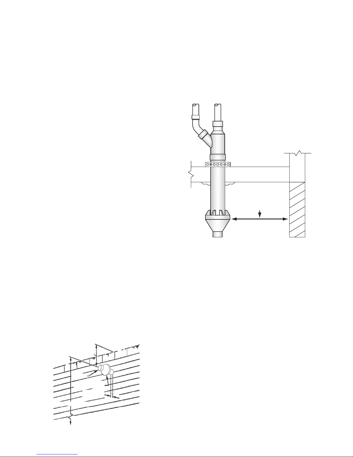
Figure : 28
PLUS HAUT DES DEUX.
HAUT DE NEIGE ANTICIPÉE OU DU SOL, LE
(12 PO) AU DESSUS DU NIVEAU LE PLUS
MAINTENIR UN DÉGAGEMENT DE 30,5 CM
VENTILATION
DE COMBUSTION
ENTRÉE D’AIR
2,5 cm (1 po)
MAXIMUM
MINIMUM 30,5 cm (*12 po)
AVANT-TOIT
33
travers le trou.
s’accumuler à l’intérieur de l’ensemble tuyau lors de l’installation à
REMARQUE : Ne pas laisser l’isolation ou autres matériaux
travers le trou de la structure.
4. Installer le raccord concentrique en Y et l’ensemble tuyau à
ou une mauvaise opération, des blessures corporelles voire la mort.
d’observer cette consigne peut provoquer des dommages au produit
combustion-air et circuler vers l’ouverture du brûleur. Le défaut
L’eau peut aussi s’accumuler à l’intérieur du plus gros tuyau de
ou la recirculation des produits de combustion pourrait se produire.
Figure : 27A
Ne pas faire fonctionner le chauffage sans capuchon contre la pluie
corporelles voire la mort.
Le défaut d’observer cette consigne peut provoquer des blessures
PVC, ce qui permettrait une recirculation des produits de combustion.
des trous adéquats peut causer des fissures aux composants en
le tuyau de ventilation pour la taille de la vis utilisée. Ne pas percer
trou de dégagement dans le capuchon de pluie et un trou pilote dans
Lorsqu’une méthode alternative est utilisée pour visser, percer un
« Figure : 26 ».
lorsqu’un démontage sur site est souhaité pour le nettoyage, voir
fournie sur place pour sécuriser les 2 composants ensemble et ce,
pluie, Il est également possible d’utiliser une vis en acier inoxydable
REMARQUE : Au lieu de cimenter le plus petit tuyau au capuchon de
diamètre de la trousse, voir « Figure : 26 ».
b) Cimenter le capuchon contre la pluie au tuyau de plus petit
avec le diamètre le plus gros, voir « Figure : 19 ».
a) Cimenter le raccord concentrique en Y au tuyau de la trousse
concentrique.
3. Assembler partiellement la trousse de terminaison de ventilation
2. Couper un trou (12,7 cm [5 po] de diamètre).
exigences d’emplacement de la ventilation.
à la page 24) dans ce manuel pour plus d’informations au sujet des
REMARQUE : Voir la section Installation de la ventilation (débutant
ventilation ne seront pas indésirables.
• La trousse de terminaison positionnée où les vapeurs de
des balles, etc.
endommagée ou sujette à des corps étrangers, tels des pierres,
• La trousse de terminaison positionnée où elle ne sera pas
neige légère.
produits de combustion, ou des feuilles en suspension, ou une
par un tourbillon de vent qui peut permettre la recirculation de
• La trousse de terminaison positionnée où elle ne sera pas affectée
équipements de climatisation.
n’endommageront pas les arbustes, les plantes ou des
• La trousse de terminaison positionnée où les vapeurs
un emplacement approprié pour la trousse de terminaison :
REMARQUE : Prendre en considération ce qui suit afin de déterminer
terminaison.
1. Déterminer le meilleur emplacement pour la trousse de
INSTALLATION DE TERMINAISON DANS PAROI LATÉRALE
TERMINAISON CONCENTRIQUE
DÉGAGEMENT TOITURE-TERRASSE DE
TOUTE STRUCTURE.
TOUTE PAROI VERTICALE OU
(10 pieds) DE TOUT PARAPET,
ÊTRE À UN MINIMUM DE 3 m
CONCENTRIQUES DOIVENT
LA OU LES TERMINAISONS
verticales.
standards doivent être utilisées. Voir Installation de terminaisons
verticale ou une structure ne peut être maintenue, des terminaisons
Si cette distance requise de 3 m (10 pi) à un parapet, une paroi
verticale ou structure comme l’indique la Figure 27A.
se trouver à un minimum de 3 m (10 pi) de tout parapet, toute paroi
travers un toit-terrasse, le bouchon d’aération de la terminaison doit
Lors de l’installation d’une terminaison concentrique verticalement à
INSTALLATION SUR TOIT-TERRASSE
ventilation concentrique.
raccordés correctement aux connexions de terminaison de
que les tuyaux d’air de combustion et de ventilation soient
8. Faire fonctionner pendant un cycle de chauffage pour s’assurer
tuyau approprié.
concentrique. Voir « Figure : 27 » pour un raccordement de
du chauffe-eau à l’ensemble terminaison de ventilation
7. Cimenter les tuyaux d’entrée d’air de combustion et de ventilation
raccord en Y.
le tuyau de plus petit diamètre soit cimenté et touche le fond du
petit diamètre dans l’ensemble pénétration du toit. S’assurer que
6. Installer le capuchon contre la pluie et l’ensemble tuyau de plus
qu’illustré à la « Figure : 27 ».
au dessus de a surface du toit ou du niveau de neige anticipé tel
REMARQUE : S’assurer que la hauteur de la terminaison soit
matériaux de support équivalents.
« Figure : 27 » à l’aide du cerclage en métal fourni sur site ou de
5. Fixer l’ensemble à la structure du toit tel qu’illustré dans la
travers le trou.
s’accumuler à l’intérieur de l’ensemble tuyau lors de l’installation à
REMARQUE : Ne pas laisser l’isolation ou autres matériaux
Page 89

32
Figure : 27
COMBUSTION
ENTRÉE D’AIR DE
VENTILATION
pourrait causer une opération intermittente.
PLACE)
COUDE (FOURNI SUR
les tuyaux. Une restriction du débit d’air s’ensuivra et le manostat
Ne pas utiliser d’accouplements fournis sur place pour allonger
(21-1/8 po).
SUR PLACE)
SUPPORT (FOURNI
AU DESSUS DU TOIT.
MAXIMUM DE 61 CM (24 PO)
NIVEAU DE NEIGE ANTICIPÉ
(12 PO) AU DESSUS DU
MINIMUM DE 30,5 CM
MAINTENIR DÉGAGEMENT
SUR PLACE)
FOURREAU/SOLIN (FOURNI
COMBUSTION
ENTRÉE D’AIR DE
Figure : 25
VENTILATION
sur place.
travers le trou de la structure et le fourreau/solin de toit fourni
4. Installer le raccord concentrique en Y et l’ensemble tuyau à
ou une mauvaise opération, des blessures corporelles voire la mort.
99,1 cm (**39 po)
53,7 cm (*21-1/8 po)
DIAMÈTRE 4 po
PVC DIAMÈTRE 3 po
AIR ADMISSION/COMBUSTION
(1-3/16 po)
3 cm
l’allongement ou de la réduction de la dimension 53,7 cm
** La dimension 99,1 cm (39 po) changera en fonction de
30,5 cm (12 po) minimum.
être raccourcie en coupant les tuyaux, fournis dans la trousse, à
(60 po) maximum. La dimension 53,7 cm (21-1/8 po) peut aussi
* La dimension 53,7 cm (21-1/8 po) peut être allongée à 152 cm
(1-1/2 po*)
3,8 cm
d’observer cette consigne peut provoquer des dommages au produit
combustion-air et circuler vers l’ouverture du brûleur. Le défaut
L’eau peut aussi s’accumuler à l’intérieur du plus gros tuyau de
ou la recirculation des produits de combustion pourrait se produire.
Ne pas faire fonctionner le chauffage sans capuchon contre la pluie
corporelles voire la mort.
Le défaut d’observer cette consigne peut provoquer des blessures
Figure : 24
PVC DIAMÈTRE 3 po
VENTILATION/ÉVACUATION
PVC, ce qui permettrait une recirculation des produits de combustion.
des trous adéquats peut causer des fissures aux composants en
le tuyau de ventilation pour la taille de la vis utilisée. Ne pas percer
trou de dégagement dans le capuchon de pluie et un trou pilote dans
Lorsqu’une méthode alternative est utilisée pour visser, percer un
PLUIE
CONTRE LA
CAPUCHON
DIAMÈTRE
SCR-26
2-1/2: TUYAU
EN Y
CONCENTRIQUE
RACCORD
Figure 26.
lorsqu’un démontage sur site est souhaité pour le nettoyage, voir
fournie sur place pour sécuriser les 2 composants ensemble et ce,
pluie, Il est également possible d’utiliser une vis en acier inoxydable
DIAMÈTRE 4 po
TUYAU SCR-26
REMARQUE : Au lieu de cimenter le plus petit tuyau au capuchon de
Figure : 26
(FOURNIE SUR PLACE)
VIS EN ACIER INOXYDABLE
des gants de travail.
Suivre tous les codes de sécurité. Porter des lunettes de sécurité et
l’appareil doivent être observées.
dans la littérature, sur les plaques, et sur les étiquettes apposées sur
technicien de service qualifié, voir page 7. Toutes les mises en garde
capacités équivalentes à celles d’un installateur qualifié ou d’un
et l’entretien de terminaison de ventilation concentrique exige des
risqué à cause des composants au gaz et électriques. L’installation
L’installation et l’entretien de l’équipement du chauffe-eau peut être
PILOTE DANS TUYAU DE VENTILATION.
CAPUCHON CONTRE LA PLUIE ET TROU DE
PERCER TROU DE DÉGAGEMENT DANS
diamètre de la trousse, voir Figure 26.
b) Cimenter le capuchon contre la pluie au tuyau de plus petit
avec le diamètre le plus gros, voir Figure 24.
a) Cimenter le raccord concentrique en Y au tuyau de la trousse
concentrique.
3. Assembler partiellement la trousse de terminaison de ventilation
2. Couper un trou (5 po de diamètre).
ventilation sont moins visibles.
risques aux contaminants d’admission et que les vapeurs de
CONSIDÉRATIONS DE SÉCURITÉ
utilisée avec des systèmes de tuyaux de 3 po de diamètre.
Cette trousse de terminaison de ventilation concentrique peut être
l’installation.
Des tuyaux et raccords fournis sur place sont requis pour compléter
Instructions d’installation 196151 1
Raccord concentrique en Y 3 po 1
Tuyau SDR-26 Dia. 2-1/2 po 1
Tuyau SDR-26 Dia. 4 po 1
Capuchon contre la pluie 3 po 1
Article Description Qté
qu’elle est moins susceptible aux dégâts, qu’elle a de moindres
REMARQUE : Une terminaison de toit est préférable étant donné
terminaison.
1. Déterminer le meilleur emplacement pour la trousse de
TOIT
INSTALLATION DE TERMINAISON VERTICALE SUR LE
TABLE 8 – COMPOSANTS DE LA TROUSSE
instructions ci dessous pour des installations adéquates.
la trousse de ventilation concentrique #9006328005. Suivre les
Ce chauffe-eau est certifié pour une ventilation concentrique avec
INSTALLATION DE VENTILATION CONCENTRIQUE
Page 90

31
Figure : 22 Figure : 23
ANTICIPÉ OU DU SOL
PLUS HAUT NIVEAU DE NEIGE
30,5 cm (12 po) AU DESSUS DU
DÉGAGEMENT MINIMUM DE
CONCENTRIQUE
VENTILATION
SOL
NIVEAU DU
MAXIMUM 2,5 cm (1 po)
NIVEAU DU SOL
VERS LE HAUT
D’ENTRÉE DOIT FAIRE FACE
IMPORTANT : LE POINT
Figure : 21
D’ENTRÉE
INTAKE TERMINAL.
MUST BE AT SAME LEVEL OR ABOVE
NIVEAU OU AU DESSUS QUE LE TERMINAL
24” MINIMUM SEPARATION. EXHAUST
L’ÉVACUATION DOIT ÊTRE AU MÊME
SÉPARATION MINIMUM DE 61 cm (24 po)
LATÉRALE
VENTILATION À PAROI
OPTION)
(EN
NIVEAU DE NEIGE ANTICIPÉ OU DU SOL
(12 po) AU DESSUS DU PLUS HAUT
DÉGAGEMENT MINIMUM DE 30,5 cm
2,5 cm (1 po)
MINIMUM
NIVEAU DU SOL
PURGEUR
AU DRAIN
(1 po)
MAXIMUM 2,5 cm
Figure : 20
TOIT
SNOW LEVEL
NIVEAU DE NEIGE ANTICIPÉ
ABOVE HIGHEST ANTICIPATED
(12 po) AU DESSUS DU PLUS HAUT
12” MINIMUM CLEARANCE
DÉGAGEMENT MINIMUM DE 30,5 cm
VENTILATION CONCENTRIQUE
TOIT
ANTICIPATED SNOW LEVEL
DU PLUS HAUT NIVEAU DE NEIGE ANTICIPÉ
12” MINIMUM CLEARANCE ABOVE HIGHEST
DÉGAGEMENT MINIMUM DE 30,5 cm (12 po) AU DESSUS
MINIMUM 15,2 cm (6 po)
ÉVENT DE TOIT
ARRIVÉE
ÉVACUATION
SCHÉMA VENTILATION DIRECTE
Page 91

30
Figure : 18
ventilation verticale sont nécessaires pour des unités à ventilation directe.
REMARQUE : Un mur avec une bouche d’entrée d’air ou des installations avec
Figure : 19
AIR D’ADMISSION ET/OU VENTILATION (ÉCHAPPEMENT)
DES TERMINAISON(S) VERTICALE(S)
DÉGAGEMENT DES TOITURES-TERRASSES
CLIGNOTEMENT
MOYENNES
DE NEIGE
BOUCHE D’ENTRÉE D’AIR
NIVEAU DE NEIGE ANTICIPÉ
DESSUS DU TOIT OU DU
A&B : 30,5 cm (12 po) AU
D’AIR
D’ENTRÉE
BOUCHE
LES DEUX TUYAUX
PLOMBERIE (TYP)
FOURREAU DE
DES CHUTES
AU-DESSUS
30,5 cm (12 po)
Figure : 17
(24 po)
MINIMUM 61 cm
CLIGNOTEMENT
TOUS LES MODES
D’AIR
D’ÉVACUATION
VENTILATION
BOUCHE DE
MOYENNES
DE NEIGE
DES CHUTES
AU-DESSUS
(12 po)
30,5 cm
BOUCHE DE VENTILATION D’ÉVACUATION D’AIR
TERMINAISON DE VENTILATION VERTICALE
de 3 m (10 pi) horizontalement. Voir Figure 19.
au-dessus de tout parapet, mur vertical ou toute structure à moins
d’air et d’évacuation d’air doivent être au moins à 61 cm (24 po)
Pour les installations sur toits-terrasses, les terminaisons d’entrée
INSTALLATION SUR TOIT-TERRASSE
ILLUSTRÉE ICI
D’ENTRÉE D’AIR
TERMINAISON
REMARQUE :
3 m (10 pi) HORIZONTALEMENT.
STRUCTURE DANS LES
PAROI VERTICALE OU DE TOUTE
TOUT PARAPET, DE TOUTE
61 cm (24 po) AU-DESSUS DE
TROUVER À UN MINIMUM DE
VENTILATION DOIVENT SE
D’AIR D’ADMISSION ET/OU DE
LA OU LES TERMINAISONS
61 cm (24 po) AU-DESSUS
HAUTEUR MINIMUM DE
3 m (10 pi)
SI MOINS DE
d’évacuation d’air. Voir Figure 17 et Figure 18.
terminaison d’entrée d’air et entre l’axe central de la terminaison
4. Prévoir au moins 61 cm (24 po) entre l’axe central de la
d’air doivent pénétrer le même côté du toit.
3. La terminaison d’entrée d’air et la terminaison d’évacuation
dans un fourreau protecteur ou un solin équivalent.
2. Les terminaisons verticales sur le toit doivent être scellées
saillie à travers le toit.
1. Fournir un support adéquat pour tous les tuyaux qui sont en
DU TERMINAL DOIVENT ÊTRE SUIVIES.
SPÉCIFICATIONS SUIVANTES AU SUJET DE L ’EMPLACEMENT
AVEC UNE TERMINAISON À TRAVERS UN TOIT, LES
VERTICALE
INSTALLATION D’UNE BOUCHE DE VENTILATION
Page 92

30 cm (12 po) ‡
29
porche, terrasse ou balcon
M
Dégagement sous véranda,
* Dégagement conforme aux codes d’installation locaux et aux exigences du fournisseur de gaz et aux instructions d’installation du fabricant.
‡ Permis uniquement si véranda, porche, terrasse ou balcon sont complètement ouverts au moins sur deux côtés sous le sol.
adjacentes.
† Une ventilation ne doit pas se terminer dans des endroits où elle peut provoquer des risques d’accumulation de gel ou de glace sur les surfaces de propriétés
1 Conformément au Code d’installation du gaz naturel et du propane actuel CSA B149.1.
G
Dégagement du coin intérieur 45 cm (18 po)*
F
Dégagement d’un coin extérieur 60 cm (2 pi)*
située sur une propriété publique
L
2,13 m (7 pi)†
1,83 m (6 pi)
(30 kW)
pour les appareils de plus de 100 000 Btu/h
et 100 000 Btu/h (30 kW), 91 cm (36 po)
les appareils entre 10 000 Btu/h (3 kW)
10 000 Btu/h (3 kW), 30 cm (12 po) pour
15 cm (6 po) pour les appareils jusqu’à
91 cm (3 pi)
régulateur
(15 pi) au-dessus de l’ensemble compteur/
91 cm (3 pi) dans une hauteur de 4,5 m
1
INSTALLATIONS POUR LE CANADA
trottoir pavé ou une d’allée pavée
Dégagement au-dessus d’un
d’alimentation en air mécanique
K
Dégagement d’une entrée
tout autre appareil
arrivée d’air de combustion vers
J
mécanique dans le bâtiment ou
d’alimentation en air non
Dégagement d’une entrée
service
I
ventilation du régulateur de
Dégagement de la sortie de
régulateur
dessus de l’ensemble compteur/
H
la ligne médiane prolongé auDégagement de chaque côté de
1
30 cm (12 po)*
30 cm (12 po)*
15 cm (6 po)*
(30 kW)
pour les appareils de plus de 100 000 Btu/h
et 100 000 Btu/h (30 kW), 91 cm (36 po)
les appareils entre 10 000 Btu/h (3 kW)
10 000 Btu/h (3 kW), 30 cm (12 po) pour
15 cm (6 po) pour les appareils jusqu’à
30 cm (12 po)
INSTALLATIONS POUR LE CANADA
ventilé
E
Dégagement d’un soffite non
ligne médiane de la bouche
horizontale de 61 cm (2 pi) de la
D
bouche en dedans d’une distance
ventilé situé au-dessus de la
Dégagement vertical d’un soffite
en permanence
C
Dégagement d’une fenêtre fermée
ouverte
B
d’une porte susceptible d’être
Dégagement d’une fenêtre ou
balcon
A
véranda, porche, terrasse ou
Dégagement au-dessus du sol,
l’air extérieur pour la combustion.
Dégagements de la bouche de ventilation pour les installations à ventilation directe. Configurations de ventilation directe utilisent
Figure : 16
V X
TERMINAISON DE VENTILATION BOUCHE D’ADMISSION D’AIR ZONE DANS LAQUELLE BORNE N’EST PAS PERMISE
B
A
K
V
X
M
H
J
X
FERMÉ
FIXE
V
B
V
B
V
UTILISABLE
F
B
B
A
V
UTILISABLE
FERMÉ
FIXE
C
V
V
v
B
E
L
v
D
G
COIN INTÉRIEUR
DÉTAIL DE
DÉGAGEMENTS EXTÉRIEURS POUR TERMINAISON DE VENTILATION LATÉRALE
(emploi d’air extérieur pour combustion)
VENTILATION DIRECTE
RÈGLES D’IMPLANTATION D’UN TERMINAL MURAL À VENTILATION DIRECT
Page 93

30 cm (12 po) ‡
28
porche, terrasse ou balcon
M
Dégagement sous véranda,
* Dégagement conforme aux codes d’installation locaux et aux exigences du fournisseur de gaz et aux instructions d’installation du fabricant.
‡ Permis uniquement si véranda, porche, terrasse ou balcon sont complètement ouverts au moins sur deux côtés sous le sol.
adjacentes.
† Une ventilation ne doit pas se terminer dans des endroits où elle peut provoquer des risques d’accumulation de gel ou de glace sur les surfaces de propriétés
1 Conformément au Code d’installation du gaz naturel et du propane actuel CSA B149.1.
G
Dégagement du coin intérieur 45 cm (18 po)*
F
Dégagement d’un coin extérieur 60 cm (2 pi)*
située sur une propriété publique
L
2,13 m (7 pi)†
1,83 m (6 pi)
(30 kW)
pour les appareils de plus de 100 000 Btu/h
et 100 000 Btu/h (30 kW), 91 cm (36 po)
les appareils entre 10 000 Btu/h (3 kW)
10 000 Btu/h (3 kW), 30 cm (12 po) pour
15 cm (6 po) pour les appareils jusqu’à
91 cm (3 pi)
régulateur
(15 pi) au-dessus de l’ensemble compteur/
91 cm (3 pi) dans une hauteur de 4,5 m
1
INSTALLATIONS POUR LE CANADA
trottoir pavé ou une d’allée pavée
Dégagement au-dessus d’un
d’alimentation en air mécanique
K
Dégagement d’une entrée
tout autre appareil
arrivée d’air de combustion vers
J
mécanique dans le bâtiment ou
d’alimentation en air non
Dégagement d’une entrée
service
I
ventilation du régulateur de
Dégagement de la sortie de
régulateur
dessus de l’ensemble compteur/
H
la ligne médiane prolongé auDégagement de chaque côté de
1
30 cm (12 po)*
30 cm (12 po)*
30 cm (12 po)*
(30 kW)
pour les appareils de plus de 100 000 Btu/h
et 100 000 Btu/h (30 kW), 91 cm (36 po)
les appareils entre 10 000 Btu/h (3 kW)
10 000 Btu/h (3 kW), 30 cm (12 po) pour
15 cm (6 po) pour les appareils jusqu’à
30 cm (12 po)
INSTALLATIONS POUR LE CANADA
ventilé
E
Dégagement d’un soffite non
ligne médiane de la bouche
horizontale de 61 cm (2 pi) de la
D
bouche en dedans d’une distance
ventilé situé au-dessus de la
Dégagement vertical d’un soffite
en permanence
C
Dégagement d’une fenêtre fermée
ouverte
B
d’une porte susceptible d’être
Dégagement d’une fenêtre ou
balcon
A
véranda, porche, terrasse ou
Dégagement au-dessus du sol,
pulsé utilisent l’air ambiant pour la combustion.
Dégagements de la bouche de ventilation pour les installations à ventilation à air pulsé. Les configurations de ventilation à air
Figure : 15
V X
TERMINAISON DE VENTILATION BOUCHE D’ADMISSION D’AIR ZONE DANS LAQUELLE BORNE N’EST PAS PERMISE
B
A
K
V
X
M
H
J
X
FERMÉ
FIXE
V
B
V
B
V
UTILISABLE
F
B
B
A
V
UTILISABLE
FERMÉ
FIXE
C
V
V
v
B
E
L
v
D
G
COIN INTÉRIEUR
DÉTAIL DE
DÉGAGEMENTS EXTÉRIEURS POUR TERMINAISON DE VENTILATION LATÉRALE
(emploi d’air ambiant pour combustion)
VENTILATION À AIR PULSÉ
TERMINAISON DÉGAGEMENTS PAROI LATÉRALE VENTILATION À AIR PULSÉ
Page 94

MINIMUM
30,5 cm (12 po)
CONSTRUCTION
DU MUR DE
EXTÉRIEUR
Figure : 14
BOUCHE D’ENTRÉE D’AIR - TOUS LES MODÈLES
EN PVC
RACCORDEMENT
EAU
DU
CHAUFFE-
27
cercle marqué.
ouverture d’environ 1,3 cm (1/2 po) plus large que le
A.) MURS LATÉRAUX EN MAÇONNERIE Buriner une
gabarit.
à l’aide des trous percés comme point de centrage pour le
Le gabarit peut maintenant être positionné sur le mur extérieur
travers le centre du gabarit à partir de l’intérieur vers l’extérieur.
l’intérieur et l’extérieur. Aligner les trous en perçant un trou à
être plus facile de marquer les deux côtés du mur, à savoir
ventilation sont installés sur l’extérieur d’un mur fini, il pourrait
DISSIMULÉS À L’INTÉRIEUR DU MUR. Si les terminaux de
travers le mur. FAIRE ATTENTION AU CÂBLAGE ET TUYAUX
les trous pour les tuyaux de ventilation qui doivent passer à
installer des plaques-couvercle comme gabarit pour marquer
1. Une fois que les points de terminaison ont été déterminés,
SÉQUENCE D’INSTALLATION
D’AIR AVEC GRILLE
D’ÉVACUATION
BOUCHE
PLAQUES DE METAL
D’AIR AVEC GRILLE
BOUCHE D’ENTRÉE
PLAQUES DE METAL
CONSTRUCTION
DU MUR DE
EXTÉRIEUR
MORTIER
EN SILICONE OU
CALFEUTRAGE
BOUCHE D’ÉVACUATION D’AIR - TOUS LES MODÈLES
EN PVC
RACCORDEMENT
EAU
CHAUFFE-
DU
D’AIR
BOUCHE D’ENTRÉE
MORTIER
EN SILICONE OU
CALFEUTRAGE
Figure 14).
d’airfinisse pointée dans la bonne position (Figure 13A et
l’autre côté du mur, en s’assurant que la bouche d’entrée
tuyau à travers le mur et l’insérer dans l’accouplement sur
pour être collé avant de l’insérer à travers le mur. Glisser le
mur, le tuyau avec la bouche d’entrée d’air peut être préparé
avec un accouplement sur l’extrémité contre l’ouverture du
6. Si le tuyau d’entrée d’air est installé pour arriver jusqu’au mur,
l’installation.
sur l’arrière de la plaque pour la tenir contre le muri après
entre le tuyau et le mur. Placer une quantité du calfeutrage
5. Placer un cordon de calfeutrage (non fourni) autour de l’écart
contre la bouche d’entrée d’air.
4. Glisser la plaque du mur par-dessus le tuyau pour qu’elle s’arrête
3. Coller la bouche d’entrée d’air à la section du tuyau.
long que l’épaisseur du mur à l’ouverture.
2. Couper une longueur de tuyau d’environ 8,9 cm (3,5 po) plus
étape sur le mur intérieur s’il y a lieu.
couvercle de la bouche de ventilation.) Répéter cette
L’écart qui en découlera sera couvert par les plaquesde ventilation de glisser facilement à travers l’ouverture.
(1/4 po) à l’extérieur de la ligne. (Ceci permettra au tuyau
autour du cercle marqué en restant à environ 0,64 cm
toutes les scies ou la lame de scie sauteuse. Couper
Ce trou pilote est utilisé comme point de départ pour
d’environ 0,64 cm (1/4 po) à l’extérieur du cercle marqué.
B.) MURS LATÉRAUX EN BOIS Percer un trou pilote
Figure : 13A
61 cm (24 po) MIN.
Grille d’entrée d’air
LATÉRALE
PAROI
D’ÉVACUATION D’AIR
VENTILATION
BOUCHE DE
maximale pratique entre ces deux bouches est recommandée.
vers l’entrée d’air dans des endroits venteux/froids, une distance
Remarque : pour empêcher que les produits d’évacuation circulent
de 2 po avec un grillage maillé.
et la bouche d’évacuation d’air est un accouplement droit en PVC
d’air est un coude en pvc de 2 po 90° avec une grille d’entrée d’air
d’entrée d’air et une bouche d’évacuation d’air. La bouche d’entrée
Cet appareil comprend deux bouches de ventilation - une bouche
collé à l’entrée d’air (voir Figure 13) fournie sur l’appareil.
d’entrée d’air doit être enlevée. Le tuyau d’entrée d’air peut être
Lorsque l’appareil est configuré avec ventilation directe, la grille
Figure 13 : GRILLE D’ENTRÉE D’AIR
d’air du ventilateur
Ensemble de l’arrivée
afin d’empêcher les grosses particules d’entrer dans l’appareil.
L’entrée d’air fournie sur l’appareil contient une grille d’entrée d’air
DIRECTE
INSTALLATION D’UNE BOUCHE DE VENTILATION
Page 95

30,5 CM MIN. (1 PI)
AVEC GRILLE
BOUCHE DE VENTILATION
DE CONSTRUCTION
EXTÉRIEUR DU MUR
(OPTIONNELLE)
PLAQUE MURALE
26
Figure 12 : TERMINAISON DE VENTILATION
EN PVC
RACCORDEMENT
EAU
DU CHAUFFE-
OU MORTIER
EN SILICONE
CALFEUTRAGE
pointer dans la bonne position, voir la Figure 12.
côté du mur, en s’assurant que la bouchede ventilation finit par se
le tuyau à travers le mur et l’insérer dans l’accouplement sur l’autre
préparé pour être collé avant de l’insérer à travers le mur. Glisser
l’ouverture du mur, le tuyau à la bouche de ventilation peut être
arriver jusqu’au mur, avec un accouplement sur l’extrémité contre
après l’installation. Si le tuyau de ventilation est installé pour
calfeutrage sur l’arrière de la plaque pour la tenir contre la paroi
un peu d’écart entre le tuyau et la paroi. Placer une quantité du
tuyau et la plaque-couvercle. En mettre suffisamment pour combler
un cordon de calfeutrage (non fourni) autour de l’écart entre le
maximum - m (pi.)
Tuyau 3 po
Tuyau 2 po
TABLE 7
tuyau pour qu’elle s’arrête contre la bouche de ventilation. Placer
à cette section du tuyau. Glisser la plaque du mur par-dessus le
que l’épaisseur du mur à l’ouverture. Coller la bouche de ventilation
Couper une longueur de tuyau d’environ 8,9 cm (3,5 po) plus long
Répéter cette étape sur le mur intérieur s’il y a lieu.
couvert par la plaque de finition de la bouche de ventilation.)
facilement à travers l’ouverture. L’écart qui en découlera sera
à l’extérieur de la ligne. (Ceci permettra à l’évent de glisser
autour du cercle marqué en restant à environ 0,64 cm (1/4 po)
pour toutes les scies ou la lame de scie sauteuse. Couper
cercle marqué. Ce trou pilote est utilisé comme point de départ
Percer un trou pilote d’environ 0,64 cm (1/4 po) à l’extérieur du
A) MURS LATÉRAUX EN BOIS
le cercle marqué.
Buriner une ouverture d’environ 1,3 cm (1/2 po) plus large que
3. A) MURS LATÉRAUX EN MAÇONNERIE
pour le gabarit.
mur extérieur à l’aide du trou percé comme point de centrage
l’extérieur. Le gabarit peut maintenant être positionné sur le
trou à travers le centre du gabarit à partir de l’intérieur vers
à savoir l’intérieur et l’extérieur. Aligner les trous en perçant un
fini, il pourrait être plus facile de marquer les deux côtés du mur,
2. Si la bouche de ventilation est installée sur l’extérieur d’un mur
MUR.
AU CÂBLAGE ET TUYAUX DISSIMULÉS À L’INTÉRIEUR DU
ventilation qui doit passer à travers le mur. FAIRE ATTENTION
couvercle comme gabarit pour marquer le trou pour le tuyau de
1. Installer la bouche de ventilation en utilisant une plaque-
LATÉRALE
INSTALLATION DE LA BOUCHE DE VENTILATION, PAROI
VENTILATION VERTICALE.
consulter la section intitulée INSTALLATION D’UNE BOUCHE DE
Si vous installez votre système de sorte qu’il ventile à travers le toit,
HORIZONTAL À TRAVERS LE MUR
INSTALLATION D’UN SYSTÈME DE VENTILATION
6 4,57 (15) 28,95 (95)
5 6,09 (20) 30,48 (100)
4 7,62 (25) 32 (105)
3 9,14 (30) 33,52 (110)
2 10,66 (35) 35,05 (115)
1 12,19 (40) 36,57 (120)
maximum - m (pi.)
à 90°
fournie dans la trousse de ventilation.
40 DWV) doit être obtenue. Une grille de 3 po de diamètre est
de ventilation de raccord de 3 po (fourni localement - Norme
pi x 3 po pour acquérir le diamètre de tuyau désiré. Une bouche
coude d’évacuation avant d’ajouter un raccord réducteur de 2
tuyau de diamètre de 2 po doit être inséré et collé à l’ensemble
Si un tuyau de ventilation de 3 po est utilisé : 5,1 cm (2 po) de
l’ensemble coude d’évacuation.
de ventilation d’un diamètre de 2 po doit être inséré et collé à
Si un tuyau de ventilation de 2 po est utilisé : Un tuyau
coudes illustrés dans la Table 7.
du système ne doit pas dépasser les longueurs et le nombre de
avec un écran installé, est censée être dans le système et le reste
dessus sont exclusifs de la terminaison. Ceci dit, la terminaison,
REMARQUE : Les pieds (m) équivalents du tuyau indiqués citerminaison appropriée.
pour l’entrée d’air et la ventilation d’évacuation respectivement et la
est un coude de 90° plus 0,61 m et 2,1 m (2 pi et 7 pi) de tuyau droit
La longueur de ventilation minimale pour chaque grosseur de tuyau
Nombre de coudes
pieds équivalents de tuyau tel qu’indiqué dans la Table 7.
2. Ce chauffe-eau est capable de ventiler des gaz de carneau en
coudes.
de sorte à utiliser un minimum de tuyaux de ventilation et de
1. Faire un plan d’implantation du réseau de tuyaux de ventilation
de ventilation.
du coude d’évacuation jusqu’à l’emplacement prévu du terminal
Planifier la trajectoire du réseau de tuyaux de ventilation à partir
VENTILATION
PLANIFICATION DU RÉSEAU DE TUYAUX DE
Code ainsi qu’aux codes locaux.
INSTALLATION DU CHAUFFE-EAU, et au National Fuel Gas
à prendre en considération concernant l’emplacement et
à l’information contenue dans ce manuel dans la section Faits
aux matières combustibles doivent être fournis conformément
étant des raccords d’évent. Les dégagements requis par rapport
forcée sont classifiés par les codes de construction comme
Les tuyaux de ventilation utilisés pour les chauffe-eau à ventilation
plomberie et du câblage.
dégagements appropriés soient maintenus au niveau de la
Planifier la configuration du système de ventilation afin que des
« Figure : 14 ».
une paroi latérale sont fournies à la Figure 12, « Figure : 13A », et
Les instructions concernant une installation appropriée à travers
« Figure : 15 » et « Figure : 16 ».
d’installation du gaz naturel et du propane (CAN/CSA B149.1). V oir
mentionné dans les codes locaux ou l’édition courante du Code
à ce que les dégagements appropriés soient maintenus tel que
Le réseau de tuyaux de ventilation doit se terminer de manière
qu’illustré dans la « Figure : 15 » et « Figure : 16 ».
qu’illustré dans la Figure 12 et « Figure : 14 » ou à travers le toit tel
La ventilation pourrait se terminer à travers une paroi latérale tel
se terminera. Voir Figure 12, « Figure : 13A », et « Figure : 14 ».
La première étape est de déterminer où le tuyau de ventilation
TERMINAISON DU TUYAU DE VENTILATION
Page 96

25
Bouche(s)
Bouche(s)
(Ventilation directe seulement)
ISELL0387 & IASPP03 pour l’entrée
ISVL03 & IASPP03 pour l’évacuation;
(Ventilation directe seulement)
ISELL0287 & IASPP02 pour l’entrée
ISVL02 & IASPP02 pour l’évacuation;
ventilation
Matériau de
(Ventilation directe seulement)
3PPS-E90 & 3PPS-BG pour l’entrée
3PPS & 3PPS-BG pour l’évacuation;
(Ventilation directe seulement)
2PPS-E90 & 2PPS-BG pour l’entrée
2PPS & 2PPS-BG pour l’évacuation;
ventilation
Matériau de
90 degrés
Coude de
TABLE 6
90 degrés
Coude de
TABLE 5
IAFC03 IANS03 ISELL0387 ISVL03
IAFC02 IANS02 ISELL0287 ISVL02
connecteur
Anneau
Centrotherm InnoFlue SW
connecteur
Anneau
M & G Duravent PolyPro
d’adaptateur
Connecteur
d’adaptateur
Connecteur
0303
ISAGL
0202
ISAGL
combustion
de sortie de
Adaptateur
combustion
de sortie de
Adaptateur
3 po
2 po
tuyau
nominal du
Diamètre
3 po 3PPS-AD PPS-PAC 3PPS-LB 3PPS-E90 3PPS
2 po 2PPS-AD PPS-PAC 2PPS-LB 2PPS-E90 2PPS
tuyau
nominal du
Diamètre
de 2 po et 3 po de diamètre.
ventilation en polypropylène, pour renforcer les joints des tuyaux
anneaux connecteurs du joint en métal, disponible du fabricant de
les exigences du fabricant du chauffe-eau, vous devez utiliser les
Afin d’être pleinement conforme à ULC-S636 et pour satisfaire
système de ventilation.
est fourni par le fabricant de la ventilation afin de l’adapter à son
spécifique au niveau de la connexion du carneau. L’adaptateur
L’installateur doit utiliser un adaptateur de démarreur de ventilation
avec des connecteurs de joints du fabricant de la ventilation.
scellant. Toutes les connexions de ventilation DOIVENT être fixées
Ne pas tenter de raccorder le polypropylène avec du ciment
utilisent une méthode pour pousser ensemble le joint d’étanchéité.
ciment pour raccorder les sections de tuyau et de coude mais
Les systèmes de ventilation en polypropylène n’utilisent pas de
voire la mort ou d’importants dommages matériels.
cette consigne peut entraîner des blessures corporelles graves
ventilation de différents types ou fabricants. Le défaut d’observer
dans les Tables ci-dessous. NE PAS mélanger des systèmes de
Utiliser uniquement les adaptateurs et système de ventilation listés
pourrait entraîner une défaillance du tuyau de ventilation.
augmentation des températures du mur de ventilation, ce qui
ventilation en polypropylène. L’utilisation d’isolation causera une
L’isolation ne devrait pas être utilisée sur les matériaux de
nombre de coudes qui peuvent être utilisés.
la page 26 afin de déterminer la longueur de tuyau maximale et le
les instructions du fabricant de la ventilation. Consulter la Table 7 à
Polypropylène). Ces produits listés doivent être installés en suivant
fabricants spécifiques (Éco-systèmes Centrotherm et DuraVent
à paroi simple, rigide, non-concentrique est offert par deux
Table 6. L’application de matériau de ventilation en polypropylène
de ventilation en polypropylène tel qu’illustré dans la Table 5 et la
Le chauffe-eau a été approuvé pour être installé avec du matériau
INST ALLATIONS AVEC POL YPROPYLÈNE
Page 97

24
ce manuel pour de plus amples informations.
téléphone de support technique indiqué sur la couverture arrière de
du reste de la tuyauterie d’entrée d’air frais. Appeler le numéro de
d’entrée d’air près du ventilateur avant de procéder à l’installation
dispositif anti-refoulement soit installé au niveau de la bouche
de tuyauterie d’admission d’air frais, il est recommandé qu’un
peut provenir d’air ambiant extrêmement froid à travers un système
Pour une application à ventilation directe où l’air de combustion
de cheminée et créent un risque d’asphyxie.
de suie dans la chambre de combustion, les brûleurs et les tubes
des gaz de fumée. Lesdites conditions provoquent une formation
respectées pour éviter toute combustion réduite ou recirculation
Les instructions figurant dans cette section du manuel doivent être
l’extérieur.
Ne jamais faire fonctionner le chauffe-eau sans ventilation vers
permettre la vidange de la condensation.
minimum de 21 mm/m (1/4 po/pi) vers l’arrière du chauffe-eau pour
Tous les tuyaux de ventilation (évacuation) doivent être inclinés au
CPVC ou polypropylène.
on recommande l’utilisation de raccordements et de tuyaux en
dont les températures ambiantes sont au-dessus de 38 °C (100 °F)
Toujours lire et s’assurer de bien comprendre le manuel d’instructions.
REMARQUE : Pour les chauffe-eaux situés dans des emplacements
avant d’effectuer l’installation et la mise en service du chauffe-eau.
conformément aux instructions de ventilation de ce manuel, et ce,
Si l’une de ces conditions est détectée, elle doit être corrigée
d’un mauvais alignement de tout composant dans le système.
signe d’affaissement ou autres tensions dans les joints à la suite
et parcours du tuyau de ventilation. Vérifier le système pour tout
notamment au niveau des joints entre les coudes et autres raccords
complet pour vous assurer de l’absence de fissures ou cassures,
été respectés. Inspecter soigneusement le réseau de ventilation au
et l’emplacement du terminal tel que détaillés dans ce manuel ont
été utilisé, et que les longueurs d’évent minimales et maximales
d’installation. S’assurer que le bon matériel détaillé ci-dessus a
ventilation existant doit être effectuée avant de faire tous travaux
ventilation préexistant, une inspection approfondie du réseau de
chauffage à ventilation forcée existant dans un système de
Si le chauffe-eau est installé comme un remplacement d’un
comme étant conformes à ULC S636.
PVC/CPVC et des tuyaux en Polypropylène certifiés et marqués
Ce chauffe-eau a été certifié pour être ventilé avec des tuyaux en
transversale ouverte de la ventilation.
et, par conséquent, diminue la surface de section
pas piégé dans une section du tuyau de ventilation
intégralité pour s’assurer que le condensat ne sera
• Analyser le réseau de tuyaux de ventilation dans son
d’explosion ou d’asphyxie.
risque de mauvais fonctionnement, d’incendie,
alimentation en air adéquate et ce, pour éviter tout
ventilation vers l’extérieur et sans avoir une
• Ne jamais faire fonctionner le chauffe-eau sans
sont disponibles.
• Des détecteurs de gaz et de monoxyde de carbone
chimiques à proximité du chauffe-eau.
• Ne pas placer des produits qui émettent des vapeurs
une enveloppe isolante.
• Ne pas obstruer l’entrée d’air du chauffe-eau avec
suie.
• Ne pas faire fonctionner en cas d’accumulation de
par une inondation.
• Ne pas utiliser le chauffe-eau s’il a été endommagé
ces instructions et aux codes locaux.
• Installer le système de ventilation conformément à
de ventilation soient homologués ULC S636.
courante), lequel exige que les composants du réseau de tuyaux
B149.1 - Code d’installation du gaz naturel et du propane (édition
AVERTISSEMENT
L’installation de ce chauffe-eau doit se conformer au CAN/CSA
29 respectivement.
consulter « Figure : 15 » et « Figure : 16 » à la page 28 et la page
l’entrée d’air de combustion et la bouche d’évacuation d’air,
de combustion, maintenir autant de distance que possible entre
lors des temps très froids. Pour éviter la recirculation des gaz
développera de la suie et du gel dans l’entrée d’air à combustion
des gaz de combustion. La recirculation de gaz de cheminée
les atriums, et les coins intérieurs peut entraîner une recirculation
La ventilation directe dans des espaces clos tels que les allées,
de ventilation près des trottoirs, fenêtres et entrées de bâtiment.
doit être apportée avant de choisir l’emplacement de terminaison
sortie du réseau de ventilation du bâtiment. Une attention spéciale
de combustion se condense en un nuage de vapeur à l’endroit de la
Dans les climats froids, toute la vapeur d’eau restant dans les gaz
de l’extérieur, voir « Figure : 20 » & « Figure : 21 » à la page 31.
la tuyauterie pour amener l’air de combustion au chauffe-eau
ventilation verticale pour évacuer les produits de combustion et
4. Ventilation directe verticale - en utilisant une terminaison de
l’extérieur. Voir « Figure : 14 » à la page 27.
tuyauterie pour amener l’air de combustion au chauffe-eau de
travers le mur pour évacuer les produits de combustion et la
3. Ventilation directe horizontale - en utilisant la terminaison à
12 : TERMINAISON DE VENTILATION » à la page 26.
horizontale directement à travers un mur extérieur, voir « Figure
2. Terminaison à travers le mur - terminaison de ventilation
la page 30.
consulter Installation d’une bouche de ventilation verticale à
les endroits fermés et non fermés avec pénétration au toit,
1. Terminaison verticale - terminaison de ventilation verticale par
installation. Ces orientations sont :
doit décider quelle méthode est plus appropriée pour chaque
selon les exigences du bâtiment et du chauffe-eau. L’installateur
Ce chauffe-eau peut être installé en 4 orientations différentes
pour la combustion provienne de l’extérieur par un tuyau scellé.
combustion, ou peut être directement ventilé afin que l’air d’entrée
Ce chauffe-eau peut être ventilé en utilisant l’air de la pièce pour la
VENTILATION
CONSIDÉRATIONS DE L’INSTALLATION DE
L’inhalation de monoxyde de carbone peut causer des lésions au cerveau ou la mort.
Risque respiratoire – Gaz de monoxyde de carbone
INSTALLATION DE LA VENTILATION
Page 98

23
raccordements. Réparer au besoin.
4. Vérifier l’étanchéité de toute la tuyauterie d’eau et les
la tuyauterie.
constant. Ceci permettra à l’air de sortir du chauffe-eau et de
proche. Laisser l’eau couler jusqu’à obtenir un écoulement
à l’air de sortir en ouvrant le robinet d’eau chaude le plus
3. Pour s’assurer du remplissage complet du réservoir, permettre
rester ouvert lorsque le chauffe-eau est en service.
REMARQUE : Le robinet d’alimentation en eau froide doit
2. Ouvrir le robinet d’alimentation en eau au chauffe-eau.
situe sur le côté avant inférieur du chauffe-eau.
poignée vers la droite (sens horaire). Le robinet de vidange se
1. Fermer le robinet de vidange du chauffe-eau en tournant la
Pour remplir le chauffe-eau d’eau :
robinet d’eau chaude avant d’allumer le gaz au chauffe-eau.
réservoir, ce dernier doit être rempli d’eau. L’eau doit s’écouler du
complètement rempli d’eau. Pour prévenir des dommages au
Ne jamais faire fonctionner ce chauffe-eau s’il n’est pas
5HPSOLUOHUpVHUYRLUG¶HDXDYDQWGHIDLUHIRQFWLRQQHU
eYLWHUOHVGRPPDJHVDXFKDXIIHHDX
Risque de dommages matériels
ATTENTION
REMPLISSAGE DU CHAUFFE-EAU
applications.
être compensé par le dimensionnement de l’équipement pour les
le débit de sortie du chauffe-eau est également diminué et doit
En raison de la réduction du débit calorifique à de hautes altitudes,
teneur en BTU.
la compagnie de gaz ou de service public locale pour vérifier la
rendant inutile l’installation d’orifices pour haute altitude. Appeler
Certaines compagnies de gaz déclassent leur gaz selon l’altitude,
3 078 m (10 000 pi).
le manufacturier pour une installation à une altitude de plus de
modification pour une altitude de 3 078 m (10 000 pi). Consulter
Ce chauffe-eau haute efficacité est certifié pour être utilisé sans
Toujours lire et s’assurer de bien comprendre le manuel d’instructions.
L’inhalation de monoxyde de carbone peut causer des lésions au cerveau ou la mort.
entraîner des blessures graves ou la mort.
au-delà des limites de sécurité qui pourrait
concentrations de monoxyde de carbone
l’appareil résultant à la l’augmentation des
utilisation inappropriée et inefficace de
configuration adéquate se traduira par une
• À défaut de ne pas mettre en œuvre la
avant d’allumer.
configuration et les instructions adéquates
qualifié A.O. Smith pour obtenir la
• Veuillez contacter un agent de service
(10 100 pi) d’altitude.
installations situées à plus de 3 078 m
• Prendre des mesures spéciales pour les
Risque respiratoire – Gaz de monoxyde de carbone
AVERTISSEMENT
INSTALLATIONS À HAUTE ALTITUDE
tuyauterie de vidange doivent être conformes aux codes locaux.
• La conduite de vidange des condensats et le raccordement à la
plancher ou vers la pompe à condensats.
• Incliner la vidange des condensats vers l’intérieur du drain de
d’évacuation
Coude
d’évaporateur de conditionneur d’air.
thermique ou le tuyau de condensat à partir d’un serpentin
• Ne pas vidanger avec la soupape de décharge à sécurité
le gel. Installer selon les instructions du fabricant.
d’un isolant approuvé au niveau national pour protection contre
enveloppées d’un ruban thermique reconnu/approuvé et/ou
soumises à des températures de congélation doivent être
de vidange de condensation installées dans les zones qui sont
installées dans les zones climatisées seulement. Des conduites
• Les conduites de vidange des condensats doivent être
fer, ou tuyau en acier pour la conduite de vidange de condensat.
pompe à condensats. Ne pas utiliser de tuyauterie en cuivre,
connecter le drain du condensat à un drain approprié ou une
• Une conduite ou un tube en plastique doit être utilisé pour
suivants :
Lors de l’installation de la conduite de vidange, noter les points
neutralisateur de condensat doit être utilisé en avant de la pompe.
locaux. Si la pompe n’est pas résistante au condensat acide, un
installée. Ces pompes sont disponibles auprès des distributeurs
une pompe à condensat résistante au condensat acide doit être
le drain est au-dessus du niveau de la conduite de condensat,
drain adéquat. Si aucun drain de plancher n’est disponible ou si
La conduite de vidange de condensat doit être acheminée à un
Figure : 11
mauvais fonctionnement.
de condensat bloquera la sortie d’évacuation, ce qui causera un
dessus du coude d’évacuation, voir Figure 11. L’accumulation
est important que le tuyau de condensat ne soit pas élevé au
du coude d’évacuation situé au bas de l’unité. Remarque : il
en toute sécurité. Le condensat se vidange de l’unité au niveau
immédiate et ce, pour permettre au condensat de se vidanger
à condensation et nécessite une vidange installée à proximité
Avertissement condensation : ce chauffe-eau est un appareil
Toujours lire et s’assurer de bien comprendre le manuel d’instructions.
L’inhalation de monoxyde de carbone peut causer des lésions au cerveau ou la mort.
ventilation.
diminue la surface de section transversale ouverte de la
une section du tuyau de ventilation et, par conséquent,
pour s’assurer que le condensat ne sera pas piégé dans
• Analyser le système de ventilation dans son intégralité
boucher.
• Ne pas laisser les conduites de condensat se plier et se
approprié.
être en mesure de s’écouler sans problème vers un drain
à travers le boyau. Les conduites de condensat doivent
de débris et ne doivent pas permettre un retour d’eau
• Les conduites de condensat doivent être dépourvues
tuyau y compris la sortie vers un drain approprié.
de l’appareil. Ceci doit s’appliquer à toute la longueur du
chauffe-eau au dessus du support attaché sur le côté
• Ne pas élever le tuyau de condensat situé au bas du
Risque respiratoire – Gaz de monoxyde de carbone
AVERTISSEMENT
des blessures corporelles.
condensat ne créera pas un risque de dérapage pouvant entraîner
conduites de condensat. S’assurer que la sortie de la vidange de
imperméable à l’eau pourrait être requis pour prévenir le gel des
de condensat à l’intérieur du chauffe-eau. Un ruban thermique
condensat, ce qui pourrait entraîner une accumulation excessive
Des mesures doivent être prises pour éviter le gel des conduites de
ne permettra pas un retour d’eau à travers le tuyau de condensat.
Prendre soin de s’assurer que le drain est dépourvu de débris et
pH avantson élimination.
que le condensat soit traité à l’aide d’un filtre de neutralisation de
légèrement acide. Prendre note que certains codes locaux exigent
(voir Figure 11). Le condensat qui s’écoule de ce chauffe-eau est
de l’appareil au niveau du T d’évacuation situé au fond de l’appareil
condensat de se vidanger en toute sécurité. Le condensat se vide
vidange installée à proximité immédiate et ce, pour permettre au
Ce chauffe-eau est un appareil à condensation et nécessite une
TUYAUTERIE DE CONDENSAT
Page 99

thermique.
BRÛLURE
de décharge à sécurité
de refoulement de la soupape
CHAUD
Se tenir à l’écart de la sortie
22
toute assistance technique.
composer le numéro sans frais figurant au dos de ce manuel pour
question concernant la soupape de décharge à sécurité thermique,
En cas de non compréhension de ces instructions ou pour toute
fermés et Dilatation thermique à la page 21.
contrôler l’expansion thermique, voir la section Systèmes d’eau
dimension doit être installé sur tous les systèmes fermés pour
dilatation thermique. Un réservoir d’expansion thermique de bonne
thermique n’est pas prévue pour la décharge constante de la
dans le réservoir de stockage. La soupape de décharge à sécurité
pour objet de prévenir des températures et pressions excessives
REMARQUE : La soupape de décharge à sécurité thermique a
soupape de valeur nominale/dimensions appropriées.
la soupape de décharge à sécurité thermique par une nouvelle
les instructions de vidange figurant dans ce manuel et remplacer
fermer immédiatement l’arrivée d’eau froide au chauffe-eau, suivre
réinitialise pas complètement et qu’elle continue de libérer de l’eau,
Si, après avoir fait fonctionner la soupape manuellement, elle ne se
dégât matériel parce que l’eau risque d’être extrêmement chaude.
manuellement déchargée ne provoque ni blessure corporelle ni
de la soupape de décharge à sécurité thermique et que (2) l’eau
se trouve devant ou autour de la sortie de la conduite de décharge
opérée au moins deux fois par an. S’assurer que (1) personne ne
La soupape de décharge à sécurité thermique doit être manuellement
graves voire la mort.
Peut provoquer des blessures
excessive.
une pression de réservoir
Peut résulter en une surchauffe et
dans l’ouverture prévue à cet effet.
dimensionnée doit être installée
sécurité thermique correctement
Une soupape de décharge à
• CSA 4.4 et au code ASME.
conforme à la norme ANSI Z21.22
sécurité thermique doit être
La soupape de décharge à
l’eau dans des quantités adéquates le cas échéant. Si la conduite
soupape de décharge à sécurité thermique doit pouvoir décharger
blessure corporelle, tout danger mortel ou tout dégât matériel, la
prévu un écart anti-retour de 15,2 cm (6 po). Pour éviter toute
la tuyauterie de décharge directement à la vidange à moins d’avoir
de décharge à sécurité thermique et le réservoir. Ne pas connecter
Ne placer aucune soupape ou autre obstruction entre la soupape
une restriction et diminuer la capacité de décharge de la soupape.
9,14 m (30 pi) ou l’emploi de plus de quatre coudes peut provoquer
taille en aucune circonstance. Une longueur excessive, plus de
L’ouverture d’évacuation ne doit pas être bloquée ou réduite en
aucun contact avec une pièce électrique quelconque sous tension.
à un drain adéquat à l’intérieur du bâtiment. S’assurer qu’il n’existe
bâtiment. Dans les climats froids, il est recommandé de la terminer
15,2 cm (6 po) au-dessus d’un siphon de sol adéquat ou externe au
décharge de manière que toute décharge sorte du tuyau dans les
eau prévu pour la soupape de décharge. Installer la tuyauterie de
thermique doit être installée directement dans le raccord du chauffeouverture désignée ni bouchée. La soupape de décharge à sécurité
de décharge à sécurité thermique ne doit ni être retirée de son
Pour un fonctionnement sans danger du chauffe-eau, la soupape
Sortie d’eau très chaude.
Risue de brûlures.
Risque de dommages par l’eau
ATTENTION
Risque d’explosion
AVERTISSEMENT
drain.
entre la soupape de décharge et de sécurité thermique et le
• Aucune soupape ou aucun autre obstacle ne doit être placé
à un drain adéquat à l’intérieur du bâtiment.
froids, il est recommandé de terminer la conduite de décharge
d’un drain de sol ou à l’extérieur du bâtiment. Dans les climats
• Doit se terminer à un maximum de 15,2 cm (6 po) au-dessus
de décharge.
de la soupape de décharge à sécurité thermique et du tuyau
• Doit être installé de manière à permettre une vidange complète
d’eau chaude.
• Doit être fabriqué d’un matériau répertorié pour la distribution
• Ne doit pas être exposé à des températures de gel.
• Ne doit être ni bouché ni bloqué.
réduction ni aucune autre restriction.
de sortie de la soupape, ou ne doit avoir aucun raccord de
• Ne doit pas être de dimension inférieure à la celle du tuyau
DST :
EXIGENCES DU TUYAU DE DÉCHARGE DE LA SOUPAPE
adéquat.
sécurité thermique doit déboucher sur un drain
•
Le tuyau d’évacuation de la soupape de décharge à
adéquats, le débit d’eau peut provoquer des dommages matériels.
d’évacuation n’est pas connectée à un drain ou autres moyens
à distance.
de décharge à sécurité thermique pour les réservoirs de stockage
assistance technique quant au dimensionnement d’une soupape
du support technique indiqué au dos de ce manuel pour toute
valeur nominale appropriées. Composer le numéro sans frais
décharge à sécurité thermique approuvée, de dimensions et de
chauffage d’eau doit également avoir sa propre soupape de
à distance susceptible d’être installé et canalisé à l’appareil de
installée en usine sur le chauffe-eau, chaque réservoir de stockage
REMARQUE : Outre la soupape de décharge à sécurité thermique
de chauffe-eau.
qu’il l’est indiqué sur l’étiquette de plaque signalétique du modèle
supérieure au débit calorifique en Btu/h ou kW du chauffe-eau tel
chauffe-eau (150 psi = 1 035 kPa) et d’une capacité de décharge
excéder la pression de fonctionnement hydrostatique marquée du
doit être marquée d’une pression établie maximum ne devant pas
taille et certifiée au paragraphe précédent. La nouvelle soupape
de décharge à sécurité thermique combinée de valeur nominale/
aux exigences des codes locaux sans être inférieure à la soupape
En cas de remplacement, la nouvelle soupape DST doit satisfaire
Z21.22 • CSA 4.4 et aux exigences de code de l’ASME.
décharge pour les systèmes d’alimentation en eau chaude), ANSI
Relief Valves for Hot Water Supply Systems (Soupapes de
indiqués pour répondre aux exigences de la norme relative aux
inspection périodique de production des équipements de matériels
un laboratoire de tests de renommée nationale qui maintient une
de taille appropriées par le fabricant. La soupape est certifiée par
thermique (soupape DST) combinée certifiée de valeur nominale et
Ce chauffe-eau est fourni avec une soupape de décharge à sécurité
THERMIQUE
SOUPAPE DE DÉCHARGE À SÉCURITÉ
Page 100

21
FROIDE
ENTRÉE D’EAU
THERMIQUE
À SÉCURITÉ
DÉCHARGE
SOUPAPE DE
L’ÉTAIN
RACCORDS SOUDÉS À
ROBINET D’ARRÊT
Figure : 10
Fixer solidement toute l’isolation à l’aide d’un ruban.
gêne pas le levier de la soupape DST.
soupape DST par-dessus le robinet. S’assurer que l’isolation ne
contre le couvercle supérieur du chauffage. Placer l’isolation de la
d’arrivée et la conduite d’eau chaude. S’assurer que l’isolation est
Placer l’isolation de tuyau par dessus la conduite d’eau froide
tuyaux (si fourni)
et endommagera le réservoir, la soupape DST et l’isolation des
connexions du chauffe-eau. Ceci abîmera le tube d’arrivée profond
chauffe-eau. Ne pas souder les conduites d’eau directement aux
un adaptateur avant d’attacher l’adaptateur aux connexions du
REMARQUE : Si un tube en cuivre est utilisé, souder le tube à
de 1 po NPT pour les unités de 75 gallons.
3/4 po NPT pour les unités de 50 gallons et des connexions d’eau
au chauffe-eau. Le chauffe-eau est équipé de connexions d’eau de
Les Figure 9 et 10 montrent un attelage typique de conduite d’eau
EN
D’ARRÊT
L’ÉTAIN
RACCORD RACCORD
RACCORDS SOUDÉS À
CHAUDE
SORTIE D’EAU
ROBINET
en cuivre, voir aussi Figure 10.
soient installés sur ce chauffe-eau lorsqu’il est connecté à un tuyau
fortement que des raccords-union ou accouplements diélectriques
prescrits des raccords d’eau chaude et froide, on recommande
REMARQUE : Pour éviter la corrosion en dehors des délais
• Contacter un installateur agréé ou une agence de service.
• Ne pas appliquer de chaleur à une entrée d’eau froide.
• Installer un réservoir d’expansion thermique s’il y a lieu.
• Éviter les dommages au chauffe-eau.
Risque de dommages matériels
ATTENTION
réservoir à dilatation thermique.
une entreprise en plomberie de la région pour l’installation d’un
les effets nuisibles de l’expansion thermique. S’adresser à
adéquates sur tous les systèmes fermés et ce, pour contrôler
Il faut installer un réservoir d’expansion thermique de dimensions
l’expansion thermique.
sécurité thermique n’est pas prévue pour la décharge constante de
pas couverte sous la garantie limitée. La soupape de décharge à
de l’accumulation excessive de pression. Cette condition n’est
sécurité thermique : l’eau est déchargée de la soupape en raison
un fonctionnement intermittent de la soupape de décharge à
garantie limitée. L’expansion thermique peut également entraîner
réservoir (fuite). Ce type de défaillance n’est pas couvert sous la
dilatation thermique peut entraîner une défaillance prématurée du
dans la pression d’eau en raison de la dilatation thermique. La
d’eau augmente, une augmentation correspondante se produit
quand celle-ci est chauffée. Au fur et à mesure que le volume
thermique). Dans un système fermé, le volume d’eau va augmenter
Lorsque l’eau est chauffée, son volume augmente (dilatation
DILATATION THERMIQUE
D’AIR
TRAITEMENT
DE
APPAREIL
SERPENTIN
SORTIE
SOUPAPE DE
ENTRÉE D’EAU FROIDE
D’ARRÊT
ROBINET
D’AIR
TRAITEMENT
DE
L’APPAREIL
VERS
POMPE
RÉGULATION DE DÉBIT
SOUPAPE À CLAPET)
1/8 po PERCÉ DANS LA
RETOUR (TROU DE
CLAPET DE NON
‡
VOIR
REMARQUE
THERMIQUE
À SÉCURITÉ
DÉCHARGE
SOUPAPE DE
RACCORD
RENIFLARD
RÉSERVOIR DE DILATATION
Figure : 9
CHAUDE
D’EAU
SORTIE
RACCORD
RETOUR
ANTI-
CLAPET
INSTALLATION TYPIQUE D’UN ROBINET MÉLANGEUR
COMBINAISON D’UN SYSTÈME DE CHAUFFAGE DES LOCAUX/CHAUFFAGE D’EAU POTABLE
fermé.
dispositifs de ce type font que le système d’eau est un système
détendeurs, clapets anti-retour et dispositifs anti-retour. Les
de conduite, entre autres, comporter des dispositifs tels que
exigences de codes ou de conditions telles que pression haute
Les systèmes d’alimentation en eau peuvent, en raison des
SYSTÈMES D’EAU FERMÉS
‡ UNE TUYAUTERIE À PARTIR DU DESSUS DU CHAUFFE-EAU AVEC DES RACCORDS EN TÉ EST ACCEPTABLE.
DU FABRICANT
SELON LES INSTRUCTIONS
DESSUS DU CHAUFFE-EAU
ÊTRE INSTALLÉ SOUS LE
ROBINET MÉLANGEUR (DOIT
BULLES D’AIR
POUR ENLEVER LES
DOIT ÊTRE VERTICALE
VERS APPAREILS
EAU TEMPÉRÉE
applications de chauffage de locaux.
• Ces chauffe-eau ne peuvent pas être utilisés dans des
est utilisé pour fournir de l’eau potable.
des appareils de chauffage d’eau non-potable lorsque celui-ci
tout système ou tous composants utilisés antérieurement avec
les bulles d’air du système. Ne pas connecter le chauffe-eau à
d’alimentation allant au système de chauffage afin d’éliminer
trajectoire verticale au-delà du robinet mélangeur ou la conduite
• La conduite d’eau chaude du chauffe-eau devrait avoir une
sont les premiers signes d’un thermosiphonnage.
(DST) ou des températures d’eau plus élevées que la normale
de vapeur) de la soupape de décharge à sécurité thermique
traitement de l’air durant le cycle d’arrêt. Le suintement (purge
le résultat d’un écoulement continu d’eau à travers le circuit de
pour prévenir le thermosiphonnage. Le thermosiphonnage est
• Un robinet de contrôle de l’écoulement bien installé est nécessaire
compatibles avec l’eau potable.
• Les pompes, robinets, tuyauteries et raccords doivent être
d’échaudure.
d’eau chaude potable afin de limiter les risques de blessures
conformément aux instructions du fabricant dans l’alimentation
supérieures à 49 °C (120 °F), un mélangeur doit être installé
• Si ce système de chauffage des locaux a besoin de températures
n’ajouter aucun produit chimique à la tuyauterie du chauffe-eau.
chromates, joints de chaudière ou autres produits chimiques et
• Ne pas l’utiliser avec une tuyauterie qui a été traitée avec des
de toute autre installation de chaudière existante.
• Ce chauffe-eau ne doit pas être utilisé comme remplacement
applications de chauffage de locaux.
• Ce chauffe-eau ne peut pas être utilisé uniquement dans des
de traitement de l’air ou autre type de système de chauffage.
• S’assurer de suivre le ou les manuels expédiés avec l’appareil
boire), les instructions indiquées ci-dessous doivent être suivies :
un chauffage des locaux qu’un chauffage de l’eau potable (pour
Figure 9). Si ce chauffe-eau doit être utilisé pour fournir aussi bien
être utilisé dans des applications de chauffage de locaux (voir
Votre chauffe-eau est muni de connexions d’entrée/de sortie pour
POTABLE
CHAUFFAGE DES LOCAUX ET SYSTÈME D’EAU
 Loading...