

Page 1

Horizontal Vent Kit
50-1235
Please read and understand these instructions before installing. Failure to follow these
instructions carefully could cause property damage or personal injury.
For use with Haven & Retreat Direct Vent fi replaces.
KIT COMPONENTS:
Quantity Description Quantity Description
1 Horizontal direct vent termination cap 4 Wire spacers
1 Flue collar adapter 1 4 oz tube Mill-Pac Sealant
1 Wall thimble 1 4 oz tube RTV silicone
1 5’ (190 cm) length of Ø4” (10 cm) double walled fl ex pipe 12
1 5’ (190 cm) length of Ø6⅝” (10 cm) double walled fl ex pipe 8 1½” wood screws
Please ensure that all components are supplied with this kit. If components are missing or have been damaged,
contact your dealer, distributor, or courier company. Do not attempt the installation if components are missing
or damaged.
INSTALLATION INSTRUCTIONS:
9
/16” tech screws
10"
(254mm)
1. Plan your installation and clearances to combustibles. Decide on a location
for the unit that will meet any or all local code requirements. Refer to the
sections in your owner’s manual on where to locate your stove.
2. Set the appliance in the desired location. Determine if any wall studs,
electrical wiring, or plumbing pipes are in the way of the venting system
as it passes through the exterior wall. The fi replace location should be
adjusted if obstructions are found in the wall.
3. Project a line from the center point of the fl ue
outlet upward and outward to the desired fl ue
outlet location on the exterior wall. Using this
center point, scribe a 10” (25.4 cm) hole or
square on the wall. Cut the hole out on both
the interior and exterior wall surfaces.
4. Frame the hole as shown in Figure 1.
5. Trim the Wall Thimble to match the wall thickness as necessary. Install the wall
thimble and secure it to the inner wall frame using four (4) 1½” wood screws.
Wire
spacers
6. Apply a bead of Mill-Pac Black sealant to the new Ø4” (10 cm) by 5” (12.5 cm)
provided fl ue collar adaptor. Press the fl ue collar into the fl ue outlet of the
fi replace so that the Mill-Pac seals the fl ue collar to the fl ue outlet.
7. Stretch both the Ø4” (10 cm) fl ex vent and the Ø6⅝” (16.25 cm) fl ex intake
liner to the length needed to ensure the fl ex can be easily connected to the vent
terminal.
10"
(254mm)
Figure 1
Figure 2
8. Slide the Ø6⅝” (16.25 cm) fl ex intake liner over the fl ex vent. Install four (4)
wire spacers around the fl ex pipe. Ensure the wire spacers are positioned at
either end of the pipes, and at each end of any elbows in the liners (refer to
Figure 2 and 3).
Page 2
9. Install the fl ex pipe assembly through the wall thimble, ensure that this
portion of pipe slides through the outside wall far enough to connect onto
the vent termination cap.
10. Apply a bead of Mill-Pac Black sealant to the top section of the Ø4” (10 cm)
by 5” (12.5 cm) fl ue collar adaptor previously installed into the fi replace
fl ue outlet. Slide the Ø4” (10 cm) fl ex vent over the fl ue collar and secure
with three (3) sheet metal screws evenly spaced.
11. Place a bead of high temperature silicone on the intake collar of the
fi replace, slide the Ø6⅝” (16.25 cm) fl ex intake liner over the collar,
secure the fl ex liner with three (3) sheet metal screws evenly spaced.
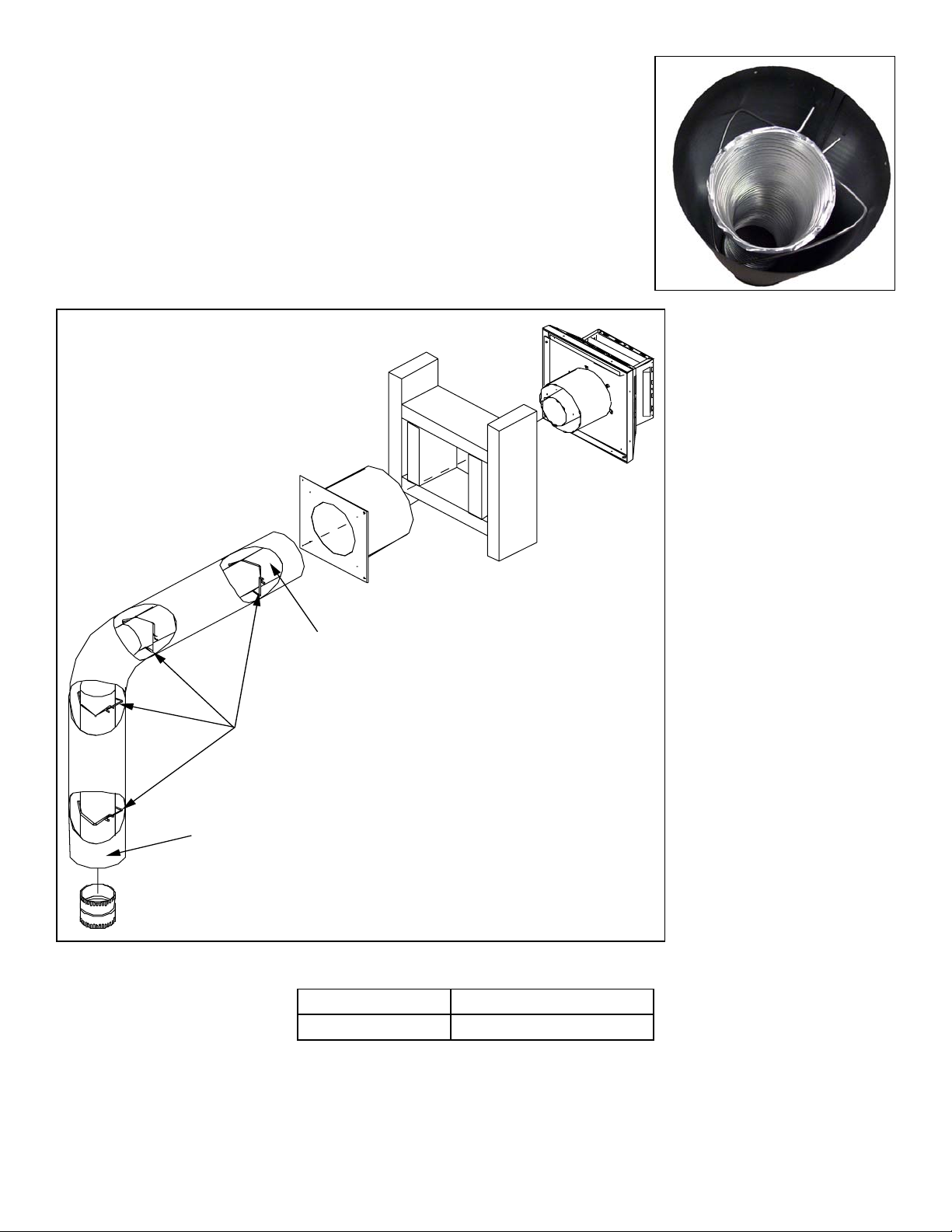
Figure 3
Wire Spacers
Horizontal Vent Termination
Wall Thimble
Fire Stop
Exhaust 4" Flex Pipe
Wall Framing
12. On the outside of the
exterior wall, apply a
bead of Mill-Pac Black
sealant to the Ø 4” (10
cm) pipe of the vent
terminal. Slide the
fl ex liner onto the vent
terminal and secure with
three (3) sheet metal
screws evenly spaced.
13. Place a bead of high
temperature silicone on
the intake collar of the
vent terminal, slide the
Ø6⅝” (16.25 cm) fl ex
intake liner over the
collar, secure the fl ex liner
with three (3) sheet metal
screws evenly spaced.
14. Attach the vent terminal
to the outside of the
house using four (4)
wood screws provided.
Combusion Air 6 5/8" Flex Pipe
Flue Pipe Adaptor
Figure 3
Part Number Option
50-1235
MANUFACTURED BY:
SHERWOOD INDUSTRIES LTD.
6782 OLDFIELD RD. SAANICHTON, BC, CANADA V8M 2A3
www.envirofi re.biz
Horizontal Vent Kit
April 13, 2005
C-10857
15. Light the appliance and
ensure proper operation.
 Loading...