

Page 1
WARRANTY REGISTRATION
WARRANTY REGISTRA TION
WARRANTY REGISTRA TION
enviro.com/warranty
enviro.com/warranty
enviro.com/warranty
E30I
GAS INSERT - LOG SET w/ IPI Valve
OWNER’S MANUAL
WARNING: If the information in this manual is not followed exactly,
a re or explosion may result causing property damage, personal
injury or loss of life. Installation and service must be performed by a
Report # 0268GN023S
CERTIFIED TO/ CERTIFIÉ AUX: ANSI Z21.88-2017 / CSA2.33-2017 VENTED GAS FIREPLACE HEATERS
Version Française: www.enviro.com/fr.html
qualied installer, service agency or the gas supplier.
50-2597
Page 2
Safety Precautions
WARNING:
FIRE OR EXPLOSION HAZARD
Failure to follow safety warnings exactly could result in serious
injury, death, or property damage.
- Do not store or use gasoline or other ammable vapors and
liquids in the vicinity of this or any other appliance.
- WHAT TO DO IF YOU SMELL GAS
• Do not try to light any appliance.
• Do not touch any electrical switch; do not use any phone in your
building.
• Leave the building immeadiately.
• Immeadiately call your gas supplier from a neighbor’s phone.
Follow the gas supplier’s instructions.
• If you cannot reach your gas supplier, call the re
department.
- Installation and service must be performed by a qualied
installer, service agency or the gas supplier.
INSTALLER:
Leave this manual with the appliance.
CONSUMER:
Retain this manual for future reference.
This appliance may be installed in an after-market permanently located,
manufactured (mobile) home, where not prohibited by local codes.
This appliance is only for use with the type of gas indicated on the rating plate. This
appliance is not convertible for use with other gases, unless a certied kit is used.
Massachusetts installations (Warning): This product must be installed by a licensed plumber or
gas tter when installed within the Commonwealth of Massachusetts. Other Massachusetts code
requirements: Flexible connector must not be longer than 36in., a shut o valve must be installed;
only direct vent sealed combustion products are approved for bedrooms/bathrooms. A carbon
monoxide detector is required in all rooms containing gas red direct vent appliances. The replace
damper must be removed or welded in the open position prior to installation of a replace insert.
2
Page 3
Safety Precautions
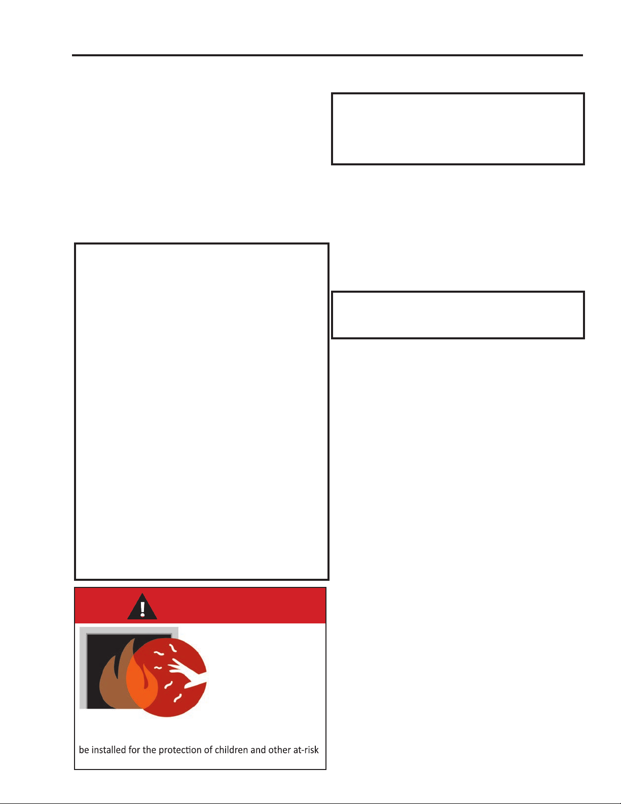
HOT GLASS WILL
CAUSE BURNS
DO NOT TOUCH GLASS
UNTIL COOLED.
NEVER ALLOW CHILDREN
TO TOUCH GLASS.
A barrier designed to reduce the risk of burns from the
hot viewing glass is provided with this appliance and shall
individuals.
FOR SAFE INSTALLATION AND OPERA TION OF YOUR “ENVIRO” HEA TER,
PLEASE CAREFULLY READ THE FOLLOWING INFORMATION:
• All ENVIRO gas-red appliances must be installed in
accordance with their instructions. Carefully read all the
instructions in this manual rst. Consult the building
authority having jurisdiction to determine the need for a
permit prior to commencing the installation.
• NOTE: Failure to follow these instructions could cause
a malfunction of the replace, which could result in death,
serious bodily injury, and/or property damage.
• Failure to follow these instructions may also void your
re insurance and/or warranty.
GENERAL
• Installation and repair should be done by a qualied
service person. The appliance should be inspected before
the rst use and, at least, annually by a qualied service
person. More frequent cleaning may be required due to
excessive lint from carpeting, bedding material, etc. It
is imperative the control compartments, burners and
circulating air passageways of the appliance be kept
clean.
• Due to high temperatures, the appliance should be
located out of high trac areas and away from furniture
and draperies.
Children and adults should be alerted to the
hazards of high surface temperatures and should
stay away to avoid burn or clothing ignition.
• Young children should be carefully supervised when
in the same room as the appliance. Toddlers, young
children and others may be susceptible to accidental
contact burns. A physical barrier is recommended if there
are at risk individuals in the house. T o restrict access to a
replace or stove install an adjustable safety gate to keep
toddlers, young children and other at risk individuals out of
the room and away from hot surfaces. Any safet y screen,
guard, or barrier removed for servicing an appliance must
be replaced prior to operating the appliance.
• Clothing or other ammable materials should not be
placed on or near the appliance.
• A barrier designed to reduce the risk of burns from the
hot veiwing glass is provided with this appliance and shall
be installed for the protection of children and other at-risk
individuals. If the barrier becomes damaged, the barrier
shall be replaced with the manufacturer’s barrier for this
appliance
FOR YOUR SAFETY
• Installation and service must be performed by a qualied
installer, service agency or gas supplier.
• This installation must conform to local codes or, in the
absence of local codes, with the National Fuel Gas Code,
ANSI Z223.1/NFPA 54, or the Natural Gas and Propane
Installation Code, CSA B149.1.
• To prevent injury, do not allow anyone who is unfamiliar
with the stove to operate it.
• To prevent injury, if the pilot or pilot and burners
have gone out on their own, open the glass door and
wait 5 minutes to air out before attempting to relight the stove.
• Always keep the area around these appliances clear of
combustible material, gasoline and other ammable liquids
and vapours.
• These appliances should not be used as a drying rack for
clothing or for hanging Christmas stockings/decorations.
• Due to the paint curing on the stove, a faint odor and slight
smoking will likely be noticed when the stove is rst used.
Open a window until the smoking stops.
Always connect this gas stove to a vent system and vent to
the outside of the building envelope. Never vent to another
room or inside the building. Make sure the specied vent
pipe is used, properly sized and of adequate height to
provide sucient draft. Inspect the venting system annually
for blockage and signs of deterioration.
WARNING: Failure to position the parts in accordance
with the diagrams in this booklet, or failure to use only
parts specically approved with this appliance, may result in
property damage or personal injury.
WARNING: Do not operate with the glass front removed,
cracked or broken. Replacement of the glass should be done
by a licensed or qualied service person.
• Never use solid fuels such as wood, paper, cardboard, coal,
or any ammable liquids, etc., in this appliance.
• Do not use this appliance if any part has been under water.
Immediately call a qualied service technician to inspect the
appliance and to replace any part of the control system or
any gas control which has been under water.
• Do not abuse the glass by striking it or slamming the door
shut.
• If the E30 unit is pulled out of its installation, and the ventair intake system is disconnected for any reason, ensure that
the vent-air intake pipes are reconnected and re-sealed in
accordance to the instructions noted in
- VentIng.
InItIal InstallatIon
3
Page 4

Table of Contents
Safety Precautions...........................................................................................................2
Table of Contents.............................................................................................................4
Codes And Approvals.......................................................................................................5
Specications..................................................................................................................6
Rating Label Location...........................................................................................6
Dimensions..........................................................................................................6
Install Depth........................................................................................................6
E33 Options Dimensions.......................................................................................7
Operating Instructions....................................................................................................8
Lighting and Turning O Instructions.....................................................................8
Venturi Adjustment...............................................................................................9
Normal Sounds During Operation.........................................................................9
Remote Control Operations..................................................................................9
System Description.............................................................................................10
Technical Data....................................................................................................10
Transmitter...................................................................................................10
Battery Holder .....................................................................................................11
Operating Procedure...........................................................................................12
Maintenance And Service................................................................................................16
Cleaning The Painted Surfaces............................................................................16
Glass Door Removal...........................................................................................16
Cleaning The Glass.............................................................................................16
Cleaning The Firebox..........................................................................................17
Replacing The Glass............................................................................................17
Check Pilot and Burner Flames............................................................................17
Removing Valve Cover.........................................................................................17
Fuel Conversion..................................................................................................18
Initial Installation...........................................................................................................20
Clearances to Combustibles.................................................................................20
Minimum Fireplace Size.......................................................................................20
Venting..............................................................................................20
Bae Plate Adjustment.......................................................................................22
Installing the Unit...............................................................................................23
Zero Clearance Fireplace Installation..................................................................25
Electrical Requirements.......................................................................................26
Gas Line Connection...........................................................................................27
Adjusting The Pilot Flame....................................................................................28
Secondary Installation....................................................................................................29
Safety Screen Installation / Remov al.....................................................................29
Optional Base Shelf & Riser ...................................................................................29
Optional Trimmable Panels..................................................................................30
Surround Panel Installation..................................................................................31
Firebox Liner and Burner T ube Remov al / Installation..............................................32
Log Set and Ember Removal / Installation..............................................................33
Troubleshooting............................................................................................................37
Parts List.......................................................................................................................40
Parts Diagram - Components..........................................................................................41
Notes.........................................................................................................................42
Warranty.......................................................................................................................43
Installation Data Sheet...................................................................................................44
4
Page 5
Codes And Approvals
DIRECT VENT: This type is identied by the sux DV. This appliance draws all of its air for combustion from
outside the dwelling, through a specially designed vent pipe system.
This appliance has been tested and approved for installations from 0 feet to 4500 feet (1372 m) abo ve sea level.
In the USA: The appliance may be installed at higher altitudes. Please refer to your American Gas Association
guidelines which state: the sea level rated input of Gas Designed Appliances installed at elevations above 2000
(610 m) feet is to be reduced 4% for each 1000 feet (305 m) above sea level. Refer also to local authorities
or codes which have jurisdiction in your area regarding the de-rate guidelines.
In Canada: When the appliance is installed at elevations above 4500 feet (1372 m), the certied high altitude
rating shall be reduced at the rate of 4% for each additional 1000 feet (305 m).
• This appliance has been tested by INTERTEK & OMNI-Test Laboratories and found to comply with the
established VENTED GAS FIREPLACE HEATER standards in CANADA and the USA as follows:
DIRECT VENTED GAS FIREPLACE INSERT HEATER
TESTED AND LISTED TO: ANSI Z21.88-2017/CSA 2.33-2017 VENTED GAS FIREPLACE HEATERS
CSA 2.17-2017 GAS FIRED APPLIANCES FOR HIGH ALTITUDES
CSA P.4.1-2015 TESTING METHOD FOR MEASURING ANNUAL FIREPLACE EFFICIENCY
This ENVIRO E30 Fireplace Insert:
• Has been certied for use with either natural or propane gases. (See rating label.)
• Is not for use with solid fuels.
• Is approved for bedroom or bed sitting room. (IN CANADA: must be installed with a permanent wall thermostat
for bedroom installations. Consult the authority having local jurisdiction in your area. IN USA: see current ANSI
Z223.1 for installation instructions.)
• Must be installed in accordance with local codes. If none exist, use current installation code CAN/CGA B149 in
Canada or ANSI Z223.1/NFPA 54 in the USA.
• Must be properly connected to an approved venting system and not connected to a chimney ue serving a
separate solid-fuel burning appliance.
• Is not approved for closet or recessed installations.
IMPORTANT NOTICE (Regarding rst re up): When the unit is turned on for
the rst time, it should be turned onto high without the fan on for the rst 4
hours. This will cure the paint, logs, gasket material and other products used in
the manufacturing process. It is advisable to open a window or door, as the unit
will start to smoke and can irritate some people. After the unit has gone through
the rst burn, turn the unit o, let the unit get cold then remove the glass door
and clean it with a good gas replace glass cleaner, available at your local ENVIRO
dealer. See “Door remoVal” and “CleanIng the glass” sections.
COLD CLIMATES:
NOTE: In cold climates, additional insulation may be used on some venting. It is
recommended in cold climates to wrap the exhaust and intake venting for the nal
few feet before termination.
5
Page 6
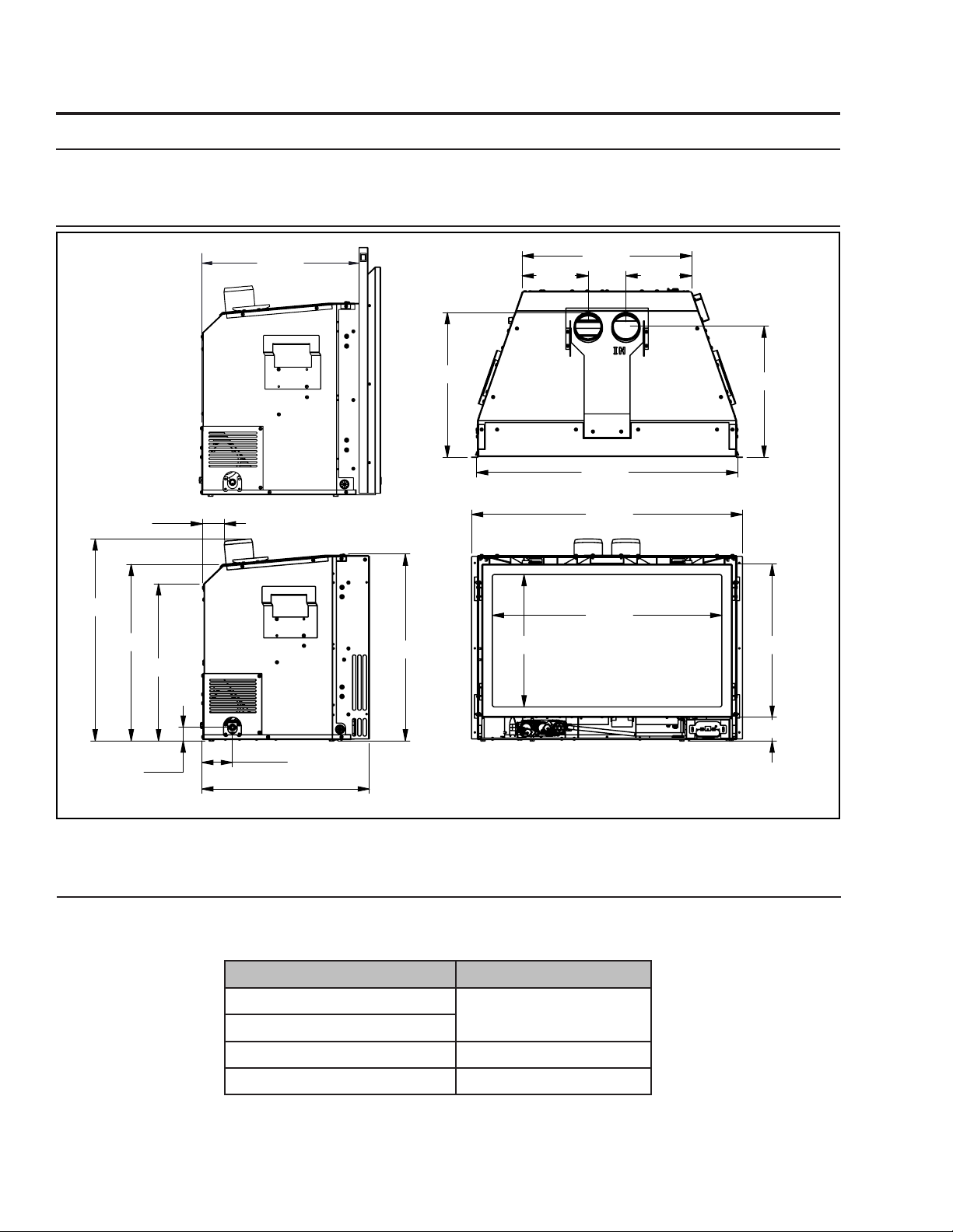
Specifications
19.000
Rating LabeL Location:
The rating label is located on the bottom of the unit, behind the front access door.
Dimensions:
*Shown with
Contemporary
surround
panel*
21.47
18.78
16.70
2.32
16.000
19.85
15.40
18.00
7.00 7.00
27.74
28.75
24.38
14.00
13.93
16.27
2.52
1.45
3.26
17.79
Figure 1: E30 Exterior Dimensions.
instaLL Depth:
The install depth will vary depending on what surround panel is used. Table 1 shows the required depth
for each surround panel.
Surround Panel Required Depth
Contemporary
16” [406 mm]
Extruded
Modern 16 ⅞” [429 mm]
Slim & Elite Panels 17 ¼” [438 mm]
Table 1: Install Depths
6
Page 7
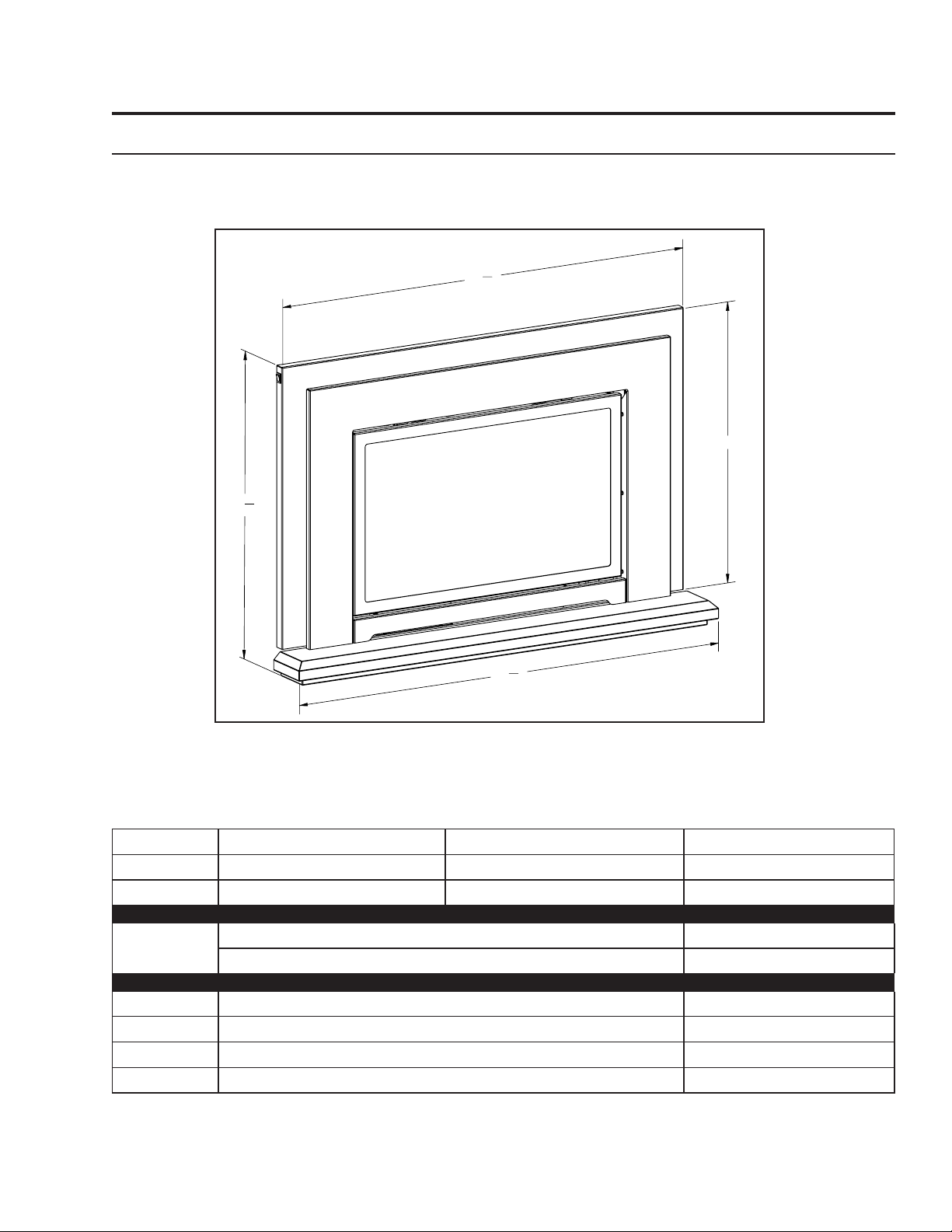
e30 options Dimensions:
3
27
"
8
Specifications
5
39
"
8
25"
5
41
"
8
Figure 2: E30 Contemporary Surround with Base Shelf and Riser.
Table 2: E30 Options Dimensions.
Regular Surround Contemporary Surround Extruded Surround
Height 25” (635mm) 25” (635mm) 25” (635mm)
7
Width 39
Trimmable
Surround
/8” (1013 mm) 39 7/8” (1013 mm) 39 7/8” (1013 mm)
Height Width
38” (965mm) 46” (1168mm)
Base Shelf Base Shelf Riser
Height 1 ⅝” (41mm) 2 ⅛” (54mm)
Width 41
Depth Bottom 4 ⅞” (112mm); Top 3
5
/8” (1057mm) 40 1/4” (1022mm)
13
/16” (97mm) 3 11/16” (94mm)
7
Page 8
Operating Instructions
For Your Safety, Read Safety Precautions And Lighting Instructions Before Operating
WARNING: IF YOU DO NOT FOLLOW THESE INSTRUCTIONS EXACTLY A FIRE OR EXPLOSION
MAY RESULT, CAUSING PROPERTY DAMAGE, PERSONAL INJURY OR LOSS OF LIFE.
Lighting anD tuRning off instRuctions:
FOR YOUR SAFETY READ BEFORE OPERATING
WARNING:IF YOU DO NOT FOLLOW THESE INSTRUCTIONS EXACTLY, A FIRE OR EXPLOSION
MAY RESULT CAUSING PROPERTY DAMAGE, PERSONAL INJURY OR LOSS OF LIFE.
A. This appliance is equipped with an ignition device
which automatically lights the pilot. Do not try to
light the pilot by hand.
B. BEFORE OPERATING smell all around the
appliance area for gas. Be sure to smell next to the
floor because some gas is heavier than air and will
settle on the floor.
WHAT TO DO IF YOU SMELL GAS:
Do not try to light any appliance.
Do not touch any electrical switch; do not use any
phone in your building.
Immediately call your gas supplier from a
neighbor’s phone. Follow the gas supplier’s
instructions.
If you cannot reach your gas supplier, call the
fire department.
OPERATING INSTRUCTIONS
C. Use only your hand to push in or
turn the gas control knob. Never
use tools. If the knob will not push
in or turn by hand, don’t try to
repair it, call a qualified service
technician. Force or attempted
repair may result in a fire or
explosion.
D. Do not use this appliance if any
part has been under water.
Immediately call a qualified service
technician to inspect the appliance
and to replace any part of the
control system and any gas control
which has been under water.
1. STOP! Read the safety information above on this label.
2. Read the owner's manual including the section on
"Remote Control" operation.
3. Set the thermostat to the lowest setting.
4. Turn off all electric power to the appliance.
5. Do not attempt to light the pilot by hand.
6. Wait five (5) minutes to clear out any gas. Then smell for
gas, including near the floor. If you smell gas, STOP!
Follow "B" in the safety information above on this label.
If you don't smell gas, go to the next step.
7. Turn on all electric power to the appliance.
8. Using the remote control, set
thermostat to desired setting, or
press the ON/OFF key on the
remote. "ON" will be indicated on the
display of the remote and an audible
"beep" will be heard at the unit to
indicate the command has been
received.
9. This appliance is equipped with a
completely automatic ignition and
lighting control. The control will
attempt to light the pilot several
times if necessary. If it is
unsuccessful, it will discontinue
operations. If the appliance will
not operate, follow the
instructions "To Turn Off Gas To
Appliance" and call your service
technician or gas supplier.
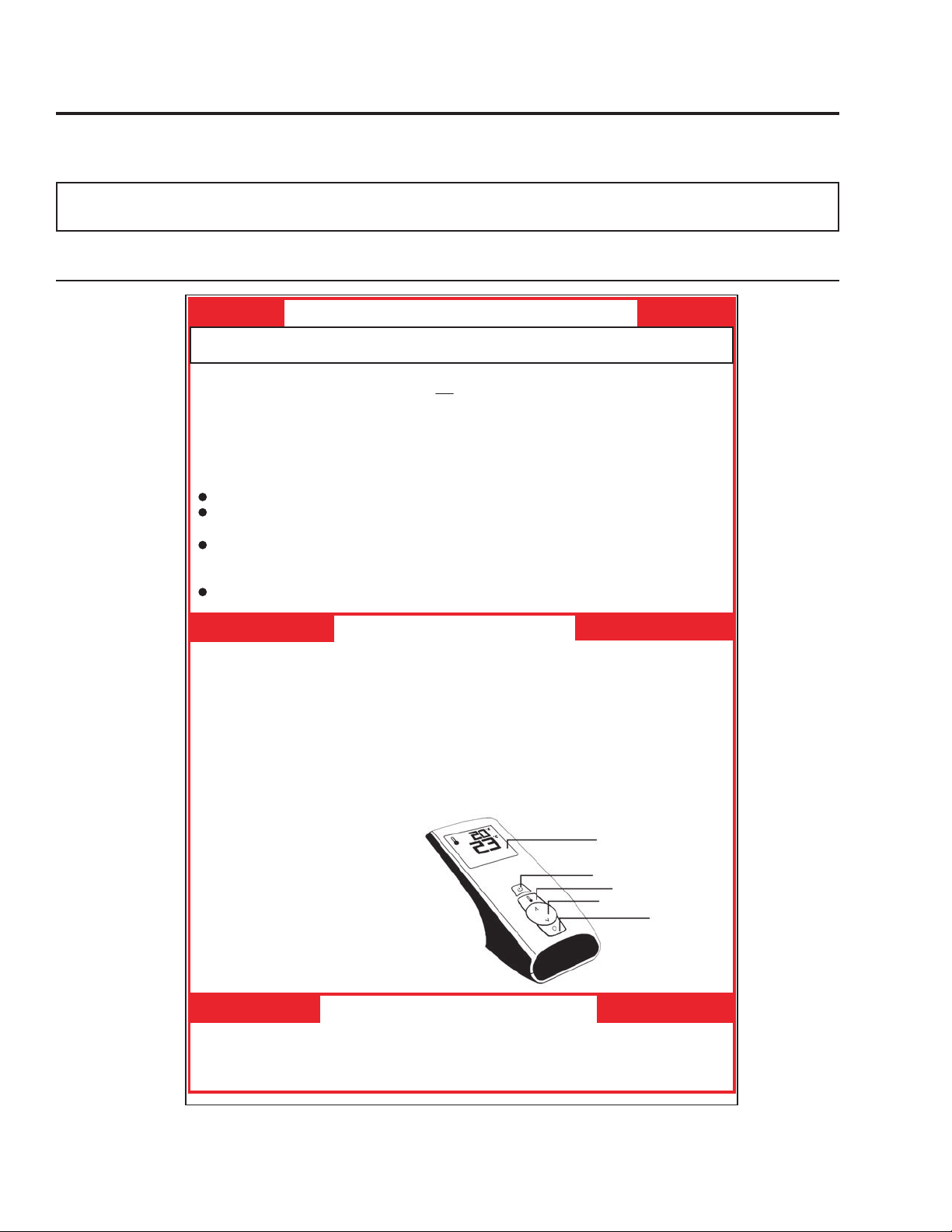
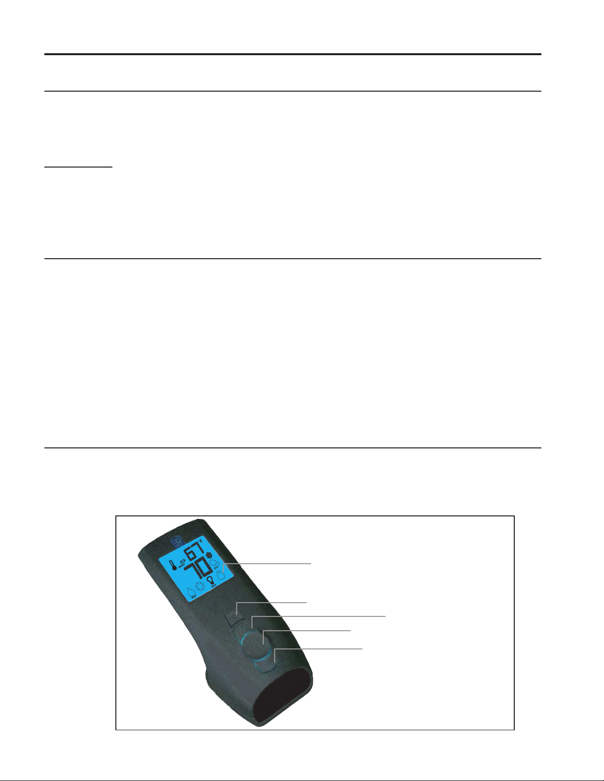
Blue LCD Display
ON/OFF Key
THERMOSTAT Key
UP/DOWN Arrow Key
MODE Key
TO TURN OFF GAS TO APPLIANCE
1. Set thermostat to lowest setting, or press the ON/OFF Key. "OFF" will be indicated on the display
and an audible "Beep" will be heard at the unit to indicate the command has been received.
2. Turn off all electric power to the appliance if service is to be performed.
C-12455
Figure 3: Lighting instruction label.
8
Page 9
Operating Instructions
VentuRi aDjustment:
The venturi adjustment lever is located on the right side of the unit, below the door (see Figure 4). To
avoid touching hot surfaces under the unit, use the Door Tool to adjust the venturi.
The venturi allows the amount of air coming into the replace to be adjusted in order to accommodate
dierent climates and venting arrangements. Start the pilot and then the burner. Make sure the pilot
ame is burning normally and none of the burner ports are plugged. Let the replace burn for roughly
fteen (15) minutes and then examine the ames. The
ideal ame will be blue at the base and light orange
above. The ames should be of medium height. If the
ames look like this, no venturi adjustment is needed. If
the ames are fairly short and mostly blue, the replace
is getting too much air. Therefore, the air shutter should
be closed (push in) slightly until the correct ames are
achieved. Flames that are very orange, with tall dark
stringy tips are not getting enough air. Open (pull out)
the venturi until the ames clean up. If the venturi is
Figure 4: Adjusting the venturi air setting.
Warning: Incorrect venturi adjustment may lead to improper combustion, which is a safety hazard.
Contact the dealer if there is any concern about the venturi adjustment.
opened, then closed all the way, and the correct ames
cannot be attained, turn o the gas and contact the
dealer.
Component Sound & Reason
Fire Box Creaking when heating up or cooling down.
Burner Light pop or poof when turned o; this is more common with LP units.
Pilot Flame Quiet whisper while the pilot ame in on.
Blower / Fan Air movement that increases and decreases with the speed of the blower.
Gas Control Valve Dull click when turning on or o, this is the valve opening and closing.
IFC Beeps when remote control/transmitter buttons are pressed.
Table 3: Normal Sounds
Remote contRoL opeRations:
The Proame 2 GTMFLSA is a modular remote control system that directs the functions of the E30.
The Proame 2 GTMFLSA is congured to control the on/o main burner operation, its ame levels and
provides on/o and Smart thermostatic control of the appliance.
9
Page 10
Operating Instructions
Blue LCD display
UP/DOWN Arrow Key
ON/OFF Key
THERMOSTAT Key
MODE Key
system DescRiption:
The Proame 2 Remote Control System consists of two (2) elements:
1. Proame 2 Transmitter.
2. Integrated Fireplace Controller (IFC) and wiring harness to connect to the gas valve, stepper motor
battery holder, and convection fan.
ATTENTION!
- TURN “OFF” THE MAIN GAS SUPPLY OF THE APPLIANCE DURING INSTALLATION OR
MAINTENANCE OF THE IFC.
- TURN “OFF” MAIN GAS SUPPLY TO THE APPLIANCE PRIOR TO REMOVING OR REINSERTING
THE BATTERIES IN THE BATTERY HOLDER
technicaL Data
Transmitter (Remote Control):
Supply voltage: 4.5 V (three 1.5 V AAA batteries)
Radio frequency: 315 MHz
Integrated Fireplace Controller (IFC):
Supply voltage: AC IN - 120 V / 60 Hz
Battery Backup IN - 6 Vdc - 200mA (four 1.5 V AA batteries)
Spark voltage / frequency: >10kV / 1Hz
Comfort modulating fan: 120 V / 60 Hz / 2A
Auxiliary: 120 V / 60 Hz / 5A
tRansmitteR:
The Proame 2 Transmitter is a remote control with a blue backlit lcd display. It uses a streamline design with
a simple button layout and informative lcd readout (Figure 5). The Transmitter is powered by three (3) AAA
type batteries. A Mode Key is provided to Index between the features and a Thermostat Key is used to turn
on/o or index through Thermostat functions (Figure 5 & 6).
10
Figure 5: Proame 2 Transmitter.
Page 11
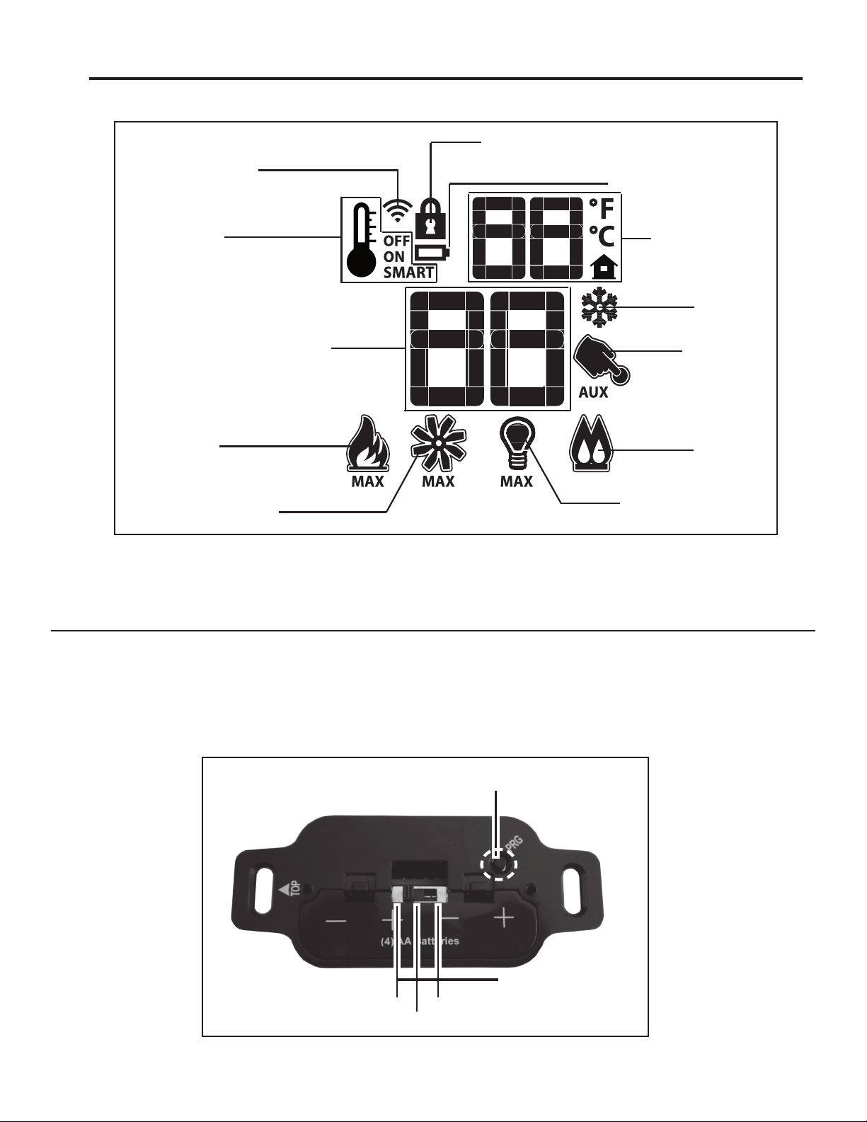
Low battery alarm
Key Lock
Room
Temperature
Dimmer ON
Set Point
Temperature/Level/State
Flame ON
Thermostat OFF/
ON/SMART
Comfort fan
Transmission
Split Flow
Aux ON
CPI mode
Operating Instructions
ot used]
[N
[Not used]
[Not used]
Figure 6: Proame 2 Transmitter LCD Screen.
batteRy hoLDeR:
The Battery Holder (Figure 7) connects directly to the IFC with a wiring harness. The IFC is powered by four (4)
AA type batteries. The IFC accepts commands via radio frequency from the Transmitter to operate the appliance in
accordance with the particular Proame system conguration. The Battery Holder has a three (3) position slider switch
that can be set to one of three positions: ON (Manual Override), Remote (Remote control), or O. The Battery Holder
has a reset button at the front right corner that is used is to synchronize the Transmitter when using the for the rst
time, or after the batteries have been replaced.
Reset Button
ON
OFF
REMOTE
Figure 7: Battery Holder.
3 Position Slider
11
Page 12

Operating Instructions
Room Temperature
Set Temperature
Thermostat ON
opeRating pRoceDuRe:
Initializing The System For The First Time
Install the four (4) AA batteries into the IFC battery holder. Note the polarity of the battery and insert into the battery
bay as indicated on the body of the battery holder. Press and release the reset button (see Figure 7).
The IFC will “beep” three (3) times to indicate that it is ready to synchronize with a Transmitter. Install the three (3)
AAA type batteries in the Transmitter battery bay, located on the base of the Tr ansmit ter. With the batteries already
installed in the T ransmitter , push the ‘ON’ button. The IFC
will “beep” four (4) times to indicate the Transmitter’s
command is accepted and sets to the particular code of
that Transmitter. The system is now initialized.
Temperature Indication Display
With the system in the “OFF” position, press the
Thermostat Key and the Mode Key at the same time.
Look at the LCD screen on the transmitter to verify that
a °C or °F is visible to the right of the Room Temperature
display (see Figure 8).
Turn on the Appliance
Press the ON/OFF Key on the Transmitter. The Transmitter display will show all active Icons on the screen. A single
“beep” from the IFC will conrm reception of the command and will commence to rst ignite the pilot light, followed
by the main burner. This should take about 10 seconds to complete.
Figure 8: Remote Control Display in Farenheit and Celcius.
Turn o the Appliance
Press the ON/OFF Key on the Transmitter. The Transmitter LCD display
will only show the room temperature and Icon (see Figure 9). A single
“beep” from the IFC conrms reception of the command and both the
pilot light (if the unit is not set to continuous pilot) and main burner will
turn o.
Room Thermostat (Transmitter Operation)
The Remote Control can operate as a room thermostat. The thermostat
can be set to a desired temperature to control the comfort level in a
room. To activate this function, press the Thermostat Key (see Figure
5). The LCD display on the Transmitter will change to show that the
room thermostat is “ON” and the set temperature is now displayed (see
Figure 9). To adjust the set temperature, press the Up or Down Arrow
Keys until the desired set temperature is displayed on the LCD screen
of the Transmitter.
Smart Thermostat (Transmitter Operation)
The Smart Thermostat function adjusts the ame height in
accordance to the dierence between the set point temperature
and the actual room temperatures. As the room temperature
gets closer to the set point the Smart Function will modulate
the ame down. To activate this function, press the Thermostat
Key (Figure 5) until the word “SMART” appears to the right
of the temperature bulb graphic (Figure 10). To adjust the
set temperature, press the Up or Down Arrow Keys until the
desired set temperature is displayed on the LCD screen of the
Transmitter.
Figure 9: Remote Control Displays
Set Temperature.
Figure 10: Remote Control’s Smart Flame Function.
12
Page 13
Operating Instructions
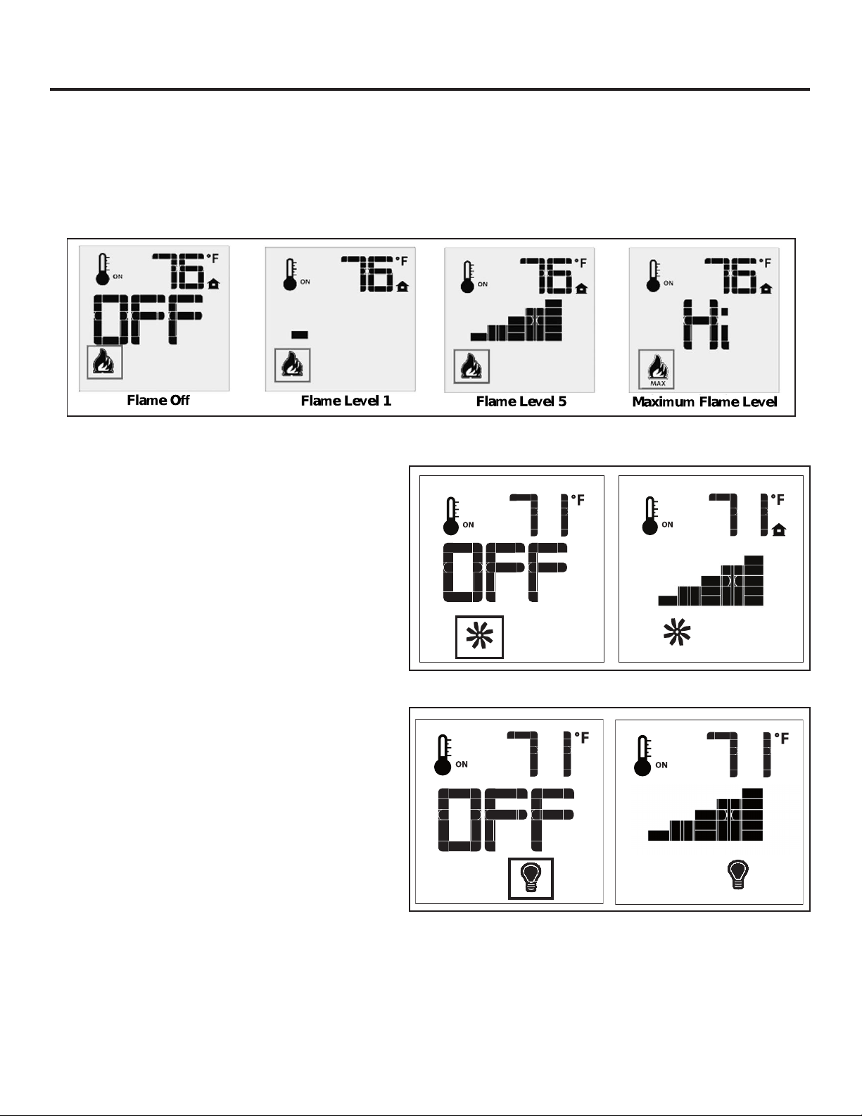
Flame Off
Flame Level 1
Flame Level 5
Maximum Flame Level
Flame Off
Flame Level 1
Remote Flame Control
The Proame 2 GTMF has six (6) ame levels. With the system on, and the ame level at the maximum in the
appliance, pressing the Down Arrow Key once will reduce the ame height by one step until the ame is turned o.
The Up Arrow Key will increase the ame height each time it is pressed. If the Up Arrow Key is pressed while the
system is on but the ame is o, the ame will come on in the high position (refer to Figure 11 below). A single “beep”
will conrm reception of the command.
Figure 11: Remote Control’s Flame Levels.
Fan Control
The E30 comes with a convection fan that can be
controlled with the Transmitter. The fan speed can be
adjusted thorugh six (6) speeds. To control the fan
press the MODE key (Figure 5) to index to the fan
control icon (Figure 12). Use the UP/DOWN arrow
keys to turn on, o, or adjust the fan speed (Figure
12). A single beep from the IFC will conrm the
command has been received
Light Control
This function is not used on the E30 and can be
disregarded.
Figure 12: Fan Control
Figure 13: Light Control
13
Page 14
Operating Instructions
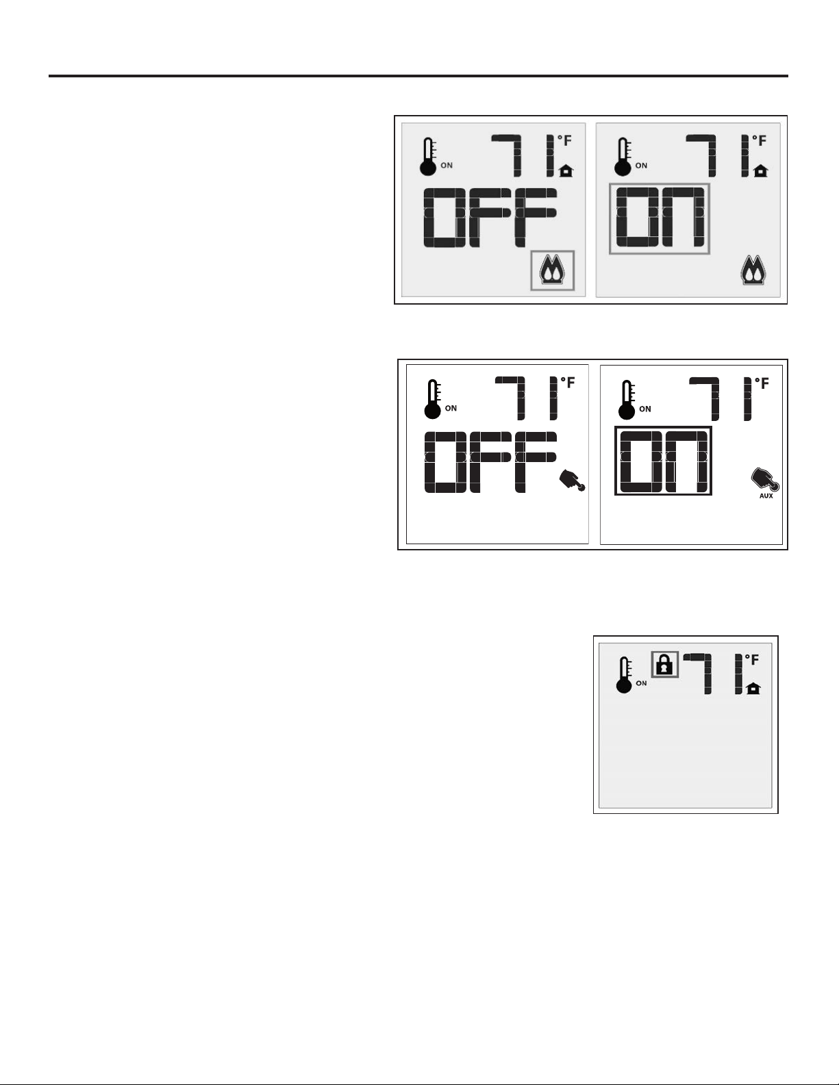
Split Flow Control
This function is not used on the E30 and can be
disregarded.
Aux Control
This function is not used on the E30 and can be
disregarded.
Figure 14: Split Flow Control
Figure 15: Aux Control
Key lock
This function will lock the keys to avoid unsupervised operation. To activate this
function, press the MODE and UP keys at the same time and the a lock will appear
(see Figure 16). To de-activate this function, press the MODE and UP Keys at the
same time.
Figure 16: Remote Control
Locked.
14
Page 15

Operating Instructions
Low Battery Power Detection
T ransmitter: The life span of the remote control bat teries depends on various factors:
quality of the batteries used, the number of ignitions of the appliance, the number of
changes to the room thermostat set point, etc. When the Transmitter batteries are
low, a Battery Icon will appear on the LCD display of the Transmitter (see Figure
17) before all battery power is lost. When the batteries are replaced this Icon will
disappear.
IFC: The life span of the IFC batteries depends on various factors during a prolonged
power outage: quality of the batteries used, the number of ignitions of the appliance,
the number of changes to the room thermostat set point etc. When the IFC batteries
are low, No “beep” will be emitted when it receives an On/O command from
the Transmitter. This is an alert for a low battery condition for the IFC. When the
batteries are replaced the “beep” will be emitted from the IFC when the ON/OFF Key
is pressed (See
Switching to Continuous Pilot Mode
When the replace is turned o press the mode
key to index to the constant pilot (CPI) mode icon
(see gure 6). Pressing the up arrow key will select
Continuous Pilot Ignition (CPI) and pressing the down
arrow key will return to IPI. Once a selection is made
the IFC will beep once to conrm it had received the
command. NOTE: It is recommended to use the
continuous pilot mode during the winter when
the outside temperature is below 50°F (10°C)
to keep the chimney properly heated for updraft
during burner ignition. Continuous pilot mode also
keeps the rebox warm which eliminates both heat
loss to cold air that is trapped inside the rebox as
well as excessive exhaust vapour condensation on
the door glass.
InItIalIzIng the system for the fIrst tIme).
Figure 18: CPI Pilot Mode
Figure 17: Low Battery
Indicator.
WARNING: Fire Hazard. Can cause severe injury or death. The IFC causes ignition of the appliance.
The appliance can turn on suddenly. Keep away from the appliance burner when operating the remote
system.
WARNING: Shock Hazard. Can cause severe injury or death. This device is powered by line voltage. Do
not try to repair this device. In no way is the enclosure to be tampered with or opened. Disconnect from
line voltage before performing any maintenance.
CAUTION: Property Damage Hazard. Excessive heat can cause property damage. The appliance can stay
lit for many hours. Turn o the appliance if it is not going to be attended for any length of time. Always
place the Transmitter where children cannot reach it.
15
Page 16

Maintenance And Service
Warning: Failure to position the parts in accordance with this manual, or failure to use only parts
specically approved with this appliance, may result in property damage or personal injury.
At least once a year, run through the following procedures to ensure the system is clean and working
properly . Check the burner to see if all the ports are clear and clean. Check the pilot to mak e sure it is not
blocked by anything. The pilot ame should be blue with little or no yellow on the tips.
The venting system must be periodically examined; it is recommended the examination is done by a
qualied person.
cLeaning the painteD suRfaces:
Painted surfaces should be periodically wiped with a damp cloth when the unit is cool.
gLass DooR RemoVaL:
Figure 19: Door Release.
Remove the glass door by placing the hooked end of the door release tool in the hole on the door latch
mechanism (see Figure 19) and pulling the latch out then over to the center of the unit. When the two
(2) latches have been released, tilt the door forward and then lift up to unhook the bottom door tabs (see
Figure 20). Re-assemble in the reverse order.
Warning: Do not touch or attempt to remove the glass if the replace is not completely cool.
Never operate the replace with the glass removed.
CAUTION GLASS MAY SEPARATE FROM DOOR.
Figure 20: Door Removal.
cLeaning the gLass:
When the replace is cool, remove the glass door as instructed above. Check the gasket material on
the back of the glass, making sure that it is attached and intact.
During a cold start up, condensation will form on the glass. This is a normal condition with all replaces.
However, this condensation can allow dust and lint to cling to the glass surface. Initial paint curing of the
appliance can leave a slight lm on the glass. The glass will need cleaning after the replace has cooled
o from the rst burn and about two weeks after rst burn. Use a mild glass cleaner and a soft
cloth. Abrasive cleaners will damage the glass and painted surfaces. Depending on the amount
of use, the glass should require cleaning no more than two or three times a season. Do not clean the
glass when it is hot.
16
Page 17

Maintenance And Service
cLeaning the fiRebox:
Remove the logs carefully, as they are very fragile. Gently remove all the embers and rock wool and
place on a paper towel. Vacuum the bottom of the rebox thoroughly. Carefully clean any dust o the
logs and remove any lint from the burner and pilot. At this time, inspect the burner tube for cracking or
severe warping. If a problem is suspected, contact the dealer. Check the logs for deterioration or large
amounts of soot; a small amount on the logs is normal. Replace the logs and embers as in the seConDary
InstallatIon - log set anD ember InstallatIon section. If new/more embers and rock wool are required,
contact your nearest ENVIRO dealer.
RepLacing the gLass:
The glass in the replace is a high temperature ceramic. If the glass is damaged in any way, a factory
replacement is required (see Parts lIst). Wear gloves when handling damaged glass door assembly
to prevent personal injury. Do not operate with the glass front removed, cracked or broken. Removal
and replacement of the glass from the door must be done by a licensed or qualied service person.
The glass must be purchased from an ENVIRO dealer. No substitute materials are allowed.
Remove the door (see page 16). The replacement glass will come with a new gasket installed. Remove
any silicone remnants from the door. Apply high temperature silicone to the two vertical faces of the
door and install the new piece of glass with gasket (be sure to maintain edge clearances). Apply even
pressure to the glass to allow the silicone to adhere to the gasket material.
check piLot anD buRneR fLames:
Periodically do a visual check of the pilot ames. One ame should encompass the ame sensor (see
page 28) and the other should burn over the burner ports. Also check that the burner is operating
correctly, refer to Venturi Adjustment section.
RemoVing VaLVe coVeR:
The valve cover can be removed to access
the gas valve.
1. Remove the glass door as shown in
maIntenanCe anD serVICe - glass Door
remoVal.
2. Remove the log set and ember material.
Refer to seConDary InstallatIon - log
set anD ember InstallatIon.
3. Remove the front brick liner and the
burner tube. Refer to seConDary
InstallatIon - fIrebox lIner anD burner
tube remoVal.
4. Use a T-20 screwdriver to remove the
two screws that hold down the left
burner support.
5. Then remove the six screws that hold
the valve cover in place (pointed out in
Figure 21).
Valve
Cover
Left Burner
Support
Figure 21: Valve Cover and Burner Support.
17
Page 18

Maintenance And Service
fueL conVeRsion:
TO BE INSTALLED BY A QUALIFIED SERVICE AGENCY ONLY
Please read and understand these instructions before installing.
Warning: This conversion kit shall be installed by a qualied service agency in accordance
with the manufacturer’s instructions and all applicable codes and requirements of the
authority having jurisdiction. If the information in these instructions is not followed
exactly, a re, explosion or production of carbon monoxide may result causing property
damage, personal injury or loss of life. The qualied service agency is responsible for
the proper installation of this kit. The installation is not proper or complete until the
operation of the converted appliance is checked as specied in the manufacturer’s
instructions supplied with the kit.
Kit Parts List for all E30I models:
1 - Orice (NG: #37) or (LP: #52) 1 - Servo Regulator with diaphragm
1 - Installation instruction sheet 2 - Conversion labels
Carefully inspect all parts supplied with this conversion kit. If any parts have been damaged or are
missing, contact your dealer, distributor or courier company to have them replaced before starting this
installation.
Conversion Kit Installation:
1. Turn the unit o by pressing the ON/OFF Key on the remote and shut o gas supply at the shut-o
valve upstream of the unit. CAUTION: The gas supply must be shut o prior to disconnecting the
electrical power and before proceeding with the conversion. Allow the valve and unit to cool down
to room temperature.
2. Remove the glass door as shown in the maIntenanCe anD serVICe - glass Door remoVal.
3. Carefully remove the log set.
4. Remove the burner as shown in
maIntenanCe anD serVICe - burner remoVal.
5. Convert the pilot injector (see Figure 22):
a) Using a 7/16” wrench, turn the pilot head a
1/4 turn counter-clockwise
b) Push the slider with your nger or at head screwdriver
- Natural Gas is marked NAT.
- Propane gas is marked LP with an indicating hole
between L and P. It is also marked red.
c) Turn the pilot head a 1/4 turn clockwise
back to its original position.
Figure 22. Pilot Slider set to LP
6. Convert the burner orice:
a) Remove the main burner orice with a 3/8” deep socket
b) Put a bead of pipe-thread sealant into the orice mount. DO NOT OVER-TIGHTEN
c) Install new orice.
18
Page 19

Maintenance And Service
7. Convert the SIT gas valve:
a) Use a T-20 driver to remove the two screws that hold the servo regulator to the gas valve and
disconnect the wire harness from the IFC.
b) Remove the rubber regulator diaphragm that is situated between the servo regulator and the valve
body. The new servo regulator already has this diaphragm installed.
c) Install the LP servo regulator, with the new longer T-20 screws included in the kit and connect the
harness to the IFC.
8. R einstall the burner , log set, and glass door. Also refer to seConDary InstallatIon - log set InstallatIon
in your Owner’s Manual. When re-installing the burner, ensure that the burner to pilot hood and
shield relationship is similar to what is shown in Figure 23.
9. Reconnect the main gas line if it was disconnected and open the shut-o valve at the gas line to the
unit.
10. Reconnect the electrical power to the unit.
11. Use a small brush to apply a warm soapy water
solution to all gas connections (use a half dish soap
and half warm water). If a gas leak is present,
bubbling will occur. Gas leaks can be repaired by
using an approved pipe thread sealant or approved
Teon tape. NEVER USE AN OPEN FLAME WHEN
TESTING FOR LEAKS.
12. Relight the pilot and conrm the ame properly
covers the ame sensor (see page 28). Should
the pilot require adjustment, turn the adjustment
screw (see page 28) clockwise to decrease or
counterclockwise to increase until the correct
ame is achieved.
13. Relight the main burner in both the “MAX” and low positions to verif y proper burner ignition, operation
and proper ame appearance (gure 62, page 36). Conrm the inlet and manifold pressures are
within the acceptable ranges as directed in section
testIng. If the E30 has been installed at an altitude higher than 2000ft (610m) it is required to
de-rate the unit accordingly:
In the USA: The appliance may be installed at higher altitudes. Please refer to your American Gas
Association guidelines which state: the sea level rated input of Gas Designed Appliances installed at
elevations above 2000 (610 m) feet is to be reduced 4% for each 1000 feet (305 m) above sea level.
Refer also to local authorities or codes which have jurisdiction in your area regarding the de-rate
guidelines.
In Canada: When the appliance is installed at elevations above 4500 feet (1372 m), the certied high
altitude rating shall be reduced at the rate of 4% for each additional 1000 feet (305 m).
14. MAKE SURE that the conv ersion label is installed on or close to the rating label to signif y that the unit
has been converted to a dierent fuel type.
IntIal IntallatIon - gas lIne ConneCtIon anD
Figure 23. Correct Pilot
19
Page 20

Initial Installation
37”
36”
35”
34”
33”
32”
31”
30”
1 2 3 4 5 6 7 8 9 10 11 12
MANTLE HEIGHT
(FROM UNIT BOTTOM)
MANTLE DEPTH
Minimum Mantle Clearances
12” MANTLE
WARNING: Operation of this heater when not connected to a properly installed and maintained
venting system can result in carbon monoxide (CO) poisoning and possible death.
cLeaRances to combustibLes:
Maintain sucient clearances for operation, service
and maintenance.
• A minimum distance of 21” (533 mm) is required
from the centerline of the unit to the sidewalls.
• Minimum clearance for any combustible facing is 30”
(762 mm) from the bottom of the unit.
• A 12” (305 mm) wide mantel can be mounted at a
minimum height of 36” (914 mm) from the bottom
of unit.
• No oor protection is required for any install height.
However it is still recommended to use 12” of
oor protection especially when carpet or linoleom
ooring are used infront of the insert.
• Unit can be installed with combustible material
underneath, as long as it is raised 2 ¼” o the oor.
• Minimum ceiling clearance is 54” from bottom of
unit.
Figure 24: Mantle width and height.
minimum fiRepLace size:
Table 4: Minimum dimensions of replace for E30 to be installed into.
Width At Front Width At Back Height Depth
1
Fireplace Dimensions 28” (711 mm) 18
/2” (470 mm) 20” (508 mm) 16” (406 mm)
NOTE: Space must be provided for gas line on left side of unit for servicing purposes. The E30 can only
be installed into masonary or zero-clearance replaces.
Venting:
WARNING: This appliance has been designed to draw room air for proper heat circulation
from the sides and bottom of the unit, and out the top front. Blocking or modifying these
openings in any way can create hazardous situations.
The vent length for the E30 must be between 8ft (2.44 m) and 30ft (9.14 m).
This model is vented with a 3” intake and a 3” exhaust aluminum or stainless steel ex vent leading into
a vertical termination cap. The ue collars of this model will t inside of a standard 3” vent and must be
fastened directly to the vent with three screws.. The exhaust vent and air intake are both located on the
top of the unit.
Check periodically that the vents are unrestricted. Also ensure that all direct vent pipes have been
properly sealed and installed after routine inspection or cleaning. The air intake and exhaust pipes must
be installed in the correct locations on the top of the E30.
20
Page 21

Initial Installation
QUALIFIED INSTALLERS ONLY
The ENVIRO E30 may be installed and vented into any solid fuel replace that has been installed in
accordance with the National, Provincial/State and local building codes and has been constructed of noncombustible materials. Before starting, refer to please reference the information in Table 5 and Figures
25 and 26.
An approved chimney liner and rain cap must be used. A throat connector or ashing must be installed to
ensure a tight seal, top performance, safety and eciency. Carefully follow the manufacturer’s instructions
that accompany the chimney liner kit. Use double walled aluminum ex vent from either M&G DuraVent
DirectVent Pro or ICC Excel Direct (see table 6). If necessary, remove the vent collar plate from the top
of the insert and connect it securely to the liner with sheet metal screws.
Check for any tears in the liner at this point. IMPORTANT : The screws that hold the vent collar plate in its
approved position must be installed.
NOTE: If the E30 unit is pulled out of its installation, and the vent air intake system is disconnected
for any reason, ensure that the vent-air intake pipes are re-sealed with high-temperature sealant and
reconnected with three (3) sheet metal screws evenly spaced.
The height for the vent must be between 8 ft (2.44 m) and 30 ft (9.14 m).
Install a sealed vent cap to prevent leakage of room air up through chimney .
The intake and the exhaust are 3" (76mm).
Measure the height of the chimney beforehand and purchase the appropriate
venting. Never attempt to over-stretch a flexible liner to accommodate the
height of the chimney . Every joint in the venting must be secured with three (3)
#8 x 3/8” HWH sheet metal screws and an appropriate sealant (either silicone
or stove cement).
The flue damper can be fully blocked open or removed for installation of the
unit; the smoke shelves, shields and baffles may be removed if attached by
mechanical fasteners.
The fireplace and fireplace chimney must be clean, in good working order and
constructed of non-combustible materials.
Make sure that all chimney cleanouts are tight fitting and will not permit air to
leak into the chimney .
Refractory, glass doors, screen rails, screen mesh and log grates can be
removed from the fireplace before installing the unit.
Figure 25: Installation of E30
21
Page 22

Initial Installation
The height for the vent must be between 8 ft (2.44 m) and 30 ft (9.14 m).
Install a sealed vent cap to prevent leakage of room air up through chimney .
The intake and the exhaust are 3" (76mm).
Measure the height of the chimney beforehand and purchase the appropriate
venting. Never attempt to over-stretch a flexible liner to accommodate the
height of the chimney . Every joint in the venting must be secured with three (3)
#8 x 3/8” HWH sheet metal screws and an appropriate sealant (either silicone
or stove cement).
The flue damper can be fully blocked open or removed for installation of the
unit; the smoke shelves, shields and baffles may be removed if attached by
mechanical fasteners.
The fireplace and fireplace chimney must be clean, in good working order and
constructed of non-combustible materials.
Make sure that all chimney cleanouts are tight fitting and will not permit air to
leak into the chimney .
Refractory, glass doors, screen rails, screen mesh and log grates can be
removed from the fireplace before installing the unit.
QUALIFIED INSTALLERS ONLY
The height for the vent must be between 8 ft (2.44 m) and 30 ft (9.14 m).
Install a sealed vent cap to prevent leakage of room air up through chimney .
The intake and the exhaust are 3" (76mm).
12”
*This installaon is not tested and is not covered by the cercaon of this appliance. Please contact
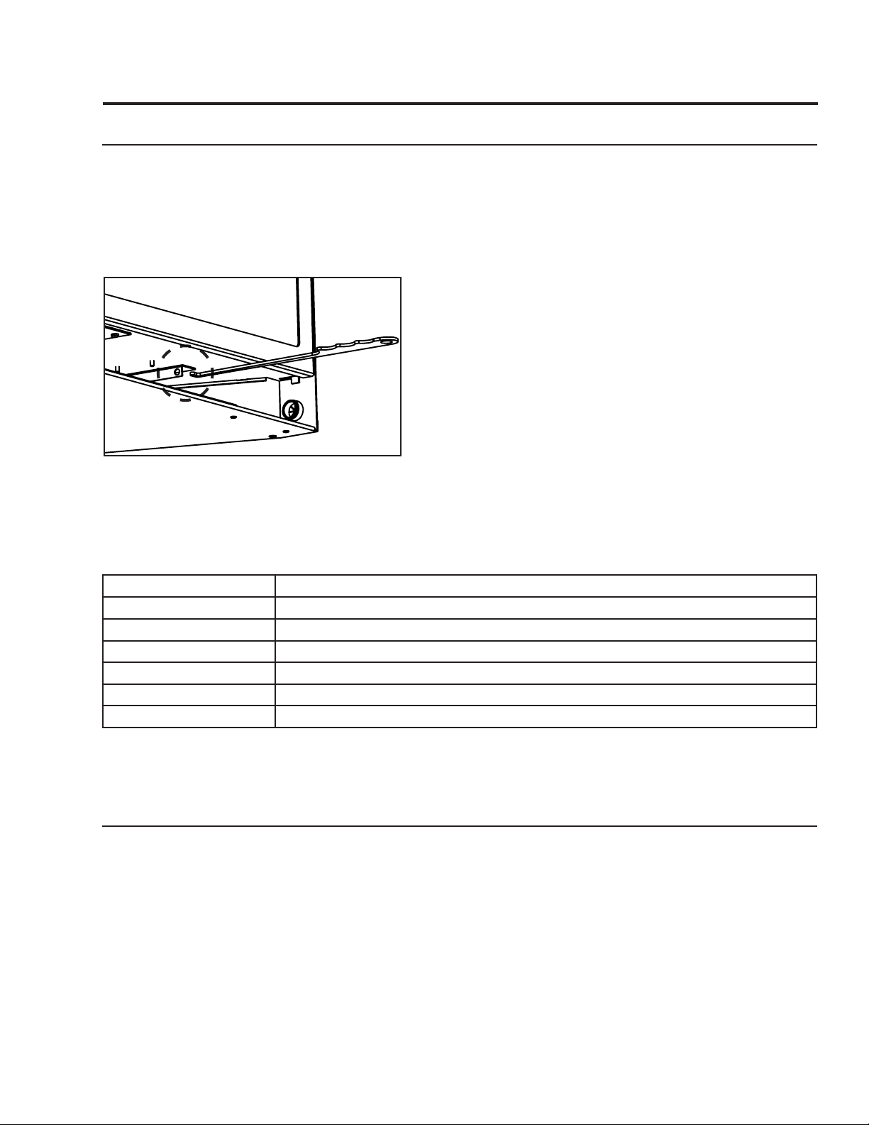
baffLe pLate aDjustment:
This appliance comes equipped with an adjustable bae plate that must remain closed when installation
Measure the height of the chimney beforehand and purchase the appropriate
venting. Never attempt to over-stretch a flexible liner to accommodate the
height of the chimney . Every joint in the venting must be secured with three (3)
#8 x 3/8” HWH sheet metal screws and an appropriate sealant (either silicone
or stove cement).
The flue damper must be fully blocked using a non-combustable seal off plate;
the smoke shelves, shields and baffles may be removed if attached by
mechanical fasteners.
The air intake liner must extend a minimum of 12” above the seal off plate.
The exhaust liner must connect to the termination.
The fireplace and fireplace chimney must be clean, in good working order and
constructed of non-combustible materials.
Make sure that all chimney cleanouts are tight fitting and will not permit air to
leak into the chimney . It must be completely sealed.
authories having jurisdicon in your area for restricons*
Figure 26: Alternate Installation of E30
ulitilizes the minimum permissable length of vent (8’ / 2.44m). For venting lengths between 20’-30’ (6.1
m-9.1 m) it may be necessary to adjust the bae plate, depending on installation and climate, to prevent
ames from lifting/ghosting during start-up.
To adjust the bae plate remove the door as shown in the
maIntenanCe anD serVICe - glass Door
remoVal. Then, using a Torx T20 screwdriver, slightly loosen (DO NOT remove) the two bae screws
indicated below in gure 27. Slide the the plate down to open the bae as needed (gure 28) then
re-tighten the screws to set the plate position. If ames continue to lift re-adjust the plate and conrm
venting, venturi setting, and log setup are all correct.
Figure 27: Bae plate screws
22
Figure 28: Bae plate adjustment
Page 23

Initial Installation
QUALIFIED INSTALLERS ONLY
instaLLing the unit:
• Remove the packaging from the appliance and check to make sure there is no damage. Carefully check
the glass door. Do not use the unit if it is damaged. In the event damage is found, please report it to
your dealer as soon as possible.
• Carefully clean the replace and ue before installing the stove. Failure to do so may result in fumes
or soot being blown into the room and may cause a re leading to death or serious injury.
instaLLation instRuctions:
1. Plan your installation and clearances to
combustibles. The E30 may be installed
and vented into any solid fuel replace
that has been installed in accordance
with the National, Provincial/State
and local building codes and has
been constructed of non-combustible
materials. Also refer to the Also refer
ClearanCes to CombustIbles section.
2. Remove door. See maIntenanCe anD
serVICe - glass Door remoVal.
3ft (0.9m)
Minimum
2ft (0.6m)
Minimum
Within
10ft (3m)
Figure 29: Roof Clearances.
Roof ridge or
any other portion
of a building
3. Remove wrapping material from log and embers and check for any damage. If damage is observed,
do not use unit and contact your local dealer.
4. Check that the chimney clean outs t properly. The ue damper must be fully blocked open or removed
for installation of the E30; the smoke shelves, shields and baes may be removed if attached by
mechanical fasteners.
Table 5: Vent termination clearances
Minimum Clearance* Description
3 ft (0.9 m)
24 in (0.6 m)
5 ft (1.5 m)
6 ft (1.83 m) Clearance to mechanical air supply inlet.
3ft (0.9m) Clearance to each side of center line extended above meter/regulator assembly.
6 ft (1.83 m) Radial clearance around service regulator vent outlet.
12 in (30 cm) Clearance above grade, verandah, porch, deck, or balcony.
3 ft (0.9 m)
9 in (0.23 m) Exception for inputs up to and including 50,000 Btu/h (15kW)
12 in (0.3 m)
Clearance above the highest point where it passes through a roof surface, refer to
Figure 29.
Clearance above a roof ridge, any other portion of a building, or any other obstruction within a horizontal distance of 10 feet (3 m), refer to Figure 29.
Clearance for a vent or chimney above either the highest connected appliance
drafthood outlet, or ue collar.
Clearance to a building opening or combustion air inlet of another appliance, except with the approval of the authority having jurisdiction for the following reduced
clearances.
Exception for inputs exceeding 50,000 Btu/h (15kW) but not exceeding 100,000
Btu/h (30kW)
*Clearances are in accordance with local installation codes and the requiremenets of the gas supplier
23
Page 24

Initial Installation
QUALIFIED INSTALLERS ONLY
5. Stretch the Ø3” (76mm) ex vent liners to the length needed to ensure they can be easily connected
to the vent terminals.
6. Install the ex pipe assembly up through the chimney,
ensure that the pipe slides through far enough to connect
ICC
EXCELDirect
onto the vent cap. Refer to table 6 to conrm the vent cap
is approved for use.
7. Most vent caps can be installed onto chimneys with ue
openings up to 16” (406mm) x 16” (406mm) when the
actual ashing is 16” x 16” or larger. If the chimney is
smaller, the ashing should be trimmed down and folded
Vertical
Termination
High-Wind
Shield
Flashing TF-MFR
TM-SVT*
TM-IVT
TM-SVTS 46DVA-VWG
over.
8. Apply a bead of stove cement sealant to the Ø3” (76mm)
Co-Linear
Adapter
TM-CTA
pipe of the exhaust vent terminal. Slide the ex liner onto
the vent terminal and secure with three (3) sheet metal
screws evenly spaced.
*Requires co-linear adapter
Table 6: Approved Terminations &
other parts
9. Place a bead of high temperature silicone on the intake
collar of the vent terminal. Slide the Ø3” (76mm) ex intake liner over the collar, secure the ex liner
with three (3) sheet metal screws evenly spaced. Secure the vent terminal to the chimney using
adequate sealant, and according to local building codes.
M&G
DirectVent
Pro
46DVA-VCH*
46DVA-GK
10. If the replace opening is lower than 24” (610 mm), remove the vent collar plate from the top of the
insert by unscrewing the two (2) T-20 Torx screws located on the center top of the stove above the
door opening (see Figure 30). Slide the collar plate backwards. Properly secure the vent collar plate
to the exible vent pipe liner(s) previously installed in the chimney. Be careful not to over-stretch the
liner(s).
11. Apply a bead of stove cement sealant to the top section of the Ø3” (76mm) exhaust vent collar plate.
Slide the Ø3” (76mm) ex vent over the ue collar and secure with three (3) sheet metal screws
evenly spaced.
12. Place a bead of high temperature silicone on the
intake collar of the replace, slide the Ø3” (76mm)
Vent Collar
Screws
ex intake liner over the collar, secure the ex liner
with three (3) sheet metal screws evenly spaced.
13. Place the unit part way into the replace. Connect
the gas line to the ⅜” NPT tting on the right side of
the unit using locally approved methods (see InItIal
InstallatIon - gas lIne ConneCtIon). R oute the power
cord so it can be connected to the power supply.
24
Figure 30: Vent Collar Plate Screw Location.
Page 25

Initial Installation
QUALIFIED INSTALLERS ONLY
14. As you push the unit into its nal position in the
replace, if the vent collar plate was removed,
reinstall it on the stove by pulling it into the
brackets on top and reinstall the two Torx T-20
screws.
15. Adjust the levelling legs to ensure the unit is
level and high enough if a base shelf and/or riser
is to be installed. There are four levelling legs on
the bottom of the unit (shown in Figure 31).
Figure 31: Levelling legs position.
zeRo cLeaRance (zc) fiRepLace instaLLation:
The metal oor of the ZC solid fuel rebox can be removed to allow the installation of the insert. THE
CLEARANCE TO COMBUSTIBLE MATERIAL UNDER THE INSERT IS 2 1/4” (57.2 mm). YOU MUST USE
THE LEVELING LEGS TO RAISE THE INSERT A MINIMUM OF 2 1/4” (57.2 mm) IF THE UNIT IS TO
BE INSTALLED ON COMBUSTIBLE MATERIAL. IF THE ZERO CLEARANCE FIREPLACE IS INSTALLED
DIRECTLY ONTO A CONCRETE FLOOR THE MINIMUM CLEARANCE IS NOT APPLICABLE. The optional
Base Shelf and Riser are recommended to ll the space under the unit once raised. The sidewalls and top
structure of the solid fuel rebox cannot be altered with the exception of: removal of dampers, removal
of smoke shelf or bae, removal of ember catches, removal of log grate, removal of viewing screen/
curtain, and removal of doors. THE ORIGINAL FIREPLACE MAY NEVER BE RETURNED TO SOLID FUEL
USE IN THIS CONDITION.
IMPORTANT: If the factory-built replace has no gas access hole(s) provided, an access hole of 1.5 inch
(37.5 mm) or less may be drilled through the lower sides or bottom of the rebox in a proper workmanship
like manner. This access hole must be plugged with non-combustible insulation after the gas supply line
has been installed. Cutting any sheet-metal parts of the replace, in which the gas replace insert is to
be installed, except as tested for the oor is prohibited.
The included label plate shown below must be permanently attached inside the cavity of the replace
in a visible location.
WARNING: This fireplace has been converted
for the use with a gas fireplace insert only and
cannot be used for burning wood or solid
fuels unless all original parts have been
replaced, and the fireplace re-approved by the
authority having jurisdiction.
Figure 32: Fireplace Altered Plate.
C-11168
25
Page 26

Initial Installation
QUALIFIED INSTALLERS ONLY
eLectRicaL RequiRements:
The replace must be electrically connected and grounded in accordance with local codes or, in the
absence of local codes, with the current CSA C22.1 Canadian Electrical Code Part 1, Safety Standar ds For
Electrical Installations, or The National Electrical Code ANSI / NFPA 70 in the US.
WARNING: The electrical grounding instructions must be followed. The unit is equipped with a threeprong (grounding) plug for your protection against shock hazard, and should be plugged directly into a
properly grounded three-prong outlet. DO NOT cut or remove the grounding prong from this plug.
CAUTION: When servicing controls, label all wires prior to disconnection. Wiring errors can cause
improper and dangerous operation. Verify proper operation after servicing. If any of the original wire as
supplied with the appliance must be replaced, it must be replaced with 18 AWG wire with a temperature
rating of at least 105°C.
Proflame 2 System w/ Battery Holder - Wiring Diagram
Transmitter - TMFSLA
(50-3265) / (0.584.040)
IFC Main Harness
(50-3030) /
(0.584.924)
Battery
Holder
(50-3204) /
(0.584.103)
Battery Holder
Harness
(50-3203) /
(0.584.922)
Main On/Off
(50-3205)
885 Gas Valve
(50-2682) /
(0.885.001)
To Main
Burner
PSE IPI Pilot
(50-3026)
Flame Sensor
Spark Electrode
26
Convection Fan
(50-2493)
IFC (50-3312) /
(0.584.325)
Power Cord
(EC-042)
Figure 33: Wiring Diagram.
Page 27

Initial Installation
QUALIFIED INSTALLERS ONLY
gas Line connection:
WARNING: Only persons licensed to work with gas piping
may make the necessary gas connections to this
appliance.
Gas Line Connection:
• A ⅜” NPT male pipe nipple (supplied with the unit) will
have to be turned into the valve at the lower left side rear
of this replace (see Figures 34 and 35). Consult the local
authorities for local codes or use the CAN/CGA B149 (1 or 2)
installation code in Canada. In the US, gas installations follow
either local codes or the current edition of the National Fuel
Gas Code ANSI Z223.1.
• If the factory-built replace has no gas access hole(s)
provided, an access hole of 1.5 in (37.5mm) or less may be
drilled through the lower sides or bottom of the rebox in a
proper workmanship like manner. This access hole must be
plugged with non-combustible insulation after the gas supply
line has been installed.
• A shut-o valve is not supplied with this unit but one should
be installed.
• The appliance and its shut-o valves must be disconnected
from the gas supply piping system during any pressure testing
where the pressure exceeds ½ psig (3.45 KPa) or the valve
will be damaged.
Table 7: Orice and Pressure Information.
E30 with Log Set
Main Burner Natural Gas Propane Gas
Figure 34: ⅜” NPT Male Pipe Nipple
with Cover Attached.
Figure 35: ⅜” NPT Male Pipe Nipple
with Cover Removed.
Orice: #37 DMS #52 DMS
Max. Manifold Press: 3.8 W.C. (0.95 KPa) 11.0 W.C. (2.74 KPa)
Min. Manifold Press: 1.2 W.C. (0.30 KPa) 2.7 W.C. (0.67 KPa)
Max. Supply Press: 10.5 W.C. (2.62 KPa) 13.0 W.C. (3.24 KPa
Min. Supply Press: 5.0 W.C. (1.24 KPa) 11.0 W.C. (2.74 KPa)
Max. Input: 33,000 BTU/hr (9.67 KW) 30,000 BTU/hr (8.79 KW)
Min. Input: 16,500 BTU/hr (4.84 KW) 15,000 BTU/hr (4.4 KW)
27
Page 28

Initial Installation
Pilot
Adjustment
Screw
Manifold Pressure
Tap
Inlet
Pressure
Tap
Servo
Regulator
Pilot
Solenoid
Burner
Solenoid
Gas IN
QUALIFIED INSTALLERS ONLY
TO TEST VALVE PRESSURES (INPUT RATES):
The pressure taps are located on the front side of the valve (see Figure 36).
1. Using a long at bladed screwdriver, turn set screw one (1) turn counter-clockwise to loosen.
2. Place 5/16 in (8 mm) I.D. hose over the pressure taps.
3. Check pressures using a manometer.
4. When nished, remove hose and tighten set screw.
Always check for gas leaks with a soap and water solution after completing the required
pressure test.
Figure 36: Valve Details.
NEVER USE AN OPEN FLAME FOR LEAK TESTING.
aDjusting the piLot fLame:
The pilot ow adjustment is set to maximum at the
factory and should not need to be adjusted. The pilot
ame should envelope ⅜” to ½” (10 to 13mm) of
the Flame sensor (see Figure 37). However, should
the need arise, follow Steps 1- 2 below.
1. The adjustment screw can be reached through
the front of the unit using a 10 inch long blade
head screw driver (see Figure 34 for location on
valve).
2. Turn the adjustment screw clockwise to decrease
or counterclockwise to increase pilot ame.
.375
-.500
(10-13mm)
Flame Sensor
Figure 37: Proper Pilot Flame.
28
Page 29

Secondary Installation
A
DETAIL A
SCALE 3 : 1
safety scReen instaLLation / RemoVaL:
To install the safety screen hold it upright in front of the replace with four (4) hooks pointing towards
the replace. Slide the hooks into the corresponding brackets on each side of the cabinet (see gures
38a and 38b). Ensure the hooks are secure to conrm correct installation. To remove the safety screen
unhook it from the brackets by liting up and out.
Figure 38a: Installing Safety Screen onto
Cabinet Bracket (Parts removed for clarity)
Figure 38b: Installing Safety Screen onto
Cabinet Brackets
optionaL base sheLf & RiseR:
The E30 Base Shelf (1⅝” (41 mm) high) and Base Shelf Riser (2⅛” (54 mm) high) are components that
can be combined to create a riser with an overall height of 23/16” (55 mm). This shelf can be installed
with or without the riser and can be used when the hearth in front of the unit is lower than the replace
opening. Additional Base Shelf Risers can be fastened together to increase the height in increments
of 2⅛” (54 mm). This Base Shelf may be used in conjunction with the any of the E30 surround panel
options, and it may also be used with the E30 Trimmable Surround. The Base Shelf and Riser are sold
separately.
Installation:
1. If unit is running, turn it o and
allow it to cool completely.
2. When using more than one riser
each level must be attached
using nine (9) #8 T-20 screws
provided (see Figure 39a).
3. If installing with riser(s) the
Base Shelf is to be fastened
Figure 39a: Combining 2 Base Shelf
Riser.
Figure 39b: Installing Base Shelf
onto Riser.
(see Figure 39b).
4. The leveling legs on the E30 may need to be adjusted to match
the height of the riser and shelf.
5. Center the Base Shelf assembly in front of the unit ush with the
bottom of the unit.
6. Install surround if required.
to the riser(s) with one T-20
screw at each end of the back
29
Page 30

Secondary Installation
optionaL 3 anD 4 siDeD tRimmabLe paneLs:
Modifying the Surround Panel:
The E30 Trimmable Surround Panels are large rectangular panels that may be cut for use in cases that a non-
standard replace opening (e.g. an arched opening) is to be lled. Optionally this surround can be left uncut
and placed in front of the replace opening.
1. Measure the replace opening and/or make a template of the replace opening.
2. Transfer the measurement to the Trimmable Surround.
3. If desired, oset the measurements by approximately
to be placed just inside the replace opening for a cleaner appearance.
4. Cut along the preferred line (from direct measurements of oset) and remove any sharp edges.
5. The panel can be touched up with a high temperature metallic black paint available from your dealer.
Panel Installation:
1. Install the two Trimmable Panel brackets onto the E30 unit using a T-20 Torx screwdriver. See Figures 40
and 41 for the screw installation locations. There are three sets of hole patterns on the brackets depending on
which Surround Panel is being installed. See Figures 42-44.
1
/8” (3mm) to the inside; this will allow for the panel
NOTE: The Extruded and Contemporary Surround Panels use the same holes for mounting the Side Cabinet
Extensions. The Regular Surround Panel uses its own set of holes.
Installed Brackets
Figure 40: Screw
Installation Locations.
Figure 41: Screw
Installation Locations.
Figure 42: Installation for Contemporary
and Extruded Surround.
30
Figure 44: Screw
Installation Locations.
Figure 43: Installation
for Regular Surround.
Page 31

Secondary Installation
suRRounD paneL instaLLation:
WARNING: The surround becomes hot when the unit is operating; ensure that the unit is turned o, and that
it has cooled to room temperature before beginning this installation.
Height Width
7
3-Sided Surround 25” (635 mm) 39
1
4-Sided Surround 31
Table 8: Surround Dimensions.
Please check components supplied with this kit. If components are missing or have been damaged, contact your
dealer, distributor or courier company before starting this installation.
IMPORTANT: The panel must not seal ventilation openings in the replace.
INSTALLATION (3 and 4 sided Surrounds):
Lift the face upright in front of the replace with the six hooks pointing towards the replace. Slide the hooks
over their corresponding screws (see Figures 45 & 46). Ensure the hooks are secure before releasing the
surround. The surround should be wiped with a damp cloth periodically. Screws can be tightened for a more
permanent install.
/2” (800 mm) 39 7/8” (1013 mm)
/8” (1013 mm)
REMOVAL:
Lift the surround straight up in order to unhook the notch on the hooks from the screws. Pull the surround aw ay
from the replace. Place the surround where it will not be damaged.
Access Panel
removed for
clarity.
Figure 45: Screw Locations. Figure 46: Screw and Hook Close-Up.
Burner Switch Blank INSTALLATION:
The burner switch supplied with the surround comes pre-installed and wired. This replace doesn’t require a
burner switch and it can be removed from the surround. Use the black switch blank supplied with the replace
manual to ll the hole in the surround panel where burner switch was for a cleaner appearance.
CLEANING: NEVER CLEAN FACES WHEN THEY ARE HOT. Turn o replace and allow to fully cool.
Painted surfaces should be periodically wiped with a damp cloth. Plated surfaces mut be free of ngerprints and
smudges prior to installation and should be cleaned with a clean soft rag and a small amount of Isopropyl
alcohol.
31
Page 32

Secondary Installation
fiRebox LineR anD buRneR tube RemoVaL:
NOTE: The rebox liners are fragile and should be handled gently.
1. Ensure the E30 is turned o and allow the unit to cool.
2. Remove the glass door as shown in the
WARNING: Do not touch or attempt to remove the glass if the replace is not completely cool.
Never operate the replace with the glass removed.
3. Remove the log set and all ember material (if installed).
4. Use the following steps to remove the liners and the burner tube.
NOTE: Follow the steps in the reverse order for reassembly.
maIntenanCe anD serVICe - glass Door remoVal.
Figure 47: The rebox with log set and media
removed.
Figure 49: The log grate is removed next by
simply lifting it o the grate tabs.
Figure 48: Carefully remove the front liner (if
installed) on the bottom of the rebox by picking
it up gently.
Figure 50: Remove the 6 screws highlighted in
gure 49 using a Torx T-20 screwdriver and
remove the air deector
Figure 51: Lift the burner o the mounts and pull
it out of the inlet box. The unscrew the panel
brackets (T20’s) from each side of the bae to
remove the left and right side liners.
32
Figure 52: The rear liner can now be r emoved. Use
a vacuum to clean up the bare rebox if needed.
Page 33

Secondary Installation
Log set anD embeR instaLLation (tRaDitionaL & biRch):
NOTE: The logs are fragile and should be handled gently. WARNING: Failure to position the parts in
accordance with these diagrams or failure to use only parts specically approved with this appliance may result in property
damage or personal injury. The underside of the logs are contoured and some contain pin holes to make alignment easier.
Using the pictures provided, carefully set the logs in place (see Figures 53 through 63).
Front Blocker
Figure 53: Unwrap the log grate and
painted front blocker from the foam
packaging. The front blocker MUST be
installed BEHIND the log grate. The
front blocker uses the same mounting
points as the log grate.
MUST be
installed
Figure 55: Place both the left and right
mid logs in the middle of the air deector.
Make sure the bottom holes align with
the pins in the air deector.
Figure 54: Install the back log on top of
the pilot on the back shelf of the air deector.
Push it against the back brick panel.
33
Page 34

Secondary Installation
Figure 56: Place the left top log on the
right, on top of the rear log and left mid
log. Locate the bottom on the far left
grate arm.
Figure 58: Pull apart Embaglow
and spread a thin even layer
over the burner area. Brush the
ember wool as ne as possible
(clump the wool together and
separate it using the supplied
brush) over the burner tube.
Place coals on the air deector
in front of both mid logs as
shown. Do Not cover the gaps
between the burner and air
deector.
Figure 57: Install the right top
log on top of rear log and right
mid log. Locate the bottom on the
far right grate arm.
34
Page 35

Secondary Installation
Figure 59: Place the center
top crossver log at an angle
on top of the rear log and left
mid log pins
Figure 60: Rest the
center top log on top of
the left mid log making
sure to align the bottom
with grate arm.
Figure 61: Place the center
front chunk log on the log
grate, close to the center, with
the front edge resting on the
right mid log.
Note: There are 2 locating
notches on the bottom side.
Bottom Notch = E30
Top Notch = E33
35
Page 36

Secondary Installation
Figure 62: Finally, rest the
left and right front chunks
on the log grate and burner as
shown.
DO NOT cover any burner
ports
TIP: While the glass is still
removed, it is recommended
that the gas line be purged
by lighting the pilot.
Figure 63: Proper installation and ame appearance
Log setup is now complete. Re-install the rebox door, then the safety screen.
Run the unit for 15 minutes then adjust the venturi as needed using the door tool. Figure 63 above
depicts what the burn and ame appearance shoud look like when the log set is properly installed and
venturi adjusted.
When re-lighting the replace for the rst time since the log set has been installed/replaced, watch
for ignition at ALL the burner ports. If a long delay is noticed, turn the appliance o and wait for it to
cool down. Then remove the glass and make sure none of the burner ports are blocked.
Maintenance: Once a year, the logs should be removed and checked for deterioration or large amounts
of soot. A small amount on the bottom side of the logs is normal. Remove and replace the logs in the
same manner described above.
If new logs are required, contact your nearest ENVIRO dealer.
36
Never operate the replace with the glass door removed.
Page 37

Troubleshooting
Diagnostic fLash coDes:
1. Fail to ignite: If there is no positive ignition, the board will go into lock out and the LED will blink 3 times
in intervals until the system is reset.
2. Low battery condition (<4V): the LED indicator will blink one (1) time in intervals.
3. Parasitic Pilot Flame: the LED indicator will blink two (2) times in intervals.
4. System Lock out: the LED indicator will blink three (3) times in intervals.
Additional Ignition Information
1. The Proame2 IFC will try two (2) times for ignition.
2. Each try for ignition will last approximately 60 seconds.
3. The wait time between the two tries is approximately 35 seconds.
LED Location
Figure 64: IFC LED Location
37
Page 38

Troubleshooting
Problem Possible Cause Solution
Thermostat
does not work
No spark
generation
No pilot ame
ignition
The pilot ame has gone out
The On/O switch is turn to OFF
The thermostat is set too high
Spark developes near the pilot
assembly or could occur onboard
No spark from the igniter
Air in the gas line
Pilot gas pressure dropout upon
main burner gas valve opening
No gas ow out of the pilot burner
7-Days of burner inactivity.
· Turn it ON
· Set the thermostat to a lower temperature
· Check pilot assembly wiring
· Check for broken or poor connection from the sparker to the
electrode
· Check for the spark shorting or arcing at other locations
· Check for defective sparker and spark electrode
· See “no spark generation”
· It takes a while for all the air to purge out of the pilot before gas
can reach the pilot and ignite
· Check gas mains supply and pressure
· Check gas valve wirings and connections to the board
· Check the pilot burner for obstruction
· Check the wirings and connections between the pilot assembly and
the board
· Check the correct gas type settings on the valve and pilot burner
assembly orice
• The pilot will automatically turn o when the burner has not
been used for 7 consecutive days. Re-light pilot to reset the
counter.
Pilot will not
remain lit
Remote
control does
not work
No reaction to
command
Problem with Flame Sensor circuit
The pilot light has gone out
The remote is too far away from
the heater
The battery holder is turned “OFF”
One of the two remote control or
battery holder batteries are dead
Battery holder or transmitter
batteries are low
A maximum number of failed
ignitions or ame restorations have
been reached.
No communication between the
remote control and the IFC
· Check for proper connection of the Flame Sensor to the IFC board
· Check pilot for full ame impingement around Flame Sensor
· If ame is too small, check gas pressure, adjust pilot rate screw,
check pilot head for damage
· Ensure the ground wire is properly attached to the pilot mounting
bracket and that it is makes a good electrical connection.
· See “Pilot will not remain lit”
· Use the remote closer to the heater
· Check the remote control instructions
· Replace the batteries
· Replace the batteries
· Remove any possible blocking conditions. See “locking conditions”
· See how to reset the board from Lockout
· Reprogram the transmitter to the battery holder.
· Follow the initializing system for the rst time
38
Page 39

Troubleshooting
Problem Possible Cause Solution
· Turn the system o by pressing the ON/OFF button on
the transmitter
· After approximately 2 seconds press the ON/OFF button
on the transmitter again.
· In the manual ame control mode, use the down arrow
button to reduce the ame to o, indicated by the word
Locking
conditions
Main burners
will not start
Flame lifting
Blue Flames
Reset the Proame IFC board
The pilot ame has gone out · See “Pilot will not remain lit”
The remote control is not working
correctly
The thermostat is disconnected or
set too high
Leak in vent pipe · Check for leaks in vent connections
Improper vent conguration
Terminal may be re-circulating ue
gases
The heater has just been started
Improper air shutter adjustment
OFF displayed on the transmitter LCD screen.
· Wait approximately 2 seconds and press the up arrow
button, the ignition sequence will start.
· With the transmitter o, move the slider switch on the
battery holder to the OFF position.
· Wait approximately 2 seconds and move the battery
holder slider switch to the ON position.
· Replace the batteries
· Set the thermostat to a lower temperature
· Check vent conguration with manual
· Check positioning of bae plate
· Check to see if terminal is on correctly
· May need to install high wind termination cap.
· Contact dealer
· Normal during start up: ame will yellow as the replace
heats up
· Decrease primary air by closing the air shutter
Glass fogs up
Flames are
burning
“dirty” or
sooting
Normal condition: after the
appliance warms up the glass will
be clear.
The logs or glasses are placed
incorrectly
Improper air shutter adjustment
Incorrect rating input
**Due to additives in gas, glass may get hazy during
operation** Clean as needed.
· Check log positioning
· Check level of glasses layout
· Increase primary air by opening the air shutter
· Check for proper venting and blockage of the vent
termination
· See also “Burners will not remain lit”
· Check manifold pressure and clock input rating for over-
ring
· Conrm orice size is correct
39
Page 40

Parts List
Reference
Number
1 E30 DV Flue Adaptor Bottom Gasket 50-2497
- E30I Owner’s Manual 50-2597
- E30I Conversion Kit NG to LP 50-2486
- E30I Conversion Kit LP to NG 50-2541
2 E30 Door Release Tool 50-2510
- Ceramic Wool Embers Only 50-893
3 Domestic Power Cord (115V) EC-042
4 Heyco Strain Relief EC-044
5 E30 Pilot Shield 50-2500
6 Pilot Gasket EC-021
7 PSE IPI Pilot Assembly 50-3026
8 E30/E33 H-Burner Tube 50-3653
9 E30 Valve Cover with Gasket 50-2503
10 885 Proame IPI Valve NG 50-2682
11 Proame 2 Battery Holder (0.584.103) 50-3204
- Battery Holder Wire Harness (0.584.922) 50-3203
12 Proame 2 IFC (0.584.325) 50-3312
- IFC Wire Harness (0.584.924) 50-3030
- IFC ON/OFF Jumper Only 50-3205
13 Proame 2 Transmitter (TMFSLA) 50-3265
14 E30 Door Complete 50-2505
15 E30 Glass C/W Gasket (21.75” X 13.575”) 50-2506
16 Dual Bulb Door Gasket (10ft) 50-634
17 E30 Replacement Safety Screen 50-3072
18 Convection Fan Only 50-2493
19 E30 Door Latch Mechanism (Set of 2) 50-2507
20 Brick Liner Set - E30 50-2509
Part Description Part Number
40
- Porcelain Liner Set - E30 50-2427
- E30/E33 Traditional Logset (10 pcs) 50-3627
- E30/E33 Birch Logset (10 pcs) 50-3628
- 12 oz. Can of Metallic Black Touch Up Paint PAINT-12-MB
- Blank Filler Switch EG30-010
Page 41

Parts Diagram - Components
14
15
16
9
20
19
8
7
18
1
6
5
12
10
17
11
13
2
4
3
41
Page 42

Notes
42
Page 43

Warranty for Enviro Gas Products
Sher wood Industries Ltd. (“Sherwood”) hereby warrants, subject to the terms and
conditions herein set forth, this product against defects in material and workmanship
during the specified warranty period starting from the date of original purchase at retail.
In the event of a defect of material or workmanship during the specified warranty period,
Sherwood reserves the right to make repairs or to assess the replacement of a defective
product at Sherwood’s factory. The shipping costs are to be paid by the consumer.
All warranties by Sherwood are set forth herein and no claim shall be made against
Sherwood on any oral warranty or representation.
Conditions
A completed warranty registration must be submitted to Sherwood within 90 days
of original purchase via the online warranty registration page or via the mail-in
warranty registration card provided. Have the installer fill in the installation data
sheet in the back of the manual for warranty and future reference.
This warranty applies only to the original owner in the original location from date of
install.
The unit must have been properly installed by a qualified technician or installer, and
must meet all local and national building code requirements.
The warranty does not cover removal and re-installation costs.
Sherwood Industries Ltd. reserves the right to make changes without notice.
Sherwood Industries Ltd. and its employees or representatives will not assume
any damages, either directly or indirectly caused by improper usage, operation,
installation, servicing or maintenance of this appliance.
A proof of original purchase must be provided by you or the dealer including serial
number.
This warranty does not cover any discoloration of the safety screen mesh.
Exclusions
An expanded list of exclusions is available at www.enviro.com/help/warranty.html
This warranty does not cover:
mage as a result of improper usage or abuse.
Da
Damage caused from over-firing due to incorrect setup or tampering.
Damage caused by incorrect installation.
To the Dealer
Provide name, address and telephone number of purchaser and date of purchase.
Provide date of purchase. Name of installer and dealer. Serial number of the
appliance. Nature of complaint, defects or malfunction, description and part # of any
parts replaced.
Pictures or return of damaged or defective product may be r
To the Distributor
Sign and verify that work and information are correct.
Sherwood Industries Ltd.
6782 Oldfield Road, Victoria, BC . Canada V8M 2A3
Online warranty registration: www.enviro.com/warranty/
equired.
Category One Year Two Year Limited Lifetime (7yr)
1,2
Parts
Firebox Liner Panels
Firebox
Heat Exchanger
Burner
Ceramic Logs
Ceramic Glass
Pedestal / Legs
Door Assembly
Surround Panels
Exterior Panels
Electrical Components
Exterior Surface Finishing
Labour
(unit serial numb er required)
3
4
5
(excluding nis h)
(excluding nish)
(excluding nis h)
Up to 5 years
1
Whereas warranty has expired, replacement parts will be warrantied for 90 days from part purchase date. Labour not included.
Unit serial number required.
2
50-173 Westport Fan Kit covered for up to 5 years from purchase date. Labour not included. Unit serial required.
3
Excluding damage to the nish caused by improper setup of the appliance, or color changes.
4
Log set and panels excludes wear and tear or breakage caused by cleaning or service.
4
Glass is covered for thermal breakage. Photos of box, inside of door, and unit serial # must be supplied for breakage due to shipping.
6
Exterior Surface nishing covers plating, enamel or paint and excludes colour changes, chipping, and ngerprints.
Travel costs not included.
Jan 2018
43
Page 44

Installation Data Sheet
The following information must be recorded by the installer for warranty purposes and future reference.
NAME OF OWNER:
_________________________________________
ADDRESS:
_________________________________________
_________________________________________
_________________________________________
PHONE:___________________________________
MODEL:___________________________________
SERIAL NUMBER:___________________________
DATE OF PURCHASE: _____________ (dd/mm/yyyy)
NAME OF DEALER:
_________________________________________
ADDRESS:
_________________________________________
_________________________________________
_________________________________________
PHONE:___________________________________
NAME OF INSTALLER:
_________________________________________
DATE OF INSTALLATION:___________(dd/mm/yyyy)
� DIRECT VENT
� NATURAL GAS (NAT) � PROPANE(LPG)
INLET GAS PRESSURE:_________in WC
MAIN BURNER ORIFICE:__________# DMS
PILOT ORIFICE #_________OR________in diam.
INSTALLER’S SIGNATURE:
_________________________________________
MANUFACTURED BY:
SHERWOOD INDUSTRIES LTD.
6782 OLDFIELD RD. SAANICHTON, BC, CANADA V8M 2A3
www.enviro.com
March, 2020
ADDRESS:
_________________________________________
_________________________________________
_________________________________________
PHONE:___________________________________
C-15550
 Loading...