

Page 1

WARRANTY REGISTRATION
enviro.com/warranty
E30GI
GAS INSERT - Glass Burner & Proame IPI Valve
OWNER’S MANUAL
WARRANTY REGISTRATION
enviro.com/warranty
WARNING: If the information in this manual is not followed exactly,
a re or explosion may result causing property damage, personal
injury or loss of life. Installation and service must be performed by a
Report # 268-S-23-5
Version Française: www.enviro.com/fr.html
qualied installer, service agency or the gas supplier.
50-2581
Page 2

Safety Precautions
WARNING:
FIRE OR EXPLOSION HAZARD
Failure to follow safety warnings exactly could result in serious
injury, death, or property damage.
- Do not store or use gasoline or other ammable vapors and
liquids in the vicinity of this or any other appliance.
- WHAT TO DO IF YOU SMELL GAS
• Do not try to light any appliance.
• Do not touch any electrical switch; do not use any phone in your
building.
• Leave the building immeadiately.
• Immeadiately call your gas supplier from a neighbor’s phone.
Follow the gas supplier’s instructions.
• If you cannot reach your gas supplier, call the re
department.
- Installation and service must be performed by a qualied
installer, service agency or the gas supplier.
INSTALLER:
Leave this manual with the appliance.
CONSUMER:
Retain this manual for future reference.
This appliance may be installed in an after-market permanently located,
manufactured (mobile) home, where not prohibited by local codes.
This appliance is only for use with the type of gas indicated on the rating plate. This
appliance is not convertible for use with other gases, unless a certied kit is used.
Massachusetts installations (Warning): This product must be installed by a licensed plumber or
gas tter when installed within the Commonwealth of Massachusetts. Other Massachusetts code
requirements: Flexible connector must not be longer than 36in., a shut off valve must be installed;
only direct vent sealed combustion products are approved for bedrooms/bathrooms. A carbon
monoxide detector is required in all rooms containing gas red direct vent appliances. The replace
damper must be removed or welded in the open position prior to installation of a replace insert.
2
Page 3

Safety Precautions
HOT GLASS WILL
CAUSE BURNS
DO NOT TOUCH GLASS
UNTIL COOLED.
NEVER ALLOW CHILDREN
TO TOUCH GLASS.
A barrier designed to reduce the risk of burns from the
hot viewing glass is provided with this appliance and shall
individuals.
FOR SAFE INSTALLATION AND OPERATION OF YOUR “ENVIRO” HEATER,
PLEASE CAREFULLY READ THE FOLLOWING INFORMATION:
• All ENVIRO gas-red appliances must be installed
in accordance with their instructions. Carefully read all
the instructions in this manual rst. Consult the building
authority having jurisdiction to determine the need for a
permit prior to commencing the installation.
• NOTE: Failure to follow these instructions could
cause a malfunction of the replace, which could result in
death, serious bodily injury, and/or property damage.
• Failure to follow these instructions may also void
your re insurance and/or warranty.
GENERAL
• Installation and repair should be done by a qualied
service person. The appliance should be inspected before
the rst use and, at least, annually by a qualied service
person. More frequent cleaning may be required due to
excessive lint from carpeting, bedding material, etc. It
is imperative the control compartments, burners and
circulating air passageways of the appliance be kept
clean.
• Due to high temperatures, the appliance should be
located out of high trafc areas and away from furniture
and draperies.
Children and adults should be alerted to the
hazards of high surface temperatures and should
stay away to avoid burn or clothing ignition.
• Young children should be carefully supervised when
in the same room as the appliance. Toddlers, young
children and others may be susceptible to accidental
contact burns. A physical barrier is recommended if there
are at risk individuals in the house. To restrict access to a
replace or stove install an adjustable safety gate to keep
toddlers, young children and other at risk individuals out
of the room and away from hot surfaces.
• Clothing or other ammable materials should not be
placed on or near the appliance.
• Always keep the area around these appliances clear of
combustible material, gasoline and other ammable liquids
and vapours.
• These appliances should not be used as a drying rack
for clothing or for hanging Christmas stockings/decorations.
• Due to the paint curing on the stove, a faint odor and
slight smoking will likely be noticed when the stove is rst
used. Open a window until the smoking stops.
Always connect this gas stove to a vent system and vent to
the outside of the building envelope. Never vent to another
room or inside the building. Make sure the specied vent
pipe is used, properly sized and of adequate height to
provide sufcient draft. Inspect the venting system annually
for blockage and signs of deterioration.
WARNING: Failure to position the parts in accordance
with the diagrams in this booklet, or failure to use only
parts specically approved with this appliance, may result in
property damage or personal injury.
WARNING: Do not operate with the glass front removed,
cracked or broken. Replacement of the glass should be done
by a licensed or qualied service person.
• Never use solid fuels such as wood, paper, cardboard,
coal, or any ammable liquids, etc., in this appliance.
• Do not use this heater if any part has been under water.
Immediately call a qualied service technician to inspect the
heater and to replace any part of the control or gas control
systems that have been under water.
• Do not abuse the glass by striking it or slamming the
door shut.
• If the E30GI unit is pulled out of its installation, and
the vent-air intake system is disconnected for any reason,
ensure that the vent-air intake pipes are reconnected and
re-sealed in accordance to the instructions noted in InItIal
InstallatIon - VentIng FIreplace Inserts.
FOR YOUR SAFETY
• Installation and service must be performed by a qualied
installer, service agency or gas supplier.
• This installation must conform to local codes or, in
the absence of local codes, to the current CAN/CGA-B149
installation code (Canada) or National Fuel Gas Code ANSI
Z223.1.2 (USA)
• To prevent injury, do not allow anyone who is unfamiliar
with the stove to operate it.
To prevent injury, if the pilot or pilot and burners
•
have gone out on their own, open the glass door and
wait 5 minutes to air out before attempting to re-
light the stove.
3
Page 4

Table of Contents
Safety Precautions...........................................................................................................2
Table of Contents.............................................................................................................4
Codes And Approvals.......................................................................................................5
Specications..................................................................................................................6
Rating Label Location...........................................................................................6
Dimensions..........................................................................................................6
E30I Options Dimensions.....................................................................................7
Operating Instructions.....................................................................................................8
Lighting and Turning Off Instructions.....................................................................8
Venturi Adjustment...............................................................................................9
Normal Sounds During Operation.........................................................................9
Remote Control Operations...................................................................................9
Switching to Continuous Pilot Mode........................................................................10
Wall Mounting the Receiver.................................................................................12
Initializing the System for the First Time..............................................................12
Maintenance And Service................................................................................................15
Cleaning The Glass.............................................................................................15
Cleaning The Firebox..........................................................................................15
Replacing The Glass............................................................................................15
Check Pilot and Burner Flames............................................................................15
Glass Door Removal...........................................................................................16
Cleaning The Painted Surfaces............................................................................16
Removing Valve Cover.........................................................................................17
Fuel Conversion..................................................................................................18
Initial Installation...........................................................................................................20
Clearances to Combustibles.................................................................................20
Minimum Fireplace Size.......................................................................................20
Direct Vent Model...............................................................................................20
Venting Fireplace Inserts.....................................................................................21
Direct Vent Vertical Vent Termination...................................................................23
Installing the Unit...............................................................................................24
Zero Clearance Fireplace Installation...................................................................25
Electrical Requirements.......................................................................................26
Gas Line Connection...........................................................................................27
Adjusting The Pilot Flame....................................................................................29
Secondary Installation....................................................................................................30
Optional Base Shelf & Riser.................................................................................30
Extension Bracket Removal..................................................................................31
Reduced Depth Optional 3 and 4 sided Trimmable Panels...........................................33
Regular Depth Optional 3 and 4 sided Trimmable Panels...........................................34
Surround Panel Installation..................................................................................35
Safety Screen Installation.....................................................................................36
Firebox Liner and Burner Tray Removal / Installation..............................................37
Installing the Glass Beads...................................................................................38
Trouble Shooting............................................................................................................39
Parts List.......................................................................................................................42
Parts Diagram - Components..........................................................................................44
Parts Diagram - Options.................................................................................................45
Warranty.......................................................................................................................47
Installation Data Sheet...................................................................................................48
4
Page 5

Codes And Approvals
DIRECT VENT: This type is identied by the sufx DV. This appliance draws all of its air for combustion from
outside the dwelling, through a specially designed vent pipe system.
This appliance has been tested and approved for installations from 0 feet to 4500 feet (1372 m) above sea level.
In the USA: The appliance may be installed at higher altitudes. Please refer to your American Gas Association
guidelines which state: the sea level rated input of Gas Designed Appliances installed at elevations above 2000
(610 m) feet is to be reduced 4% for each 1000 feet (305 m) above sea level. Refer also to local authorities
or codes which have jurisdiction in your area regarding the de-rate guidelines.
In Canada: When the appliance is installed at elevations above 4500 feet (1372 m), the certied high altitude
rating shall be reduced at the rate of 4% for each additional 1000 feet (305 m).
• This appliance has been tested by OMNI-Test Laboratories and found to comply with the established
VENTED GAS FIREPLACE HEATER standards in CANADA and the USA as follows:
DIRECT VENTED GAS FIREPLACE INSERT HEATER
TESTED TO: ANSI Z21.88-2014/CSA 2.33-2014 VENTED GAS FIREPLACE HEATERS
CAN/CGA 2.17-M91 (R2009) GAS FIRED APPLIANCES FOR HIGH ALTITUDES
CSA P.4.1-09 TESTING METHOD FOR MEASURING ANNUAL FIREPLACE EFFICIENCY
This ENVIRO E30GI Fireplace Insert:
• Has been certied for use with either natural or propane gases. (See rating label.)
• Is not for use with solid fuels.
• Is approved for bedroom or bed sitting room. (IN CANADA: must be installed with a permanent wall thermostat
for bedroom installations. Consult the authority having local jurisdiction in your area. IN USA: see current ANSI
Z223.1 for installation instructions.)
• Must be installed in accordance with local codes. If none exist, use current installation code CAN/CGA B149 in
Canada or ANSI Z223.1/NFPA 54 in the USA.
• Must be properly connected to an approved venting system and not connected to a chimney ue serving a
separate solid-fuel burning appliance.
• Is not approved for closet or recessed installations.
IMPORTANT NOTICE (Regarding rst re up): When the unit is turned on for
the rst time, it should be turned onto high without the fan on for the rst 4
hours. This will cure the paint, logs, gasket material and other products used in
the manufacturing process. It is advisable to open a window or door, as the unit
will start to smoke and can irritate some people. After the unit has gone through
the rst burn, turn the unit off, let the unit get cold then remove the glass door
and clean it with a good gas replace glass cleaner, available at your local ENVIRO
dealer. See “Door remoVal” and “cleanIng the glass” sections.
5
Page 6

Specifications
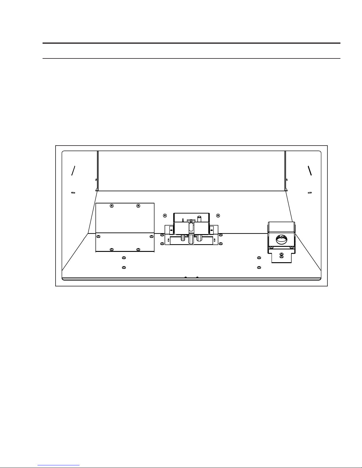
Rating LabeL Location:
The rating label is located on the bottom of the unit, behind the front access door.
Dimensions:
17.89
6.94
6.94
21.07
18.62
2.07
16.49
1.30 3.07
15.67
17.71
19.60
15.61
27.50
26.59
24.38
14.06
FRONT
LEFT RIGHT
13.76
16.27
2.36
instaLL Depth:
If the available depth of install is less than the 17.71” shown above, the stove depth can be
reduced to 15.67” by removing the cabinet extension brackets; however, doing so will cause
the safety screen to protroud past the front of the surround panel. If the reduced install depth
is required, the extension brackets must be removed. Refer to Secondary Installation pages
27-29 for instructions.
Figure 1: E30 Exterior Dimensions.
6
Page 7

27
Specifications
5
39
"
8
25"
3
"
8
5
41
"
8
Figure 2: E30GI Contemporary Surround with Base Shelf and Riser.
Table 1: E30GI Options Dimensions.
Regular Surround Contemporary Surround Extruded Surround
Height 25” (635mm) 25” (635mm) 25” (635mm)
7
Width 39
Trimmable
Surround
/8” (1013 mm) 39 7/8” (1013 mm) 39 7/8” (1013 mm)
Height Width
38” (965mm) 46” (1168mm)
Base Shelf Base Shelf Riser
Height 1 ⅝” (41mm) 2 ⅛” (54mm)
Width 41
Depth Bottom 4 ⅞” (112mm); Top 3
5
/8” (1057mm) 40 1/4” (1022mm)
13
/16” (97mm) 3
11
/16” (94mm)
7
Page 8

Operating Instructions
For Your Safety, Read Safety Precautions And Lighting Instructions Before Operating
WARNING: IF YOU DO NOT FOLLOW THESE INSTRUCTIONS EXACTLY A FIRE OR EXPLOSION
MAY RESULT, CAUSING PROPERTY DAMAGE, PERSONAL INJURY OR LOSS OF LIFE.
Lighting anD tuRning off instRuctions:
FOR YOUR SAFETY READ BEFORE OPERATING
WARNING:IF YOU DO NOT FOLLOW THESE INSTRUCTIONS EXACTLY, A FIRE OR EXPLOSION
MAY RESULT CAUSING PROPERTY DAMAGE, PERSONAL INJURY OR LOSS OF LIFE.
A. This appliance is equipped with an ignition device
which automatically lights the pilot. Do not try to
light the pilot by hand.
B. BEFORE OPERATING smell all around the
appliance area for gas. Be sure to smell next to the
floor because some gas is heavier than air and will
settle on the floor.
WHAT TO DO IF YOU SMELL GAS:
Do not try to light any appliance.
Do not touch any electrical switch; do not use any
phone in your building.
Immediately call your gas supplier from a
neighbor’s phone. Follow the gas supplier’s
instructions.
If you cannot reach your gas supplier, call the
fire department.
OPERATING INSTRUCTIONS
C. Use only your hand to push in or
turn the gas control knob. Never
use tools. If the knob will not push
in or turn by hand, don’t try to
repair it, call a qualified service
technician. Force or attempted
repair may result in a fire or
explosion.
D. Do not use this appliance if any
part has been under water.
Immediately call a qualified service
technician to inspect the appliance
and to replace any part of the
control system and any gas control
which has been under water.
1. STOP! Read the safety information above on this label.
2. Read the owner's manual including the section on
"Remote Control" operation.
3. Set the thermostat to the lowest setting.
4. Turn off all electric power to the appliance.
5. Do not attempt to light the pilot by hand.
6. Wait five (5) minutes to clear out any gas. Then smell for
gas, including near the floor. If you smell gas, STOP!
Follow "B" in the safety information above on this label.
If you don't smell gas, go to the next step.
7. Turn on all electric power to the appliance.
8. Using the remote control, set
thermostat to desired setting, or
press the ON/OFF key on the
remote. "ON" will be indicated on the
display of the remote and an audible
"beep" will be heard at the unit to
indicate the command has been
received.
9. This appliance is equipped with a
completely automatic ignition and
lighting control. The control will
attempt to light the pilot several
times if necessary. If it is
unsuccessful, it will discontinue
operations. If the appliance will
not operate, follow the
instructions "To Turn Off Gas To
Appliance" and call your service
technician or gas supplier.
Blue LCD Display
ON/OFF Key
THERMOSTAT Key
UP/DOWN Arrow Key
MODE Key
TO TURN OFF GAS TO APPLIANCE
1. Set thermostat to lowest setting, or press the ON/OFF Key. "OFF" will be indicated on the display
and an audible "Beep" will be heard at the unit to indicate the command has been received.
2. Turn off all electric power to the appliance if service is to be performed.
C-12455
Figure 3: Lighting instruction label.
8
Page 9

Operating Instructions
VentuRi aDjustment:
The venturi adjustment lever is located on the right side of the unit, below the door (see Figure 4). To
avoid touching hot surfaces under the unit, use the Door Tool to adjust the venturi.
The venturi allows the amount of air coming into the replace to be adjusted in order to accommodate
different climates and venting arrangements. Start the pilot and then the burner. Make sure the pilot
ame is burning normally and none of the burner ports are plugged. Let the replace burn for roughly
fteen (15) minutes and then examine the ames. The
ideal ame will be blue at the base and light orange
above. The ames should be of medium height. If the
ames look like this, no venturi adjustment is needed. If
the ames are fairly short and mostly blue, the replace
is getting too much air. Therefore, the air shutter should
be closed (push in) slightly until the correct ames are
achieved. Flames that are very orange, with tall dark
stringy tips are not getting enough air. Open (pull out)
the venturi until the ames clean up. If the venturi is
opened, then closed all the way, and the correct ames
Figure 4: Adjusting the venturi air setting.
Warning: Incorrect venturi adjustment may lead to improper combustion, which is a safety hazard.
Contact the dealer if there is any concern about the venturi adjustment.
cannot be attained, turn off the gas and contact the
dealer.
noRmaL sounDs DuRing opeRation:
Component Sound & Reason
Fire Box Creaking when heating up or cooling down.
Burner Light pop or poof when turned off; this is more common with LP units.
Temperature Sensor Clinking when it senses to turn the blower on or off.
Pilot Flame Quiet whisper while the pilot ame in on.
Blower / Fan Air movement that increases and decreases with the speed of the blower.
Gas Control Valve Dull click when turning on or off, this is the valve opening and closing.
Receiver Beeps when remote control buttons are pressed.
Table 2: Normal Sound
Remote contRoL opeRations:
The Proame GTM is a modular remote control system that directs the functions of the E30GI. The
Proame GTM is congured to control the on/off main burner operation, its ame levels and provides on/
off and Smart thermostatic control of the appliance.
9
Page 10

Operating InstructionsOperating Instructions
ATTENTION!
- TURN “OFF” THE MAIN GAS SUPPLY OF THE APPLIANCE DURING INSTALLATION OR
MAINTENANCE OF THE RECEIVER.
- PLACE THE RECEIVER’S 3 POSITION SLIDER SWITCH IN THE “OFF” POSITION DURING
INSTALLATION OR MAINTENANCE.
- TURN “OFF” MAIN GAS SUPPLY TO THE APPLIANCE PRIOR TO REMOVING OR REINSERTING
THE BATTERIES IN THE RECEIVER.
- DURING APPLIANCE INSTALLATION/MAINTENANCE OR IN CASE OF REMOTE CONTROL
MALFUNCTION TURN OFF THE FAN CONTROL MODULE USING THE “ON/OFF” MAIN POWER
SWITCH ON THE FRONT PANEL OF THE FCM.
technicaL Data
Transmitter (Remote Control):
Supply voltage 4.5 V (three 1.5 V AAA batteries)
Ambient temperature ratings 0 - 50 °C (32 - 122 °F)
Receiver:
Supply voltage 6.0 V (four 1.5 V AA batteries)
system DescRiption:
The Proame Remote Control System consists of two elements:
1. Proame Transmitter.
2. Proame Receiver and a wiring harness to connect the Receiver to the gas valve and stepper motor.
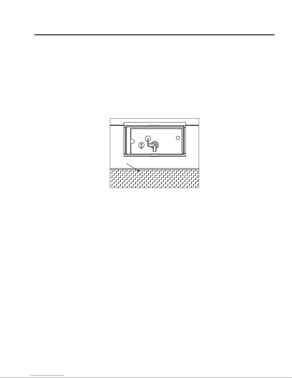
switching to continuous piLot moDe:
The toggle switch located on the bottom right corner switches the unit between intermittent and
continuous pilot modes. NOTE: It is recommended to use the continuous pilot mode during the
winter when the outside temperature is below 50°F (10°C) to keep the chimney properly
heated for updraft during burner ignition. Continuous pilot mode also keeps the rebox warm
which eliminates both heat loss to cold air that is trapped inside the rebox as well as excessive exhaust
vapour condensation on the door glass.
10
Page 11

Operating Instructions
TRANSMITTER (Remote Control with LCD
Display)
The Proame Transmitter uses a streamline
design with a simple button layout and
informative LCD display (Figure 5). The
Transmitter is powered by three (3) AAA type
batteries. A Mode Key is provided to Index
between the features and a Thermostat
Key is used to turn on/off or index through
Thermostat functions (Figure 5 & 6).
Figure 5: Proame Transmitter.
CPI Mode
Figure 6: Proame Transmitter LCD Screen.
RECEIVER
The Proame Receiver (Figure 7) connects directly to
the gas valve, stepper motor, DFC, and Fan Control
Module with a wiring harness. The Receiver is
powered by four (4) AA type batteries. The Receiver
accepts commands via radio frequency from the
Transmitter to operate the appliance in accordance
with the particular Proame system conguration.
The Receiver three (3) position slider switch can be
set to one of three positions: ON (Manual Override),
Remote (Remote control), or Off.
Figure 7: Proame Receiver.
Blower Speed
The blower will come on only when the replace
is up to temperature (approximately 15 minutes).
Rotating the fan controller knob will change the
speed of the fan (refer to Figure 8). To turn the
blower off, fully rotate the fan controller knob
counter-clockwise.
Figure 8: Fan Control.
11
Page 12

Operating Instructions
Wall Plate
Slider
Switch
Receiver
J-Box
Remote mounting the ReceiVeR (optionaL):
The receiver can be removed from the unit and placed inside a standard Junction type wall box or another
convenient location. This installation can take place up to 6’ft (1.8 m) from the appliance control valve.
1. Connect the wiring harness to the back of the
Receiver.
2. Install the Receiver in the Junction box using the
existing J box screws (Figure 9).
3. Insert the four (4) AA type batteries in the battery
compartment with the correct polarity.
4. Place the slider into the cover plate.
5. Put the Receiver switch in the “OFF” position.
6. Make sure the Receiver and cover plate words “ON”
and “UP” are on the same side.
7. Align the slider with the switch on the Receiver and
couple the switch into the slider.
8. Align the screw holes.
9. Using the two (2) screws provided secure the cover
Figure 9: Wall Mounting the Receiver.
plate to the Receiver.
opeRating pRoceDuRe:
Initializing The System For The First Time
Install the four (4) AA batteries into the receiver battery bay. Note the polarity of the battery and insert into
the battery bay as indicated on the Battery cover (+/-). Place the 3-position slider switch in the “Remote”
position (see Figure 7). Using the end of a paper clip, or other similar object, insert the end of the paper clip
into the hole marked “PRG” on the Receiver front cover (see Figure 7).
The Receiver will “beep” three (3) times to indicate that it is ready to synchronize with a Transmitter. Install
the three (3) AAA type batteries in the Transmitter battery bay, located on the base of the Transmitter. With
the batteries already installed in the Transmitter, push the ‘ON’ button. The Receiver will “beep” four (4)
times to indicate the Transmitter’s command is
accepted and sets to the particular code of that
Transmitter. The system is now initialized.
Temperature Indication Display
With the system in the “OFF” position, press the
Thermostat Key and the Mode Key at the same
time. Look at the LCD screen on the transmitter
to verify that a °C or °F is visible to the right of
the Room Temperature display (see Figure 10).
Turn on the Appliance
Press the ON/OFF Key on the Transmitter. The Transmitter display will show all active Icons on the screen. A
single “beep” from the Receiver will conrm reception of the command and will commence to rst ignite the
pilot light, followed by the main burner. This should take about 10 seconds to complete.
Figure 10: Remote Control Display in Farenheit and Celcius.
12
Page 13

Room Temperature
Set Temperature
Thermostat ON
Flame Off
Flame Level 1
Flame Level 5
Maximum Flame Level
Operating Instructions
Turn off the Appliance
Press the ON/OFF Key on the Transmitter. The Transmitter LCD display
will only show the room temperature and Icon (see Figure 11). A single
“beep” from the Receiver conrms reception of the command and both
the pilot light (if the unit is not set to continuous pilot) and main burner
will turn off.
Room Thermostat (Transmitter Operation)
The Remote Control can operate as a room thermostat. The thermostat
can be set to a desired temperature to control the comfort level in a
room. To activate this function, press the Thermostat Key (see Figure
5). The LCD display on the Transmitter will change to show that the
room thermostat is “ON” and the set temperature is now displayed (see
Figure 11). To adjust the set temperature, press the Up or Down Arrow
Keys until the desired set temperature is displayed on the LCD screen of the Transmitter.
Smart Thermostat (Transmitter Operation)
The Smart Thermostat function adjusts the ame height in accordance to the difference between the set
point temperature and the actual room temperatures. As the room temperature gets closer to the set point
the Smart Function will modulate the ame down. To activate this function, press the Thermostat Key (Figure
6) until the word “SMART” appears to the right of the temperature bulb graphic (Figure 12). To adjust the
set temperature, press the Up or Down Arrow Keys until the desired set temperature is displayed on the LCD
screen of the Transmitter.
Figure 11: Remote Control Displays
Set Temperature.
Figure 12: Remote Control’s Smart Flame Function.
Remote Flame Control
The Proame GTM has six (6) ame levels. With the
system on, and the ame level at the maximum in
the appliance, pressing the Down Arrow Key once
will reduce the ame height by one step until the
ame is turned off. The Up Arrow Key will increase
the ame height each time it is pressed. If the Up
Arrow Key is pressed while the system is on but
the ame is off, the ame will come on in the high
position (refer to Figure 13). A single “beep” will
conrm reception of the command.
13
Figure 13: Remote Control’s Flame Levels.
Page 14

Operating Instructions
Key lock
This function will lock the keys to avoid
unsupervised operation. To activate this function,
press the MODE and UP keys at the same time
and the a lock will appear (see Figure 15). To
de-activate this function, press the MODE and
UP Keys at the same time.
Low Battery Power Detection
Transmitter: The life span of the remote control
batteries depends on various factors: quality
of the batteries used, the number of ignitions
of the appliance, the number of changes to
the room thermostat set point, etc. When
the Transmitter batteries are low, a Battery
Icon will appear on the LCD display of the
Transmitter (see Figure 16) before all battery
power is lost. When the batteries are replaced
this Icon will disappear.
Receiver: The life span of the Receiver batteries
depends on various factors: quality of the
batteries used, the number of ignitions of the
appliance, the number of changes to the room
thermostat set point, etc. When the Receiver
batteries are low, No “beep” will be emitted from the Receiver when it receives an On/Off command from
the Transmitter. This is an alert for a low battery condition for the Receiver. When the batteries are replaced
the “beep” will be emitted from the Receiver when the ON/OFF Key is pressed (See
For The First Time
).
Figure 14: Remote Control with Aux for Accent Lights.
Figure 15: Remote Control
Locked.
Figure 16: Low Battery
Indicator.
Initializing The System
Manual Bypass Of The Remote System
If the batteries of the Receiver or Transmitter are low or depleted, the appliance can be turned on manually by
sliding the three position slider switch on the Receiver to the ON position. This will bypass the remote control
feature of the system and the appliance main burner will come on.
WARNING: Fire Hazard. Can cause severe injury or death The Receiver causes ignition of the
appliance. The appliance can turn on suddenly. Keep away from the appliance burner when
operating the remote system or activating manual by pass of the remote system.
WARNING: Shock Hazard. Can cause severe injury or death. This device is powered by line
voltage. Do not try to repair this device. In no way is the enclosure to be tampered with or
opened. Disconnect from line voltage before performing any maintenance.
WARNING: Devices rated more than 5A shall not be connected to the OUT receptacle. Devices
rated more than 1A shall not be connected to the FAN receptacle. Devices rated more than 2A
shall not be connected to the AUX receptacle.
CAUTION: Property Damage Hazard. Excessive heat can cause property damage. The appliance
can stay lit for many hours. Turn off the appliance if it is not going to be attended for any length
of time. Always place the Transmitter where children cannot reach it.
14
Page 15

Maintenance And Service
Warning: Failure to position the parts in accordance with this manual, or failure to use only parts
specically approved with this appliance, may result in property damage or personal injury.
At least once a year, run through the following procedures to ensure the system is clean and working
properly. Check the burner to see if all the ports are clear and clean. Check the pilot to make sure it is not
blocked by anything. The pilot ame should be blue with little or no yellow on the tips.
The venting system must be periodically examined; it is recommended the examination is done by a
qualied person.
cLeaning the gLass:
When the replace is cool, remove the glass door. See maIntenance anD serVIce - glass Door remoVal.
Check the gasket material on the back of the glass, making sure that it is attached and intact.
During a cold start up, condensation will form on the glass. This is a normal condition with all replaces.
However, this condensation can allow dust and lint to cling to the glass surface. Initial paint curing of the
appliance can leave a slight lm on the glass. The glass will need cleaning after the replace has cooled
off from the rst burn and about two weeks after rst burn. Use a mild glass cleaner and a soft
cloth. Abrasive cleaners will damage the glass and painted surfaces. Depending on the amount
of use, the glass should require cleaning no more than two or three times a season. Do not clean the
glass when it is hot.
cLeaning the fiRebox:
Remove the glass material. Vacuum the bottom of the rebox thoroughly. At this time, inspect the burner
tube for cracking or severe warping. If a problem is suspected, contact the dealer.
RepLacing the gLass:
The glass in the replace is a high temperature ceramic. If the glass is damaged in any way, a factory
replacement is required (see parts lIst). Wear gloves when handling damaged glass door assembly
to prevent personal injury. Do not operate with the glass front removed, cracked or broken. Removal
and replacement of the glass from the door must be done by a licensed or qualied service person.
The glass must be purchased from an ENVIRO dealer. No substitute materials are allowed.
Remove the door (see page 15). The replacement glass will come with a new gasket installed. Remove
any silicone remnants from the door. Apply high temperature silicone to the two vertical faces of the
door and install the new piece of glass with gasket (be sure to maintain edge clearances). Apply even
pressure to the glass to allow the silicone to adhere to the gasket material.
check piLot anD buRneR fLames:
Periodically do a visual check of the pilot ames. One
ame should encompass the ame sensor and the other
should burn over the glass tray (see Figure 17). Also
check that the burner is operating correctly, refer to
Venturi Adjustment section.
15
Figure 17: Pilot Flame
Page 16

Maintenance And Service
gLass DooR RemoVaL:
Figure 18: Door Release. Figure 19: Door Removal.
Remove the glass door by placing the hooked end of the door release tool in the hole on the
door latch mechanism (see Figure 18) and pulling the latch out then up. When the two (2)
latches have been released, tilt the bottom of the door forward and then lift up to unhook
the top door tabs (see Figure 19).
Re-assemble in the reverse order.
Warning: Do not touch or attempt to remove the glass if the replace is not completely cool.
Never operate the replace with the glass removed.
CAUTION GLASS MAY SEPARATE FROM DOOR.
cLeaning the painteD suRfaces:
Painted surfaces should be periodically wiped with a damp cloth when the unit is cool.
16
Page 17
Maintenance And Service
RemoVing VaLVe coVeR:
The valve cover can be removed to access the gas valve.
1. Remove the glass door as shown in maIntenance anD serVIce - glass Door remoVal.
2. Remove the liners and burner. Refer to seconDary InstallatIon - FIrebox lIner anD burner remoVal.
3. Then remove the six screws that hold the valve cover in place (pointed out in Figure 10).
VALVE
COVER
Figure 20: Valve Cover.
17
Page 18

Fuel Conversion
TO BE INSTALLED BY A QUALIFIED SERVICE AGENCY ONLY
Please read and understand these instructions before installing.
WARNING: This conversion kit shall be installed by a qualied service agency in accordance
with the manufacturer’s instructions and all applicable codes and requirements of the
authority having jurisdiction. If the information in these instructions is not followed
exactly, a re, explosion or production of carbon monoxide may result causing property
damage, personal injury or loss of life. The qualied service agency is responsible for
the proper installation of this kit. The installation is not proper or complete until the
operation of the converted appliance is checked as specied in the manufacturer’s
instructions supplied with the kit.
Kit Parts List:
1 - Orice (NG - #39 DMS or LP #54 DMS) 1 - Servo regulator with diaphragm
1 - Conversion label 1 - Installation instruction sheet
Carefully inspect the orice supplied with this conversion kit. If it has been damaged or is missing,
contact your dealer, distributor or courier company to have it replaced before starting this installation.
NOTE: The unit is shipped from the factory adjusted for use with NATURAL gas.
1. Ensure all the components of the conversion kit are accounted for.
2. If the unit has already been connected to a gas supply, shut off the gas supply to the unit.
CAUTION: The gas supply must be shut off prior to disconnecting the electrical power and before
proceeding with the conversion.
3. If the unit has been run, shut off and allow cooling to room temperature.
4. Remove the door as shown in the Maintenance and Service - Glass Door Removal.
5. Carefully remove the rebox liners.
6. Remove the burner as shown in the Maintenance and Service - Burner Removal.
7. Convert the pilot injector:
a) Using a 7/16” wrench, turn the pilot head a ¼ turn counter-clockwise.
b) Push the slider, with your nger or at head screwdriver.
-Natural gas is marked NAT.
-Propane gas is marked LP with an indicating hole between L and P. It is also marked red.
c) Turn the pilot head a ¼ turn clockwise; back to its original position.
8. Convert the burner orice(s):
a) Remove the main burner orice with a 1/2” deep socket.
b) Put a bead of pipe-thread sealant on the orice threads before installing.
c) Install the new orice(s) from the kit into the orice mount. DO NOT OVER-TIGHTEN.
9. Convert the SIT gas valve:
a) Remove Valve Cover.
b) Use a T-20 driver to remove the two screws that hold the servo regulator to the gas valve.
c)
valve body and replace it with the one provided in the kit.
d) Install the LP servo regulator, with the new longer T-20 screws included in the kit.
e) Reinstall the Valve Cover plate.
Remove the rubber regulator diaphragm that is situated between the servo regulator and the
18
Page 19
Fuel Conversion
10. Reinstall the burner, rebox liners, glass material, and glass door. Also refer to seconDary InstallatIon
in your Owner’s Manual. When re-installing the burner, ensure that the burner to pilot hood
relationship is similar to what is shown in Figure 21.
11. Reconnect the electrical power to the unit.
12. Refer to the Operating Instructions to light the unit and verify proper burner ignition and operation
and proper ame appearance.
13. MAKE SURE that the conversion label is installed on or close to the rating label to signify that the unit
has been converted to a different fuel type.
Glass
Figure 21. Ignitor assembly
behind glass burner.
19
Page 20
Initial Installation
WARNING: Operation of this heater when not connected to a properly installed and maintained
venting system can result in carbon monoxide (CO) poisoning and possible death.
cLeaRances to combustibLes:
Maintain sufcient clearances for operation, service and
maintenance.
• A minimum distance of 21” (533 mm) is required from
the centerline of the unit to the sidewalls.
• Minimum clearance for any combustible facing is 30”
(762 mm) from the bottom of the unit.
• A 12” (305 mm) wide mantel can be mounted at a
minimum height of 36” (914 mm) from the bottom of
unit.
• If installed at oor level there must be a minimum of
16” (406 mm) of non-combustible material in front of
the unit.
• Unit can be installed with combustible material
underneath, as long as it is raised 2 ¼” off the oor.
• Minimum ceiling clearance is 54” from bottom of unit.
12" (305mm) Mantel
Combustible
Facing
30"
(762 mm)
minimum
to bottom
of unit
36"
(914 mm)
minimum
to bottom
of unit
Figure 22: Mantle width and height.
minimum fiRepLace size:
Table 3: Minimum dimensions of replace for E30GI to be installed into.
Width At Front Width At Back Height Depth
1
Fireplace Dimensions 28” (711 mm) 18
/2” (470 mm) 20” (508 mm) 14 1/4” (368 mm)
NOTE: Space must be provided for gas line on left side of unit for servicing purposes.
DiRect Vent:
WARNING: This appliance has been designed to draw room air for proper heat circulation
from the sides and bottom of the unit, and out the top front. Blocking or modifying these
openings in any way can create hazardous situations.
The vent length for the E30GI must be between 8ft (2.44 m) and 30ft (9.14 m).
This model is vented with a 3” intake and a 3” exhaust aluminum or stainless steel ex vent leading into
a vertical termination cap. The ue collars of this model will t inside of a standard 3” vent and must be
fastened directly to the vent with three screws.. The exhaust vent and air intake are both located on the
top of the unit.
Check periodically that the vents are unrestricted. Also ensure that all direct vent pipes have been
properly sealed and installed after routine inspection or cleaning. The air intake and exhaust pipes must
be installed in the correct locations on the top of the E30GI.
20
Page 21
Initial Installation
QUALIFIED INSTALLERS ONLY
Venting fiRepLace inseRts:
The ENVIRO E30GI may be installed and vented into any solid fuel replace that has been installed
in accordance with the National, Provincial/State and local building codes and has been constructed of
non-combustible materials. Before starting, refer to InItIal InstallatIon - preparIng your e30gI For
InstallatIon. Please reference the information in Table 4 and Figures 23, and 25.
An approved chimney liner and rain cap must be used. A throat connector or ashing must be installed to
ensure a tight seal, top performance, safety and efciency. Carefully follow the manufacturer’s instructions
that accompany the chimney liner kit. Use double walled aluminum ex vent (3” ex conversion piece and
4”x 6 5/8” cap) from any of the following approved products; Simpson Dura-Vent (Direct Vent GS) or (ICC
Excel Direct). If necessary, remove the vent collar plate from the top of the insert and connect it securely
to the liner with sheet metal screws.
Check for any tears in the liner at this point. IMPORTANT: The screws that hold the vent collar plate in its
approved position must be installed.
NOTE: If the E30GI unit is pulled out of its installation, and the vent air intake system is disconnected
for any reason, ensure that the vent-air intake pipes are re-sealed with high-temperature sealant and
reconnected with three (3) sheet metal screws evenly spaced.
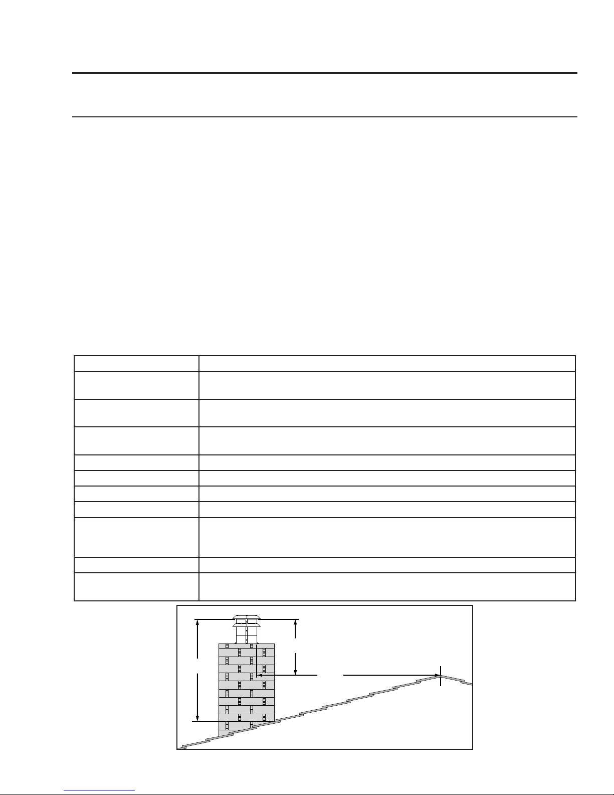
Table 4: Vent termination clearances
Minimum Clearance Description
3 ft (0.9 m)
24 in (0.6 m)
5 ft (1.5 m)
6 ft (1.83 m) Clearance to mechanical air supply inlet.
3ft (0.9m) Clearance to each side of center line extended above meter/regulator assembly.
6 ft (1.83 m) Radial clearance around service regulator vent outlet.
12 in (30 cm) Clearance above grade, verandah, porch, deck, or balcony.
3 ft (0.9 m)
9 in (0.23 m) Exception for inputs up to and including 50,000 Btu/h (15kW)
12 in (0.3 m)
Clearance above the highest point where it passes through a roof surface, refer to
Figure 23.
Clearance above a roof ridge, any other portion of a building, or any other obstruc-
tion within a horizontal distance of 10 feet (3 m), refer to Figure 23.
Clearance for a vent or chimney above either the highest connected appliance
drafthood outlet, or ue collar.
Clearance to a building opening or combustion air inlet of another appliance, ex-
cept with the approval of the authority having jurisdiction for the following reduced
clearances.
Exception for inputs exceeding 50,000 Btu/h (15kW) but not exceeding 100,000
Btu/h (30kW)
3ft (0.9m)
Minimum
21
2ft (0.6m)
Minimum
Within
10ft (3m)
Figure 23: Roof Clearances.
Roof ridge or
any other portion
of a building
Page 22
Initial Installation
QUALIFIED INSTALLERS ONLY
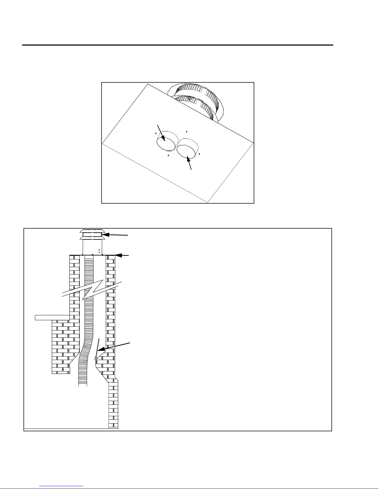
3" (76mm) Exhaust
3" (76mm) Intake
Figure 24: Generic Vent Cap Underside.
The height for the vent must be between 8 ft (2.44 m) and 30 ft (9.14 m).
Install a sealed vent cap to prevent leakage of room air up through
chimney.
The intake and the exhaust are 3" (76mm).
Measure the height of the chimney beforehand and purchase the
appropriate venting. Never attempt to over-stretch a flexible liner to
accommodate the height of the chimney. Every joint in the venting must
be secured with three (3) #8 x 3/8” HWH sheet metal screws and an
appropriate sealant (either silicone or stove cement).
The flue damper can be fully blocked open or removed for installation of
the E30GI; the smoke shelves, shields and baffles may be removed if
attached by mechanical fasteners.
The fireplace and fireplace chimney must be clean, in good working order
and constructed of non-combustible materials.
Make sure that all chimney cleanouts are tight fitting and will not permit
air to leak into the chimney.
Refractory, glass doors, screen rails, screen mesh and log grates can be
removed from the fireplace before installing the E30GI.
Figure 25: Installation of E30GI DV .
22
Page 23

Initial Installation
QUALIFIED INSTALLERS ONLY
DiRect Vent VeRticaL Vent teRmination:
instaLLation instRuctions:
1. Plan your installation and clearances to combustibles. The E30GI may be installed and vented into
any solid fuel replace that has been installed in accordance with the National, Provincial/State and
local building codes and has been constructed of non-combustible materials. Also refer to the InItIal
InstallatIon - preparIng your e30gI For InstallatIon and clearances to combustIbles sections. Refer
to Figure 25 throughout installation.
2. Stretch the Ø3” (76mm) ex vent liners to the length needed to ensure they can be easily connected
to the vent terminals.
3. Install the ex pipe assembly up through the chimney, ensure that the pipe slides through far enough
to connect onto the vent cap.
4. Most vent caps can be installed onto chimneys with ue openings up to 16” (406mm) x 16” (406mm)
and the actual ashing is 18”x18” (refer to Figure 26). If the chimney is smaller the cap should be
trimmed down and folded over.
5. Apply a bead of stove cement sealant to the top section of the Ø3” (76mm) exhaust vent collar plate.
Slide the Ø3” (76mm) ex vent over the ue collar and secure with three (3) sheet metal screws
evenly spaced.
6. Place a bead of high temperature silicone on the intake collar of the replace, slide the Ø3” (76mm)
ex intake liner over the collar, secure the ex liner with three (3) sheet metal screws evenly spaced.
7. At the top of the chimney, apply a bead of stove cement sealant to the Ø3” (76mm) pipe of the
exhaust vent terminal (refer to Figure 24). Slide the ex liner onto the vent terminal and secure with
three (3) sheet metal screws evenly spaced.
8. Place a bead of high temperature silicone on the intake collar of the vent terminal (refer to Figure 24).
Slide the Ø3” (76mm) ex intake liner over the collar, secure the ex liner with three (3) sheet metal
screws evenly spaced.
9. Make a tight connection between the gas replace insert ue collar and the replace chimney at the
top of the chimney. Secure the vent terminal to the chimney using adequate sealant, and according
to local building codes.
APPROVED TERMINATIONS:
Trim flashing
-Simpson Dura-Vent
46DVA-VCH cap with 46DVA-GK
termination adapter
or
46DVA-CL33 termination kit
as required.
-
ICC
TM-4SVT cap with TM-CTA
termination adapter
23
18"
(457mm)
Figure 26: Generic Vent Cap Dimensions.
18"
(457mm)
Page 24
Initial Installation
QUALIFIED INSTALLERS ONLY
instaLLing the unit:
• Remove the packaging from the appliance and surround panels; check to make sure there is no
damage. Carefully check the glass door. Do not use the unit if it is damaged. In the event damage is
found, please report it to your dealer as soon as possible.
• Carefully clean the replace and ue before installing the stove. Failure to do so may result in fumes
or soot being blown into the room and may cause a re leading to death or serious injury.
1. Remove the unit from the box and remove all packaging material from the appliance.
2. Remove door. See maIntenance anD serVIce - glass Door remoVal.
3. Remove log and ember set and all wrapping material from the stove. Remove wrapping material from
log and embers and check for any damage. If damage is observed, do not use unit and contact your
local dealer.
4. Check that the chimney clean outs t properly. The ue damper must be fully blocked open or removed
for installation of the E30GI; the smoke shelves, shields and bafes may be removed if attached by
mechanical fasteners.
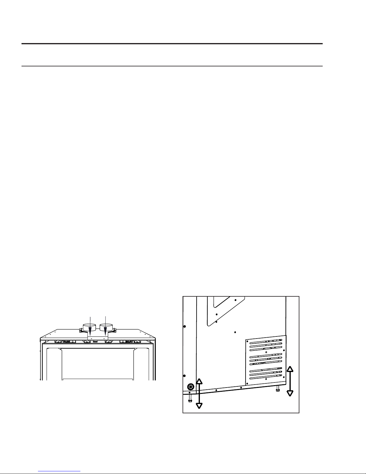
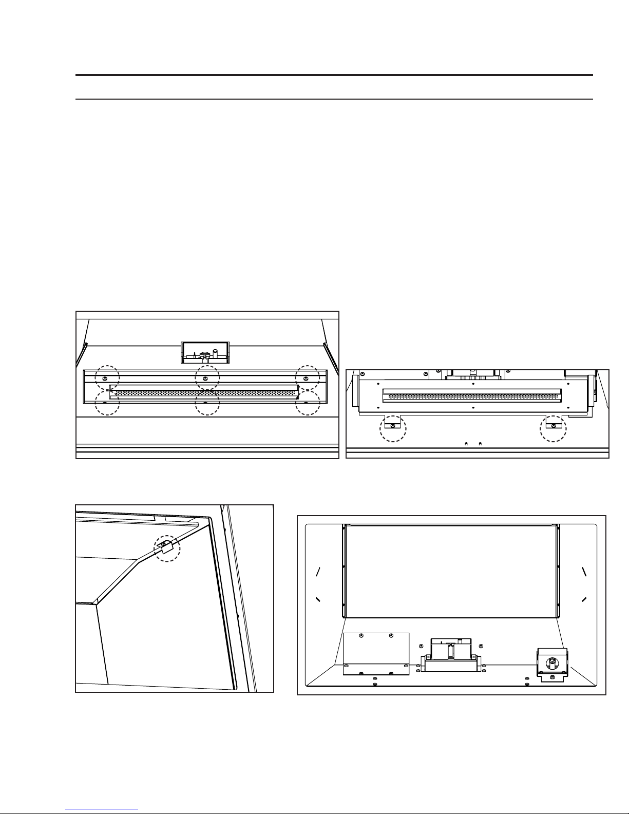
5. If the replace opening is lower than 24” (610 mm), remove the vent collar plate from the top of the
insert by unscrewing the single T-20 Torx screw located on the center top of the stove above the door
opening (see Figure 27). Slide the collar plate backwards. Properly secure the vent collar plate to the
exible vent pipe liner(s) previously installed in the chimney. Be careful not to over-stretch the liner(s).
6. Place the unit part way into the replace. Connect the gas line to the ⅜” NPT pipe nipple at the lower
left rear of the unit using locally approved methods (see InItIal InstallatIon - gas lIne connectIon).
Place the electric cable so it can be connected to the power supply.
7. As you push the unit into its nal position in the replace, if the vent collar plate was removed, reinstall
it to the stove by sliding it along the top of the unit and secure with the screw previously removed.
8. Adjust the levelling legs to ensure the unit is level and high enough if a base shelf and/or riser is to be
installed. There are four levelling legs on the bottom of the unit (shown in Figure 28).
Vent Collar
Figure 27: Vent Collar Plate Screw Location.
Screws
Figure 28: Levelling Legs Position.
24
Page 25

Initial Installation
QUALIFIED INSTALLERS ONLY
zeRo cLeaRance (zc) fiRepLace instaLLation:
The metal oor of the ZC solid fuel rebox can be removed to allow the installation of the insert. THE
CLEARANCE TO COMBUSTIBLE MATERIAL UNDER THE INSERT IS 2 1/4” (57.2 mm). YOU MUST USE
1
THE LEVELING LEGS TO RAISE THE INSERT A MINIMUM OF 2
INSTALLED ON COMBUSTIBLE MATERIAL. The optional Base Shelf and Riser are recommended to ll
the space under the unit once raised. The sidewalls and top structure of the solid fuel rebox cannot be
altered with the exception of: removal of dampers, removal of smoke shelf or bafe, removal of ember
catches, removal of log grate, removal of viewing screen/curtain, and removal of doors. THE ORIGINAL
FIREPLACE MAY NEVER BE RETURNED TO SOLID FUEL USE IN THIS CONDITION.
IMPORTANT: If the factory-built replace has no gas access hole(s) provided, an access hole of 1.5 inch
(37.5 mm) or less may be drilled through the lower sides or bottom of the rebox in a proper workmanship
like manner. This access hole must be plugged with non-combustible insulation after the gas supply line
has been installed. Cutting any sheet-metal parts of the replace, in which the gas replace insert is to
be installed, except as tested for the oor is prohibited.
The included label plate shown below must be permanently attached inside the cavity of the replace
in a visible location.
/4” (57.2 mm) IF THE UNIT IS TO BE
WARNING: This fireplace has been converted
for the use with a gas fireplace insert only and
cannot be used for burning wood or solid
fuels unless all original parts have been
replaced, and the fireplace re-approved by the
authority having jurisdiction.
Figure 29: Fireplace Altered Plate.
eLectRicaL RequiRements:
The replace must be electrically connected and grounded in accordance with local codes or, in the
absence of local codes, with the current CSA C22.1 Canadian Electrical Code Part 1, Safety Standards For
Electrical Installations, or The National Electrical Code ANSI / NFPA 70 in the US.
WARNING: The electrical grounding instructions must be followed. The fan kit is equipped with a three-
prong (grounding) plug for your protection against shock hazard, and should be plugged directly into a
properly grounded three-prong outlet. DO NOT cut or remove the grounding prong from this plug.
C-11168
CAUTION: When servicing controls, label all wires prior to disconnection. Wiring errors can cause
improper and dangerous operation. Verify proper operation after servicing.
If any of the original wire as supplied with the appliance must be replaced, it must be replaced with 18
AWG wire with a temperature rating of 105°C
25
Page 26

Initial Installation
5 of 10
QUALIFIED INSTALLERS ONLY
Figure 30: Wiring Schematic.
26
Page 27
Initial Installation
QUALIFIED INSTALLERS ONLY
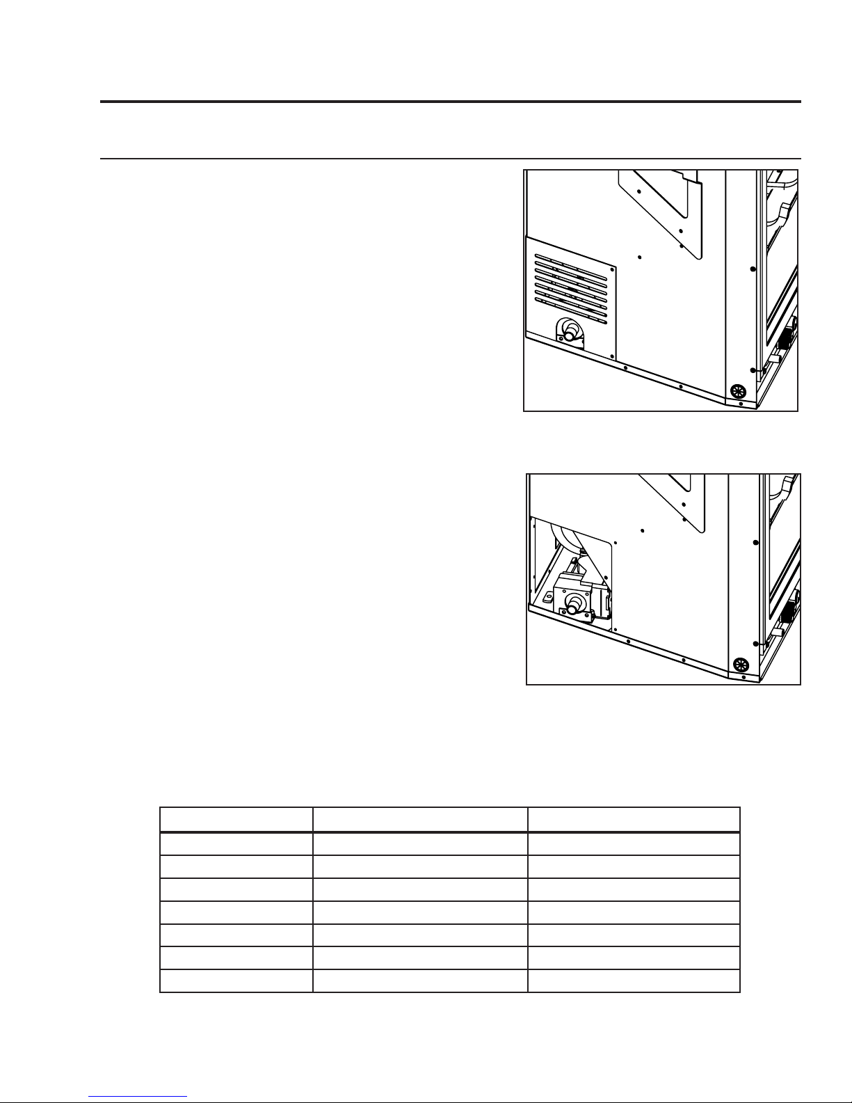
gas Line connection:
WARNING: Only persons licensed to work with gas piping
may make the necessary gas connections to this
appliance.
Gas Line Connection:
• A ⅜” 45° ared tting and ex connector are supplied with
the unit (see Figures 31 and 32). Consult the local authorities
for local codes or use the CAN/CGA B149 (1 or 2) installation
code in Canada. In the US, gas installations follow either local
codes or the current edition of the National Fuel Gas Code
ANSI Z223.1.
• If the factory-built replace has no gas access hole(s)
provided, an access hole of 1.5 in (37.5mm) or less may be
drilled through the lower sides or bottom of the rebox in a
proper workmanship like manner. This access hole must be
plugged with non-combustible insulation after the gas supply
line has been installed.
Figure 31: Gas Connection Location.
• A shut-off valve is not supplied with this unit, but one should
be installed.
• The appliance and its appliance main gas valve must be
disconnected from the gas supply piping system during any
pressure testing of that system at test pressures in excess ½
psi (3.5 kPa). The appliance must be isolated from the gas
supply piping system by closing its equipment shutoff valve
during any pressure testing of the gas supply piping system
at test pressures equal to or less than ½ psi (3.5 kPa).
Table 5: Orice and Pressure Information.
E30GI With Glass Burner & Proame Valve
Main Burner Natural Gas Propane Gas
Orice: #39 DMS #54 DMS
Max. Manifold Press: 3.8 W.C. (0.95 KPa) 11.0 W.C. (2.74 KPa)
Min. Manifold Press: 1.2 W.C. (0.30 KPa) 2.7 W.C. (0.67 KPa)
Max. Supply Press: 10.5 W.C. (2.62 KPa) 13.0 W.C. (3.24 KPa)
Min. Supply Press: 3.5 W.C. (0.87 KPa) 8.0 W.C. (1.99 KPa)
Max. Input: 33,000 BTU/hr (9.67 KW) 30,000 BTU/hr (8.79 KW)
Min. Input: 16,500 BTU/hr (4.84 KW) 15,000 BTU/hr (4.4 KW)
Figure 32: Gas Valve with Cover
Removed.
27
Page 28
Initial Installation
QUALIFIED INSTALLERS ONLY
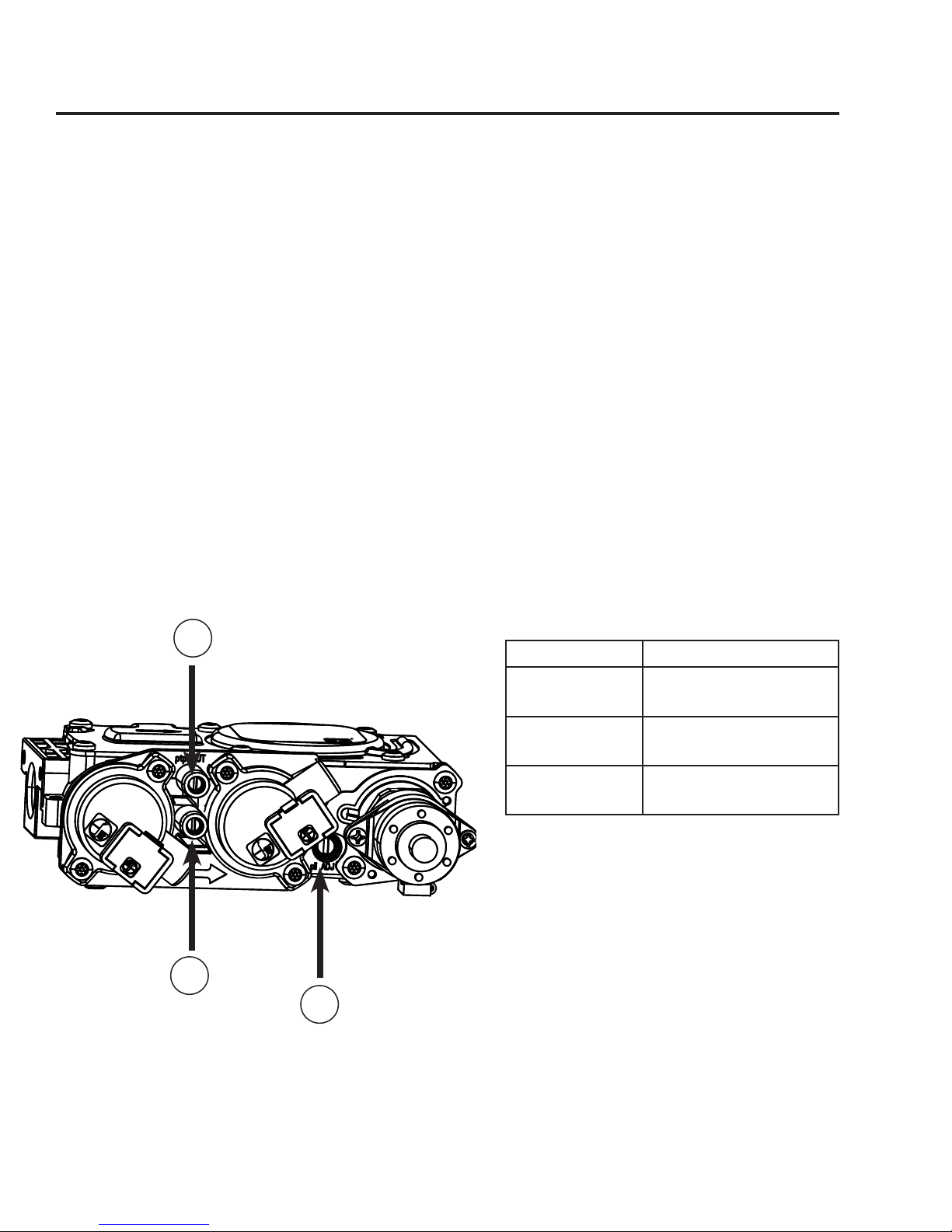
TO TEST VALVE PRESSURES (INPUT RATES):
The pressure taps are located on the front side of the valve (see Figure 33).
1. Using a long at bladed screwdriver, turn set screw counter-clockwise to loosen.
2. Place 5/16 in (8 mm) I.D. hose over the pressure taps.
3. Check pressures using a manometer.
4. When nished, remove hose and tighten set screw.
Always check for gas leaks with a soap and water solution after completing the required
pressure test.
NEVER USE AN OPEN FLAME FOR LEAK TESTING.
3
2
1
Figure 33: Valve Details.
Item number DescrIptIon
1 Pilot Adjustment
Screw
2 Inlet Pressure Test
Point
3 Outlet Pressure Test
Point
Table 6: Valve Details.
28
Page 29

Initial Installation
QUALIFIED INSTALLERS ONLY
aDjusting the piLot fLame:
The pilot ow adjustment is set to maximum at the factory and should not need to be adjusted. The pilot
ame should envelope ⅜” to ½” (10 to 13mm) of the ame sensor (see Figure 34). However, should the
need arise, follow Steps 1- 2 below.
1. The adjustment screw can be reached through the front of the unit using a 10 inch long blade head
screw driver (see Figure 33 for location on valve).
2. Turn the adjustment screw clockwise to decrease or counterclockwise to increase pilot ame.
Flame Sensor
.375
-.500
(10-13mm)
Figure 34: Proper Pilot Flame.
29
Page 30
Secondary Installation
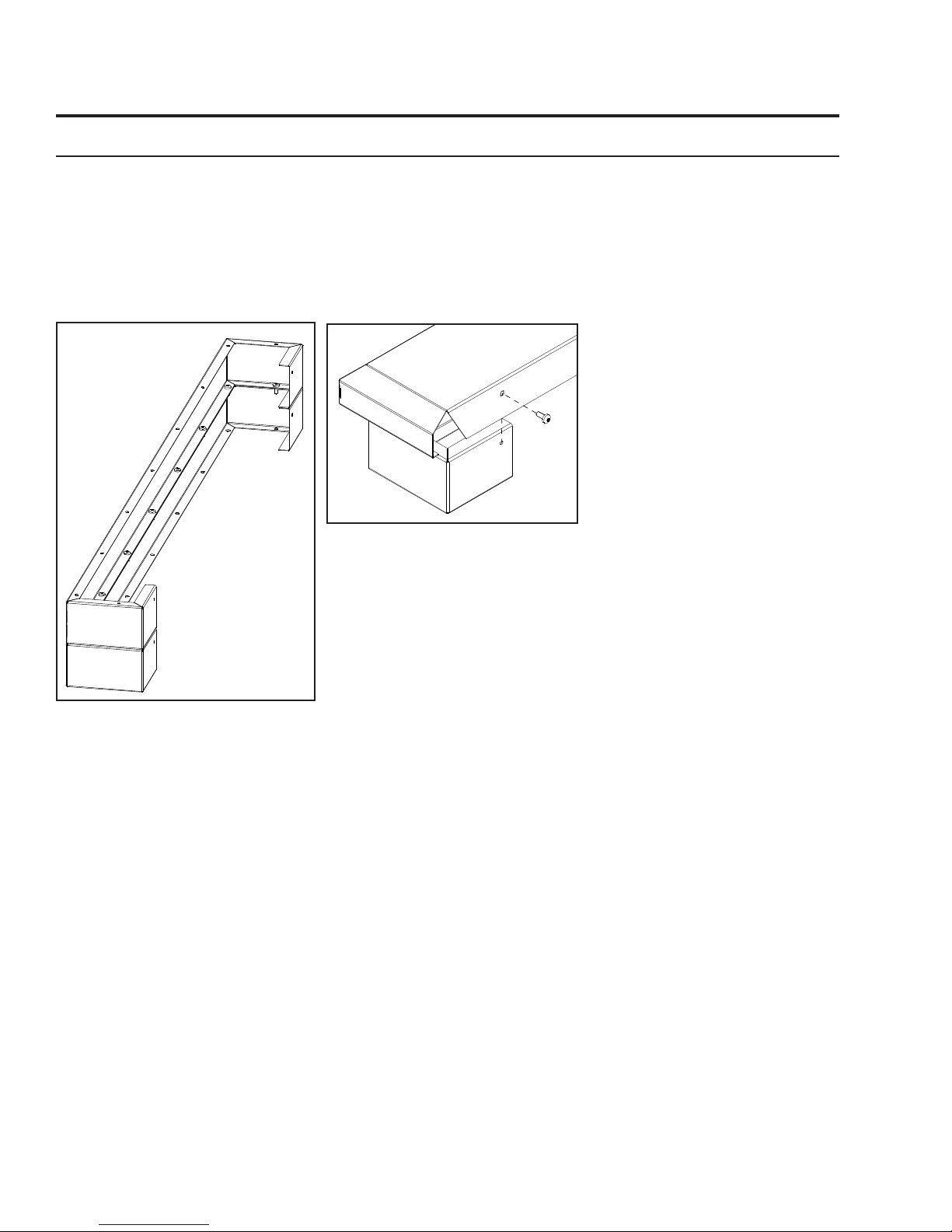
optionaL base sheLf & RiseR:
The E30GI Base Shelf (1⅝” (41 mm) high) and Base Shelf Riser (2⅛” (54 mm) high) are components
that can be combined to create a riser with an overall height of 23/16” (55 mm). This shelf can be installed
with or without the riser and can be used when the hearth in front of the unit is lower than the replace
opening. Additional Base Shelf Risers can be fastened together to increase the height in increments of
2⅛” (54 mm). This Base Shelf may be used in conjunction with the any of the E30GI surround panel
options, and it may also be used with the E30GI Trimmable Surround. The Base Shelf and Riser are sold
separately.
Installation:
1. If unit is running, turn it off and
allow it to cool completely.
2. When using more than one riser
each level must be attached
using nine (9) #8 T-20 screws
provided (see Figure 35).
3. If installing with riser(s) the
Base Shelf is to be fastened
Figure 36: Installing Base Shelf
onto Riser.
4. The leveling legs on the E30GI may need to be adjusted to match
the height of the riser and shelf.
5. Center the Base Shelf assembly in front of the unit ush with the
bottom of the unit.
6. Install surround if required.
to the riser(s) with one T-20
screw at each end of the back
(see Figure 36).
Figure 35: Combining 2 Base Shelf
Riser.
30
Page 31

Secondary Installation
ReDuceD Depth:
The extension brackets installed on the outside of the stove are used to make the front of the surround panel
ush with the safety screen. If the regular depth is required, skip to page 34. If the reduced install depth is
required, the top and side extensions will need to be removed and the hardware re-located as outlined in
steps 1-5 below:
Top Cabinet
REMOVAL:
1. Using a T20 screwdriver,
remove the four (4) scrrews
that secure the Top Extension
to the Cabinet (see Figure 38).
2. Remove the four (4) screws
on each Side Extension (see
Figure 38).
Step 3-5 on next page
Extension
Side Cabinet
Extensions
31
Figure 37: Stove as Shipped
A
Figure 38: Removing Extension Screws.
Page 32

Secondary Installation
smaLLeR Depth:
1. Remove the four (4) screws
from the outside of the Right
Side Extension (see Figure 39).
2. Repeat for Left Side Extension.
3. Install three (3) screws halfway
into the Cabinet as shown in
Figure 41.
Figure 40: Screw Install Depth.
Figure 39: Removing Extension Screws.
NOTE: The screws may need
to be adjusted to t with the
safety screen.
Figure 41: Reinstalling Screws.
32
Page 33
Secondary Installation
optionaL 3 anD 4 siDeD tRimmabLe paneLs:
Modifying the Surround Panel:
The E30 Trimmable Surround Panels are large rectangular panels that may be cut for use in cases that a nonstandard replace opening (e.g. an arched opening) is to be lled. Optionally this surround can be left uncut
and placed in front of the replace opening.
1. Measure the replace opening and/or make a template of the replace opening.
2. Transfer the measurement to the Trimmable Surround.
3. If desired, offset the measurements by approximately
to be placed just inside the replace opening for a cleaner appearance.
4. Cut along the preferred line (from direct measurements of offset) and remove any sharp edges.
5. The panel can be touched up with a high temperature metallic black paint available from your dealer.
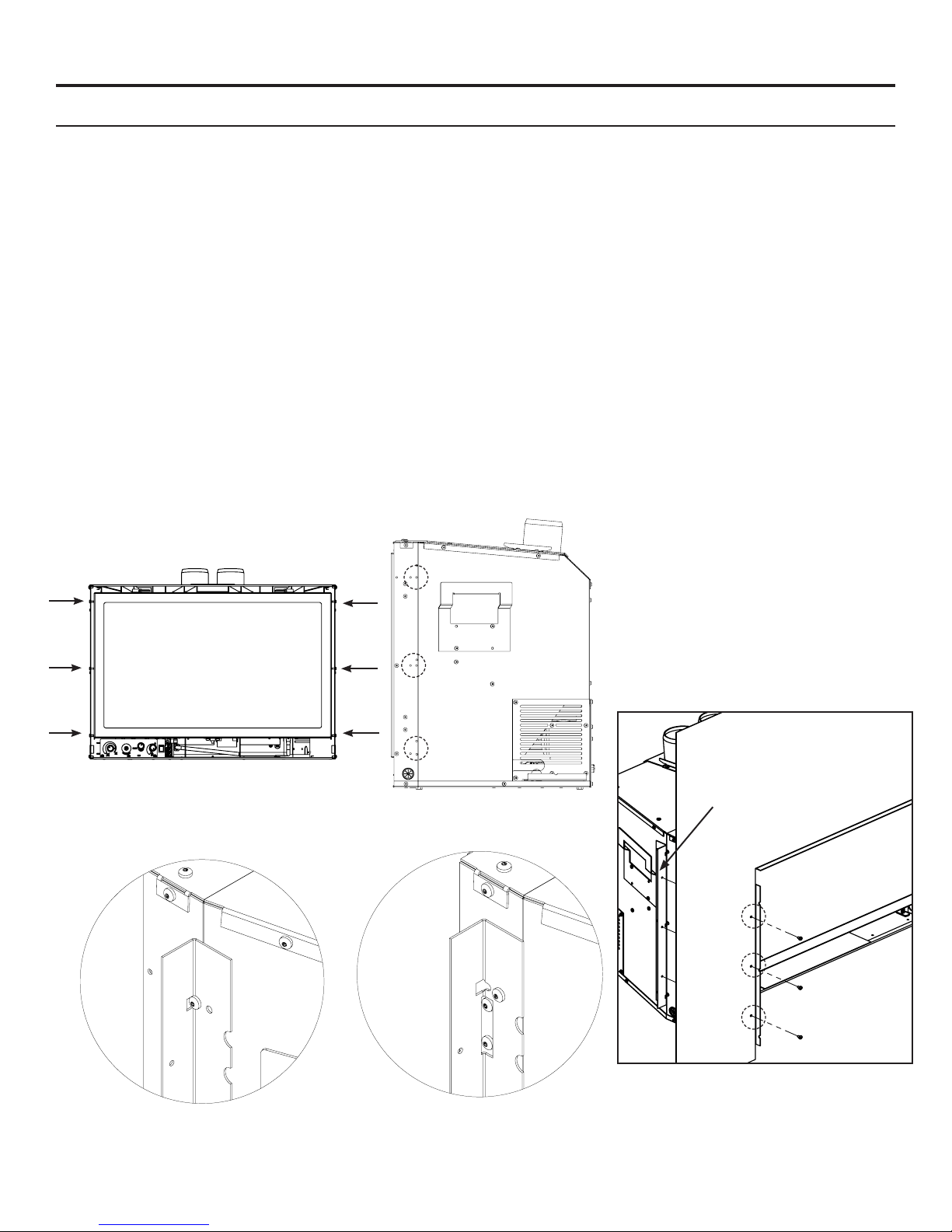
REDUCED DEPTH INSTALLATION:
1. Install the two Trimmable Panel brackets onto the E30 unit using a T-20 Torx screwdriver. See Figures 42
and 43 for the screw installation locations. There are three sets of hole patterns on the brackets depending on
which Surround Panel is being installed. See Figures 42-46.
1
/8” (3mm) to the inside; this will allow for the panel
NOTE: The Extruded and
Contemporary Surround Panels use
the same holes for mounting the
Trimmable Brackets. The Regular
Surround Panel uses its own set of
holes.
Figure 42: Screw
Installation Locations.
Figure 43: Screw
Installation Locations.
Installed Brackets
Figure 44: Installation for Contemporary
and Extruded Surround.
33
Figure 46: Screw
Installation Locations.
Figure 45: Installation
for Regular Surround.
Page 34
Secondary Installation
optionaL 3 anD 4 siDeD tRimmabLe paneLs:
Modifying the Surround Panel:
The E30 Trimmable Surround Panels are large rectangular panels that may be cut for use in cases that a nonstandard replace opening (e.g. an arched opening) is to be lled. Optionally this surround can be left uncut
and placed in front of the replace opening.
1. Measure the replace opening and/or make a template of the replace opening.
2. Transfer the measurement to the Trimmable Surround.
3. If desired, offset the measurements by approximately
to be placed just inside the replace opening for a cleaner appearance.
4. Cut along the preferred line (from direct measurements of offset) and remove any sharp edges.
5. The panel can be touched up with a high temperature metallic black paint available from your dealer.
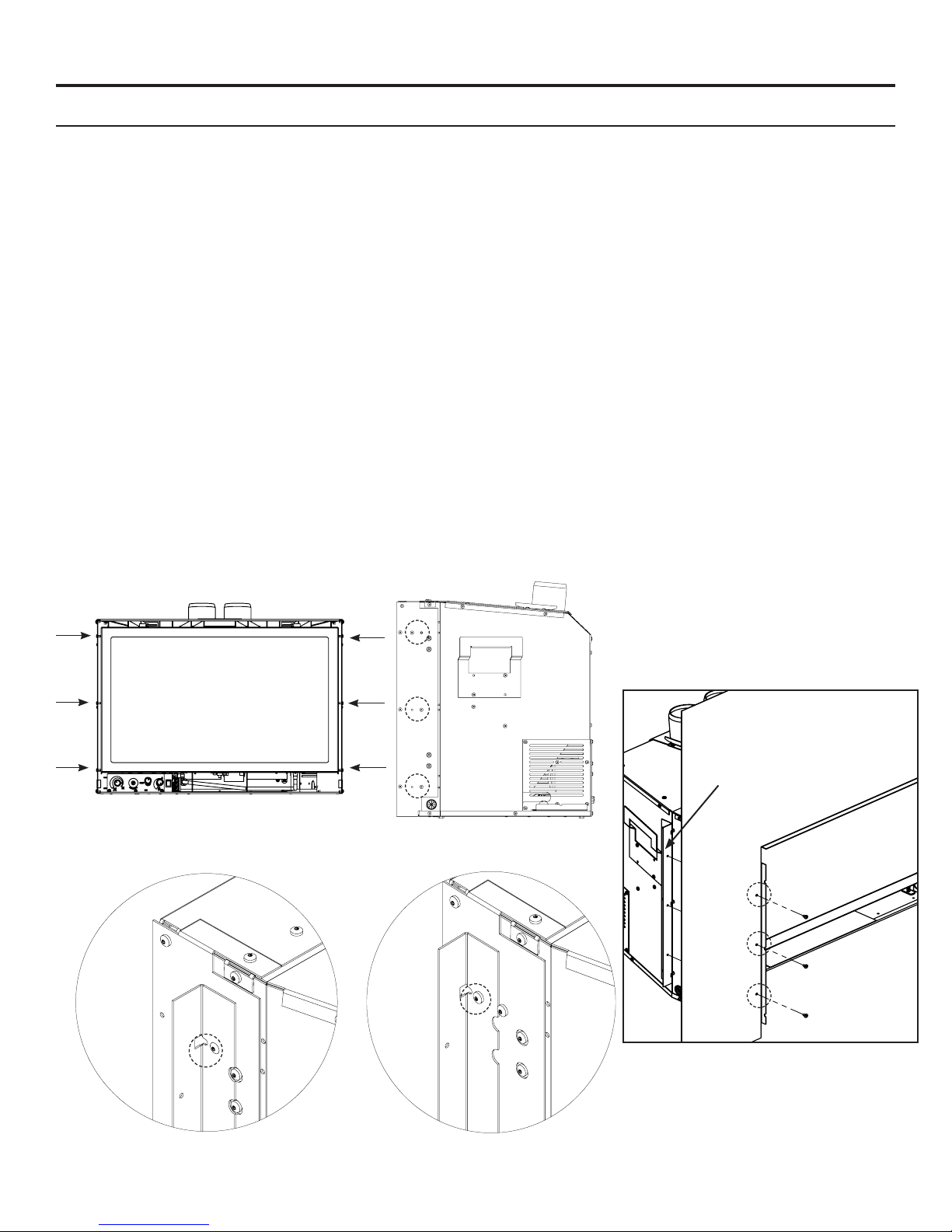
REGULAR DEPTH INSTALLATION:
1. Install the two Trimmable Panel brackets onto the E30 unit using a T-20 Torx screwdriver. See Figures 46
and 47 for the screw installation locations. There are three sets of hole patterns on the brackets depending on
which Surround Panel is being installed. See Figures 47-51.
1
/8” (3mm) to the inside; this will allow for the panel
NOTE: The Extruded and Contemporary Surround Panels use the same holes for mounting the Side Cabinet
Extensions. The Regular Surround Panel uses its own set of holes.
Installed Brackets
Figure 47: Screw
Installation Locations.
Figure 48: Screw
Installation Locations.
Figure 49: Installation for Contemporary
and Extruded Surround.
34
Figure 51: Screw
Installation Locations.
Figure 50: Installation
for Regular Surround.
Page 35

Secondary Installation
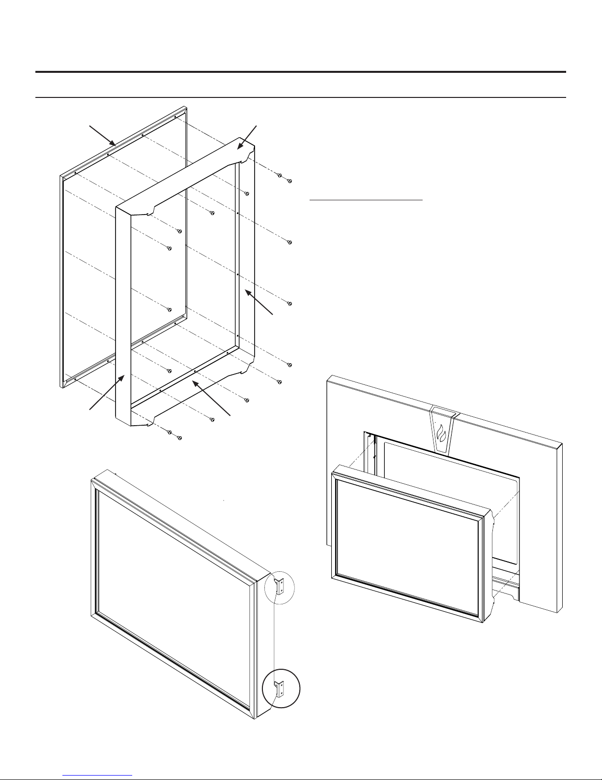
suRRounD paneL instaLLation:
WARNING: The surround becomes hot when the unit is operating; ensure that the unit is turned off, and that
it has cooled to room temperature before beginning this installation.
Height Width
7
3-Sided Surround 25” (635 mm) 39
1
4-Sided Surround 31
Table 7: Surround Dimensions.
Please check components supplied with this kit. If components are missing or have been damaged, contact your
dealer, distributor or courier company before starting this installation.
IMPORTANT: The panel must not seal ventilation openings in the replace.
INSTALLATION (3 and 4 sided Surrounds):
Lift the face upright in front of the replace with the six hooks pointing towards the replace. Slide the hooks
over their corresponding screws (see Figures 52 & 53). Ensure the hooks are secure before releasing the
surround. The surround should be wiped with a damp cloth periodically. Screws can be tightened for a more
permanent install.
/2” (800 mm) 39 7/8” (1013 mm)
/8” (1013 mm)
REMOVAL:
Lift the surround straight up in order to unhook the notch on the hooks from the screws. Pull the surround away
from the replace. Place the surround where it will not be damaged.
Access Panel
removed for
clarity.
Figure 52: Screw Locations. Figure 53: Screw and Hook Close-Up.
BURNER SWITCH WIRING INSTALLATION:
The burner switch supplied with the surround comes pre-installed and wired. The wiring from the burner switch
simply needs to be connected to the wiring on the E30 unit.
The wiring harness for the burner switch has one (1) blue wire, one (1) grey wire and two (2) purple wires.
The blue wire connects to the blue wire on the E30 unit, the grey wire connects to the grey wire on the E30 unit,
and the purple wires are used to connect an optional thermostat.
CLEANING:
Painted surfaces should be periodically wiped with a damp cloth. Never clean the face when it is hot.
35
Page 36
Secondary Installation
A
DETAIL A
SCALE 3 : 1
safety scReen instaLLation:
Safety Screen Frame
Right Bracket
Top/Bottom
Bracket
The safety screen supplied with the unit must be
assembled rst before it can be installed. When
installed, the screen should not extrude out any farther
than the surround panel if the cabinet extensions are
still installed.
Safety Screen Assembly
1. Attach the left, right, top/bottom brackets onto
the safety screen using a T20 screwdriver and the
supplied sixteen (16) #8 T20 screws (see Figure
54). Do not over-tighten the screws, doing so
could cause them to strip out of the screen frame.
2. Lift the face upright in front of the replace with
the four (4) hooks pointing towards the replace.
Slide the hooks into the corresponding brackets
on each side of the cabinet (see Figure 56).
Ensure the hooks are secure before releasing the
safety screen.
Top/Bottom
Bracket
Figure 54: Installing Safety Screen Mounts.
Left Bracket
Figure 55: Installing Safety Screen onto
Brackets.
Figure 56: Installing Safety Screen onto
Cabinet Bracket (Parts removed for clarity)
Page 37
Secondary Installation
fiRebox LineR anD buRneR tRay RemoVaL/instaLLation:
NOTE: The porcelain on the rebox liners is fragile and should be handled gently.
WARNING: Failure to position the parts in accordance with these diagrams or failure to use only parts
specically approved with this appliance may result in property damage or personal injury.
1. Ensure the E30GI is turned off and allow the unit to cool.
2. Remove the glass door as shown in the
WARNING: Do not touch or attempt to remove the glass if the replace is not completely cool.
Never operate the replace with the glass removed.
3. Remove the glass material (if installed).
4. Use the following steps to remove the liners and the burner tray.
NOTE: Follow the steps in the reverse order for reassembly.
maIntenance anD serVIce - glass Door remoVal.
Figure 56: Remove the six T20 screws and then
remove the bottom panel by lifting up.
Figure 58: Remove the clips which
secure the side panels and then pull the
bottom of the panels towards the center
of the rebox.
Figure 57: Remove the two T20 screws holding
the burner tray down. Gently pull the assembly
out of the venturi box
Figure 59: Remove the rear brick panel by pulling
it forward off the ledge.
37
Page 38

Secondary Installation
instaLLing the gLass beaDs:
Pour the glass beads into the tray and evenly distribute over the entire tray.
Ensure that the pilot box remains clear of any glass.
Figure 60: Burner tray with glass installed.
38
Page 39

TroubleShooting
Diagnostic fLash coDes:
1. Fail to ignite: If there is no positive ignition, the board will go into lock out and the LED will blink 3 times
in intervals until the system is reset.
2. Low battery condition (<4V): the LED indicator will blink one (1) time in intervals.
3. Parasitic Pilot Flame: the LED indicator will blink two (2) times in intervals.
4. System Lock out: the LED indicator will blink three (3) times in intervals.
Additional Ignition Information
1. The Proame DFC Board will try two (2) times for ignition.
2. Each try for ignition will last approximately 60 seconds.
3. The wait time between the two tries is approximately 35 seconds.
Figure 61: Proame DFC Board with LED Indicator attached.
39
Page 40

TroubleShooting
Problem Possible Cause Solution
Thermostat
does not
work
No spark
generation
No pilot
ame ignition
The pilot ame has gone out
The On/Off switch is turn to OFF
The thermostat is set too high
Spark developes near the pilot
assembly or could occur onboard
No spark from the igniter
Air in the gas line
Pilot gas pressure dropout upon
main burner gas valve opening
No gas ow out of the pilot burner
· Turn it ON
· Set the thermostat to a lower temperature
· Check pilot assembly wiring
· Check for broken or poor connection from the sparker to the
electrode
· Check for the spark shorting or arcing at other locations
· Check for defective sparker and spark electrode
· See “no spark generation”
· It takes a while for all the air to purge out of the pilot before gas
can reach the pilot and ignite
· Check gas mains supply and pressure
· Check gas valve wirings and connections to the board
· Check the pilot burner for obstruction
· Check the wirings and connections between the pilot assembly and
the board
· Check the correct gas type settings on the valve and pilot burner
assembly orice
Pilot will not
remain lit
Remote
control does
not work
No reaction
to command
Problem with Flame Sensor circuit
Restrictor setting
The pilot light has gone out
The remote is too far away from
the heater
The remote control receiver is
turned “OFF”
One of the two remote control or
receiver batteries are dead
Receiver or transmitter batteries
are low
A maximum number of failed
ignitions or ame restorations have
been reached.
· Check for proper connection of the Flame Sensor to the DFC board
· Check pilot for full ame impingement around Flame Sensor
· If ame is too small, check gas pressure, adjust pilot rate screw,
check pilot head for damage
· Ensure the ground wire is properly attached to the pilot mounting
bracket and that it is makes a good electrical connection.
· Use the correct restrictor setting for the venting conguration
· See “Pilot will not remain lit”
· Use the remote closer to the heater
· Check the remote control instructions
· Replace the batteries
· Replace the batteries
· Remove any possible blocking conditions. See “locking conditions”
· See how to reset the board from Lockout
No communication between the
remote control and the receiver
· Reprogram the transmitter to the receiver.
· Follow the initializing system for the rst time
40
Page 41

TroubleShooting
Problem Possible Cause Solution
· Turn the system off by pressing the ON/OFF button on
the transmitter
· After approximately 2 seconds press the ON/OFF button
on the transmitter again.
· In the manual ame control mode, use the down arrow
button to reduce the ame to off, indicated by the word
Locking
conditions
Main burners
will not start
Reset the Proame DFC board
The pilot ame has gone out · See “Pilot will not remain lit”
The remote control is not working
correctly
The thermostat is disconnected or
set too high
Problem with thermopile circuit
OFF displayed on the transmitter LCD screen.
· Wait approximately 2 seconds and press the up arrow
button, the ignition sequence will start.
· With the transmitter off, move the slider switch on the
receiver to the OFF position.
· Wait approximately 2 seconds and move the receiver
slider switch to the ON position.
· Replace the batteries
· Set the thermostat to a lower temperature
· Check gas line pressure
· Check wiring to thermostat for breaks
· Check for ame impingement on thermopile
Flame lifting
Blue Flames
Glass fogs up
Flames are
burning
“dirty” or
sooting
Leak in vent pipe · Check for leaks in vent connections
Improper vent conguration
Terminal may be re-circulating ue
gases
The heater has just been started
Improper air shutter adjustment · Adjust air shutter – contact your dealer
Normal condition: after the
appliance warms up the glass will
be clear.
The logs or glasses are placed
incorrectly
Improper air shutter adjustment
Incorrect rating input
· Check vent conguration with manual
· Check to see if terminal is on correctly
· May need to install high wind termination cap.
· Contact dealer
· Normal during start up: ame will yellow as the replace
heats up
**Due to additives in gas, glass may get hazy during
operation** Clean as needed.
· Check log positioning
· Check level of glasses layout
· Increase primary air by opening the air shutter and/or
by opening the vent restrictor
· Check for proper venting and blockage of the vent
termination
· See also “Burners will not remain lit”
· Check manifold pressure and clock input rating for overring
41
Page 42

Parts List
Reference
Number
1 DV Flue Adaptor Bottom Gasket 50-2497
2 Door Release Tool 50-2510
3 Domestic Power Cord (115V) EC-042
4 Heyco Strain Relief EC-044
5 E30GI Pilot Shield 50-2550
6 FPI Fan Controller (69.5V) 115V W/FS Knob EF-045
7 Fan Controller Knob W/Decal EC-040
8 Burner Tray 50-2551
9 Door Complete 50-2505
10 Glass C/W Gasket (21.75” X 13.575”) 50-2506
11 Dual Bulb Door Gasket (10ft) 50-634
12 Valve Cover with Gasket 50-2503
13 Fan Only 50-2493
14 Pilot Gasket EC-021
15 Door Latch Mechanism (Set of 2) 50-2507
16 120 Ceramic Fan Temp Sensor EC-001
17 885 Proame IPI Valve NG 50-2682
18 Burner Control Module 50-2781
19 PSE IPI Pilot Assembly 50-3026
20 Remote Receiver 50-2007
- E30GI Owners Manual 50-2581
- E30GI Conversion Kit NG to LP 50-2487
- E30GI Conversion Kit LP to NG 50-2542
- Porcelain Liner Set 50-2427
- 12 oz. Can of Metallic Black Touch Up Paint PAINT-12-MB
- Blank Filler Switch EG30-010
- Remote Transmitter 50-2411
- Wire Harness - Receiver 50-2008
- Wire Harness - IPI 50-2009
Part Description Part Number
42
Page 43
Parts List
Reference
Number
21 Regular Surround Panel 50-2418
22 Contemporary Surround Panel 50-2419
23 Extruded Surround Panel 50-2420
24 Trim-able Surround Panel 50-2422
25 Base Shelf 50-2424
26 Base Shelf Riser 50-2425
27 Four Sided Surround 50-2484
28 Four Sided Trimmable Panel 50-2485
29 Safety Screen 50-2495
- Oversized Contemporary Surround Panel 50-2558
- Oversized Extruded Surround Panel 50-2559
Option Description Part Number
43
Page 44

Parts Diagram - Components
9
10
11
18
20
8
15
1
2
13
14
5
17
19
7
6
3
4
12
16
44
Page 45
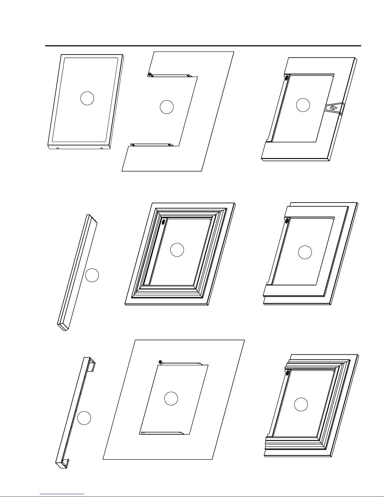
Parts Diagram - Options
29
24
21
27
28
26
25
22
23
45
Page 46

NOTES
46
Page 47
Dec 2014
Sher wood Industries Ltd. (“Sherwood”) hereby warrants, subject to the terms and
conditions herein set forth, this product against defects in material and workmanship
during the specified warranty period starting from the date of original purchase at retail.
In the event of a defect of material or workmanship during the specified warranty period,
Sherwood reserves the right to make repairs or to assess the replacement of a defective
product at Sherwood’s factory. The shipping costs are to be paid by the consumer.
All warranties by Sherwood are set forth herein and no claim shall be made against
Sherwood on any oral warranty or representation.
Conditions
A completed warranty registration must be submitted to Sherwood within 90 days
of original purchase via the online warranty registration page or via the mail-in
warranty registration card provided. Have the installer fill in the installation data
sheet in the back of the manual for warranty and future reference.
This warranty applies only to the original owner in the original location from date of
install.
The unit must have been properly installed by a qualified technician or installer, and
must meet all local and national building code requirements.
The warranty does not cover removal and re-installation costs.
Sherwood Industries Ltd. reserves the right to make changes without notice.
Sherwood Industries Ltd. and its employees or representatives will not assume
any damages, either directly or indirectly caused by improper usage, operation,
installation, servicing or maintenance of this appliance.
A proof of original purchase must be provided by you or the dealer including serial
number.
This warranty does not cover any discoloration of the safety screen mesh.
Exclusions
An expanded list of exclusions is available at www.enviro.com/help/warranty.html
This warranty does not cover:
Damage as a result of improper usage or abuse.
Damage caused from over-firing due to incorrect setup or tampering.
Damage caused by incorrect installation.
To the Dealer
Provide name, address and telephone number of purchaser and date of purchase.
Provide date of purchase. Name of installer and dealer. Serial number of the
appliance. Nature of complaint, defects or malfunction, description and part # of any
parts replaced.
Pictures or return of damaged or defective product may be required.
To the Distributor
Sign and verify that work and information are correct.
Sherwood Industries Ltd.
6782 Oldfield Road, Victoria, BC . Canada V8M 2A3
Online warranty registration: www.enviro.com/warranty/
Warranty for Enviro Gas Products
Category One Year Two Year Limited Lifetime (7yr)
Parts
1
(unit seria l numbe r requi red)
Firebox Liner Panels
(excluding porcelain)
Ceramic Steel
Firebox
Heat Exchanger
Burner
Ceramic Logs
2
Ceramic Glass
3
Pedestal / Legs
(excluding finish)
Door Assembly
Surround Panels
(excluding finish)
Exterior Panels
(excluding finish)
Up to 5 years
Electrical Components
Exterior Surface Finishing
4
Labour
1
Whereas warranty has expired, replacement parts will be warrantied for 90 days from part purchase date. Labour not included.
Unit serial number required.
2
Log set and panels excludes wear and tear or breakage caused by cleaning or service.
3
Glass is covered for thermal breakage. Photos of box, inside of door, and unit serial # must be supplied for breakage due to shipping.
4
Exterior Surface finishing covers plating, enamel or paint and excludes colour changes, chipping, and fingerprints.
Travel costs not included.
47
Page 48

Installation Data Sheet
The following information must be recorded by the installer for warranty purposes and future reference.
NAME OF OWNER:
_________________________________________
ADDRESS:
_________________________________________
_________________________________________
_________________________________________
PHONE:___________________________________
MODEL:___________________________________
SERIAL NUMBER:___________________________
DATE OF PURCHASE: _____________ (dd/mm/yyyy)
NAME OF DEALER:
_________________________________________
ADDRESS:
_________________________________________
_________________________________________
_________________________________________
PHONE:___________________________________
NAME OF INSTALLER:
_________________________________________
DATE OF INSTALLATION:___________(dd/mm/yyyy)
� DIRECT VENT � B-VENT
� NATURAL GAS (NAT) � PROPANE(LPG)
INLET GAS PRESSURE:_________in WC
MAIN BURNER ORIFICE:__________# DMS
PILOT ORIFICE #_________OR________in diam.
INSTALLER’S SIGNATURE:
_________________________________________
MANUFACTURED BY:
SHERWOOD INDUSTRIES LTD.
6782 OLDFIELD RD. SAANICHTON, BC, CANADA V8M 2A3
www.enviro.com
December 11, 2014
ADDRESS:
_________________________________________
_________________________________________
_________________________________________
PHONE:___________________________________
C-14469
48
 Loading...