

Enviro C34, C60, C44 Instruction Manual
PLEASE KEEP THESE INSTRUCTIONS FOR FUTURE REFERENCE
C Series
HEAT DISTRIBUTION / TV KIT
N A T U R A L L Y V E N T E D [ 5 0 - 3 3 9 5 ]
INSTRUCTION MANUAL
This Heat Distribution Kit has been tested for compliance to Standards:
This Heat Distribution Kit has been approved for use on the ENVIRO C34/44/60 Direct Vent
replaces only and must be installed at the time of replace installation.
The following instructions must be followed in conjunction with the replace installation
4001609
Version Française: www.enviro.com/fr.html
instructions to comply with the standards and allow safe operation of the installed replace.
ANSI Z21.88-2014 and CSA Z2.33-2014.
50-3306
1
4
5
2
3
6
General Information
7
5
8
"
(19.4 cm)
45" (114.3 cm)
31
3
4
" (80.6 cm)
25" (63.5 cm)
5" Vent Collars
40" (101.6 cm)
9
3
8
"
(23.8 cm)
2
3
4
" (7 cm) Standoff
2
1
2
" (6.6 cm) Standoff
11
7
8
"
(30.2 cm)
7
3
8
"
(18.7 cm)
2
1
8
"
(5.4 cm)
1
2
"
(1.3 cm)
3
1
2
" (8.9 cm)
2
5
8
" (6.7 cm)
The purpose of this optional Heat Distribution Kit, or HDK, is to naturally re-direct the convective heat from
the replace. Using this HDK lowers the temperatures of the front wall for installations where a TV, artwork
etc. is desired directly above the
replace. The outlet of the HDK can be
raised higher up the front wall, within
4” of the room’s ceiling, or ducted into a
different room for a cleaner front wall.
Note: Dual Convection Fan Kit
(50-3212) may not be used in
conjunction with HDK.
Prior to installation of the HDK make
sure the desired location is large
enough to comply with the combustible
clearances of both the HDK and the
replace (see Owner’s Manual for
replace installation instructions). Refer
to the
this manual for the required installation
dimensions of the HDK.
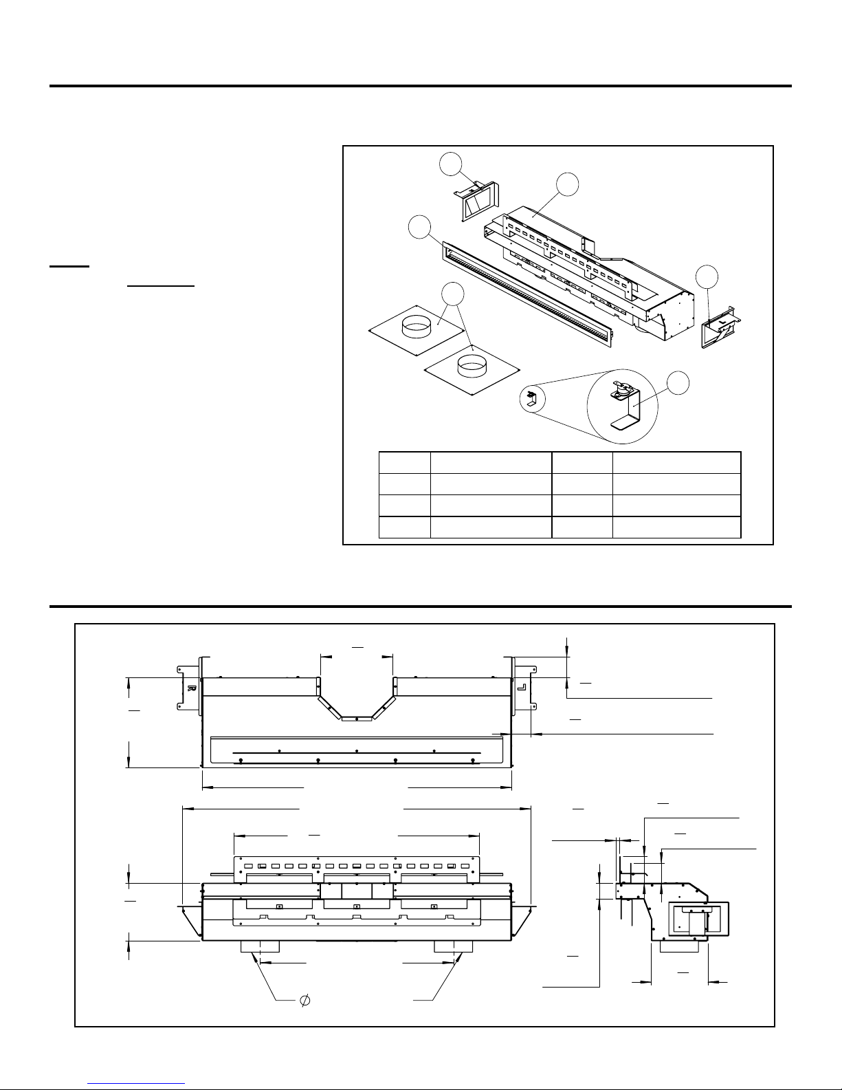
Please refer to Figure 1 to ensure that all
HDK parts are accounted for and have
not been damaged.
Framing and ClearanCes section of
Item Description Item Description
1 Main Duct Body 4 Outlet Trim Bezel
2 Right Standoff 5 Vent Collars
3 Left Standoff 6 Hi-Limit Switch
Figure 1. Heat Distribution Kit - Parts Diagram
Dimensions
Figure 2. Heat Distribution Kit - Overall Dimensions
2
7 1/2"
(2.5 cm)
45" (114 cm)
37 1/4"
(94.6 cm)
Min.
Height
2 x 4 (On Edge)
2 x 4 (On Edge)
Steel Stud
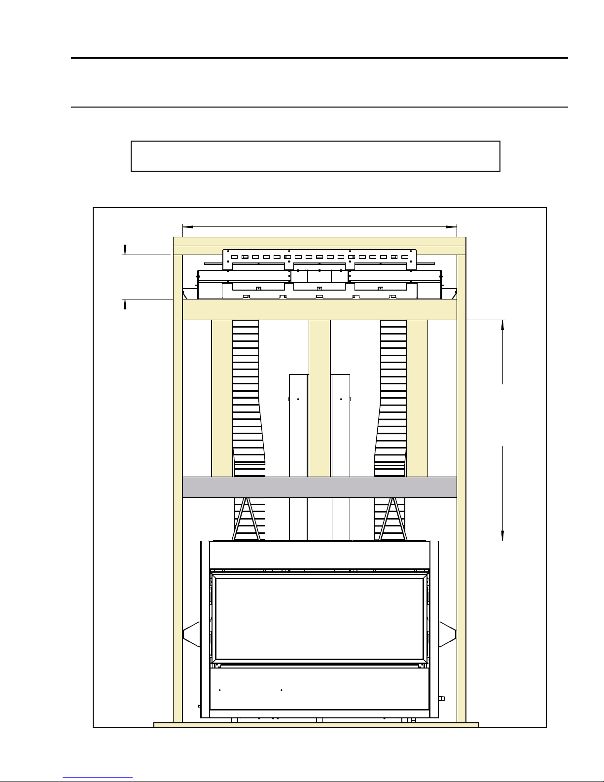
Framing & Clearances
QUALIFIED INSTALLERS ONLY
Framing & rough opening:
Refer to Figures 3 & 4 for the minimum allowable framing and rough opening of the HDK.
HDK Outlet Min. Top and Bottom standoff = 2⅝” (6.7 cm) *All C Series*
C34
3
Figure 3. C34 - HDK Framing & Rough Opening
7 1/2"
(2.5 cm)
45" (114 cm)
Steel Stud
2 x 4 (On Edge)
2 x 4 (On Edge)
37 1/4"
(94.6 cm)
Min.
Height
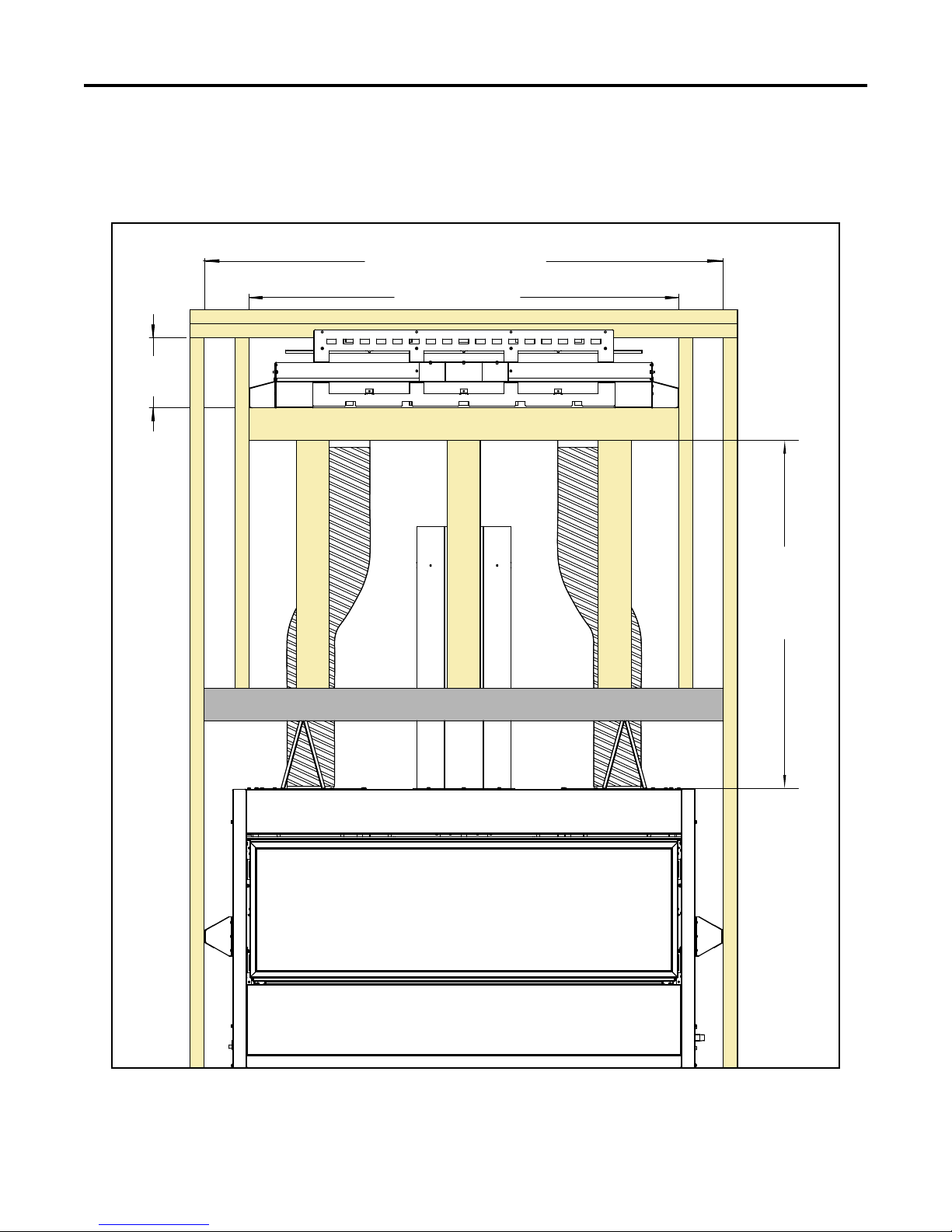
C60 = 71" (180 cm)
C44 = 55" (140 cm)
Framing & Clearances
QUALIFIED INSTALLERS ONLY
C44 & C60
Figure 4. C44/60 - HDK Framing & Rough Opening
4
Framing & Clearances
5
5
8
" (14.3 cm)
4" (10.2 cm)
2
3
4
" (69.8 cm)
73
1
4
"
(174.9 cm)
Side Brace
Min. Height
20" (50.8 cm)
Min. Depth
QUALIFIED INSTALLERS ONLY
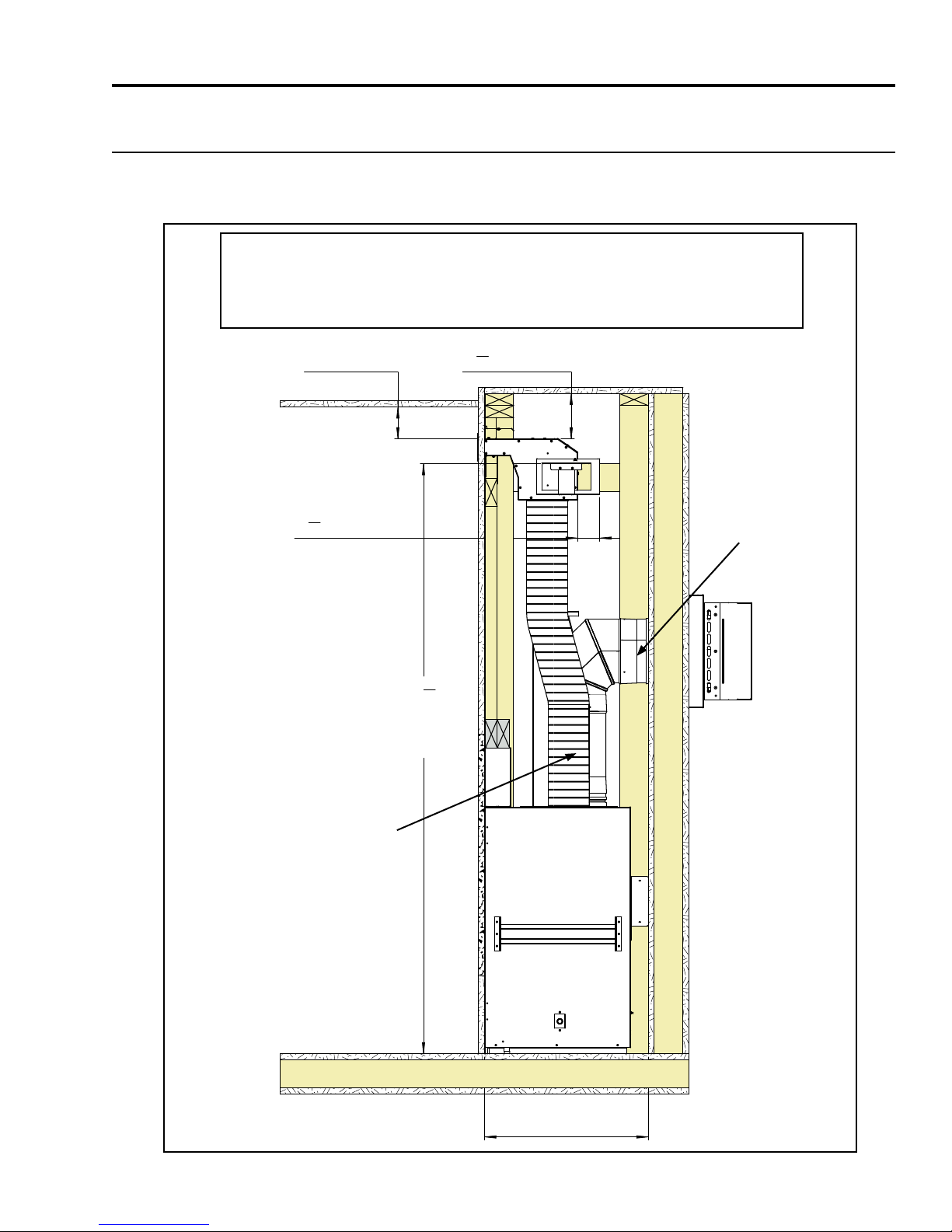
minimum ClearanCes - minimum vent:
Shown below in Figure 5 are the minimum framing and clearances for the HDK when the replace is
installed with the minimum allowable vent length:
Min. Ceiling Clearance from top of HDK outlet = 4” (10.2 cm)
Min. Ceiling Clearance in wall from top of HDK Body = 5⅝” (14.3 cm)
HDK Body Min. Rear standoff = 2¾” (69.8 cm)
80” (203 cm)
Min. Ceiling
Min. Vent
39” (99 cm) Min.
Length 5” dia. ex vent
(not supplied)
5
Figure 5. HDK - Min. Framing & Clearances
 Loading...