

Page 1
WARRANTY REGISTRATION
enviro.com/warranty
S40
F R E E S TANDI N G GAS F I R E P L AC E
OWNER’S MANUAL
WARNING: If the information in this manual is not followed exactly, a
re or explosion may result causing property damage, personal injury
or loss of life. Installation and service must be performed by a qualied
4001609
Version Française: www.enviro.com/fr.html
installer, service agency or the gas supplier.
50-3258
Page 2
Safety Precautions
WARNING:
FIRE OR EXPLOSION HAZARD
Failure to follow safety warnings exactly could result in serious
injury, death, or property damage.
- Do not store or use gasoline or other ammable vapors and
liquids in the vicinity of this or any other appliance.
- WHAT TO DO IF YOU SMELL GAS
• Do not try to light any appliance.
• Do not touch any electrical switch; do not use any phone in your
building.
• Leave the building immeadiately.
• Immeadiately call your gas supplier from a neighbor’s phone.
Follow the gas supplier’s instructions.
• If you cannot reach your gas supplier, call the re
department.
- Installation and service must be performed by a qualied
installer, service agency or the gas supplier.
INSTALLER:
Leave this manual with the appliance.
CONSUMER:
Retain this manual for future reference.
This appliance may be installed in an after-market permanently located,
manufactured (mobile) home, where not prohibited by local codes.
This appliance is only for use with the type of gas indicated on the rating plate. This
appliance is not convertible for use with other gases, unless a certied kit is used.
Only doors certied with the appliance shall be used
Massachusetts installations (Warning): This product must be installed by a licensed plumber or
gas tter when installed within the Commonwealth of Massachusetts. Other Massachusetts code
requirements: Flexible connector must not be longer than 36in., a shut off valve must be installed;
only direct vent sealed combustion products are approved for bedrooms/bathrooms. A carbon
monoxide detector is required in all rooms containing gas red direct vent appliances. The replace
damper must be removed or welded in the open position prior to installation of a replace insert.
2
Page 3
Safety Precautions
HOT GLASS WILL
CAUSE BURNS
DO NOT TOUCH GLASS
UNTIL COOLED.
NEVER ALLOW CHILDREN
TO TOUCH GLASS.
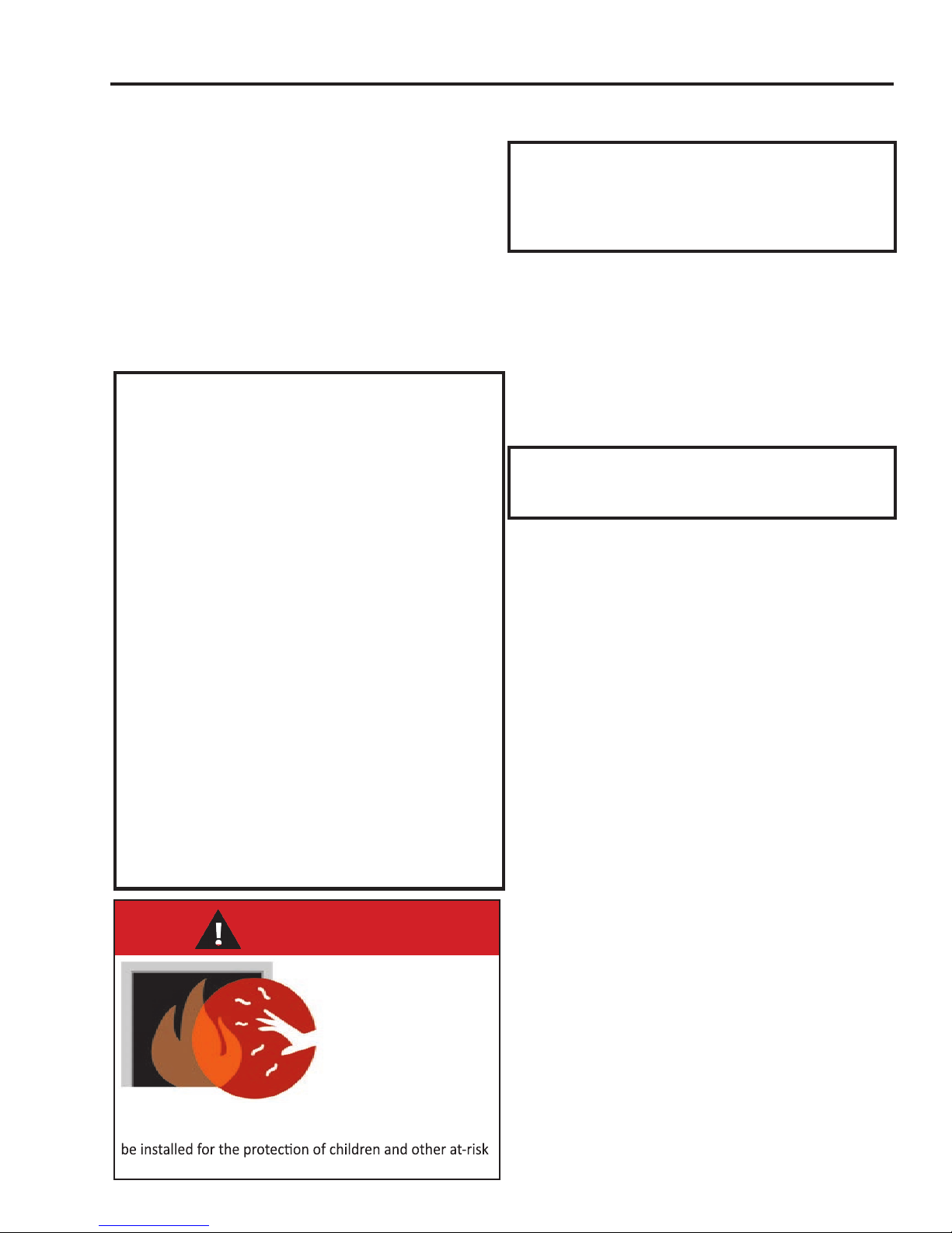
A barrier designed to reduce the risk of burns from the
hot viewing glass is provided with this appliance and shall
individuals.
FOR SAFE INSTALLATION AND OPERATION OF YOUR “ENVIRO” HEATER,
PLEASE CAREFULLY READ THE FOLLOWING INFORMATION:
• All ENVIRO gas-red appliances must be installed in
accordance with their instructions. Carefully read all the
instructions in this manual rst. Consult the building
authority having jurisdiction to determine the need for a
permit prior to commencing the installation.
• NOTE: Failure to follow these instructions could cause
a malfunction of the replace, which could result in death,
serious bodily injury, and/or property damage.
• Failure to follow these instructions may also void your
re insurance and/or warranty.
GENERAL
• Installation and repair should be done by a qualied
service person. The appliance should be inspected before
the rst use and, at least, annually by a qualied service
person. More frequent cleaning may be required due to
excessive lint from carpeting, bedding material, etc. It
is imperative the control compartments, burners and
circulating air passageways of the appliance be kept
clean.
• Due to high temperatures, the appliance should be
located out of high trafc areas and away from furniture
and draperies.
Children and adults should be alerted to the
hazards of high surface temperatures and should
stay away to avoid burn or clothing ignition.
• Young children should be carefully supervised when in
the same room as the appliance. Toddlers, young children
and others may be susceptible to accidental contact
burns. A physical barrier is required if there are at risk
individuals in the house. To restrict access to a replace
or stove install an adjustable safety gate to keep toddlers,
young children and other at risk individuals out of the
room and away from hot surfaces. Any safety screen,
guard, or barrier removed for servicing an appliance must
be replaced prior to operating the appliance.
• Clothing or other ammable materials should not be
placed on or near the appliance.
3
• A barrier designed to reduce the risk of burns from the
hot veiwing glass is provided with this appliance and shall
be installed for the protection of children and other at-risk
individuals. If the barrier becomes damaged, the barrier
shall be replaced with the manufacturer’s barrier for this
appliance
FOR YOUR SAFETY
• Installation and service must be performed by a qualied
installer, service agency or gas supplier.
• This installation must conform to local codes or, in the
absence of local codes, with the National Fuel Gas Code,
ANSI Z223.1/NFPA 54, or the Natural Gas and Propane
Installation Code, CSA B149.1.
• To prevent injury, do not allow anyone who is unfamiliar
with the stove to operate it.
• To prevent injury, if the pilot or pilot and burners
have gone out on their own, open the glass door and
wait 5 minutes to air out before attempting to relight the stove.
• Always keep the area around these appliances clear of
combustible material, gasoline and other ammable liquids
and vapours.
• These appliances should not be used as a drying rack for
clothing or for hanging Christmas stockings/decorations.
• Due to the paint curing on the stove, a faint odor and slight
smoking will likely be noticed when the stove is rst used.
Open a window until the smoking stops.
Always connect this gas stove to a vent system and vent to
the outside of the building envelope. Never vent to another
room or inside the building. Make sure the specied vent
pipe is used, properly sized and of adequate height to
provide sufcient draft. Inspect the venting system annually
for blockage and signs of deterioration.
WARNING: Failure to position the parts in accordance
with the diagrams in this booklet, or failure to use only
parts specically approved with this appliance, may result in
property damage or personal injury.
WARNING: Do not operate with the glass front removed,
cracked or broken. Replacement of the glass should be done
by a licensed or qualied service person.
• Never use solid fuels such as wood, paper, cardboard, coal,
or any ammable liquids, etc., in this appliance.
• Do not use this appliance if any part has been under water.
Immediately call a qualied service technician to inspect the
appliance and to replace any part of the control system or
any gas control which has been under water.
• Do not abuse the glass by striking it or slamming the door
shut.
• If the S40 unit is pulled out of its installation, and the vent-
air intake system is disconnected for any reason, ensure that
the vent-air intake pipes are reconnected and re-sealed in
accordance to the instructions noted in
- DIrect Vent
InItIal InstallatIon
Page 4

Table of Contents
Safety Precautions........................................................................................................2
Table of Contents.........................................................................................................4
Codes And Approvals....................................................................................................5
Specications.............................................................................................................6
Dimensions.....................................................................................................6
Rating Label Location.........................................................................................6
Operating Instructions..................................................................................................7
Lighting Instructions..........................................................................................7
Pilot Light.........................................................................................................8
Air Shutter.........................................................................................................8
Remote Controls................................................................................................8
Burner Lighting.................................................................................................9
Blower Speed .................................................................................................10
Normal Sounds During Operation......................................................................10
Maintenance And Service..............................................................................................10
Routine Maintenance.......................................................................................10
Cleaning Decorative Surfaces..........................................................................10
Cleaning the Glass...........................................................................................11
Cleaning the Firebox........................................................................................11
Replacing the Glass..........................................................................................11
Cabinet Front Removal.....................................................................................12
Glass Door Removal.........................................................................................12
Burner Removal...............................................................................................13
Fuel Conversion...............................................................................................14
Initial Installation.......................................................................................................17
Preparation for Installation...............................................................................17
Clearance to Combustibles................................................................................17
Direct Vent......................................................................................................18
Venting Clearances..........................................................................................18
Approved Venting Parts.....................................................................................19
Horizontal Termination - Minimum Vent.............................................................20
Vent Termination Restrictions............................................................................21
Allowable Vent Congurations...........................................................................22
Air Restrictor Settings......................................................................................23
Horizontal Termination.....................................................................................24
Vertical Termination ........................................................................................25
Be-Vent Drafthood Adaptor (50-3229)................................................................28
Gas Line Connection and Testing.......................................................................31
Electrical Requirements ...................................................................................32
Secondary Installation................................................................................................33
Log Set Installation..........................................................................................33
Safety Screen Replacement..............................................................................36
Trouble Shooting........................................................................................................37
Parts List....................................................................................................................38
Rating Label...............................................................................................................40
Notes.............................................................................................................................41
Warranty.................................................................................................................43
Installation Data Sheet...............................................................................................44
4
Page 5

Codes And Approvals
DIRECT VENT ONLY: This type is identied by the sufx DV. This appliance draws all of its air for
combustion from outside the dwelling, through a specially designed vent pipe system.
This appliance has been tested and approved for installations from 0 feet to 4500 feet (1372 m) above
sea level.
In the USA: The appliance may be installed at higher altitudes. Please refer to your American Gas
Association guidelines which state: the sea level rated input of Gas Designed Appliances installed at
elevations above 2000 (610 m) feet is to be reduced 4% for each 1000 feet (305 m) above sea level.
Refer also to local authorities or codes which have jurisdiction in your area regarding the de-rate
guidelines.
In Canada: When the appliance is installed at elevations above 4500 feet (1372 m), the certied high
altitude rating shall be reduced at the rate of 4% for each additional 1000 feet (305 m).
• This appliance has been tested by INTERTEK and found to comply with the established VENTED
GAS FIREPLACE HEATER standards in CANADA and the USA as follows:
VENTED GAS FIREPLACE HEATER (S40; NG/LPG)
TESTED TO: ANSI Z21.88-2014/CSA 2.33-2014 VENTED GAS FIREPLACE HEATERS
CAN/CGA 2.17-M91 (R2014) GAS FIRED APPLIANCES FOR HIGH ALTITUDES
CSA P.4.1-15 TESTING METHOD FOR MEASURING ANNUAL FIREPLACE EFFICIENCY
This ENVIRO S40 Fireplace:
• Has been certied for use with either natural or propane gases. (See rating label.)
• Is not for use with solid fuels.
• Is approved for bedroom or bed sitting room. (IN CANADA: must be installed with a listed wall
thermostat. IN USA: see current ANSI Z223.1 for installation instructions.)
• Must be installed in accordance with local codes. If none exist, use current
installation code CAN/CGA B149.1 in Canada or ANSI Z223.1/NFPA 54 in
the USA.
• Must be properly connected to an approved venting system and not connected
to a chimney ue serving a separate solid-fuel burning appliance.
IMPORTANT NOTICE (Regarding rst re up): When the unit is turned
on for the rst time, it should be turned onto high without the fan on
for the rst 4 hours. This will cure the paint, logs, gasket material and
other products used in the manufacturing process. It is advisable to open a
window or door, as the unit will start to smoke and can irritate some people.
After the unit has gone through the rst burn, turn the unit off including
the pilot, let the unit get cold then remove the glass door and clean it with
a good gas replace glass cleaner, available at your local ENVIRO dealer.
5
Page 6

Dimensions:
28 5/8"
[72.7 cm]
30 5/16"
[77 cm]
26 1/8" [66.4 cm]
4 5/8"
[11.7 cm]
22 7/16"
[57 cm]
Specifications
Rating LabeL & Lighting instRuctions Location:
The rating label and lighting instructions are located on a plate hanging on the back of of the unit.
Figure 1. S40 Dimensions
6
Page 7

Operating Instructions
For Your Safety, Read Safety Precautions And
Lighting Instructions Before Operating
WARNING: IF YOU DO NOT FOLLOW THESE INSTRUCTIONS EXACTLY A FIRE OR EXPLOSION MAY
RESULT, CAUSING PROPERTY DAMAGE, PERSONAL INJURY OF LOSS OF LIFE.
Lighting anD tuRning off instRuctions:
FOR YOUR SAFETY READ BEFORE LIGHTING
WARNING:If you do not follow these instructions exactly, a fire or explosion may result causing property damage, personal injury or loss of life
A. This appliance has a pilot which must be lighted by hand. When
lighting the pilot, follow these instructions exactly.
B. BEFORE LIGHTING smell all around the appliance area for gas.
Be sure to smell next to the floor because some gas is heavier
than air and will settle on the floor.
WHAT TO DO IF YOU SMELL GAS:
Do not try to light any appliance. Do not touch any electrical switch; do
not use any phone in your building. Immediately call your gas supplier
from a neighbor's phone. Follow the gas supplier’s instructions. If you
cannot reach your gas supplier, call the fire department.
LIGHTING INSTRUCTIONS
1. STOP! Read the safety information above on this label.
2. Set the thermostat to the lowest setting.
3. Turn off all electric power to this appliance.
4. Open the front control panel.
5. Turn off the gas control knob clockwise to the “OFF” position.
6. Open door. Wait fIve (5) minutes to clear out any gas. Close door.
Then smell for gas, including near the floor. If you smell gas, STOP!
Follow “B” in the saftey information above on this label. If you don’t
smell gas, go to the next step.
7. Find pilot-located near the center rear of the firebox. Turn the gas
control knob counter-clockwise to “PILOT”. Push the gas
control in fully and hold, keep knob depressed for about 30 seconds
after the pilot is lit. Release knob. If pilot goes out, repeat steps 4
through 5.
C. Use only your hand to push in or turn the gas control knob.
Never use tools. If the knob will not push in or turn by hand,
don’t try to repair it. Call a qualified service technician. Force or
attempted repair may result in a fire or explosion.
D. Do not use this appliance if any part has been under water.
Immediately call a qualified service technician to inspect the
appliance and to replace any part of the control system and any
gas control which has been under water.
WARNING: This gas valve has a lockout device, which will not allow the
pilot burner to be relit until the thermocouple has cooled.
-If the knob does not pop up when released, stop and immediately call your
service technician or gas supplier.
-If the pilot will not stay lit after several tries, turn the gas control knob
clockwise
8. Turn the gas control knob counter clockwise to the “ON” position.
Flip the burner switch to “ON” then turn the “HI/LOW” knob to the
desired setting.
9. Close the front control panel.
10. Turn on all electric power to the appliance.
11. Set thermostat to desired setting.
to “OFF” and call your service technician or gas supplier.
1. Set the thermostat to the lowest setting.
2. Turn off all electric power to the appliance if service is to be performed.
3. Open the front control panel and flip burner switch to “OFF”
7
TO TURN OFF GAS TO APPLIANCE
4. Turn the gas control knob clockwise to the “OFF” position.
5. Close the front control panel.
C-12454
Figure 2. Lighting Instruction Label
Page 8
Operating Instructions
PiLot Light:
1. Turn off the gas to the replace. If not recently done, remove the
glass and let the unit air out for at least ve (5) minutes to
clear out any gas. Turn on gas to the heater.
Thermopile
2. Start the pilot by pressing the gas control knob (Figure 5) and turning it
to PILOT. While pushing the gas control knob in, press the piezo ignitor
several times until the pilot light starts. Hold the gas control knob in for
30 seconds. Check that the pilot has fully engulfed the thermocouple
assembly (see Figure 3).
Figure 3. Pilot Flame
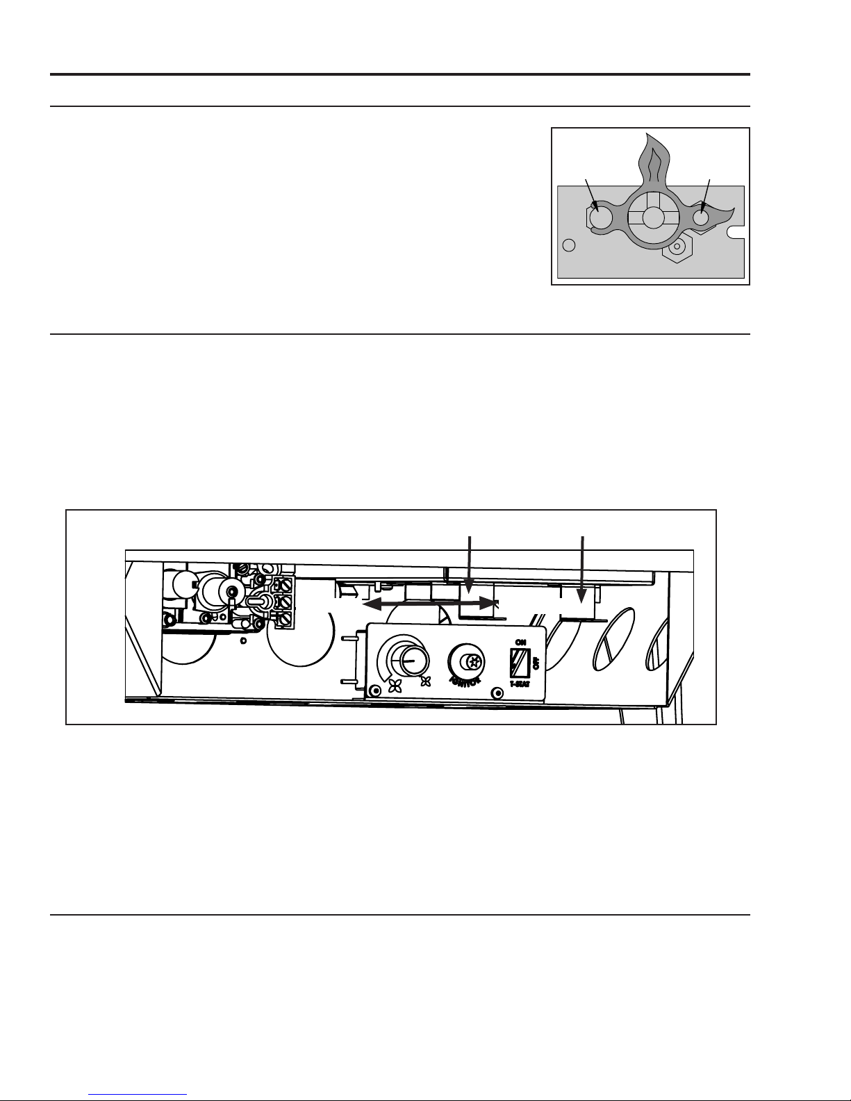
aiR shutteRs:
Behind the valve access door is the air shutter adjustment levers on the right hand side of the venturi box
(see Figure 4) above the control panel. The air shutters allow the amount of air coming into the replace
to be adjusted in order to accommodate different climates and venting arrangements. The left shutter
adjusts the rear burner and the right shutter adjusts the front burner. Start the pilot and then the burner.
Make sure the pilot ame is burning normally and none of the burner ports are plugged. Let the replace
burn for roughly fteen minutes and then examine the ames, compare the ames to Figure 44, page 35.
Thermocouple
The ideal ame will be blue at the base and light orange above. The ames should be of medium height.
If the ames look like this, no venturi adjustment is needed. If the ames are fairly short and mostly blue,
Rear Burner
Less Air
Figure 4. Air shutter adjustment lever.
More Air
Front Burner
the replace is getting too much air. Therefore, the air shutter should be closed (pushed in) slightly until
the correct ames are achieved. Flames that are very orange, with tall, dark, stringy tips, are not getting
enough air. Open (pull out) the venturi until the ames clean up. If the shut is opened, or closed all the
way, and the correct ames cannot be attained, turn off the gas and contact the dealer.
Warning: Incorrect shutter adjustment may lead to improper combustion, which is a safety hazard.
Contact the dealer if there is any concern about the venturi adjustment.
Remote contRoLs:
This replace can use an optional remote control or wall thermostat. If either of these are to be used
to control the replace for the majority of the time, leave the burner switch (Figure 7) in the remote/
thermostat position. Consult the instructions included with the remote/wall thermostat for operation
guidelines.
8
Page 9

Operating Instructions
O
L
I
T
P
TP TH TP TH
IN OUT
H
I
L
O
N
O
F
O
F
L
I
P
T
O
Hi/Low
Knob
Gas Control
Knob
For Your Safety, Read Safety Precautions And
Lighting Instructions Before Operating
buRneR Lighting:
The S40 gas valve and control panel (Figures 5 & 6) are located behind the valve access door at the front
of the stove (Figure 4). To light the burner correctly follow the steps below:
Piezo Ignitor
Fan Control
Figure 5. Gas Valve Controls
Figure 6. Control Panel
A) Make sure the pilot is lit (see PIlot lIght section) .
B) Turn gas control knob COUNTER CLOCKWISE to ON.
Burner Switch
C) Flip the burner switch, located at the top right rear of
the S40, to ON (see Figure 7)
D) Turn the HI/LO knob to the desired ame height.
NOTE: Check that all burner holes are lit.
TO TURN GAS FIREPLACE OFF:
Flip switch to OFF to turn off burners only.
If the replace is to be turned off for the season, or for
servicing, turn the gas shut off valve to OFF located at the
bottom right on the backside of the S40. DO NOT FORCE
IT. If the unit is going to be serviced, turn off the electrical
power to the unit as well.
NOTE: When the unit is turned on for the rst time, it
should be turned onto high, with the fan OFF, for the rst
two to four hours. This will cure the paint, logs, gasket
material, and other products used in the manufacturing
process. It is advised that a door or window be opened
as the unit will start to smoke, which can irritate some
people. After the unit has gone through the rst burn,
turn the unit OFF, including the pilot, and let the unit get completely cold. Then remove the glass and
clean it with a good gas replace glass cleaner, available at your local Enviro dealer. See “MaIntenance
Figure 7. Burner Switch
anD serVIce; glass Door reMoVal” and “MaIntenance anD serVIce; cleanIng the glass.”
9
Page 10
Operating Instructions
bLoweR sPeeD:
The blower will come on only when the replace is up to temperature (approximately 15 minutes). The
speed of the fan can be changed by turning the fan control knob. The blower will continue to operate
automatically after the unit has been shut off (approximately 25 minutes).To turn the blower off, turn
the knob COUNTER CLOCKWISE until it “clicks” off (Figure 6).
It is advisable not to operate the blower below
and running the blower at lower speeds could also cause premature fan failure.
1
/3 speed as it puts a strain on the windings of the blower
noRmaL sounDs DuRing oPeRation:
Table 1: Normal Sounds
Component Sound & Reason
S40 Creaking when heating up or cooling down.
Burner Light pop or poof when turned off; this is more common with LP units.
Temperature Sensor Clinking when it senses to turn the blower on or off.
Pilot Flame Quiet whisper while the pilot ame in on.
Blower / Fan Air movement that increase and decreases with the speed of the blower. The
blower is pushing the heat from the replace into the room.
Gas Control Valve Dull click when turning on or off, this is the valve opening and closing.
Maintenance And Service
Routine maintenance:
At least once a year, run through the following procedures to ensure the system is clean and working
properly. Check the burner to see if all the ports are clear and clean. Check the pilot to make sure it is not
blocked by anything. The pilot ame should be blue with little or no yellow on the tips.
Warning: Clearances must be sufcient to allow access for maintenance and service
Warning: Failure to position the parts in accordance with this manual, or failure to use only parts
specically approved with this appliance may result in property damage or personal injury.
The venting system must be periodically examined; it is recommended the examination is done by a
qualied agency.
cLeaning DecoRative suRfaces:
Painted, powder coated, or porcelain enameled surfaces should be wiped with a damp cloth periodically.
Never clean the face when it is hot. Do not use other cleaners as they may leave a residue, which can
become permanently etched into the surface.
10
Page 11

Maintenance And Service
cLeaning the gLass:
When the replace has cooled, remove the face of the replace along with the glass. See MaIntenance
anD serVIce - glass Door reMoVal. Check the gasket material on the back of the glass, making sure that
it is attached and intact.
During a cold start up, condensation will sometimes form on the glass. This is a normal condition with all
replaces. However, this condensation can allow dust and lint to cling to the glass surface. Initial paint
curing of the appliance can leave a slight lm behind the glass, a temporary problem. The glass will need
cleaning about two weeks after installation. Use a mild glass cleaner and a soft cloth. Abrasive
cleaners will damage the glass and painted surfaces. Depending on the amount of use, the glass
should require cleaning no more than two or three times a season. Do not clean the glass when it is
hot.
cLeaning the fiRebox:
Remove the logs carefully, as they are very fragile. Carefully clean any dust off the logs and remove
any lint from the burner and pilot. At this time, inspect the ceramic burner for cracking. If a problem is
suspected, contact the dealer. Check the logs for deterioration or large amounts of soot; a small amount
on the bottom side of the logs is normal. Replace the logs as shown in the seconDary InstallatIon - log
set InstallatIon section. If any logs are damaged, contact your nearest ENVIRO dealer.
RePLacing the gLass:
The glass in the replace is a high temperature ceramic. If the glass is damaged in any way, a factory
replacement is required (see Parts lIst). Wear gloves when handling damaged glass door assembly
to prevent personal injury. Do not operate with the glass front removed, cracked or broken. Removal
and replacement of the glass from the door must be done by a licensed or qualied service person.
The glass must be purchased from an ENVIRO dealer. No substitute materials are allowed.
Remove the door (see page 12). The replacement glass will come with a new gasket installed. Remove
any silicone remnants from the door. Apply high temperature silicone to the two vertical faces of the
door and install the new piece of glass with gasket (be sure to maintain edge clearances). Apply even
pressure to the glass to allow the silicone to adhere to the gasket material.
11
Page 12
Maintenance And Service
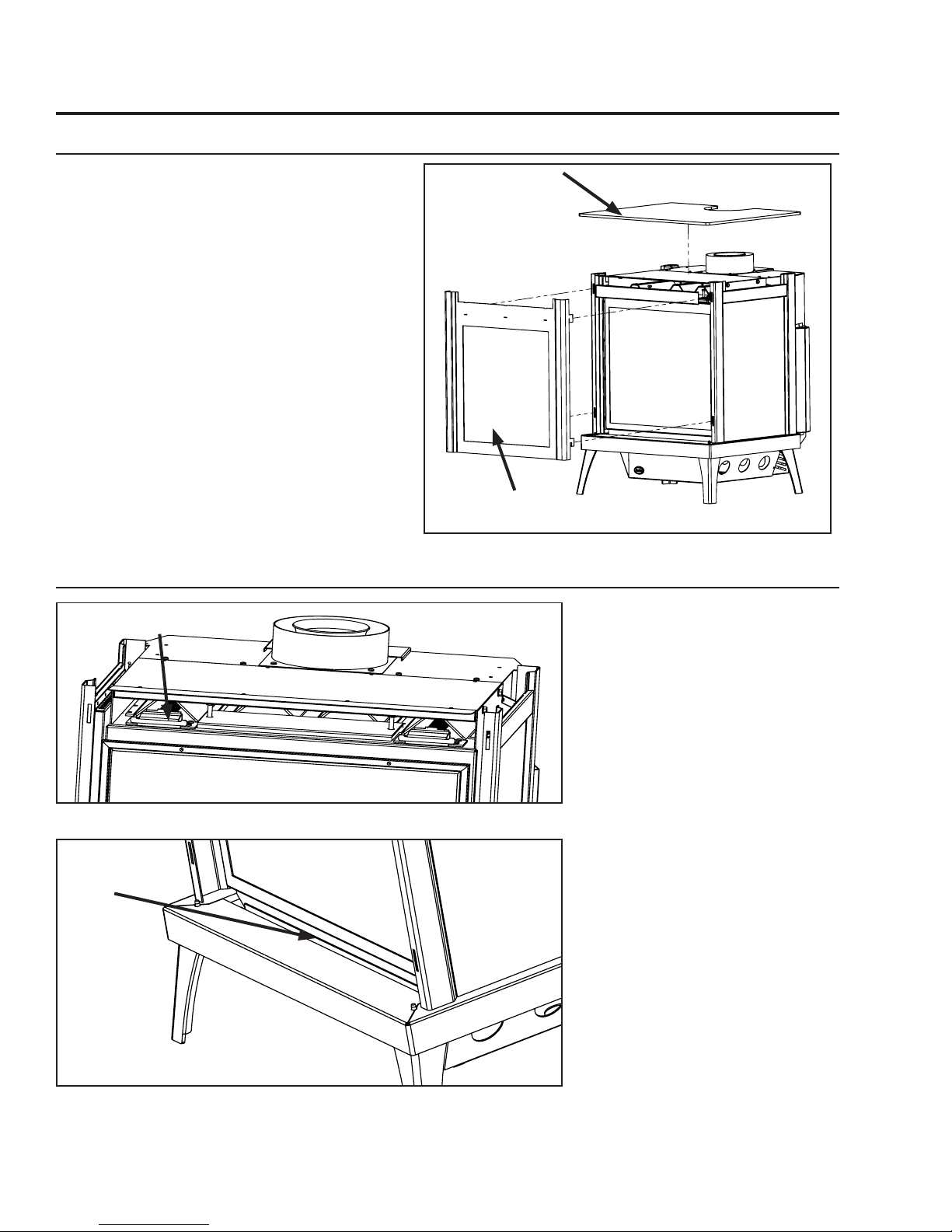
cabinet fRont RemovaL:
The cabinet front on the S40 needs to be
removed whenever access to the rebox is
required. First the S40 must be turned off
and allowed to fully cool. Next, remove the
Top Plate as shown in Figure 8 by lifting up
and out. Lay the top plate down on a towel
or blanket to prevent scratching of the nish.
The cabinet front, with safety screen attached,
can now be removed be lifting it up and out.
Lay the door face down on a towel or blanket
to prevent scratching of the nish. To re-install
the cabinet front simply reverse the procedure.
Top Plate
Cabinet
Front
gLass DooR RemovaL:
Door Latch Mechanisms
Figure 9. Top latches for glass door (cabinet front and top removed)
Alignment Slot
Figure 8. Cabinet Front Removal
In order to install the log set, and
for regular cleaning, the glass door
must be removed. The cabinet
front must rst be removed, as
outlined in the section above,
before accessing the door latches.
There are two (2) door latch
mechanisms on top the glass door
as shown in Figure 9. Each latch
can be pulled straight out and up
by hand. When the top latches are
unhooked, the door can be lifted
up out of the alignment slot at the
bottom of the rebox, shown in
Figure 10.
To replace the glass door, simply
reverse the above procedure.
Warning: Do not touch or attempt
to remove the glass door if the
replace is not completely cold.
*Parts removed
for clarity*
Figure 10. Bottom Alignment Slot for glass door.
WARNING: Never operate the
replace with the glass door
removed.
12
Page 13
Maintenance And Service
buRneR RemovaL:
The burner may need to be removed for a few reasons, including cleaning under the burner, converting
the unit to a different gas type, or to replace the burner altogether. Proceed only when the unit has
completely cooled down.
1. Remove the cabinet front, and glass door as outlined
in the MaIntenance anD serVIce - glass Door reMoVal.
2. Remove the log set as shown in SeconDary InstallatIon
- log set InstallaIon
3. Place your hands in the air slots in the burners, as
shown in gure 12, then pull forward and lift up to
dis-engage the venturi tubes.
4. Continue to lift up and rotate the burner approx. 45
degrees, as shown in Figure 13, and remove it from
the rebox. Take care not to damage the edges of
the ceramic burner as it is fragile.
Figure 12. Burner Removal - Correct Hand
Placement
Figure 11. Removing Burner.
Figure 13. Burner Removal - Rotate 45 degrees
To re-install the burner follow steps 1-4 in reverse. When placing the burner back in the unit make sure
it is properly seated and up against the intake plenum at the rear of the rebox. When installed correctly
the burner will have no side to side movement.
13
Page 14
Maintenance And Service
fueL conveRsion:
TO BE INSTALLED BY A QUALIFIED SERVICE AGENCY ONLY
Please read and understand these instructions before installing.
Warning: This conversion kit shall be installed by a qualied service agency in accordance
with the manufacturer’s instructions and all applicable codes and requirements of the
authority having jurisdiction. If the information in these instructions is not followed
exactly, a re, explosion or production of carbon monoxide may result causing property
damage, personal injury or loss of life. The qualied service agency is responsible for
the proper installation of this kit. The installation is not proper or complete until the
operation of the converted appliance is checked as specied in the manufacturer’s
instructions supplied with the kit.
Kit Parts List for all S40 models:
2 - Orice (NG: #45 & #44) or (LP: 2 x #55 , 1 x #56)
1 - Installation instruction sheet
1 - Conversion label
Carefully inspect all parts supplied with this conversion kit. If any parts have been damaged or are
missing, contact your dealer, distributor or courier company to have them replaced before starting this
installation.
Conversion Kit Installation:
1. Turn control knob on the gas valve to the “OFF” position and shut the gas supply off at the shut-off
valve upstream of the unit. CAUTION: The gas supply must be shut off prior to disconnecting the
electrical power and before proceeding with the conversion. Allow the valve and unit to cool down
to room temperature.
2. Remove the glass door as shown in the MaIntenance anD serVIce - glass Door reMoVal.
3. Carefully remove the log set.
4. Remove the burner as shown in the MaIntenance anD serVIce - Burner reMoVal.
5. Convert the burner orices:
a) Remove the main burner orices with a 3/8” socket.
b) Put a bead of pipe-thread sealant or approved Teon tape on the orice threads before installing
into the brass elbow.
c) Install the new orices from the kit
6. Convert the pilot injector:
a) Using a 7/16” wrench, turn the pilot head a ¼ turn counter-clockwise.
b) Push the slider, with your nger or at head screwdriver.
-Natural gas is marked NAT.
-Propane gas is marked LP with an indicating hole between L and P.
c) Turn the pilot head a ¼ turn clockwise; back to its original position.
14
Page 15

Maintenance And Service
Loosen
Tighten
Red o-ring
is not visible
Red o-ring
is visible
LPG Configuration
7. Convert the SIT gas valve:
a) Remove the black protection cap from the HI/LO knob by hand shown in Figure 14.
b) Insert a
it counter-clockwise until it is free and extract it.
c) Check that the screw is clean and if necessary remove dirt.
d) Flip the screw (refer to Figure 16).
e) Using the Allen wrench as shown in Figure 15, rotate the screw clockwise until a torque of 9 inch lbs.
WARNING! Do not over tighten the screw. It is recommended that you grip the wrench by the short
side.
f) Verify that if the conversion is from NG to LPG, the screw must be re-assembled with the red o-ring
visible (refer to Figure 17). If the conversion is from LPG to NG, the red o-ring of the screw must be
not visible.
g) Re-attach the black protection cap that was removed in step a (Figure 14).
5
/32” or 4 mm Allen wrench into the hexagonal key-way of the screw (see Figure 15), rotate
Figure 14: Removing
valve cap.
15
Figure 15: Removing valve
screw.
Figure 17: O-ring on valve screw.
Figure 16: Flip valve
screw.
Page 16

Maintenance And Service
8. Reinstall the burner, re grate, log set, and glass door. Also refer to seconDary InstallatIon - log set
InstallatIon in your Owner’s Manual. When re-installing the burner, ensure that the burner to pilot
hood and shield relationship is similar to what is shown in Figure 18.
9. Reconnect the main gas line if it was disconnected and open the shut-off valve at the gas line to the
unit.
10. Use a small brush to apply a warm soapy water solution to all gas connections (use a half dish soap
and half warm water). If a gas leak is present, bubbling will occur. Gas leaks can be repaired by
using an approved pipe thread sealant or approved Teon tape. NEVER USE AN OPEN FLAME WHEN
TESTING FOR LEAKS.
11. Reconnect the electrical power to the unit.
12. Relight the pilot and conrm the ame
properly covers both the thermocouple
and thermopile (see Figure 3, page 8).
Should the pilot require adjustment,
turn the adjustment screw (gure 36,
page 31) clockwise to decrease or
counterclockwise to increase until the
correct ame is achieved.
13. Relight the main burner in both the
“HI” and “LO” positions to verify
proper burner ignition, operation
and proper ame appearance (gure
44, page 35). Conrm the inlet and
manifold pressures are within the
acceptable ranges as directed in
section
connectIon anD testIng. If the S40 has been installed at an altitude higher than 2000ft
(610m) it is required to de-rate the unit accordingly and use the supplied #56 orice on
the left (LP only):
In the USA: The appliance may be installed at higher altitudes. Please refer to your American Gas
Association guidelines which state: the sea level rated input of Gas Designed Appliances installed at
elevations above 2000 (610 m) feet is to be reduced 4% for each 1000 feet (305 m) above sea level.
Refer also to local authorities or codes which have jurisdiction in your area regarding the de-rate
guidelines.
In Canada: When the appliance is installed at elevations above 4500 feet (1372 m), the certied high
altitude rating shall be reduced at the rate of 4% for each additional 1000 feet (305 m).
14. MAKE SURE that the conversion label is installed on or close to the rating label to signify that the unit
has been converted to a different fuel type.
IntIal IntallatIon - gas lIne
Figure 18. Pilot assembly
beside the burner.
16
Page 17

Initial Installation
B
A
Front
Back Wall
Side Wall
C
C
Front
Adjacent Wall
Adjacent Wall
D
A
Ceiling
Side Wall
QUALIFIED INSTALLERS ONLY
intRoDuction:
This section of the owner’s manual is for the use of qualied technicians only. Fireplace placement,
hearths, and venting terminations will be covered, as well as the gas and electrical systems. There are
several installation safety guidelines that must be adhered to. Please carefully read the safety precautions
at the front of this manual.
PRePaRation foR instaLLation:
• Remove the packaging from the appliance, and check to make sure there is no damage. If damage is
found, please report it to both the carrier and your dealer as soon as possible.
• Before beginning, carefully check the glass door and the log set
• Locate a position where the ue system of the stove can be properly installed without damaging the
integrity of the building; e.g. cutting a wall or ceiling joist.
• Check stove and ue system clearance requirements.
• Locate the stove where it can be accessed by a gas supply line.
• Locate the stove in a large and open room that is centrally located in the house. This will optimize heat
circulation and comfort.
• As the S40 is equipped with a convection fan, ensure that an electrical outlet is within 6 ft (1.8 m) of
the stove.
• The ow of combustion and ventilation air must not be obstructed.
cLeaRance to combustibLes:
Warning: Clearances must be sufcient
to allow access for maintenance and
service.
A. Sidewall to unit 11.375” (28.9 cm)
B. Backwall to unit 5.0” (12.7 cm)
C. Corner to unit 7.43 (18.9 cm)
D. Ceiling to unit 28.625” (72.7 cm)
E. Floor (hard wood & linoleum) 0”
Note: When installing on a carpeted
surface a hearth pad must be used.
minimum aLcove Dimensions:
Width 48.0” (121.9 cm)
Height 57.25” (145.4 cm)
Depth (Max.) 42” (106.68 cm)
Figure 19 Clearance to Combustibles
17
Figure 20 Clearance to Combustibles
Page 18

Initial Installation
Framing
Joists/Studs
10”
10”
QUALIFIED INSTALLERS ONLY
DiRect vent:
WARNING: This appliance has been designed to draw room air for proper heat circulation
from the bottom of the unit, and out the top front. Blocking or modifying these openings in
any way can create hazardous situations.
The vent length for the S40 must be between 36” (91 cm) and 44ft (13.4 m). This model is vented with
co-axial 4” intake, 6 5/8” exhaust aluminum or stainless steel approved rigid vent leading into a vertical or
horizontal termination cap. The ue collar of this model will t inside of a standard 4” x 6 5/8” vent and
must be either correctly interlocked or fastened, with three screws directly to the vent.
Check periodically that the vents are unrestricted. Also ensure that all direct vent pipes have been properly
sealed and installed after routine inspection or cleaning. The air intake and exhaust pipes must be installed
in the correct location on top of the S40.
venting cLeaRances:
A 1” (25 mm) clearance to combustibles must be maintained around any vertical vent pipe. Around a
horizontal vent pipe, the clearance to combustibles should be 2” (51 mm) above and 1½” (38 mm) on the
sides and bottom. When combustible materials are directly above a 90° elbow, 3” (76 mm) of clearance
are necessary.
Table 2. Vent Pipe Minimum Clearances.
Hard
Pipe
Vertical Pipe to
the Side Walls
1”
(25.4 mm)
Horizontal Pipe to
the Sides & Bottom
1½”
(38.1 mm)
Above an Elbow
Above the Unit
3”
(76.2 mm)
Above an Elbow
Not Above the Unit
3”
(76.2 mm)
Above Horizontal
Vent Pipe
2”
(51 mm)
Wall Frame 8”
(203mm) or less
10”x10”
(25x25cm)
A 10” (254 mm) x 10” (254 mm) frame (see Figure 21) will assure the proper support and spacing for
the vent pipe as it passes through the wall. Installations in Canada require that a wall thimble be used for
passing through walls and ceilings. All sealing and vapour barriers must comply with local building codes.
The conguration of the venting pipes depends on the locations
of walls, ceilings, and studs. However, the pipes cannot be of
arbitrary length and arrangement. Because the length of the
vertical and horizontal sections dramatically affects the burning
efciency of the replace, certain guidelines have been set in
InItIal InstallatIon - allowaBle Vent confIguratIons. Venting
terminals can not be recessed into a wall or siding.
WARNING: This gas appliance must not be connected
to a chimney ue serving a separate solid-burning
appliances.
Figure 21. Vent Framing For Wall or Ceiling.
18
Page 19

Initial Installation
QUALIFIED INSTALLERS ONLY
aPPRoveD venting PaRts:
Table 3: Approved Vent Manufacturers
Manufacturer Trade Name Nominal Sizes
ICC EXCELDirect 4” - 6 5/8”
M&G DuraVent DirectVent Pro 4” - 6 5/8”
The S40 replace has been tested and certied for use with M&G DuraVent DirectVent Pro and ICC EXCELDirect
venting systems. Refer to the table below for part numbers of commonly used parts for both venting systems.
For more venting parts please visit the respective manufacturers’ website.
WARNING: Do not mix parts from different vent manufacturers’ systems.
EXCEPTION TO WARNING: This product has been evaluated by Intertek for using a DirectVent Pro starting
collar in conjunction with EXCELDirect venting systems. Use of this system with the DirectVent Pro starting
collar is deemed acceptable and does not affect the Intertek listing of the appliance.
Table 4: Vent part numbers (Must state if galvanized or black wanted, PART NUMBERS).
DirectVent Pro EXCELDirect Description
46DVA-06 DL6 6” Pipe Length
46DVA-09 DL9 9” Pipe Length
46DVA-12 DL1 12” Pipe Length
46DVA-18 18” Pipe Length
46DVA-24 DL2 24” Pipe Length
46DVA-36 DL3 36” Pipe Length
46DVA-48 DL4 48” Pipe Length
46DVA-60 60” Pipe Length
DLA30 16 1/2” - 29”, Adjustable
46DVA-24TA 17” - 24”, Adjustable
46DVA-E45 4DE45 45° elbow
46DVA-E90 4DE90 90° elbow
46DVA-VSS VSS Vinyl siding standoff/sheild
46DVA-WT 4WT Wall thimble
46DVA-SC SC Storm collar
46DVA-WFS 4CS Fire stop
46DVA-WS WS Wall strap/support/band
46DVA-F6 4FA Flashing, 0/12 to 7/12 roof pitch
46DVA-F7 4FB Flashing, 8/12 to 12/12 roof pitch
46DVA-FF 4F Flat ashing
46DVA-VCH SVT High wind vertical termination
46DVA-HC HT High wind horizontal termination
46DVA-KHC 4HTK Horizontal termination kit
19
Page 20

Initial Installation
QUALIFIED INSTALLERS ONLY
hoRizontaL teRmination - minimum vent Length:
Refer to the gure for below for the minimum allowable venting setup for the S40. A termination guard
(50-3266) is required when the termination is within 7’ (2.13m) of grade.
24” (61 cm)
Minimum
Length
Approved through
wall thimble
Approved horizontal termination
Termination
Guard*
(50-3266)
12” (30.5cm)
Maximum Length
51” (130 cm)
Minimum
Length
5” (12.7cm)
Minimum Clearance
Figure 22. Minimum Vent Length
Exterior Wall
*Only required when within
7’ (2.13m) of grade
20
Page 21

Initial Installation
QUALIFIED INSTALLERS ONLY
vent teRmination RestRictions:
N
O
D
E
C
B
L
F
Fixed
Closed
Openable
B
B
Openable
Fixed
Closed
H
G
G
M
B
A
J
I
Termination Cap
Figure 23. Vent Termination Restrictions, refer to Table 5.
Letter Canadian Installation
A 12 in (30 cm) Clearance above grade, verandah, porch, deck, or balcony.
B 12 in (30 cm) 9 in (23 cm) Clearance from window or door that may be opened.
C 12 in (30 cm)* Clearance from permanently closed window (to prevent
D 24 in (60 cm)* Vertical clearance to ventilated soft located above the
E 18 in (45 cm) Clearance to unventilated soft.
F 12 in (30 cm)* Clearance to outside corner.
G 12 in (30 cm)* Clearance to inside corner.
H 3 ft (91 cm) within a height of
15 ft (4.5 m) above the meter/
regulator assembly
I 3 ft (91 cm) 3 ft (91 cm)* Radial clearance around service regulator vent outlet.
J 12 in (30 cm) 9 in (23 cm) Clearance to non-mechanical air supply inlet to building, or
K 6 ft (1.83 m) 3 ft (91 cm) above if within 10
L 7 ft (2.13 m
M 18 in / 45 cm
N 12 in (30 cm)* Clearance horizontally to any surface (such as an exterior
O 12 in (30 cm) Clearance above roof line for vertical terminations.
1
In accordance with the current CSA B149, Natural Gas and Propane Installation Code.
2
In accordance with the current ANSI Z223.1 NFPA 54, National Fuel Gas Code.
* These numbers are only estimates.
t
A vent shall not terminate directly above a side walk or paved driveway that is located between two single family dwellings
and it serves both dwellings.
+
Permitted only if verandah, porch, deck, or balcony is fully open on a minimum of two sides beneath the oor.
1
)t
+
Clearances are in accordance with local installation codes and the requirements of the gas supplier.
Air Supply Inlet
Gas MeterG
Restriction Zone
(Termination not allowed)
Table 5: Vent termination clearances.
US Installation
3 ft (91 cm) within a height of
15 ft (4.5 m) above the meter/
regulator assembly*
ft (3 m) horizontally
7 ft (2.13 m)
18 in / 45 cm
2
condensation).
terminal, within a horizontal distance of 2 ft (60 cm) from
center line of terminal.
Clearance to each side of center line extended above meter/regulator assembly.
the combustion air inlet to any other appliance.
Clearance to mechanical air supply inlet.
*t
+
Clearance above paved sidewalk or paved driveway located
on public property.
Clearance under verandah, porch, deck, or balcony.
wall) for vertical terminations.
Description
K
A
21
NOTE: Venting terminals shall not be recessed into walls or siding.
Page 22

40
39
38
37
36
35
34
33
32
31
30
29
28
27
26
25
24
23
22
21
20
19
18
17
16
15
14
13
12
11
10
9
8
7
6
5
4
3
2
1
1 2 3 4 5 6 7 8 9 10 11 12 13 14
HORIZONTAL RUN
ft
VERTICAL RISE
INSTALLATION
PROHIBITED
INSTALLATION
PROHIBITED
No Restrictor
Required
Restrictor
Setting #1
Restrictor
Setting # 2
Initial Installation
QUALIFIED INSTALLERS ONLY
aLLowabLe vent configuRations:
Figures 24 show the range of possible vent congurations for vertical and horizontal terminations. Any
layout that remains within the shaded areas is acceptable. Having the fewest number of elbows is ideal,
as they tend to disrupt air movement. Using 45˚ elbows is preferable to using 90˚ elbows. Also, a
shorter vent system will perform better
than a longer one. The total length of
horizontal vent pipe can not exceed
14 feet (4.27m) with one elbow in
the horizontal plane, and the total
vent length can not exceed 44ft
(13.4m). Any combination of rise and
run can be used as long as it lays within
the shaded area (a total of two (2) 90˚
elbows or four (4) 45˚ elbows can be
used. In addition to what is shown, if a
90˚ elbow is used in the horizontal plane,
3 feet (91.4cm) must be subtracted from
the allowable horizontal run (for each 45˚
elbow, 1½ feet must be subtracted).
Note: The air restrictor (supplied with
the unit) is required for vertical venting
runs of 10ft (3.05m) or taller. See
restrIctor settIngs for more information
Figure 24:Possible Vent Congurations for
Vertical and Horizontal Terminations.
aIr
22
Page 23

Initial Installation
QUALIFIED INSTALLERS ONLY
aiR RestRictoR:
When installing the S40 with 10ft (3.05m) or more of vertical venting it may be necessary to restrict the fresh air
supply in the rebox to control the combustion and ame appearance. To install the air restrictor supplied with
the uint the cabinet front and glass door must remove as outlined on page 12 in the
section. The rebox bafe must be removed next by removing the two front screws using a T20 screwdriver
(Figure 25). Next, remove the restrictor set screws and install the restrictor at the desired setting (refer to
Figure 26) and tighten the set screws to hold it in place. Refer to Figure 24 on the previous page for the correct
restrictor setting to use in accordance with your installation. Re-install the bafe, glass door, and cabinet front
before operating the S40.
Bafe Screws
MaIntenance anD serVIce
Figure 25: Bafe Removal
#2
#1
Restrictor
Set
Screw
Air
23
Figure 26: Installation of Air Restrictor
Page 24

Initial Installation
QUALIFIED INSTALLERS ONLY
hoRizontaL teRmination:
NOTES:
1. Horizontal pipes must not be level. For every 12 inches (305 mm) of horizontal travel
(away from the stove), there should be at least ¼ inch (6.4 mm) of vertical travel. Never
allow the vent to run downward, as this could cause high temperatures or even present
the possibility of a re.
2. The exterior of the horizontal
vent termination must not be
blocked or obstructed.
3. If the vent termination is not
being attached to wood, the
four wood screws provided
should be replaced with material
appropriate fasteners.
Wall thimble
fire stop
Horizontal wall
Termination
4. For buildings with vinyl siding,
Wall Framing
a vinyl standoff should be
installed between the vent cap
Elbow
and the exterior wall. Attach
the vinyl siding standoff to
the horizontal termination.
Note that the termination
Exhaust Pipe
bolts onto the at portion of
the standoff, providing an air
space between the wall and
Combustion air
outer pipe
the vent termination. The air
gap prevents excessive heat
from possibly melting the vinyl
siding.
5. Horizontal pipes must be
supported every 3 feet (914
Figure 27. Horizontal Vent Termination
mm). Plumber’s all round strap will sufce.
6. When running horizontal pipe, clearances to combustibles must be maintained 1½ inches (38 mm)
sides, 1½ inches (38 mm) bottom, and 2 inches (51 mm) top.
Step 1.
Set the replace in the desired location. Check to determine if wall studs will be in the way when
the venting system is attached. If this is the case, the location of the replace may have to be
adjusted or the venting may have to be offset.
Step 2. Direct vent pipe sections are designed with special twist-lock connections. Dry t the desired
combination of pipe and elbows to the appliance adaptor.
Step 3. With the pipe in the correct position and attached to the replace, mark the wall for a 10 inches
(25.4 cm) x 10 inches (25.4 cm) square hole (see Figure 21). The center of the hole should
match the center line of the horizontal pipe. Cut and frame the hole in the exterior wall where
the vent will be terminated. If the wall being penetrated is made of a non-combustible material
(i.e. masonry or concrete) a 7 inches (17.8 cm) hole is acceptable.
24
Page 25

Initial Installation
QUALIFIED INSTALLERS ONLY
Step 4. With the hole now framed, the wall thimble installed, and the pipe extending into the wall,
proceed to the outside. Attach the termination to the pipe using RTV and Mil-Pac or Rutland No
78 Stove and Gasket Cement to seal joints. The vent pipe must extend into the vent cap at least
1¼ inches (3.2 cm). Secure the connection between the vent cap and the pipe by attaching the
two (2) sheet metal straps, which extend from the vent cap assembly to the outer wall of the
vent pipe. Bend any remaining portion of the strap back towards the vent cap. Security Secure
Vent uses a twist lock cap.
Step 5.
Position the horizontal vent termination in the center of the 10 inches (25.4 cm) square hole
and attach to the exterior wall with the four screws provided. The arrow on the vent termination
should be pointing up. Run a bead of non-hardening mastic around the edges of the vent
cap, to make a seal with the wall. Ensure the proper clearances to combustibles have been
maintained.
veRticaL teRmination:
Step 1. Check the instructions for required clearances (air spaces) to combustibles when passing
through ceilings, walls, roofs, enclosures, attic rafters, or other nearby combustible surfaces.
Do not pack air spaces with insulation.
Step 2. Set the gas appliance in the desired location. Drop a plumb bob down from the ceiling to
the position of the appliance ue exit, and mark the location where the vent will penetrate
the ceiling. Drill a small hole at this point. Next, drop a plumb bob from the roof to the hole
previously drilled in the ceiling, mark the spot where the vent will penetrate the roof. Determine
if ceiling joists, roof rafters, or other framing will obstruct the venting system. You may wish to
relocate the appliance, or to offset, to avoid cutting load bearing members.
Step 3.
Step 4. Assemble the desired
To install the Round Support Box/Wall Thimble in a at ceiling, cut a 10 inch (25.4 cm) square
hole in the ceiling, centered in the hole drilled in Step 2. Frame the hole as shown in Figure 21.
lengths of black pipe
Vertical
Termination
and elbows necessary to
reach from the appliance
Elbow Strap
Storm Collar
adapter up through the
Round Support Box.
Flashing
Insure that all pipe and
elbow connections are
Roofing nails
in their fully twist-locked
position.
25
Figure 28. Vertical Vent Termination
Page 26

Initial Installation
H
Dimension ‘H’ obtained
from table below
QUALIFIED INSTALLERS ONLY
STEP 5. Cut hole in the roof centered on the small hole placed in the roof from Step 2. The hole should
be of sufcient size to meet minimum requirements for Clearance to Combustibles, as specied.
Continue to assemble lengths of pipe and elbows necessary to reach from the ceiling support
box up through the roof line. Galvanized pipe and elbows may be utilized in the attic, as well
as above the roof line. The galvanized nish is desirable above the roof line, due to the higher
corrosion resistance.
STEP 6.
Once the pipe sections have been joined, and run up through the hole in the roof, slip an elbow
strap over the exposed sections, bend the support straps outwards, and push the elbow strap
down to the roof level, as shown in Figure 28. Tighten the clamp around the pipe section. Use
a level to make sure the pipe is truly vertical. With roong nails, secure the support straps to
the roof. Seal the nails holes heads with non-hardening mastic. Trim the excess length of the
support straps that extend out beyond the edge of the ashing.
STEP 7.
Slip the ashing over the pipe section protruding through the roof. Secure the base of the
ashing to the roof with roong nails. Use a non-hardening sealant between the uphill edge
of the ashing and the roof. Insure the roong material overlaps the top edge of the ashing.
Verify that you have at least the minimum clearance to combustibles at the roof line.
STEP 8.
Continue to add pipe sections until the height of the vent cap meets the minimum code
requirements. Refer to Figure 29 and Table 7. Note that for steep roof pitches, the vent height
must be increased. In high wind conditions, nearby trees, adjoining roof lines, steep pitched
roofs, and other similar factors can result in poor draft, or down drafting. In these cases,
increasing the vent height may solve the problem.
STEP 9.
Slip the storm collar over the pipe, and push it down to the top of the roof ashing as shown
in Figure 28. Use the non-hardening sealant around the joint between the pipe and the storm
collar.
STEP 10. Twist-lock the vent cap.
Table 7: Minimum ‘H’ for Figure 29.
Roof Pitch Minimum Height (H)
Figure 29: Height of Vertical Termination;
Reference Table 7.
Feet Meters
Flat to 7/12 1 0.3
Over 7/12 to 8/12 1.5 0.46
Over 8/12 to 9/12 2 0.61
Over 9/12 to 10/12 2.5 0.76
Over 10/12 to 11/12 3.25 0.99
Over 11/12 to 12/12 4 1.22
Over 12/12 to 14/12 5 1.52
Over 14/12 to 16/12 6 1.83
Over 16/12 to 18/12 7 2.13
Over 18/12 to 20/12 7.5 2.29
Over 20/12 to 21/12 8 2.44
26
Page 27

45° elbows (x2)
Wall strap
Plumber’s tape
connected to
wal strap
Initial Installation
QUALIFIED INSTALLERS ONLY
NOTES:
(1)
If an offset is necessary in the attic to avoid
obstructions, it is important to support the vent pipe
every 3 feet (914 mm), to avoid excessive stress
on the elbows, and possible separation. Wall straps
are available for this purpose (see Figure 30).
(2) When ever possible, use 45° degree elbows instead
of 90° degree elbows. The 45° degree elbow offers
less restriction to the ow of ue gases and intake
air.
(3)
For multi story installations; a ceiling restop is
required at the second oor, and any subsequent
oors (see Figure 31). The opening should be
framed to 10” (254 mm) x 10” (254 mm) inside
dimensions, in the same manner as shown in Figure
21.
(4) Any occupied areas above the rst oor, including
Figure 30: Use of Wall Straps.
closets and storage spaces, which the
vertical vent passes through, must be
enclosed. The enclosure may be framed
and sheet-rocked with standard building
materials. However consult the appliance
manufactures installation instructions
for the minimum allowable clearance
between the outside of the vent pipe, and
the combustible surfaces of the enclosure.
Do not ll any required air spaces with
insulation.
Figure 31: Multi-Story Vent Pipe Installation.
27
Page 28

Initial Installation
Optional remote
control receiver
ON / OFF / Remote
thermostat switch
Purple
Grey
Blue
Grey
Grey
Optional
Thermostat
Optional
wall switch
Valve
Drafthood adaptor
300
o
F (149oC)
manual reset
temperature
sensor
QUALIFIED INSTALLERS ONLY
b-vent DRafthooD aDaPtoR - 50-3229:
This Drafthood Adaptor is a complete assembly and is ready to t onto your S40 in a vertical vent
application only. With the Drafthood Adaptor correctly installed and wired to the gas control valve. Your
Direct Vent Fireplace can be vented like a B-Vent Fireplace.
INSTALLATION:
WARNING: This Freestanding Drafthood Adaptor must be tted by a qualied service technician.
1. Remove the Drafthood Adaptor from the packaging. Ensure the unit and wire harness are undamaged.
If there is damage contact your dealer, distributor, or courier company before starting this installation.
2. Install the adaptor so the wires exit to the rear of the replace. Slide the Drafthood Adaptor over the
outlet pipe of the replace until the bottom of the adaptor collar stops on the top of the outlet. The
Drafthood Adaptor must be safely secured to the vent anges with either self-tapping screws and/or
high temperature sealant.
WARNING: During the tting of the Drafthood Adaptor, ensure that the wires are not pinched between
the adaptor and the collar and/or ue outlet. Ensure that the opening of the Drafthood Adaptor is not
blocked or obstructed.
3. Being careful not to run any
wiring tight across metal
edges; connect them to the
valve and “ON/OFF” switch
(refer to Figure 32).
4. Install the restrictor plate at
setting number 2, see aIr
restrIctor settIngs
WIRING DIAGRAM: When
installing the Drafthood
Adaptor onto a replace tted
with an optional wall switch
or an optional thermostat,
remove one wire from the
switch to the gas valve and
connect the Drafthood Adaptor
harness as shown in Figure 32.
GENERAL VENTING
INFORMATION:
Figure 32: Wiring Diagram for Electrical Connection.
Canadian Installations
The venting system must be installed in accordance with the current CSA B149.1 installation code and/
or local codes having jurisdiction.
U.S.A. Installations
The venting system must be installed in accordance with the current National Fuel Gas Code, ANSI
Z223.1/NFPA 54, and/or local codes having jurisdiction.
28
Page 29

4" (10cm)
Vent
6" (15cm)
Optional
decorative
cover
Check vent draft
at the top row of
the opening
Initial Installation
It is strongly recommended to install an approved chimney liner in an existing brick chimney. This will
maximize the potential draft of the chimney and lessen the effects of slow chimney start-up.
VENTING OF A FIREPLACE FITTED WITH THE DRAFTHOOD ADAPTOR:
Note: Please refer to the chimney manufacturer’s installation instructions prior to commencing the
installation. This unit may be vented to an existing masonry chimney, or where no masonry chimney is
available, an approved “B-vent” chimney, or any other approved constructed chimney/vent system (see
Figure 33). In either case, the replace must be connected to the chimney/vent using a 4” (10 cm) single
wall exible venting.
When an existing masonry chimney is utilized for the venting, it is
required the drafthood be connected to an approved 4” (10 cm)
diameter exible ue liner running the full height of the chimney.
In many jurisdictions this ue liner may be mandatory. A minimum
of 6” (15 cm) must be maintained between the venting and any
combustibles when using 4” (10 cm) single wall exible venting.
Venting Restrictions: The vent lengths below are measured
from the oor to the top of the ex venting and cannot run in the
horizontal dimension.
- Minimum: 10 ft (3.05m)
- Maximum: 30 ft (9.14m)
SPILLAGE TEST:
A spillage test must be performed prior to leaving the installed
replace with the customer. Perform this test in the following
manner:
1. Close all windows and doors in the room.
2. Start all exhaust fans in the house and the furnace blower.
3. Light the replace and set to maximum ame adjustment.
4. After a minimum of 10 minutes operation, test the chimney draft
with a smoke match at the top row of the pattern to conrm that
there is adequate draft or ‘pull’ at the openings around the body
of the Drafthood Adaptor, as shown in Figure 34.
AUTOMATIC SAFETY SHUT DOWN:
If the spill switch is activated and shuts off the main burner the
following procedure should be followed.
• Is the pilot ame still on? If not, the reason for the replace
shut down is not the spill switch.
• Turn off the pilot ame and turn off all controls. Let replace to
cool down.
• Check for blockages or restrictions in the ue and venting
components.
• Restart the replace and check for vent draft as described earlier.
• Operate the replace in a normal manner.
• If the main burner shuts down again after a period of operation,
turn off the replace and contact your service technician.
Figure 33: B-Vent Setup
Figure 34: Draft test place.
29
Page 30

Initial Installation
SPILL SWITCH REPLACEMENT:
Use the following instructions to replace the
Safety Spill Switch.
1. Turn the unit off and allow it to cool.
2. Disconnect the spill switch wires from the
valve and on/off/remote rocker switch wire
(see Figure 32).
3. Remove the four mounting screws holding
the spill switch bracket and remove the
bracket (see Figure 35).
4. Remove and replace the spill switch with a
50-885 Spill Switch Assembly using a T-20
torx type driver.
5. Follow the reverse of the previous steps.
OPTIONAL FINISHING:
In installations where venting is running from the drafthood into a non-combustible chimney the following
optional nishing technique can be used.
CAUTION: Installations where the venting connects to, or passes through, combustible
walls or ceilings, the inner vent components must be ‘B-vent’. It is not allowable in these
applications to use single wall inner vent components.
For decorative purposes a 6” (15 cm) single wall black stove pipe may be installed over the 4” (10 cm)
single wall or ‘B-Vent’.
WARNING: The use of these components is for aesthetic purposes only and does not effect
the fact that the replace, when tted with the Drafthood Adaptor, is a Natural Vent
appliance and therefore draws air in through the Drafthood Adaptor intake ports. DRAFT
RELIEF OPENINGS MUST NOT BE COVERED OR BLOCKED.
Figure 35: Spill switch installation.
30
Page 31

Initial Installation
QUALIFIED INSTALLERS ONLY
gas Line connection anD testing:
WARNING: Only persons licensed to work with gas piping may make the necessary gas connections to
this appliance.
GAS LINE CONNECTION
• This stove is equipped with a certied exible pipe located on the left side of the unit terminating
in a 3/8” female NPT tting. Consult your local authorities codes or the CAN/CGA B 149 (1 or 2)
installation code in Canada, or in the USA gas installations follow either local codes or the current
edition of the National Fuel Gas Code ANSI Z223.1.
• The efciency rating of this appliance is a product thermal efciency rating determined under
continuous operating conditions and was determined independently of any installed system.
The appliance and its shutoff valves must be
disconnected from the gas supply piping system
Gas Control
Knob
Pilot Adjustment
during any pressure testing where the pressure
exceeds ½ PSIG (3.45 KPa) or damage will occur
to the valve.
The appliance must be isolated from the gas supply
piping system by closing its individual manual
N
O
T
O
L
I
P
F
O
F
shutoff valve during any pressure testing of the gas
supply piping system at test pressures equal to or
less than ½ psig (3.45 KPa).
Always check for gas leaks with a soap
and water solution after completing the
required pressure test.
Inlet Pressure
IN OUT
Tap
Figure 36: Fully Labeled Gas Valve.
Manifold
Pressure Tap
TO TEST VALVE PRESSURES
The pressure taps are located on the top right of the valve shown in Figure 36.
•Turn set screw 1 turn counter clockwise to loosen,
•Place
5
/16” (8 mm) I.D. hose over pressure tap system.
•Check pressures using a manometer.
•When nished, release pressure, remove hose & tighten set screw.
Table 8: Pressure and BTU Information.
L
O
Screw
I
H
Hi/Low
Knob
O
L
T
I
P
TP TH TP TH
Main Orice #44 Left, #45 Right #55 mm Left & Right
Manifold Pressure 3.6” W.C. (0.89 KPa) 10.0” W.C. (2.49 KPa)
Min. Manifold Pressure 1.6” W.C. (0.40 KPa) 6.4” W.C. (1.59 KPa)
Max Supply Pressure 7.0” W.C. (1.74 KPa) 11.0” W.C. (2.74 KPa)
Min. Supply Pressure 4.5” W.C. (1.12 KPa) 10.4” W.C. (2.59 KPa)
Max BTU/hr Input 40,000 BTU/hr (11.7 KW) 39,000 BTU/hr (11.4 KW)
Min. BTU/hr Input 27,000 BTU/hr (7.91 KW) 30,000 BTU/hr (8.79 KW)
NEVER USE AN OPEN FLAME FOR LEAK TESTING.
31
Natural Gas Propane
Page 32

Initial Installation
QUALIFIED INSTALLERS ONLY
eLectRicaL RequiRements:
The fan will not operate if the appliance is cold. Once the unit is lit and the fan is set to the desired level,
the fan will automatically turn on upon reaching operating temperature. The fan will automatically turn
off after the appliance has cooled down.
The replace must be electrically connected and grounded in accordance with local codes or, in the
absence of local codes, with the current CSA C22.1 Canadian Electrical Code Part 1, Safety Standards For
Electrical Installations, or The National Electrical Code ANSI / NFPA 70 in the US.
WARNING: The electrical grounding instructions must be followed. The fan kit is equipped with a threeprong (grounding) plug for your protection against shock hazard, and should be plugged directly into a
properly grounded three-prong outlet. DO NOT cut or remove the grounding prong from this plug.
CAUTION: When servicing controls, label all wires prior to disconnection. Wiring errors can cause
improper and dangerous operation. Verify proper operation after servicing.
If any of the original wire as supplied with the appliance must be replaced, it must be replaced with 18
AWG wire with a temperature rating of 105°C
Figure 37: Fan wiring diagram.
32
Page 33

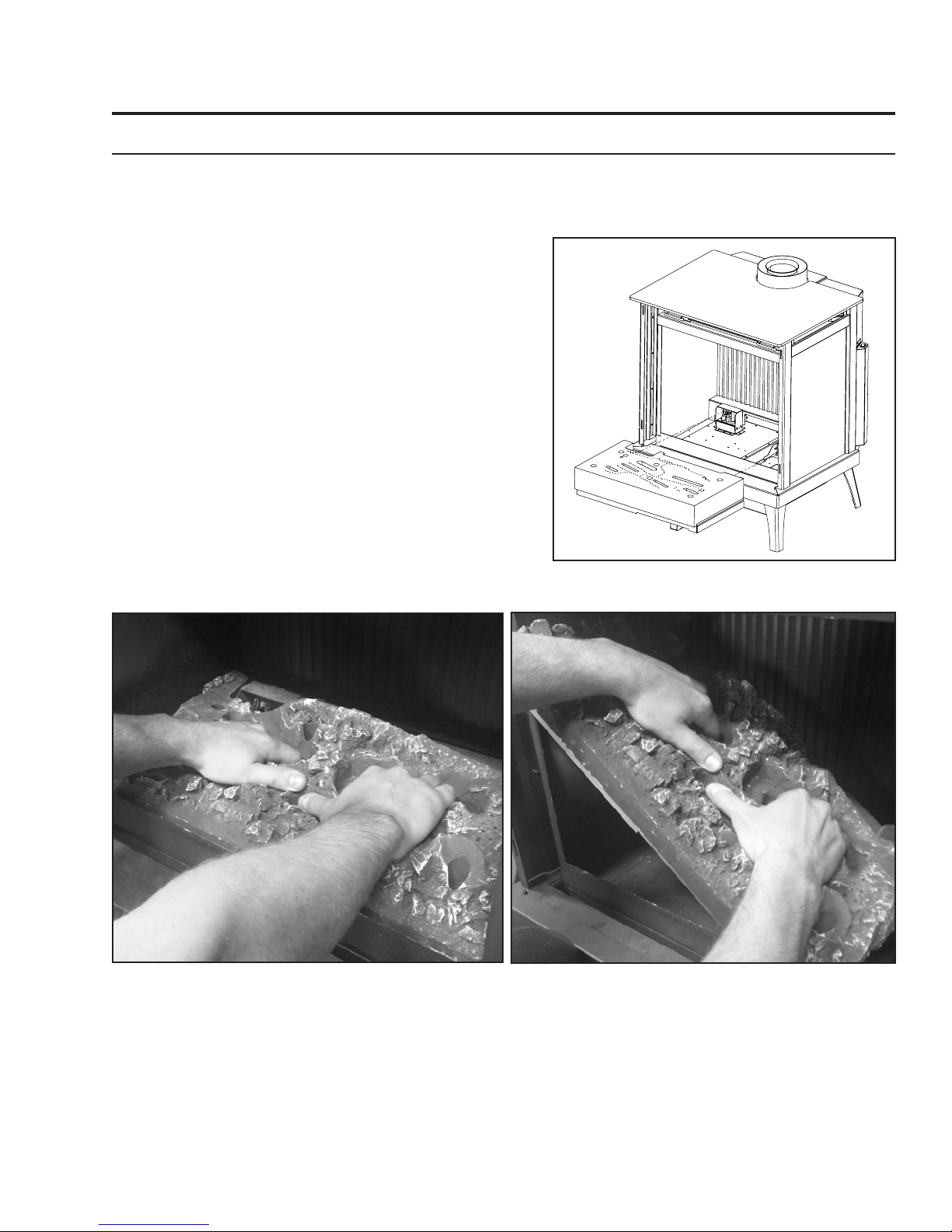
Secondary Installation
Log set instaLLation:
The placement of the logs is not arbitrary. If they are positioned incorrectly, the ames can be “pinched”
and will not burn correctly. All of the logs come with either a notch or ledge, which make alignment easier.
Using the pictures provided, carefully set the logs in place (see Figures 38 through 44).
NOTE: The logs are fragile and should be handled gently.
Please ensure that there is no damage to the
ember bed or any log prior to installation.
To Install Log Set:
1. Remove the top and front of the unit. Then
remove the glass door by releasing the top
spring latches.
2. Next, install the ember bed assembly, as
Figure 38. Ember Bed Assembly.
shown in Figure 38, by holding onto the
slots in the ember bed. The ember bed must
be held at a 45° angle, from left to right,
in order for it to t inside the rebox. When
installed correctly it should butt against the
back of the rebox.
Figure 39. Back Log.
4. Next, Install the two large at bottommed
logs in the middle of the ember bed as shown
in Figure 40.
3. Install the back log, as shown above in Figure
39, by sitting it on top of the ember bed at
the back of the rebox. There is a locating
half round on the right side, highlighted
above, to aid in correct placement
Figure 40. Rear Ember Bed Logs.
33
Page 34

Secondary Installation
Figure 41. Front Ember Bed Logs.
5. Install the front three ember bed logs as
shown in Figure 41. Note the locating notches
on the backside of the logs. The depressions
in the ember bed only allow the logs to be
installed one way.
6. Next, Install the left and right
top logs, as shown in Figure 42.
Note the locating notches on the
bottom side of both logs (areas
highlighted).
Figure 42. Top Logs.
7. Install the last log on top, on the right
side, as shown in Figure 43. Note the
locating notch on the bottom side that
matches the half round on top of the
large bottom log sitting on the ember
bed.
Figure 43. Final Top Log.
NOTE: While the glass is still removed, it is
recommended that the gas line be purged
by lighting the pilot.
34
Page 35

Secondary Installation
Figure 44. Proper Burn and Flame
8. Re-install the rebox door, then the cabinet front and top.
9. Run the unit for 15 minutes then adjust both venturis as needed. Figure 44 above depicts what
the burn and ame appearance shoud look like when the log set is properly installed and venturis
adjusted.
When re-lighting the replace for the rst time since the log set has been installed/replaced, watch
for ignition at ALL the burner ports. If a long delay is noticed, turn the appliance off and wait for it to
cool down. Then remove the glass and make sure none of the burner ports are blocked.
Maintenance: Once a year, the logs should be removed and checked for deterioration or large amounts
of soot. A small amount on the bottom side of the logs is normal. Remove and replace the logs in the
same manner described above.
If new logs are required, contact your nearest ENVIRO dealer.
Never operate the replace with the glass door removed.
35
Page 36

Secondary Installation
safety scReen RePLacement:
The S40 is supplied with a safety screen already installed on the back of the cast door. If the safety screen
becomes damaged must it be replaced with part number 50-3243 following the steps below:
Retaining
Nuts (x4)
Step 1: Turn off the S40 and allow
it to fully cool down.
Step 3: Remove the four retaining
nuts from the back of the steel
door (Figure 45) using a 11/32”
socket or wrench.
Figure 45. Safety Screen Removal
Step 2: Remove the cabinet front
as instructed in the MaIntenance
anD serVIce - caBInet front
reMoVal section.
Step 4: Remove the old safety
screen and install the new screen
by reversing the procedure. Reinstall the cabinet front and plate
top to nish.
36
Page 37

Trouble Shooting
Problem Possible Cause Solution
The main burner does not
ignite when called for.
Spark will not light the pilot
after repeatedly pressing the
spark ignitor.
Pilot will not remain lit. Problem with thermocouple
The gas valve may not be on. • Check that the gas control knob is in the “ON” position.
Thermostat is not calling for
heat.
Problem with gas valve. • Use a DC voltmeter to measure the voltage across the
Defective piezo ignitor. • Check connections to ignitor.
Broken spark electrode. • Check for broken ceramic insulation, replace electrode if
Misaligned spark electrode. • If spark is not arcing from electrode to pilot, loosen the
circuit.
• Adjust the thermostat several degrees above ambient
temperature.
TPTH and TP terminals. Main operator voltage: Open
circuit ≥ 325mV Closed circuit ≥ 100mV
• If voltage is not present, check the control circuit for
proper operation.
• If proper control system voltage is present, replace the
gas control.
• If ignitor connections are good but no spark, replace
ignitor.
broken.
screws on the pilot base adjust and tighten.
• Check for proper connection of the thermocouple to the
rear of the valve. If loose, fully tighten.
• Check pilot for full ame impingement around
thermocouple. If ame is too small, check gas pressure,
adjust pilot rate screw, check pilot head for damage.
• Check thermocouple voltage at valve. It must be greater
than 5 mV. If low, replace thermocouple.
Air in gas line (pilot dies while
knob is depressed).
Burners will not remain lit. Problem with thermopile
circuit.
Flame lifting Leak in vent pipe • Check for leaks in vent connections.
Improper vent conguration • Check vent conguration with manual.
Terminal may be recirculating
ue gases
Glass fogs up Normal Condition: after the appliance warms up the glass will clear.
**Due to additives in gas, glass may get hazy during operation** Clean as needed.
Blue Flames Normal during start up: ames will yellow as the replace heats up.
Flames are burning “dirty” or
sooting
Remote control doesn’t work Problem with the remote • One or more of the batteries are dead. See remote
Flame impingement • Check log positioning.
Problem with replace • The on/off switch is turned to OFF.
• Bleed line.
• Check gas line pressure.
• Contact dealer.
• Check gas line pressure .
• Check for ame impingement on thermopile. If low, see
“Pilot will not remain lit”.
• Check thermopile for minimum of 300 mV when burner is
switched on.
• Check wiring to thermostat for breaks.
• Check to see if terminal is on correctly.
• May need to install high wind termination cap.
• Contact dealer.
• Increase primary air by opening the venturi shutter and/
or by opening the vent restrictor.
See also “Burners will not remain lit.”
control instructions.
• The gas control valve is turned to PILOT or OFF.
• The pilot has gone out.
37
Page 38

Parts List
Reference
Number
1 Door Latch Mechanism w/ Spring (set of 2) 50-1285
2 Firebox Air Restrictor 50-3231
3 Pilot Shield 50-3232
4 120 Ceramic Fan Temperature Sensor EC-001
5 Convection Fan only 50-2493
6 FPI Fan Controller (69.5V) 115V W/FS Knob EC-039A
7 Fan Controller Knob W/Decal EC-040
8 S.I.T. Piezo Ignitor EC-023
9 FPI Burner Switch EC-026
10 Control Panel & Decal 50-2989
11 PSE Pilot Assembly - Standing Pilot 50-2513
12 S.I.T. Nova Valve - Convertible 50-1421
13 Heyco Strain Relief EC-044
14 Domestic Power Cord (115v) EC-042
15 Log Set (9 pieces) 50-3234
16 Ceramic Burner Assembly 50-3233
17 Front Door Glass w/ Gasket (16.875 x 21.0625in) 50-3235
18 Front Door Complete 50-3236
19 Ceramic Fluted Liner (1 piece) 50-3239
20 S40 Cabinet Front 50-3240
21 S40 Plate Top 50-3241
22 S40 Leg Set (4 pieces) 50-3242
23 Replacement Safety Screen 50-3243
24 B Vent Drafthood Adaptor 50-3229
25 Vent Collar Cover 50-3245
26 Termination Guard 50-3266
27 S40 Owners Manual 50-3258
- Conversion Kit - LP to NG (Nova) 50-3261
- Conversion Kit - NG to LP (Nova) 50-3262
- 12 oz. Can of Matallic Black Touch Up Paint PAINT-12-MB
Part Description Part Number
38
Page 39

17
20
23
18
12
19
3
11
1
21
24
2
25
9
5
14
13
4
6
22
10
7
8
16
27
15
26
Parts List
39
Page 40

Rating Label
Certified for use in Canada & USA /
Certifié pour installation au Canada et aux
Etats-Unis.
DO NOT REMOVE THIS LABEL / NE PAS ENLEVER CETTE ÉTIQUETTE
LISTED GAS FIREPLACE HEATER /
LISTE DES APPAREILS AU GAZ VENTILÉS
Serial No. / No. De Serié:
DATE OF MANUFACTURE /
DATE DE FABRICATION:
J F M A M J J A S O N D 2016 2017 2018 2019 2020
C-14879
MANUFACTURED BY /
FABRIQUE PAR
: SHERWOOD INDUSTRIES LTD. 6782 OLDFIELD ROAD, SAANICHTON, BC CANADA
MADE IN CANADA /
FABRIQUE AU CANADA
Model /
Modèle:
BRK
Nova Log Burner
BRKI
IPI Log Burner
4001609
Fuel /
Carburant:
NAT
(Gaz naturel)
LPG
(Propane)
INPUT (
ENTRÉE À
) at 0-4500 feet/
pied (0-1372 m):
NAT (Gaz naturel) LPG (Propane)
MAX: 40,000 Btu/hr (11.7 kWh)
MIN: 13,000 Btu/hr (3.81 kWh)
MAX: 39,000 Btu/hr (11.4 kWh)
MIN: 16,000 Btu/hr (4.69 kWh)
MANIFOLD PRESSURE
(
PRESSION DES CONDUITS
):
ORIFICE SIZE
(
GROSSEUR DE L'ORIFICE
):
Left #45 Right #44
Left #55 Right #55
GAS SUPPLY PRESSURE (PRESSION
D'APPROVISIONNEMENT DU GAZ
):
MAX: 3.6 inch W.C. (0.89 kPa)
MIN: 1.6 inch W.C. (0.39 kPa)
MAX: 10 inch W.C. (2.49 kPa)
MIN: 6.4 inch W.C. (1.59 kPa)
MAX: 7 inch W.C. (1.74 kPa)
MIN: 4.5 inch W.C. (1.12 kPa)
MAX: 11 inch W.C. (2.74 kPa)
MIN: 10.4 inch W.C. (2.59 kPa)
DV
CONFORMS TO / Conforme : ANSI Z21.88-2014, CERITIFIED TO / Agréé : CSA 2.33-2014 VENTED GAS
FIREPLACE HEATERS / APPAREIL DE CHAUFFAGE À ÉVACUATION DIRECTE, CAN/CGA 2.17-M91
(R2014) GAS FIRED APPLIANCES FOR HIGH ALTITUDES / APPAREIL AU GAZ POUR HAUTES
ALTITUDES. This appliance equipped only for altitudes 0-2000 feet (0-610 m). In Canada 0-4500 feet (1370
m) / Cet appareil peut être utilisé à des altitudes comprises entre 0 et 610 mètres (0 et 2000 pieds)
seulement. En Canada 0 et 1370 mètres (0-4500 pieds).
Vented Gas Fireplace Heater - Not for Use
with Solid Fuel / Foyer au gaz à évacuation. Ne pas utiliser avec du combustible solide
CAUTION/ATTENTION
:
Do not operate the appliance with glass removed, cracked or broken. Replacement of the panel should be done by a
S40 CLEARANCES TO COMBUSTIBLES /
CLAIRANCE DES COMBUSTIBLES:
Minimum Alcove / alcôve minimum:
From Sides / partir de côtés: 11.375” (289mm)
From Back / de l'arrière: 5” (127mm)
From Top / de haut: 28.625” (727mm)
Floor / étage: N/A
VENT PIPE CLEARANCES:
See manufacturer’s listing, label and installation instructions. May be installed in a
bedroom or bedsitting room (IN CANADA a listed wall thermostat). The total vent length must be between 36in (91.4cm)
and 44ft (13.4m). This appliance must be properly connected to a venting system in accordance with the manufacturer’s
installation instructions. If any of the venting is disassembled after installation, it must be properly resealed according to
S40
Nova Log Burner
BERKELEY CLEARANCES TO COMBUSTIBLES
/ CLAIRANCE DES COMBUSTIBLES:
Minimum Alcove / alcôve minimum:
From Sides / partir de côtés: 12” (305mm)
From Back / de l'arrière: 5” (127mm)
From Top / de haut: 27.5” (698mm)
Floor / étage: N/A
the instructions in the owners manual. This appliance must be installed in accordance with local codes, if any; if none, follow the National Fuel Gas Code, ANSI Z223.1/NFPA
54, or Natural Gas and Propane Installation Codes, CSA B149.1. This vented gas fireplace heater is not for use with air filters. FOR USE WITH GLASS DOORS CERTIFIED
WITH THE APPLIANCE ONLY. This appliance is only for use with the type of fuel indicated on this rating label. See owner's manual for details. This appliance is not
convertible for use with other gases, unless a certified kit is used. Keep burner and control compartment clean. See installation and operating instructions accompanying
appliance
.
WARNING: Failure to install this appliance per the manufacturer’s instructions or failure to use only parts specifically approved with this appliance may result in
property damage or personal injury. WARNING: Do not operate the appliance until all sections have been assembled and installed in accordance with the manufacturers
instructions. This model can be vented with approved 4” x 6 ⅝“ galvanized or stainless steel solid vent.
CLAIRANCE DES TUYAUX DE VENTILATION: Consultez les listes, les
étiquettes et les instructions d'installation du manufacturier. Ces appareils peuvent être installés dans une chambre à coucher (au CANADA avec thermostat mural). La
longueur totale du conduit doit être comprise entre 7 pouces (17.7cm) et 44 pieds (13.4m). Pour une installation dans un âtre ventilé et composé de matériaux non
combustibles. Si aucun code n'existes, utilisez les codes ci-inclus : CAN/CGA B149 au Canada ou ANSI Z223.1 / NFPA 54 aux États-Unis. Cet appareil au gaz ne doit pas
être utilisé avec des filtres à air. POUR UTILISATION UNIQUEMENT AVEC LES PORTES EN VERRE CERTIFIÉES AVEC L’APPAREIL. Les appareils de chauffage à
évacuation direct ne doivent pas être utilisés avec des carburants solides. Utilisez seulement des portes vitrées approuvées pour cet appareil. AVERTISSEMENT: Si vous
installez cet appareil selon les instructions du fabricant ou de l'échec d'utiliser seulement les pièces spécifiquement approuvé avec cet appareil peut entraîner des dommages
matériels ou corporels.Cet appareil doit être utilisé seulement avec le type de carburant mentionné et requis sur l'étiquette de classification de cet appareil. Consultez le guide
du propriétaire pour plus de détails. Cet appareil ne peut être converti pour utilisation avec d'autres gaz que celui mentionné sur l'étiquette de classification, sauf si une trousse
de conversion certifiée est utilisée. AVERTISSEMENT: Ne faites pas fonctionner l'appareil tant que toutes les pièces et les sections ne soient pas assemblées et/ou installées
en concordance avec les instructions du manufacturier. Ce modèle peut être évacué avec approuvé 4"x 6 ⅝" partie galvanisé ou en acier inoxydable solide évent.
ELECTRICAL REQUIREMENTS / BESOINS ÉLECTRIQUES:
115 V AC, 60 Hz, 0.9 Amp (fan type vented circulator, Sherwood Industries Ltd Part #50-2493 /
Ventilateur de type cage d'écureuil, Les Industries Sherwood Ltée. Pièce #50-2493.
WARNING/AVERTISSEMENT
:
Fire or explosion hazard. Can cause
property damage, severe injury, or death. This is a fast-acting thermocouple. Replace it only with another fast-acting thermocouple specified by the
manufacturer. Refer to the manual for the part number / Risque d’incendie ou d’explosion. Peut entraîner des dommages matériels, des blessures
NAT (Gaz naturel) LPG (Propane)
MAX: 40,000 Btu/hr (11.7 kWh)
MIN: 27,000 Btu/hr (7.91 kWh)
MAX: 39,000 Btu/hr (11.4 kWh)
MIN: 30,000 Btu/hr (8.79 kWh)
Left #45 Right #44
Left #55 Right #55
MAX: 3.6 inch W.C. (0.89 kPa)
MIN: 1.6 inch W.C. (0.39 kPa)
MAX: 10 inch W.C. (2.49 kPa)
MIN: 6.4 inch W.C. (1.59 kPa)
MAX: 7 inch W.C. (1.74 kPa)
MIN: 4.5 inch W.C. (1.12 kPa)
MAX: 11 inch W.C. (2.74 kPa)
MIN: 10.4 inch W.C. (2.59 kPa)
GAS TYPE (TYPE DE GAZ):
MODEL (MODÉLE):
Berkeley-IPI (BRKI) Berkeley (BRK) , S40
VITRE CHAUDE – RISQUE
DE BRÛLURES.
NE TOUCHEZ PAS UNE
VITRE NON REFROIDIE.
NE LAISSEZ JAMAIS UN
ENFANT TOUCHER LA VITRE.
HOT GLASS WILL
CAUSE BURNS
DO NOT TOUCH GLASS
UNTIL COOLED.
NEVER ALLOW CHILDREN
TO TOUCH GLASS.
licensed of qualified service person. Hot while in operation. Do not touch. Severe burns may result. Keep children, clothing, furniture, gasoline and other liquids having flammable vapours away. Keep burner and control
compartment clean. See installation and operating instructions accompanying appliance / Ne pas faire fonctionner l'appareil avec un verre enlevée, fissurée ou cassée. Remplacement du panneau doit être effectuée par
une personne de service certifié ou qualifié.Chaud pendant le fonctionnement. Ne touchez pas. Des brûlures graves peuvent en résulter. Gardez les enfants, les vêtements, meubles, essence et autres liquides ayant des
vapeurs inflammables loin. S’assurer que le brûler et le compartiment des commandes sont propres. Voir les instructions d’installation et d’utilisation qui accompagnent l’appareil.
A barrier designed to reduce the risk of
burns from the hot viewing glass is provided
with this appliance and shall be installed for
the protection of children and other at-risk
individuals
L’écran pare-étincelles fourni avec ce foyer
réduit le risque de brûlure en cas de contact
accidentel avec la vitre chaude et doit être
installé pour la protection des enfants
et des personnes à risques.
graves ou la mort. Ceci est un thermocouple rapide. Peut être remplacé uniquement par un autre thermocouple rapide spécifié par le fabricant
de l’appareil. Veuillez consulter à la notice pour le numéro de pièce
SAMPLE
40
Page 41

Notes
41
Page 42

Notes
42
Page 43

Warranty for Enviro Gas Products
Sher wood Industries Ltd. (“Sherwood”) hereby warrants, subject to the terms and
conditions herein set forth, this product against defects in material and workmanship
during the specified warranty period starting from the date of original purchase at retail.
In the event of a defect of material or workmanship during the specified warranty period,
Sherwood reserves the right to make repairs or to assess the replacement of a defective
product at Sherwood’s factory. The shipping costs are to be paid by the consumer.
All warranties by Sherwood are set for th herein and no claim shall be made against
Sherwood on any oral warranty or representation.
Conditions
A completed warranty registration must be submitted to Sherwood within 90 days
of original purchase via the online warranty registration page or via the mail-in
warranty registration card provided. Have the installer fill in the installation data
sheet in the back of the manual for warranty and future reference.
This warranty applies only to the original owner in the original location from date of
install.
The unit must have been properly installed by a qualified technician or installer, and
must meet all local and national building code requirements.
The warranty does not cover removal and re-installation costs.
Sherwood Industries Ltd. reserves the right to make changes without notice.
Sherwood Industries Ltd. and its employees or representatives will not assume
any damages, either directly or indirectly caused by improper usage, operation,
installation, servicing or maintenance of this appliance.
A proof of original purchase must be provided by you or the dealer including serial
number.
This warranty does not cover any discoloration of the safety screen mesh.
Exclusions
An expanded list of exclusions is available at www.enviro.com/help/warranty.html
This warranty does not cover:
Damage as a result of improper usage or abuse.
Damage caused from over-firing due to incorrect setup or tampering.
Damage caused by incorrect installation.
To the Dealer
Provide name, address and telephone number of purchaser and date of purchase.
Provide date of purchase. Name of installer and dealer. Serial number of the
appliance. Nature of complaint, defects or malfunction, description and part # of any
parts replaced.
Pictures or return of damaged or defective product may be required.
To the Distributor
Sign and verify that work and information are correct.
Sherwood Industries Ltd.
6782 Oldfield Road, Victoria, BC . Canada V8M 2A3
Online warranty registration: www.enviro.com/warranty/
Category One Year Two Year Limited Lifetime (7yr)
1
Parts
(unit serial number required)
Firebox Liner Panels
(excluding porcelain)
Firebox
Heat Exchanger
Burner
Ceramic Logs
Ceramic Glass
Pedestal / Legs
2
3
(excluding finish)
Door Assembly
Surround Panels
Exterior Panels
(excluding finish)
(excluding finish)
Electrical Components
Exterior Surface Finishing
Labour
1
Whereas warranty has expired, replacement parts will be warrantied for 90 days from part purchase date. Labour not included.
4
Unit serial number required.
2
Log set and panels excludes wear and tear or breakage caused by cleaning or service.
3
Glass is covered for thermal breakage. Photos of box, inside of door, and unit serial # must be supplied for breakage due to shipping.
4
Exterior Surface finishing covers plating, enamel or paint and excludes colour changes, chipping, and fingerprints.
Travel costs not included.
43
Ceramic Steel
Up to 5 years
Dec 2014
Page 44

Installation Data Sheet
The following information must be recorded by the installer for warranty purposes and future reference.
NAME OF OWNER:
_________________________________________
ADDRESS:
_________________________________________
_________________________________________
_________________________________________
PHONE:___________________________________
MODEL:___________________________________
SERIAL NUMBER:___________________________
DATE OF PURCHASE: _____________ (dd/mm/yyyy)
NAME OF DEALER:
_________________________________________
ADDRESS:
_________________________________________
_________________________________________
_________________________________________
PHONE:___________________________________
NAME OF INSTALLER:
_________________________________________
DATE OF INSTALLATION:___________(dd/mm/yyyy)
� NATURAL GAS (NAT) � PROPANE(LPG)
INLET GAS PRESSURE:_________in wc
MAIN BURNER ORIFICE:__________# DMS
PILOT ORIFICE #_________OR________in diam.
INSTALLER’S SIGNATURE:
_________________________________________
MANUFACTURED BY:
SHERWOOD INDUSTRIES LTD.
6782 OLDFIELD RD. SAANICHTON, BC, CANADA V8M 2A3
www.enviro.com
December 8, 2016
ADDRESS:
_________________________________________
_________________________________________
_________________________________________
PHONE:___________________________________
C-14868
 Loading...