

Page 1
12
Service & Warranty Dep’t
Enviritech Ltd
Kilnantogue
Rathangan
Co. Kildare
Please
affix
Postage
here
E
Ennvviirriitteecchh
U
Usseerr
M
Maannuuaall
Water
WaterWater
Water----to
toto
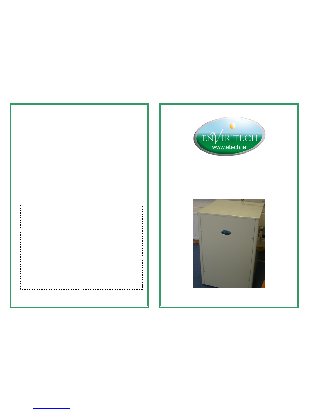
to----Water (Well) Geothermal Heat Pump
Water (Well) Geothermal Heat PumpWater (Well) Geothermal Heat Pump
Water (Well) Geothermal Heat Pump
Page 2
1. Introduction
Congratulations on selecting Enviritech’s water-to-water Heat pump, Engineered
and brought to you by Enviritech Engineering Ltd. With this heat pump, you can be
assured that you have a product, which is of the highest efficiency, reliability and
value for money.
The unit has been designed to bring the utmost of comfort to your home and to
supply you with adequate domestic hot water up to a temperature of 55 °C while
minimizing your energy cost.
Easy installation, future system extendibility, as well as user friendliness, have
been comprehensively considered during the development of this product.
Controlling the unit is also very flexible and can easily be integrated into an existing
system or form part of a complex holistic building energy management system.
We know that you will enjoy this product and will benefit from its superior quality,
efficiency and short payback period.
2. Safety Instructions
Please read the instructions in this booklet carefully because they contain
important information on how to install, use and maintain your heat pump safely as
well as containing useful tips on how to make the most of it. Keep this booklet for
future reference.
There are certain basic safety rules, which are valid for any domestic appliance.
They are as follows:
• Never touch the appliance when your hands or feet are wet or damp
• Do not use the appliance when your feet are bare
• Do not leave the appliance exposed to the natural elements (rain, sun, frost etc.
unless designed to do so).
• Do not let children (or others incapable of operating it safely) use the unit without
supervision
• Do not remove covers this may only be carried out by authorised personnel.
• Heat Pumps contain gases. If you suspect a gas leak, treat it as any other gas
leak. Ventilate the area, avoid use of naked flames & electric equipment. Call
Enviritech. All faults must be reported to Enviritech Ltd on 00 353 45 524831
(Monday to Friday 10am to 12.00 pm) before any repair work is carried out.
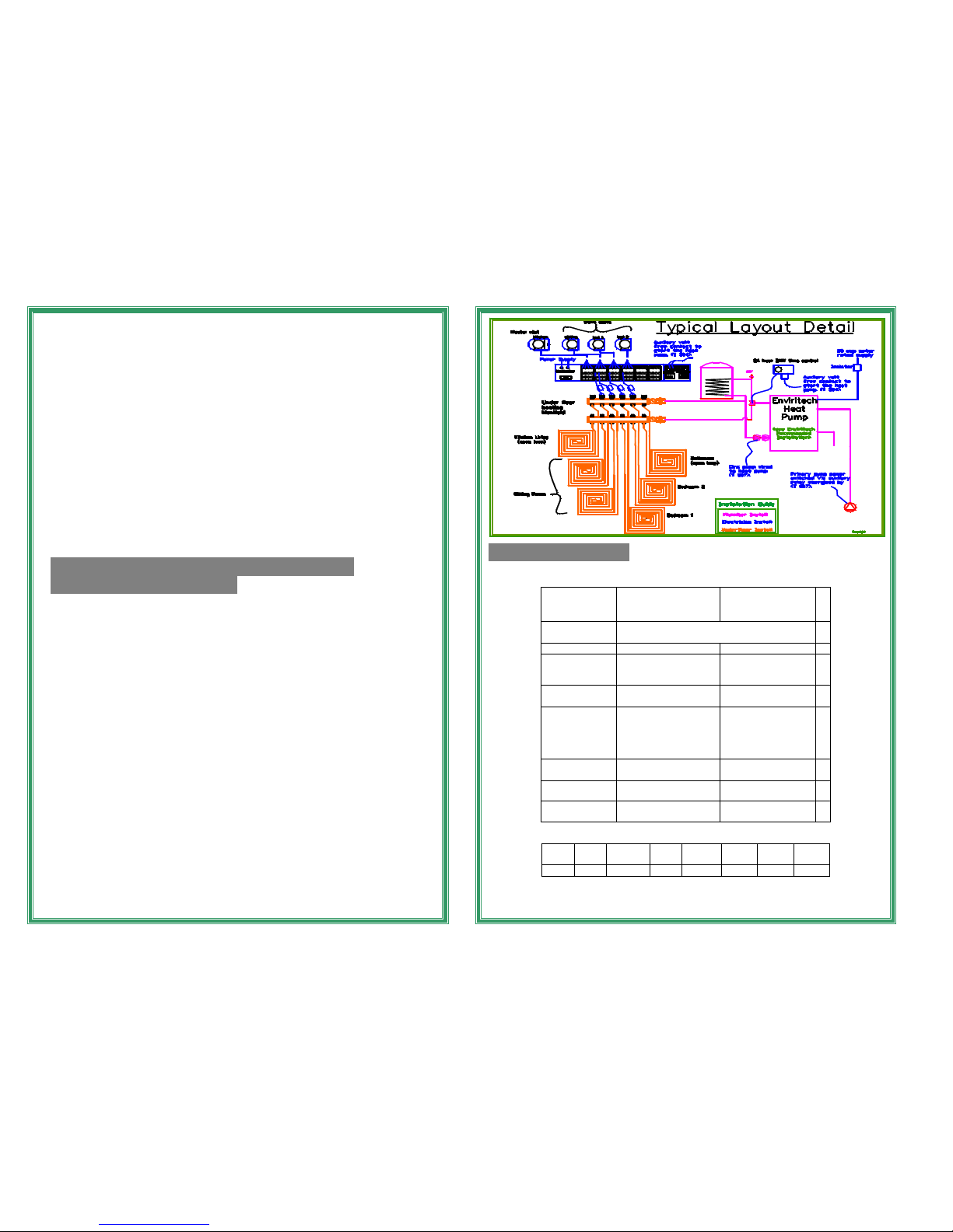
3. Installation
Connect the cold-water feed from the source water to the primary water inlet via
the Y strainer provided to the primary water inlet (1”BSP).
Connect the primary water outlet to the drain away via flow switch 1 (optional).
Connect secondary water outlet via flow switch 2 (optional) to the flow pipe of
the heating system.
Connect the heating system return pipe via Y strainer provided to the secondary
water inlet.
The electrical supply shall be provided via a 20amp motor rated MCB (3 phase
models shall be triple pole MCB).
Connect flow switch 1 between terminals 1 and 4 (loop out in absence).
Connect flow switch 2 between terminals 2 and 4 (loop out in absence). Connect
remote start signal via volt free contact between terminals 3 and 4.
Connect heating system circulating pump between the terminals 7 and 5.
Connect primary circulating pump/actuated valve between terminals 7 and 6.
PRE-START CHECKS
1. Ensure system is purged of all air.
2. Ensure all necessary valves are correct.
3. Ensure all pump directions are correct.
2
Warranty Registration Details
Please retain the following information for your records
Model No.___________ Serial No. ________________
Dealers’ Name: ___________ Purchase Date: _________
Enviritech Ltd.
Kilnantogue
Rathangan
Co. Kildare
Ph/Fax: 00 353 45 524831
Calls for faults will be accepted 10am ~ 12noon (Monday to Friday) only
Please cut along the dotted line
11
Enviritech Ltd Product Warranty Registration Form
Purchase Date: _____________________________
Model Name: ______________________________
Serial No: _________________________________
Customer Name: ____________________________
Customer Address: __________________________
__________________________________________
Contact No: ________________________________
Place of Installation: _________________________
Name of Installer: ___________________________
Contact No: ________________________________
Date of Installation: __________________________
Name of Dealer: ____________________________
Contact No: ________________________________
I agree to Enviritech’s Terms & Conditions
Signed: ____________________ Date: _______________
Page 3
4. Timer ① Range:0 - 24hours
② The timer function will be disabled if the times for automatic on
and automatic off are the same.
5. Power Down Memory
The parameter settings will not be lost on power down occasions. If the wire
controller is disconnected by accident, the system will remain working
normally. Whether the power down occurs while the unit is on or off, once the
power is restored the unit will be restored to the state prior to the occurrence
of power down (if switch JP5 is disconnected). Timer settings before the
occurrence of power down will become void after the power is restored.
6. Unit Protection
Winter Anti-freeze Protection
(1) For Secondary Water
While the unit is off once the inlet secondary water temperature is lower than the
set value for P3, in sixty seconds the unit will automatically run heating mode to
protect itself from freezing.
Anti-freeze Protection Process
Secondary water pump on ——> 4-way reversing
Valve, primary water pump on ——> compressor
On——> inlet secondary water temp > 15ºc——> All
Outputs closed in sequence——> Unit back to off or
Interlocked sate.
If the inlet secondary water temperature is no bigger than P3 plus 3ºc, the
secondary water pump will run for five minutes every thirty minutes.
(2) For Primary Water
While the unit is off, or the 2-way valve is interlocked, once the inlet primary
water temperature is lower than the set value for P3, in sixty seconds the unit will
automatically start the primary water pump. After the inlet primary water pump is
above 10ºc, the primary water pump will stop and the unit go back to off or
interlocked state.
Compressor Running Protection
1. Time delay from Compressor On to Compressor Off: sixty seconds
2. Time delay from Compressor Off to Compressor On: three minutes.
3. To ensure that the compressors will run in a balanced way, the system will
count the accumulated running time of each compressor. The system always
starts the compressor with the shortest accumulated running time first, and shuts
down the compressor with the longest accumulated running time.
4. To reduce the shock of starting current, for dual compressors system, there
will be a delay of at least 30 seconds between the start-ups of 2 compressors,
and at least 10 seconds between the shutdowns of 2 compressors.
Insufficient Secondary Water Flow Protection
All outputs will be closed if water flow is insufficient.
The system uses two approaches to check whether the secondary water flow is
insufficient.
①Water Flow Switch
The system will check Water Flow Switch (if fitted), forty seconds after the pump
is on. Insufficient secondary water flow protection will be activated if the switch is
observed to be disconnected for a continuous 10 seconds.
4
Note:
(1) Errors 01, 02, 03, 04, 05, 07, 09, 11, 13, 15, 16, 17, 18, 24, 25 can be reset
automatically after the errors have been corrected.
(2) Reset errors 06, 19, 20, 21, 22, 23 can only be reset manually.
(3) Errors 08,10,12,14 cannot be reset on the panel but will require a power
down sequence.
(4) Errors 20, 21, 22, 23 will be disabled within the first five minutes after the
compressor is started.
10. After Sales Service
Before calling for Service
1. Check the trouble-shooting guide carefully to see if you can correct the fault
yourself.
2. Power the unit off at the mains isolator, wait for ten minutes and then try to
operate the unit once more.
If both attempts fail, please call for Service, describe the fault and give the
Model Number, Service Number, your address and phone number.
Where to find Model No and Service No:
On left hand side of unit.
11. Warranty Details
The warranty applies solely to the heat pump. If any part is found to be
defective due to faulty manufacture within the guarantee period of 2 years
from date of purchase, Enviritech Engineering Ltd. through its Authorised
Service Repairers will affect the repair or replacement to the customer
providing:
(a) The fault is reported immediately & directly to Enviritech Engineering.
(b) Proof and date of purchase is provided.
(c) The fault is not caused by bad installation, misuse, neglect or faulty
adjustment by the user.
(d) The failure has not occurred through fair wear and tear.
(e) The machine has not been serviced or repaired, taken apart or tampered with
by any person unauthorised by Enviritech Engineering Ltd.
(f) The Machine has not been used for hire, commercially or in a portable
manner.
(g) The machine is owned by the original purchaser.
(h) The correct voltage is supplied.
(i) The product guarantee card has been returned.
Failures due to the following are not covered, therefore it is important that you read
the instructions contained in the Operator’s Manual and understand how to operate
and maintain your machine:
1. Incorrect parameter setting.
2. Isolation valves inadvertently turned off.
3. Poor or no circulation.
4. Insufficient and / or poor water quality supply.
5. Insufficient frost protection / Insulation.
9
WWAARRNNIINNGG
A certified Service technician only, must carry out Service. It is
dangerous for anyone else to perform any repair service.
Page 4
6. Incorrect / Inadequate control.
The warranty does not cover damage caused by outside factors, such as lightning,
water, fire, frost, nor does it apply if the unit numbers on the equipment have been
changed, removed or rendered illegible.
Other failures not covered by guarantee;
• Failures as a result of not reporting an initial fault.
• Failures as a result of sudden impact.
• Failures as a result of not using the product in accordance with the instructions
and recommendations contained in this Operator’s Manual.
• Failure as a result of the machine been stored or transported in a non-up right
position.
• Failure to service unit within one year of installation with authorized personnel.
• Failure as a result of any parts fitted to the unit, which are not the original
manufacturer’s parts.
Caution!
Enviritech Ltd. does not accept liability under the warranty for defects caused in
whole or part, directly or indirectly by the fitting of replacement parts or additional
parts that are not either manufactured or approved by Enviritech Ltd, or by the
machine having been modified in any way.
12. Who to contact in the event of a fault
during guarantee period.
Please refer to warranty card provided.
The following items listed are considered as wearing parts and their life is
dependent on regular maintenance and is therefore not normally subject to a
valid warranty claim:
1. Screws and fixings
2. Refrigerant charge
3. Fouling of filters, pipelines, valves and heat exchangers.
4. Surface protection, painting & corrosion.
5. Fuses, switches, relays, MCB’s and electrical protective devices.
This guarantee is additional to, and in no way diminishes the customer’s statutory rights.
The manufacturer declines all responsibility in the event of any printing mistakes in
this booklet. The manufacturer also reserves the right to make appropriate
modifications to its products, its warranty and its terms and conditions without
changing the essential characteristics.
10
©
4. System Settings
1. Multiple functions are available for selection by users (through switching
between disconnected and connected state.)
2. Default Values (D=disconnected, C=Connected):
JP1 JP2
JP3
JP4 JP5 JP6 JP7 JP8
D D C D D D D C
3. For valid function selection, setting should be finished before power is up.
3
Jumper
Disconnected Loop Wired
JP1
Equipments self check-up. User regulation not
allowed.
JP2 Both Systems Valid System 1 valid only
JP3
Compressor starts
one minute after
power is up
Compressor starts
three minutes after
power is up
JP4
Primary Unit Secondary Unit
JP5 Automatic Unit Start-
up allowed when
power is restored
Only manual /
remote signal unit
start-up allowed
when power is
restored
JP6
Interlock control valid
Interlock control not
valid
JP7
JP8
Cooling only Heat Pump
Page 5
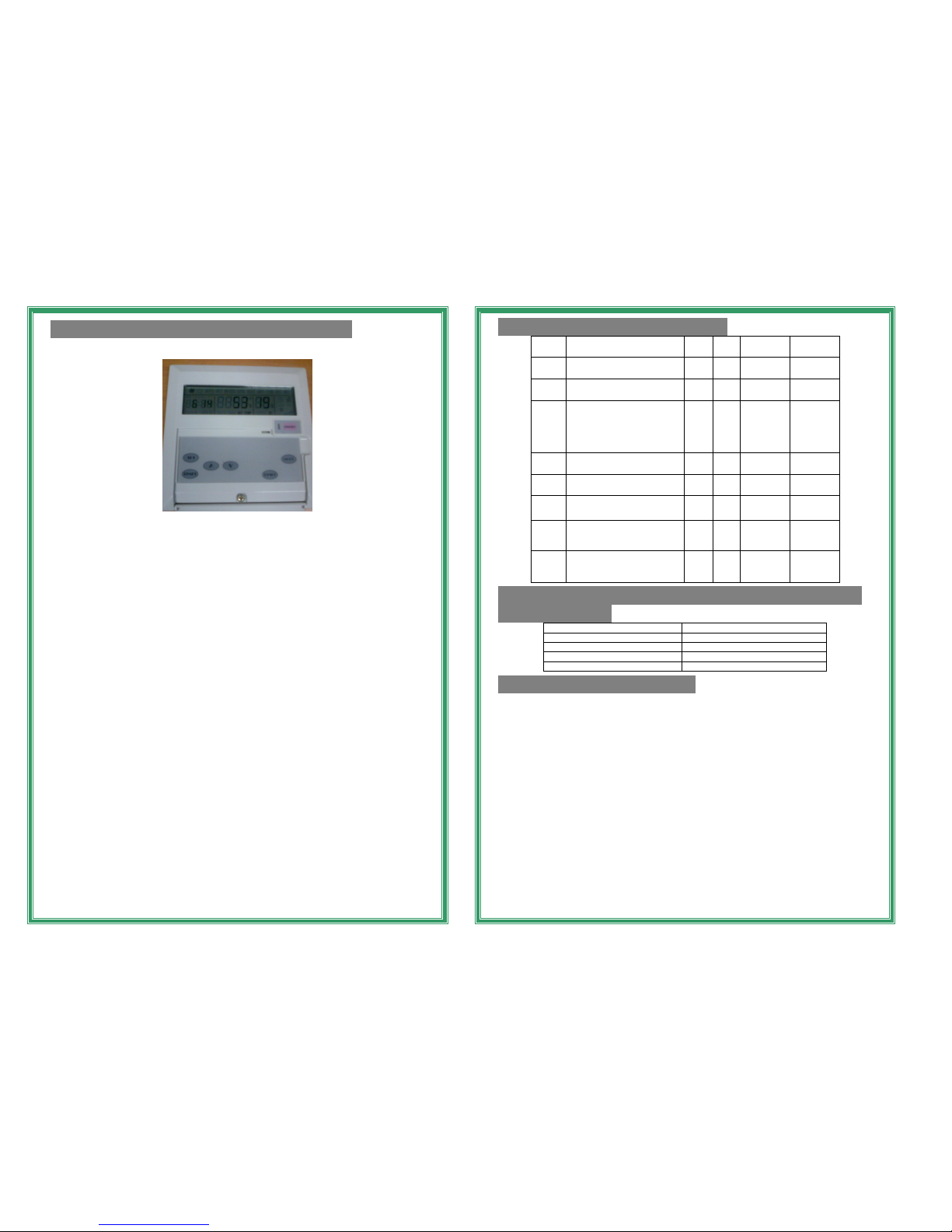
5. Panel Regulation & Parameter Setting
1. Panel Buttons
2.... Panel Regulation
(1)ON/OFF BUTTON Press this button to switch on or off the unit.
(2)MODE BUTTON
Press this button to switch the unit between HEAT and COOL mode. Only
avail on deluxe models
(3)TIMMER BUTTON
Pressing this button once, the user can set the “HOUR” digit for
“AUTOMATIC ON”.
Pressing this button once more, the user can set the “MINUTE” digit for
“AUTMATIC ON”.
Pressing this button once more, the user can set the “HOUR” digit for
“AUTOMATIC OFF”.
Pressing this button once more, the user can set the “MINUTE” digit for
“AUTOMATIC OFF”.
Pressing this button once more will restore the screen back to normal display.
Pressing this button continuously for 5 seconds, the user can adjust the clock
time.
Further adjustment through “△” “▽” buttons.
(4)RESET BUTTON
If a fault has already been remedied, pressing RESET Button will clear
up the fault code on the display screen. Otherwise, pressing RESET
Button is void.
(5) “△” “▽” BUTTONS Press these buttons to change the values of the
parameters.
(6) SET BUTTON
Press this button to check up the running parameters.
Press this button continuously for ten seconds to set parameter values.
The control panel will be restored from parameter setting mode if no
buttons are pressed within 5 seconds.
6
6. Parameter Setting & Display
Serial
No.
Parameter Name Max Min Precision Default
P0 Outlet Secondary Water
Temp Too Low in Cooling
10 0
℃ 5℃
P1 Outlet Secondary Water
Temp Too High in Heating
67 40
℃
60
P2 Temp Difference Between
Inlet and Outlet
Secondary Water Temps
for Insufficient Water Flow
Protection
30 5
℃
20
P3 Winter Anti Freeze
Protection Cut-in Temp
5 0
℃
3
P4 Inlet/Outlet Primary Water
Temp Too High in Cooling
65 40
℃
55
P5
Inlet/Outlet Primary Water
Temp Too Low in Heating
25 3
℃
10
P6
Backup Electricity Heating
Element Cut-in Air Temp
10 -5
℃
5
P7 Temp Difference Between
Inlet and Outlet Water
Temps
10 0
℃
5
7. Temperature Check-up (press the set button
to display)
Serial No. Parameter
0 Outlet Secondary Water Temp
1 Ambient Air Temp
2 Inlet Primary Water Temp
3 Outlet Primary Water Temp
8. Trouble Shooting Guide
If the Heat Pump does not operate, please check
the following:-
1. Is there power getting to unit
2. Has the MCB tripped?
3. Are all valves open?
4. Is there a fault reading on the control panel.
5. Is there sufficient circulation in the system?
6. Is there adequate water flow.
7. Check refrigerant gases on side panel, ensure both are reading above 0.4Mpa
How to maintain the Heat Pump and it’s Accessories
• Cleaning is the only maintenance operation normally required. It must be
carried out with the unit Isolated. Use a liquid detergent, water and a cloth
or sponge to clean it.
• Do not use chemical products or abrasive compounds to clean any part.
• Annual service by an authorized agent is advised In order to ensure that
your heat pump continues to operate efficiently and effectively. Enviritech
Engineering can advise you of a suitable agent in your area.
• Y strainers may require cleaning periodically depending on the water
quality. Simply open the cap and remove the strainer. Rinse until clean and
replace. 7
Page 6
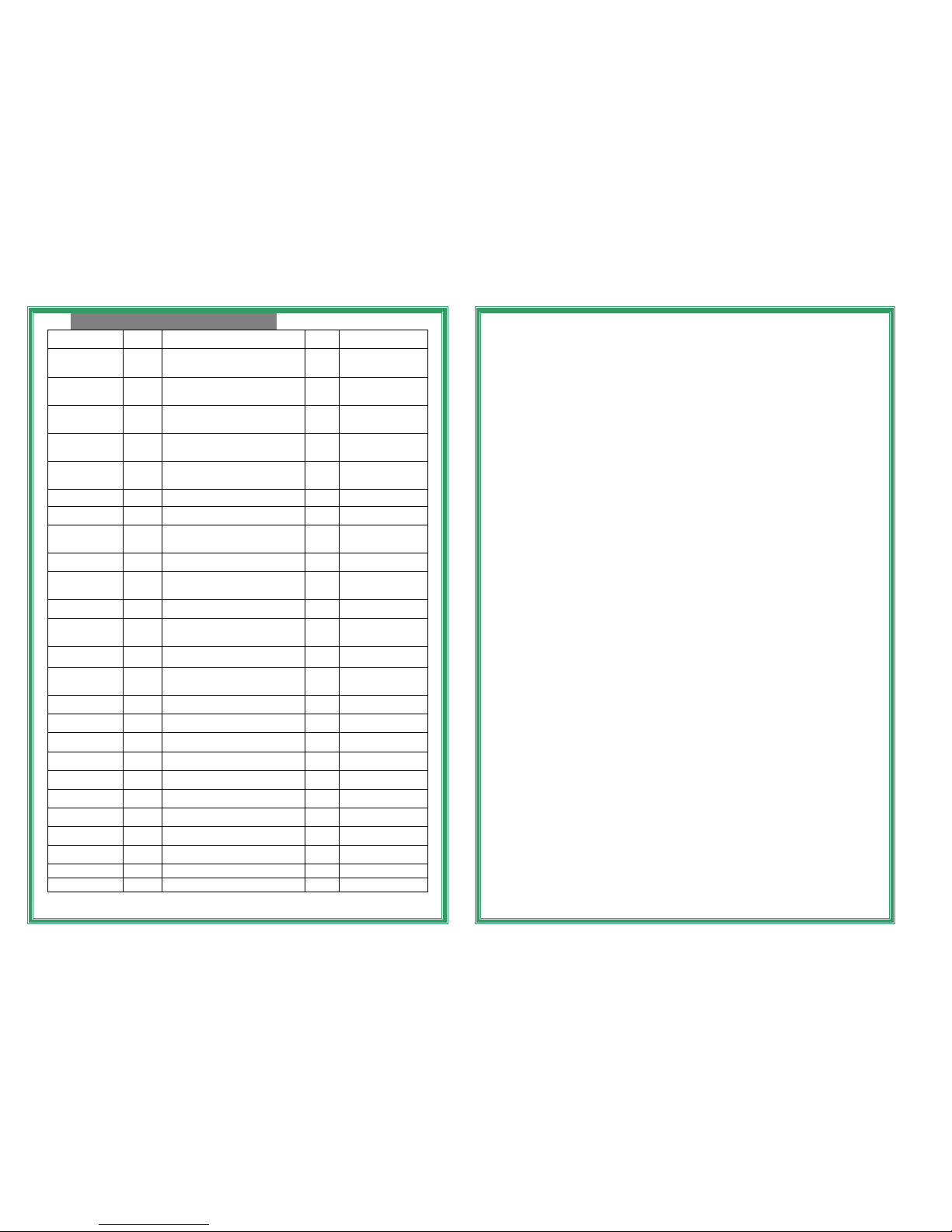
9. Unit Fault and Protection
Error No.
Input
Port
Fault Code Treatment
1 TH1
Inlet Secondary Water Temperature
Sensor Fault
01
Close All Outputs
(Except For Water
Pump)
2 TH2
Outlet Secondary Water
Temperature Sensor Fault
02
Close All Outputs
(Except For Water
Pump)
3 TH3
Ambient Air Temperature Sensor
Fault
03
Close All Outputs
(Except For Water
Pump)
4 TH4
Inlet Primary Water Temperature
Sensor Fault
04
Close All Outputs
(Except For Water
Pump)
5 TH5
Outlet Primary Water Temperature
Sensor Fault
05
Close All Outputs
(Except For Water
Pump)
6 FLOW Insufficient W ater Flow 06 Close All Outputs
7 HP1
High Pressure Protection-
Compressor 1
07 Compressor 1 Off
8 ///
More Than 2 Times High Pressure
Protection in One Hour-Compressor 1 08 Compressor 1 Off
9 LP1
Low Pressure Protection-
Compressor 1
09 Compressor 1 Off
10 ///
More Than 2 Times Low Pressure
Protection in One Hour-Compressor 1 10 Compressor 1 Off
11 HP2
High Pressure Protection-
Compressor 2
11 Compressor 2 Off
12 ///
More Than 2 Times High Pressure
Protection in One Hour-Compressor 2 12 Compressor 2 Off
13 LP2
Low Pressure Protection-
Compressor 2
13 Compressor 2 Off
14 ///
More Than 2 Times Low Pressure
Protection in One Hour-Compressor 2 14 Compressor 2 Off
15 ///
Outlet Secondary Water Temp Too
High in Heating
15 Compressor(s) Off
16 / / /
Inlet Secondary Water Temp Too
Low in Cooling
16 Compressor(s) Off
17 / / /
Winter Anti Freeze Protection for
Secondary Water
17 Starts H eating Mode
18 / / /
Winter Anti Freeze Protection for
Primary Water
18
Starts Primary Water
Pump
19 FW-C
Primary Water Flow Switch
Protection
19
Close All Outputs
(Except Water pump)
20 ///
Inlet Primary Water Temp too High in
Cooling
20 One Compressor Off
21 ///
Outlet Primary Water Temp too High
in Cooling
21 One Compressor Off
22 ///
Inlet Primary Water Temp too Low in
Heating
22 One Compressor Off
23 ///
Outlet Primary Water Temp too Low
in Heating
23 One Compressor Off
24 /// C ommunication Fault 24 Close All Outputs
25 BUS Synthetic Fault 25 Close All Outputs
8
②Temperature Difference between Inlet and Outlet Secondary Water
Temperatures
When the difference is bigger than the set value for P2, insufficient water flow
protection will be activated.
Primary Water Flow Switch Protection
The system will check the Primary Water Flow Switch (if fitted) forty seconds
after the primary water pump is on. If the switch is observed to be disconnected
for a continuous 10 seconds, Insufficient Primary Water Flow Protection will be
activated and the compressor(s) will be shut down.
High/Low Pressure Protection
1 High Pressure Protection: If the High Pressure Switch is observed to be
disconnected, High Pressure Protection will be activated and the
corresponding compressor will be shut down.
2 Low Pressure Protection: When the Low Pressure Switch is observed to be
disconnected for a continuous 30 seconds, the corresponding compressor will
be shut down. (Low Pressure switch will not be observed within 30 seconds
before the compressor is started).
The system will reset automatically (if the fault is corrected) if the number of
Protection occurrence is not more than two in one hour; otherwise, the fault will
be locked.
Outlet Secondary Water Temp Too High in Heating
In heating mode, if the outlet secondary water temperature is higher than the
set value for P1, compressor(s) will be shut down till the outlet water
temperature becomes 15℃ lower than the set value.
Inlet/Outlet Primary Water Temp Too High in Cooling
In cooling mode, five minutes after the compressor is started, if the inlet or
outlet primary water temperature is higher than the set value for P4, one
compressor is shutdown.
Inlet/Outlet Secondary Water Temp Too Low in Heating
In heating mode, five minutes after the compressor is started, if the inlet or
outlet secondary water temperature is higher than the set value for P5, one
compressor is shutdown.
Heating/Cooling Signal Output
Cooling Signal (P-C): In cooling mode, thirty seconds after the first compressor
in the Primary unit is started, the signal will be transmitted to other units. After
both compressors are shut down, the signal will be cut out.
Heating Signal (P-H): In heating mode, thirty seconds after the first compressor
in the Primary unit is started, the signal will be transmitted to other units. After
both compressors are shut down, the signal will be cut out.
Interlock Function (Remote Start signal T3&4)
When the unit is off, the system will keep checking the state of the interlock
switch. If the switch is connected, the unit will be started. If the switch
is disconnected, the unit will be shut down.
5
 Loading...