

Page 1
Zhejiang Envertech Corporation Ltd.
Tel:+86 579 8926 6326
Web:www.envertec.com
Add:24th Floor, Jintong Mansion,
Center of Headquarters, Yongkang City,
Zhejiang Province, China
MICROINVERTER
EVT300
User Manual
www.envertec.com
Page 2

Content
1. Important Safety Information..........................................................................
1.1 Read it First.............................................................................................
1.2 Safety Instructions.................................................................................................
2. Envertech Microinverter System.........................................................
2.1 How it Works...........................................................................................
2.2 Monitoring Device: EnverBridge..............................................................
2.3 Optimal Reliability....................................................................................
2.4 Simple Design........................................................................................
3. Product Information..............................................................................
3.1 Overview..................................................................................................
3.2 Major Characteristics...............................................................................
3.3 Datasheet................................................................................................
4. Packing checklist..................................................................................
4.1 Accessories.............................................................................................
4.2 Product Description.................................................................................
4.3 Further information..................................................................................
5. Planning of Microinverter Installation.................................................
5.1 Symbols on Inverter.................................................................................
5.2 Accessories..............................................................................................
5.3 Connection Method..................................................................................
6. Microinverter Installation......................................................................
7. Debugging and Operaing......................................................................
7.1 Energize the System...............................................................................
7.2 EVT300 Operation...................................................................................
8. Troubleshooting and Maintenance......................................................
8.1 LED Status Indications and Error Reporting...........................................
8.2 Troubleshoot an Inoperable Microinverter...............................................
8.3 Disconnect Microinverters from PV Modules..........................................
9. System Diagram....................................................................................
10. Recycling and disposal........................................................................
11. Contact...................................................................................................
1
1
1
2
3
3
3
4
4
4
4
5
5
5
6
6
6
6
7
7
8
13
14
14
15
15
15
16
17
18
18
Page 3
1.Important Safety Information
1.1 Read it First
This manual contains important instructions for installation and maintenance of the
EVT300 microinverter.
To reduce the risk of electrical shock, and to ensure safe installation and operation of
the microinverter, the following safety symbols appear throughout this document to
indicate dangerous conditions and important safety instructions.
Connect the Envertech microinverter to the utility grid only after you have completed all
installation procedures and receiving approval from the electric utility company.
Please be kindly noted that the Envertech microinverter itself is a heat sink. Under normal
operating conditions, its temperature is 20°C above ambient, but under extreme conditions
the microinverter can reach a temperature of 80°C.
Do not disconnect the PV module from the Envertech microinverter without firstly
disconnecting AC power.
DANGER
DANGER indicates a hazardous situation which, if not avoided,
!
will result in death or serious injury.
WARNING
!
WARNING indicates a hazardous situation which, if not avoided,
can result in death or serious injury or moderate injury.
NOTICE
NOTICE indicates a situation that can result in property damage,
!
if not avoided.
1.2 Safety Instructions
Do not use Envertech equipment in a manner not specified by the manufacturer. Doing so
may cause death or injury to persons, or damage to equipment.
Be aware that only qualified personnel should install or replace the Envertech microinverters
and the Cable and accessories.
Do not attempt to repair the Envertech microinverter; it contains no user-serviceable parts. If
it fails, contact Envertech customer service to start the replacement process. Tampering with
or opening the Envertech microinverter will void the warranty.
If the AC cable on the microinverter is damaged or broken, do not install the unit.
Before installing or using the Envertech microinverter, read all instructions and cautionary
markings in the technical description and on the Envertech microinverter system and the PV
equipment.
2. Envertech Microinverter System
The Envertech microinverter system is an on-grid microinverter system with world
top-class technology. This manual gave details about safe installation and operation
of the Envertech Microinverter.
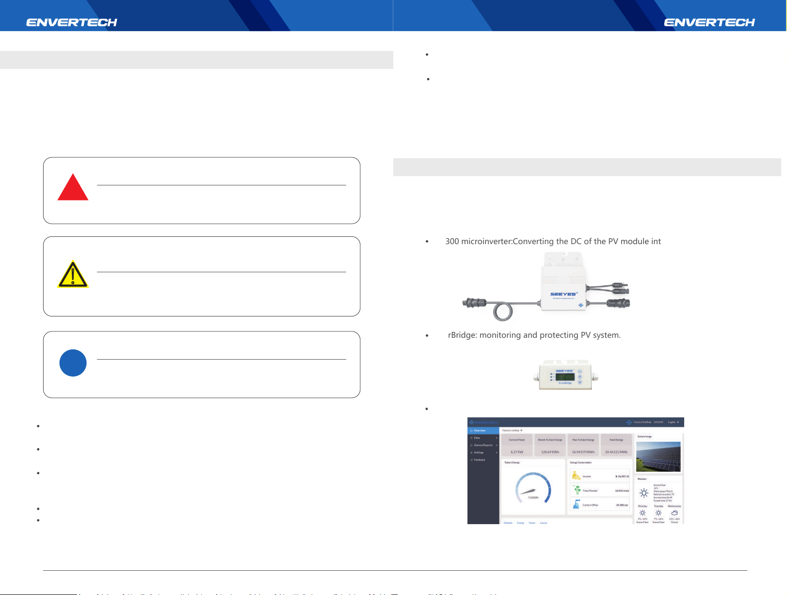
The three key elements of an Envertech microinverter system include :
EVT300 microinverter:Converting the DC of the PV module into AC
EnverBridge: monitoring and protecting PV system.
EnverPortal: http://www.envertecportal.com
1 2
Page 4
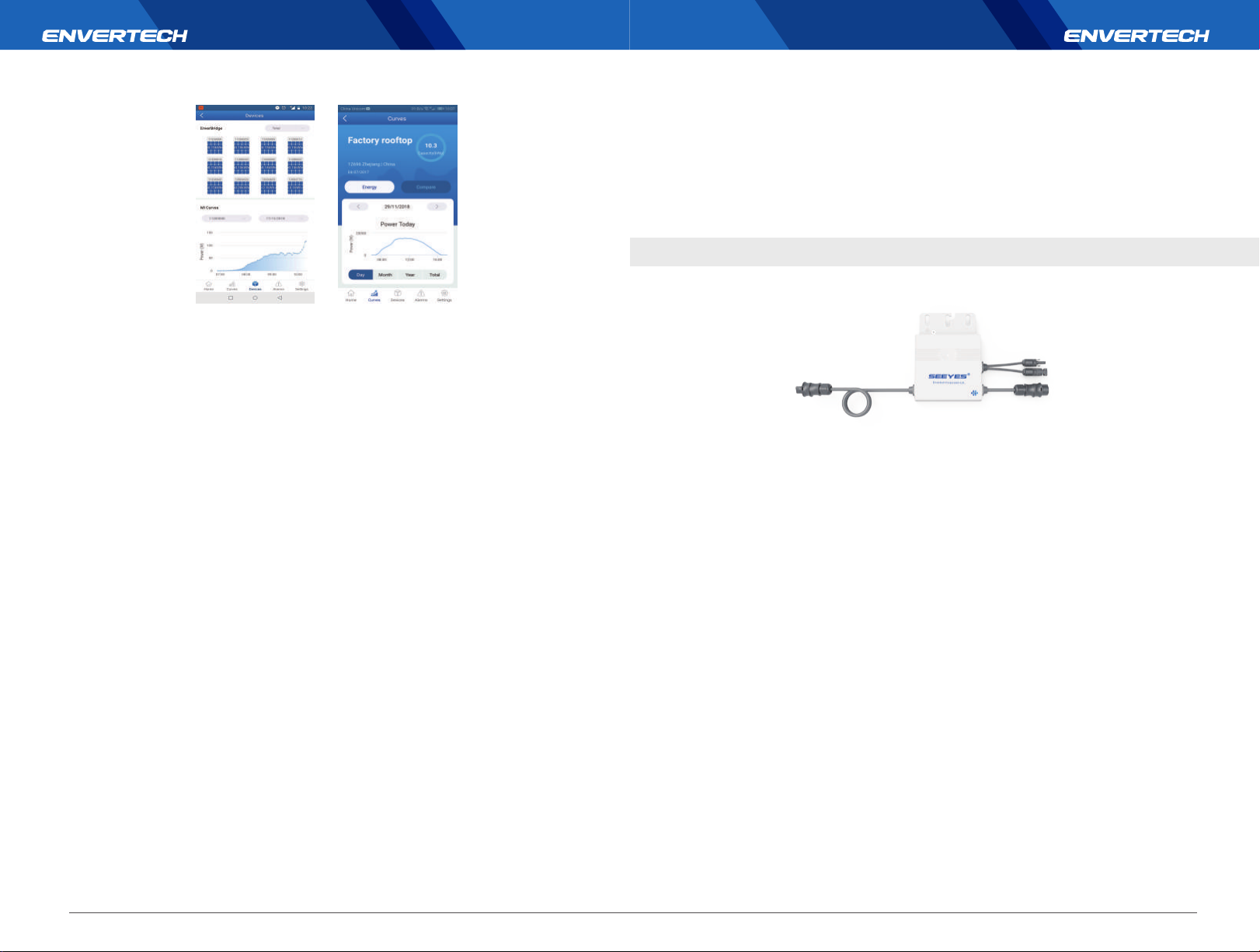
EnverView: IOS, Android App
You can view the realtime data from a web browser or Envertech app.
This integrated solar system maximizes energy harvest, increases system reliability, and
simplifies design, installation and management.
2.1 How it Works
The Envertech microinverter maximizes energy production from your photovoltaic (PV)
array. Each Envertech microinverter is individually connected to one PV module in your
array. This unique configuration means that an individual Maximum Peak Power Point
Tracker (MPPT) controls each PV module. This ensures that the maximum power available
from each PV module is exported to the utility grid regardless of the performance of the
other PV modules in the array. That is, although individual PV modules in the array may be
affected by shading, soiling, orientation, or PV module mismatch, the Envertech
microinverter ensures top performance for its associated PV module. The result is
maximum energy production from your PV system.
2.2 Monitoring Device: EnverBridge
Once you install EnverBridge and have it connected to your broadband router or
modem, Envertech microinverters automatically begin to report to EnverBridge’s
server. EnverBridge monitoring system presents bothrealtime and history performace
data.
2.3 Optimal Reliability
Microinverter systems are inherently more reliable than traditional inverters. The distributed
nature of a microinverter system ensures that there is no single point failure in the PV system.
Envertech Microinverters are designed to operate at full power at ambient temperatures as
high as +65℃(150℉). The microinverter casing is designed for outdoor installation and
complies with the IP67 protection level.
2.4 Simple Design
PV systems using Envertech microinverters are very simple to design and install. You can
install a combination of PV modules of any type, at any orientation and in any quantity. You
won’t need to install cumbersome traditional inverters. Each microinverter can be quickly
mounted on the PV rack, directly beneath each PV module. Low voltage DC wires connect
from the PV module directly to the co-located microinverter, eliminating the risk of personnel
exposure to dangerously high DC voltage.
3.Product Information
3.1 Overview
3.2 Major Characteristics
Envertech microinverters have the following characteristics which make Envertech
microinverters “Highly Efficient, Highly Reliable, Highly Cost Effective”:
Low DC input voltage.
Wide MPPT voltage range ensures high yield under various weather conditions.
High MPPT accuracy ensures minimum power loss during converting.
Complete set of protective functions.
Also, the following protective functions are integrated into Envertech microinverters:
Internal overvoltage/undervoltage protection
Faulty grounding protection
Grid monitoring
Current monitoring in grounding
DC current monitoring
EVT300 can be adapted to almost all 60-cell or 72-cell modules. Before installation, please
check the parameters of the microinverters and modules to ensure that they are
compatible.
NOTE: To ensure optimal reliability and to meet warranty requirements, the EVT300
microinverter must be installed according to the instructions in this manual.
3 4
Page 5
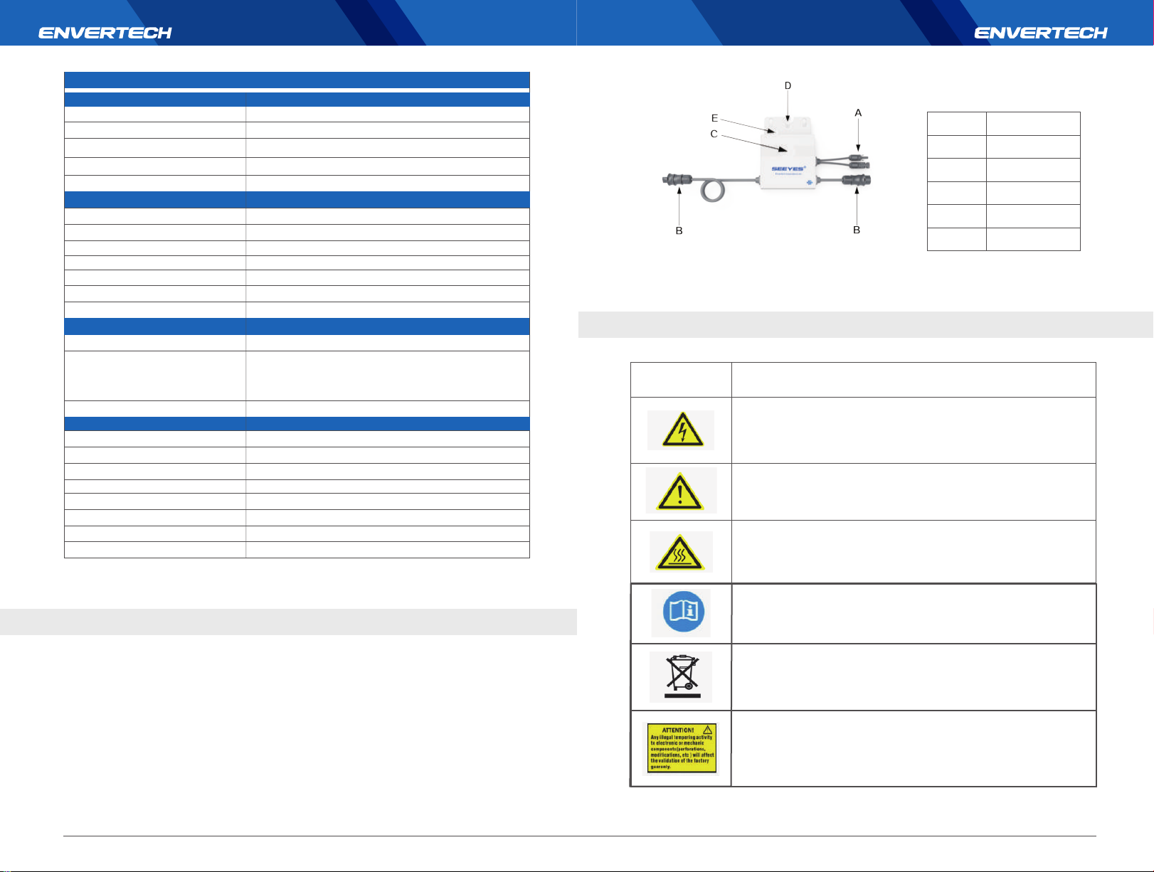
3.3 Datasheet
Model
Input Data (DC)
Max. DC Input (V)
Isc PV (Absolute Max.) (A)
Operating Range (V)
Max. Input Current (A)
MPPT Voltage Range (V)
Output Data (AC)
Normal Voltage (Vac)
Frequency (Hz)
Current (Max. continuous) (A)
Power (Max. continuous) (W)
Power Factor /Rated(default)
Total Harmonic Distortion
Maximum Units Per Branch
Features
Communication
Compliance
Lifetime
Others
Ingress Protection (IP)
Protective Class
Temperature(℃)
Relative Humidity
Overvoltage Category
Inverter Isolation
Weight
Dimensions
EVT300
54 V
15 A
18 V-54V
12A
24~45V
220V/230V
50Hz/60Hz
1.36A
300 W
>0.99
<3%
20 Units (12AWG Cable)
PLCC(Power Line Carrier Communication)
VDE-AR-N 4105、VDE0126-1-1、UTE C15-712-1、
EN50438、IEC/EN62109-1/2、IEC/EN61000、
AS4777、IEC61727、IEC61683、IEC62116
25 Years
IP 67
Class I
-40℃ to +65℃
0%~98%
OVC III (AC Main), OVC II ( PV)
□Non-isolated High frequency isolated
1.8kg
163mm*216mm*27mm
4.2 Product Description
Item Description
A
B
C
D
E
DC connectors
AC connector
LED light
Wall bracket hole
Grounding hole
4.3 Further information
If you have any further questions concerning accessories or installation, please check our
website www.envertec.com or send an email to [email protected].
5.Planning of Microinverter Installation
5.1 Symbols on Inverter
Symbol
Description
Dangerous electrical voltage
This device is directly connected to public grid, thus all work related to
theinverter shall only be carried out by qualified personnel.
NOTICE, danger!
This device directly connected with electricity generators and public grid.
Danger of hot surface
The components inside the inverter will release a log of heat during
operation. DO NOT touch aluminum casing during operating.
4.Packing checklist
4.1 Accessories
After you receive the Envertech microinverter, please check if there is any damage on the
carton, and then check the inside completeness for any visible external damage on the
microinverter and accessories. Contact your dealer if anything is damaged or missing.
5
An error has occurred
Please go to Chapter 10 “Trouble Shooting” to repair the error.
This device SHALL NOT be disposed of in residential wastePlease go to
Chapter 9 “Recycling and Disposal” for proper treatments.
No unauthorized perforations or modifications
Any unauthorized perforations or modifications are strictly forbidden. If any
defect or damage (device/person) is occurred, Envertech shall not take any
responsibility for it.
6
Page 6
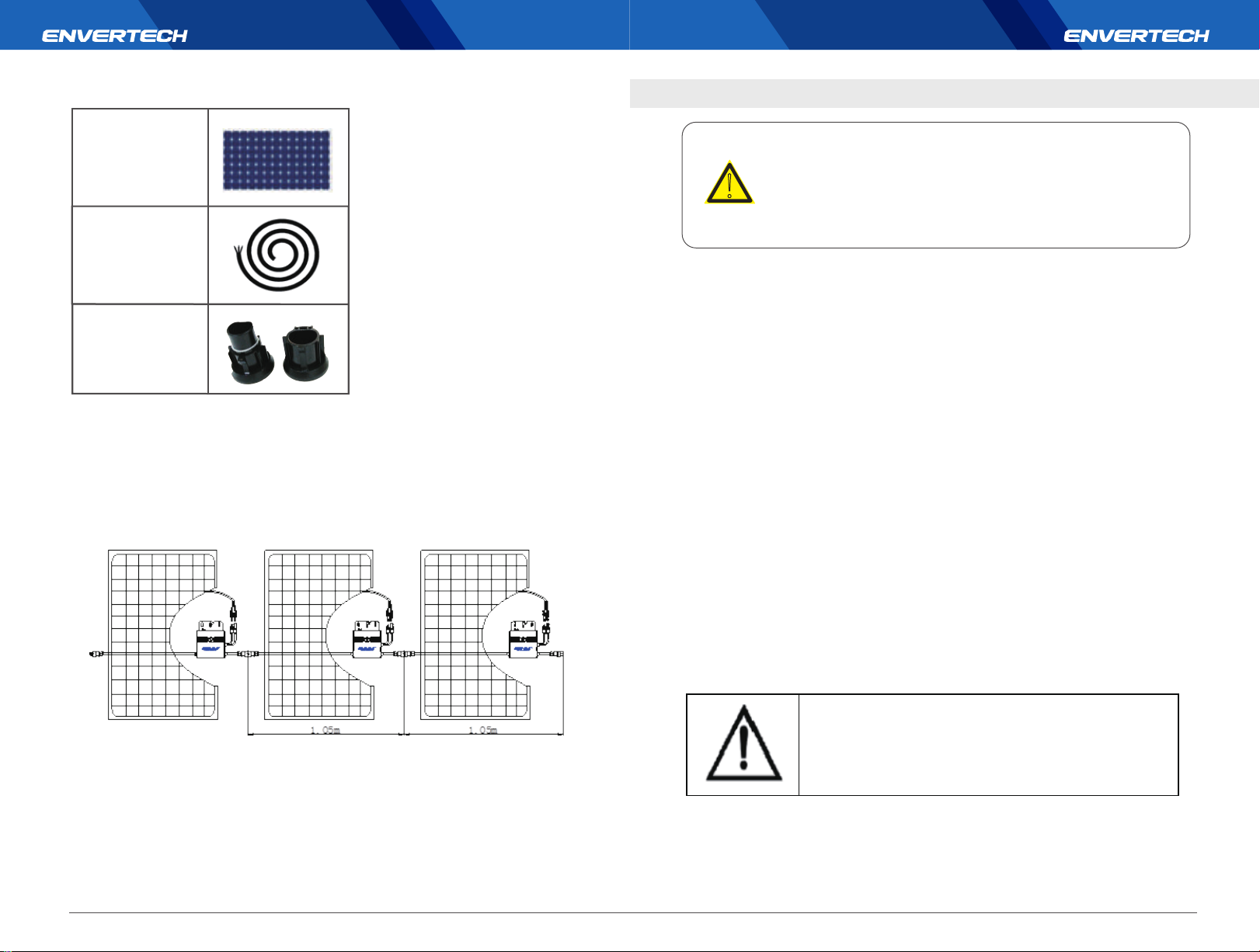
5.2 Accessories
6. Microinverter System Installation
PV Modules
AC extension cable
(AWG12 or above)
AC End Cap
5.3 Cable Model Selection
To install the AC Bus Cable, you just simply unroll the cable to the needed length to make the
cut. Directly connect the AC Bus Cable to the junction box of the branch. Seal the other
cutting end with the end cap to make it isolated from the environment. You should choose
the type of AC Bus Cable according to the orientation of PV module. We suggest the
following type of cable:
WARNING
Only qualified personnel may connect the Envertech
!
microinverter to the utility grid after receiving prior approval from
the electrical utility company.
Installing Envertech microinverter system involves several key steps. Each step listed here
is elaborated on the following pages.
Step 1: Mount microinverters onto the rack
Step 2: Grounding
Step 3: Connect microinverters’ AC cables serially
Step 4: Fasten AC cables
Step 5: Seal the unused connector of the AC cable
Step 6: Connect the AC cable to the junction box
Step 7: Mount EnverBridge
Step 8: Prepare AC extension cable
Step 9: Connect PV modules to microinverters
Step10: Switch on the PV system
You must install the microinverter system under connection
neither to the grid nor to the PV modules (or if not
disconnected, the modules should be shaded)
7 8
Page 7
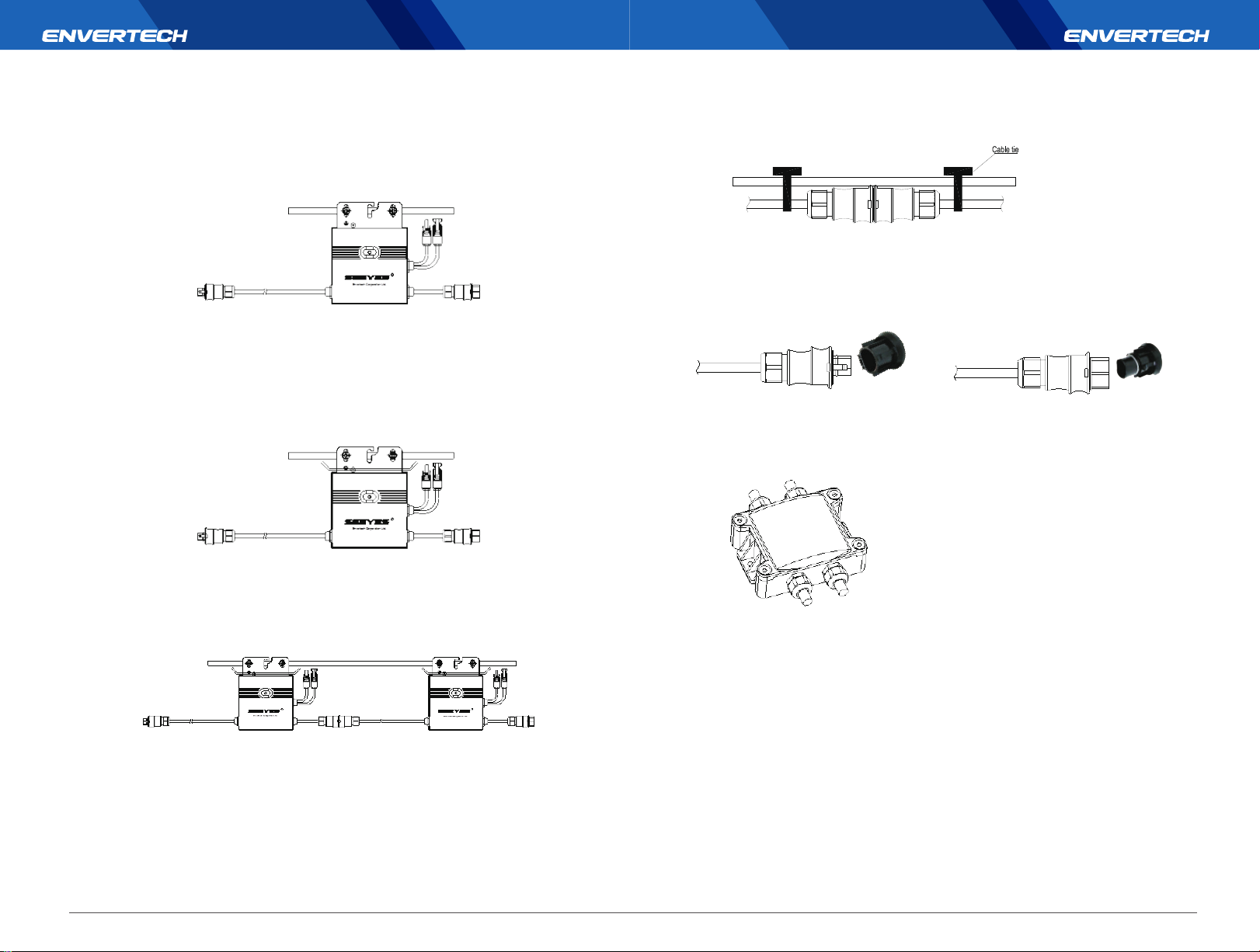
Step 1:Mount microinverters onto the rack
Mark out the estimated center of each PV module on the rack to facilitate locating microinverters..
Mount all microinvertes under modules to avoid rain and sun, with the trademark facing
downward.
Step 2: Grounding
Microinverters and modules must be connected to grounding conductor in accordance with
national standards.
Fix the grounding wire with screws to the microinverter’s grounding hole, so that the grounding of
microinverters can be realized.
Step 4: Fasten AC cables
Fasten AC cables and grounding cables to the rack with cable ties.
Step 5: Seal the unused connector of AC cable.
Insert the end cap directly into the connector on the unused end, and check if it is inserted
in place.
Step 6: Connect AC cable to the junction box
Connect AC cable to the input of the junction box.
Step 3: Connect microinverter AC cables serially
Connect the AC connectors on both sides of microinverters in a hand-in-hand way.
9 10
Page 8
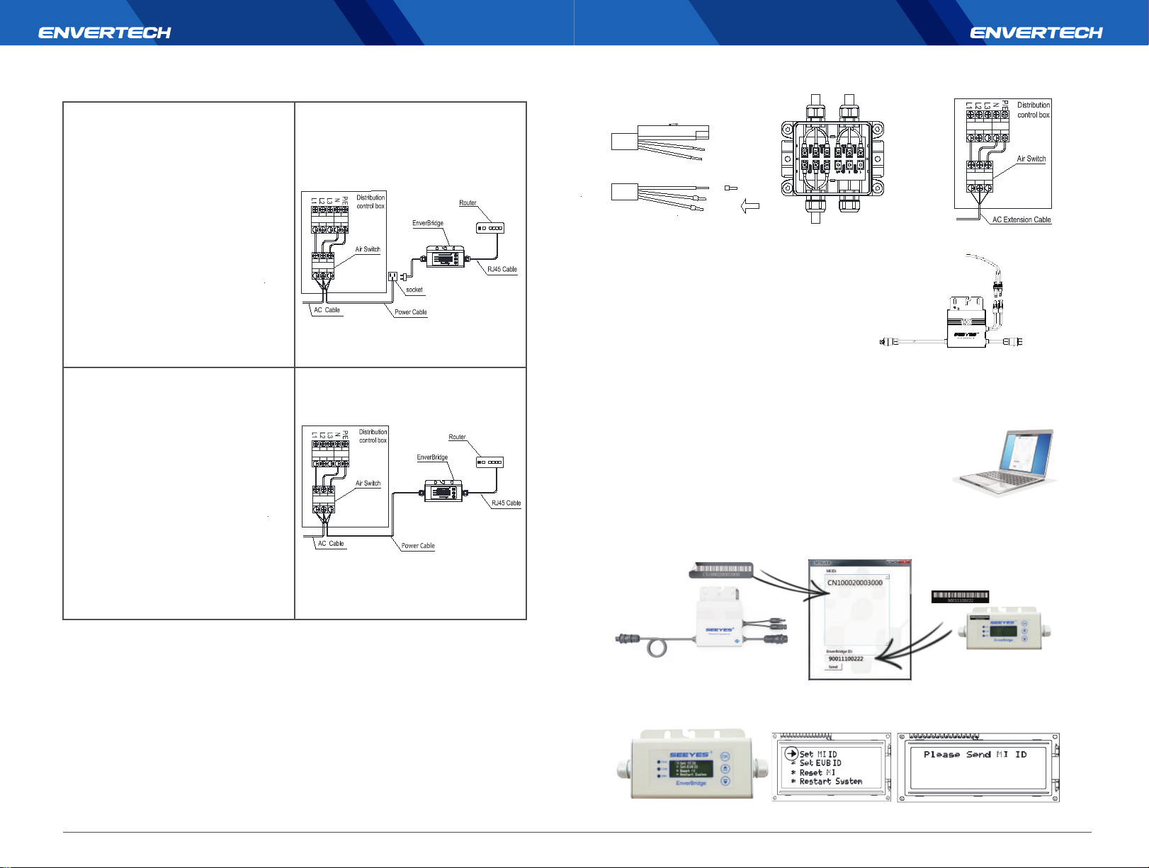
Step 7: Mount EnverBridge
Option 1: Indoor installation(I)
1. Turn off the air switch and connect
EnverBridge to the socket. This operation
should be done under the instruction of
professionals.
2. Fix EnverBridge at proper position in or close
to the distribution box;
3. Open the cover on the right side of
EnverBridge. Set RJ45 cable through the
waterproof connector and connect it to the
network input. Close the cover and recheck if
it’s completely sealed;
4. Run the RJ45 cable and connect the other
side to your router;
5. Put the EnverBridge plug into the socket.
Option 2: Indoor installation(II)
1. Open the cover on the right side of
EnverBridge. Set RJ45 cable through the
water proof connector and connect it to he
network input. Close the cover and recheck if
it’s completely sealed;
2. Run the RJ45 cable and connect it to your
router;
3. Fix EnverBridge at proper position in or
close to the distribution box;
4. Turn off the air switch and connect
EnverBridge’s power cable to the air switch.
This operation should be done under the
instruction of professionals.
1 2 3
x=14mmR
AC Extension Cable
Step 9: Connect PV modules to
microinverters
Mount the PV modules on top of
microinverters;
Connect each PV module with the DC
input cables of the microinverter.
Step 10: Switch on the PV system
Ensure all connection is completed and then turn on the air switch.
Step 11: Monitoring through EnverPortal
1. EVB202 MI Binding
1) Please visit the Download Center on our website
www.envertec.com and download Set ID exe. in your computer.
Open the software as below.
2) Please make sure your EVB202 is connected to the same router as your computer is
connected to. And use the scanner to scan or manually input the EVB202 ID and the inverter IDs
into the software as below.
Step 8: Prepare AC extension cable.
It is suggested to use extension cable of AWG12 above (same or higher than Envertech AC
cable standard).
1. Remove the skin of the two ends of the extension cable by y=40mm and remove the skin of
internal wires by x=14mm. Set the metal terminals onto the open parts and clamp them to
tighten the connection;
2. Connect one side of the extension cable to the junction box;
3. Connect the other side of the extension cable to the air switch.
11 12
3) Please press [Set MI ID], you will see the content shown as below.
Page 9
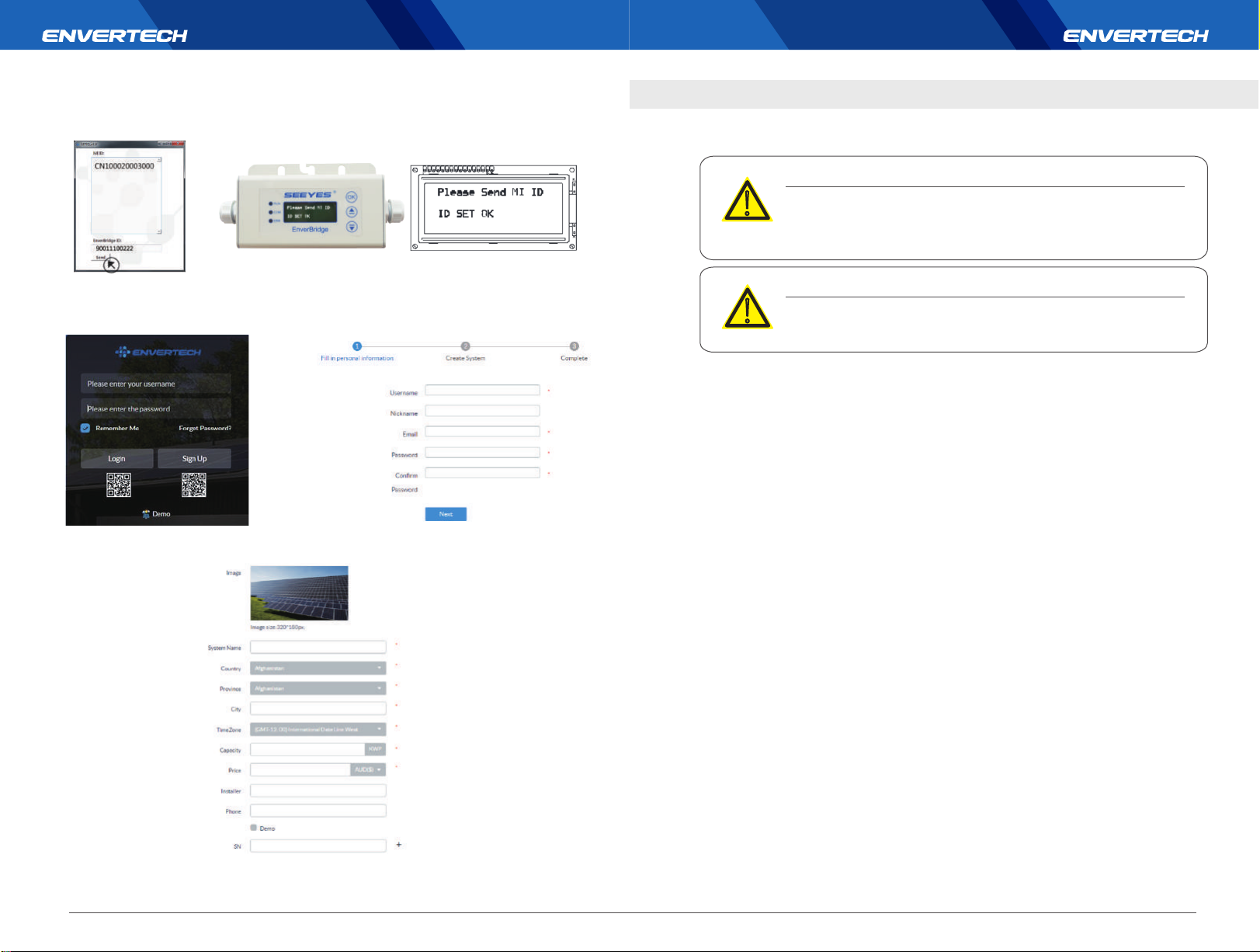
4) Then you can press “Send” button in the software to complete the setting. Meanwhile, “ID Set
OK” will be also shown on the EVB202 screen. Thus the MI binding process is completed.
7. Debugging and Operating
Please notice the symbols.
WARNING
Only qualified personnel may connect the Envertech
!
microinverter to the utility grid after receiving prior approval from
the electricalutility company.
2. Register a new account. Click sign up.
Visit www.envertecportal.com.
4. Click next and create your system. SN is your EnverBridge number which is mandatory.
3. Fill in the account information.
WARNING
Ensure that all AC and DC wiring is correct. Ensure that none of
!
the AC and DC wires is twisted or damaged.
7.1 Energize the System
1. Turn on the switch or the circuit breaker at each microinverter AC branch.
2. Turn on the main AC circuit breaker in the distribution box. Your system will start to
produce power after 3 minutes.
3. Envertech microinverters begin to communicate through the power lines to
EnverBridge. The entire system will be detected within 10 minutes.
4. The voltage and frequency of EVT300 can be adjusted on the site. If adjustments are
required by your local utility company, installers can use EnverBridge to manage grid
parameters after all microinverters have been detected.
7.2 EVT300 Operation
The Envertech microinverter is powered on when there is sufficient DC voltage from the
PV module. The LED light of each microinverter will blink green to indicate normal
start-up operation approximately 1 minute after DC power is applied.
You can find more information on the user manual for EnverBridge.
1413
Page 10
8.Troubleshooting and Maintenance
Adhere to all the safety measures described throughout this manual. If the PV
system does not operate correctly, the following troubleshooting measures
can be applied by qualified personnel.
WARNING
Do not attempt to repair the Envertech microinverter.It contains
no user-serviceable parts. If the microinverter fails, contact your
!
direct supplier or Envertech customer service to obtain an RMA
(return merchandise authorization) number and start the
replacement process.
WARNING: The AC and DC connectors on the cabling are rated as a disconnecting point only
when used with an Envertech microinverter.
WARNING: Envertech microinverters are powered by DC power from the PV modules.
Please disconnect and reconnect DC power to check the LED blinks 1 minute after DC is
applied.
1. Make sure AC breakers are on.
2. Check the connection to the utility grid and verify that the grid voltage is within allowable
ranges shown in the Technical Data section.
3. Verify that AC voltage at all solar power circuit breakers of the load centers are within the
ranges shown in the following table.
4. Verify that AC line voltage at the junction box for each AC branch circuit is within the ranges
required by local grid standards.
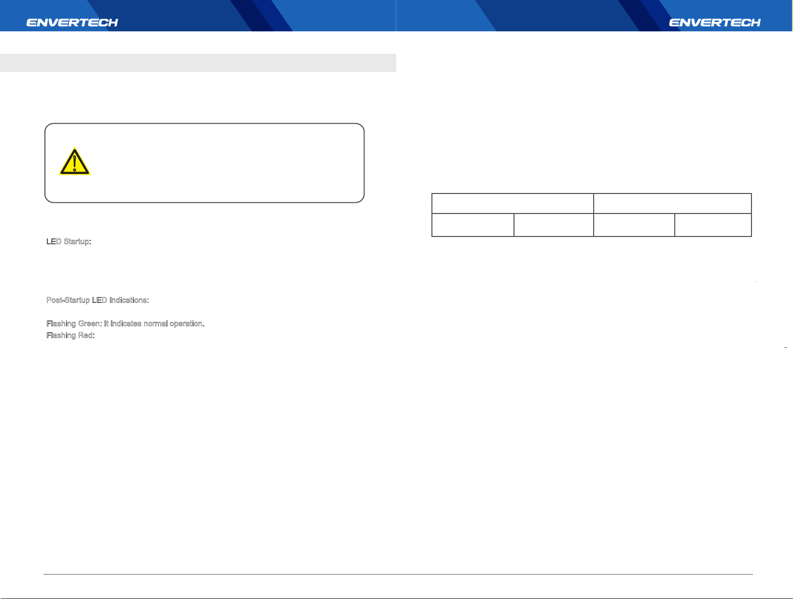
Single-Phase 230 VAC
Three-Phase 230 VAC
8.1 LED Status Indications and Error Report
LED Startup:
The LED of each microinverter blinks red for a while at the beginning, and then blinks green
to indicate normal start-up approximately 10 seconds after DC power is applied. If the LED
blinks red after DC power is on , it indicates a failure during the start-up.
Post-Startup LED Indications:
Check LED status to confirm the present situation.
Flashing Green: It indicates normal operation.
Flashing Red:
1. If red light flashes every 2 or 3 seconds, it indicates that the microinverter is waiting for sun
or prepare to produce energy.
2. If red light flashes continuously, it indicates that the microinverter is not operating normally.
The microinverter does not detect that the utility grid is within operable voltage/frequency
range. The microinverter cannot produce power until this is solved.
8.2 Troubleshoot an Inoperable Microinverter
To troubleshoot an inoperable microinverter, follow the steps in the order shown below.
WARNING: Be aware that only qualified personnel should troubleshoot the PV array or the
Envertech microinverter.
Best Practice: Please do not disconnect DC connection while the system is working. Ensure
that no current is flowing in the DC wires prior to disconnecting. If necessary, use an opaqueto
cover the PV module prior to disconnecting the PV module. Always disconnect AC power
before disconnecting the PV module from the Envertech microinverter. Disconnecting AC
connectors of the microinverters is also a means of cutting off AC power.
L to N 180 to 265VAC L1 to L2 to L3 310 to 460VAC
5. Confirm if the microinverter side is connected to the grid by measuring the voltage from AC
line to line and line to neutral.
6. Visually check if AC branch circuit connection is correctly done. Reinstall if
necessary.Check also for damage, such as rodent damage.
7. Make sure that all circuit breakers are off.
8. Disconnect and re-connect the PV modules’ DC connectors with microinverters. The LED
status of each microinverter will blink green to indicate normal start-up operation soon after
DC power is applied (less than one minute).
9. Attach an ammeter clamp to one conducting wire of the DC cables from the PV module to
measure the microinverter’s current. This will be under 1 Amp if AC is disconnected.
10. Check the DC connection between the microinverter and the PV module. The connection
may need to be tightened or reseated. If the connection is worn out or damaged, it needs
replacement.
11. Verify with your utility company that grid frequency is within the regulated range.
8.3 Disconnect Microinverters from PV Modules
If your problems are still unsolved with the steps above, please contact Envertech tech
support through www.envertec.com. If Envertech approves the replacement, please take off
the microinverter according to the following instructions. In order to ensure the disconnection
between the microinverter and the PV Module will not be done while the microinverter is at
working status, , please strictly follow the steps below.
1. Turn off AC branch circuit breaker.
2. Disconnect the microinverters in the following procedure:
Pull the AC connectors of both sides of the microinverters in the opposite direction with
appropriate force.
15
16
Page 11
3. Cover the PV module with an opaque, and then disconnect the PV module DC connectors
from the microinverter.
4. Loosen the grounding screw and remove the grounding wire.
5. Take off the microinverter from the PV frame.
Do not leave the AC connectors open for a long time. All
unused connectors must be covered by sealing caps.
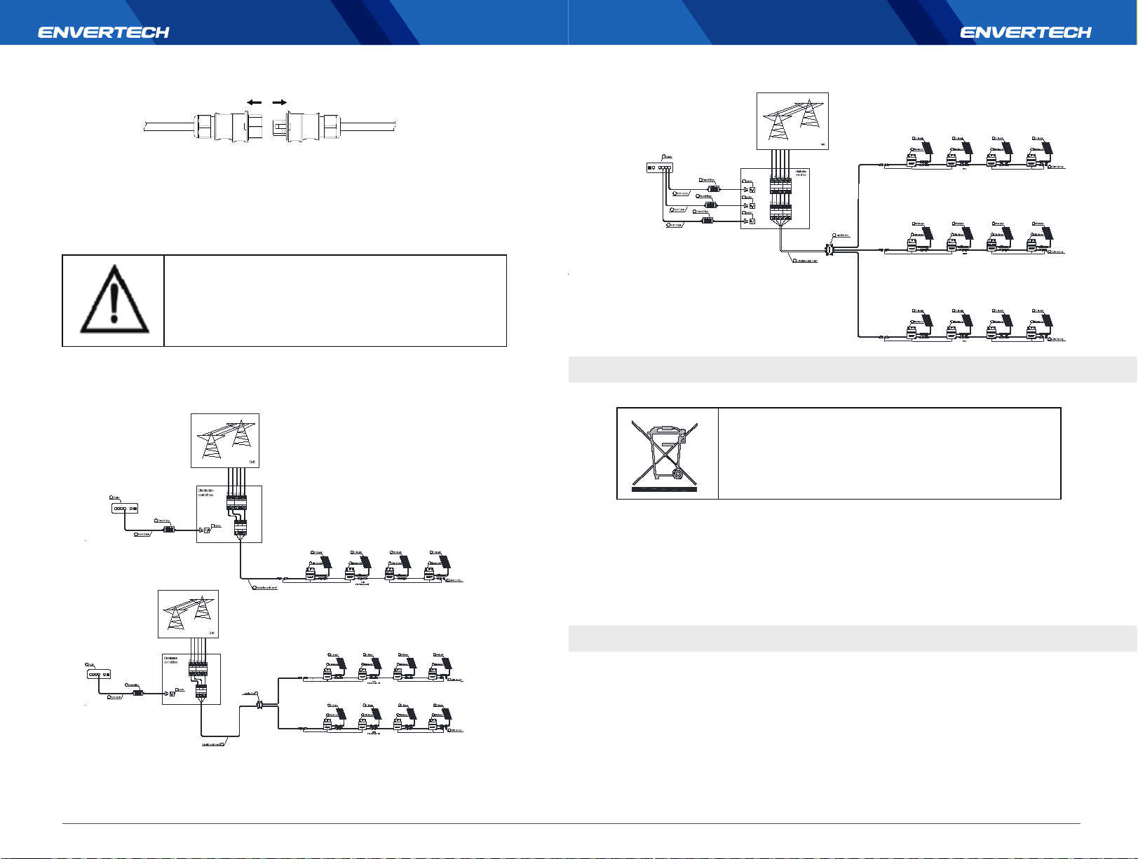
9. System Diagram
1. Single phase:
7
6
4
9
1
1
1
2
2
length 746 mm
8
length 1050 mm
1
2
2
length 304 mm
3
length 1050 mm
2. Three phase:
1
2
length 1050 mm length 304 mm
1
2
length 1050 mm
1
2
length 1050 mm
2
2
length 304 mm
2
length 304 mm
1
3
1
3
1
3
1
1
2
7
6
4
6
4
6
4
9
9
9
5
8
length 746 mm
length 746 mm
length 746 mm
2
length 1050 mm
Microinverter(n=17)
1
1
2
2
length 1050 mm
Microinverter(n=17)
1
1
2
2
length 1050 mm
Microinverter(n=17)
10. Recycling and disposal
WARNING
This device cannot be disposed in a household trash can.
In order to comply with the regulations on recycling management of electrical and
electronic wastes in various countries, electrical equipments that have reached its lifetime
must be collected separately to the unit or individual that has obtained the qualification for
disposing discarded electrical and electronic products. For any equipment that you no
longer use, please return it to your dealer for recycling, or send it to an approved recycling
unit in your area for recycling.
17
1
1
2
7
6
4
9
5
8
2
length 746 mm
length 1050 mm
1
1
2
2
length 746 mm
length 1050 mm
1
2
2
3
length 304 mm
length 1050 mm
1
1
2
2
3
length 1050 mm
length 304 mm
Zhejiang Envertech Corporation Ltd.
Tel: +86 579 8926 6326 Web: www.envertec.com Email:[email protected]
Add:24th Floor, Jintong Mansion, Center of Headquarters, Yongkang City,
Zhejiang Province, China
18
1
11. Contact
 Loading...