

Page 1
www.envertec.com
EVT500
MICROINVERTER
User Manual
Zhejiang Envertech Corporation Ltd.
Add:24th Floor, Jintong Mansion,
Center of Headquarters, Yongkang City,
Zhejiang Province, China
Page 2

Content
1. Important Safety Information..........................................................................
1.1 Read it First.............................................................................................
1.2 Safety Instructions.................................................................................................
2. Envertech Microinverter System.........................................................
2.1 How it Works...........................................................................................
2.2 Monitoring Device: EnverBridge..............................................................
2.3 Optimal Reliability....................................................................................
2.4 Simple Design........................................................................................
3. Product Information..............................................................................
3.1 Overview..................................................................................................
3.2 Major Characteristics...............................................................................
3.3 Datasheet................................................................................................
4. Packing checklist..................................................................................
4.1 Accessories.............................................................................................
4.2 Product Description.................................................................................
4.3 Further information..................................................................................
5. Planning of Microinverter Installation.................................................
5.1 Symbols on Inverter.................................................................................
5.2 Lightning and Surge Suppression...........................................................
6. Microinverter Installation......................................................................
6.1 Tool Required...........................................................................................
6.2 Necessary parts for Installation................................................................
6.3 Installation Steps.....................................................................................
6.4 CableAssembly........................................................................................
7. Debugging and Operaing......................................................................
7.1 Energize the System...............................................................................
7.2 EVT500 Operation...................................................................................
8. Troubleshooting and Maintenance......................................................
8.1 LED Status Indications and Error Reporting...........................................
8.2 Troubleshoot an Inoperable Microinverter...............................................
8.3 Microinverter Maintenance......................................................................
9. Contact...................................................................................................
1
1
1
2
3
3
4
4
4
4
4
5
6
6
6
6
6
6
7
7
7
7
8
9
10
11
11
11
11
12
13
14
Page 3
1.1 Read it First
This manual contains important instructions for installation and maintenance of the
EVT500 microinverter.
To reduce the risk of electrical shock, and to ensure safe installation and operation of
the microinverter, the following safety symbols appear throughout this document to
indicate dangerous conditions and important safety instructions.
The Envertech microinverter system is an on-grid microinverter system with world
top-class technology. This manual gave details about safe installation and operation
of the Envertech Microinverter.
The three key elements of an Envertech microinverter system include :
Do not use Envertech equipment in a manner not specified by the manufacturer. Doing so may cause
death or injury to persons, or damage to equipment.
Be aware that only qualified personnel should install or replace the Envertech microinverters and the
Cable and accessories.
Do not attempt to repair the Envertech microinverter; it contains no user-serviceable parts. If it fails,
contact Envertech customer service to start the replacement process. Tampering with or opening the
Envertech microinverter will void the warranty.
If the AC cable on the microinverter is damaged or broken, do not install the unit.
Before installing or using the Envertech microinverter, read all instructions and cautionary markings in
the technical description and on the Envertech microinverter system and the PV equipment.
Connect the Envertech Microinverter to the utility grid only after you have completed all installation
procedures and after receiving prior approval from the electrical utility company.
Be aware that the body of the Envertech microinverter itself is aheat sink. Under normal operating
Conditions, the temperature is 20°C above ambient, but under extreme conditions the microinverter
can reach a temperature of 65°C (176°F). To reduce risk of burns, use caution when working with
microinverters.
Do not disconnect the PV module from the Envertech microinverter without first removing AC power.
Be aware that the EVT500 has the ability to auto adjust voltage and frequency according to the
settings based on local standards. Only an authorized installer who has got permission from local
Electrical utility and meets with the following requirements shall be allowed to set the Envertech
microinverter.
2.Envertech Microinverter System
1.2 Safety Instructions
1 2
!
WARNING
DANGER
DANGER indicates a hazardous situation which, if not avoided,
will result in death or serious injury.
WARNING indicates a hazardous situation which, if not avoided,
can result in death or serious injury or moderate injury.
NOTICE indicates a situation that can result in property damage,
if not avoided.
!
NOTICE
!
1.Important Safety Information
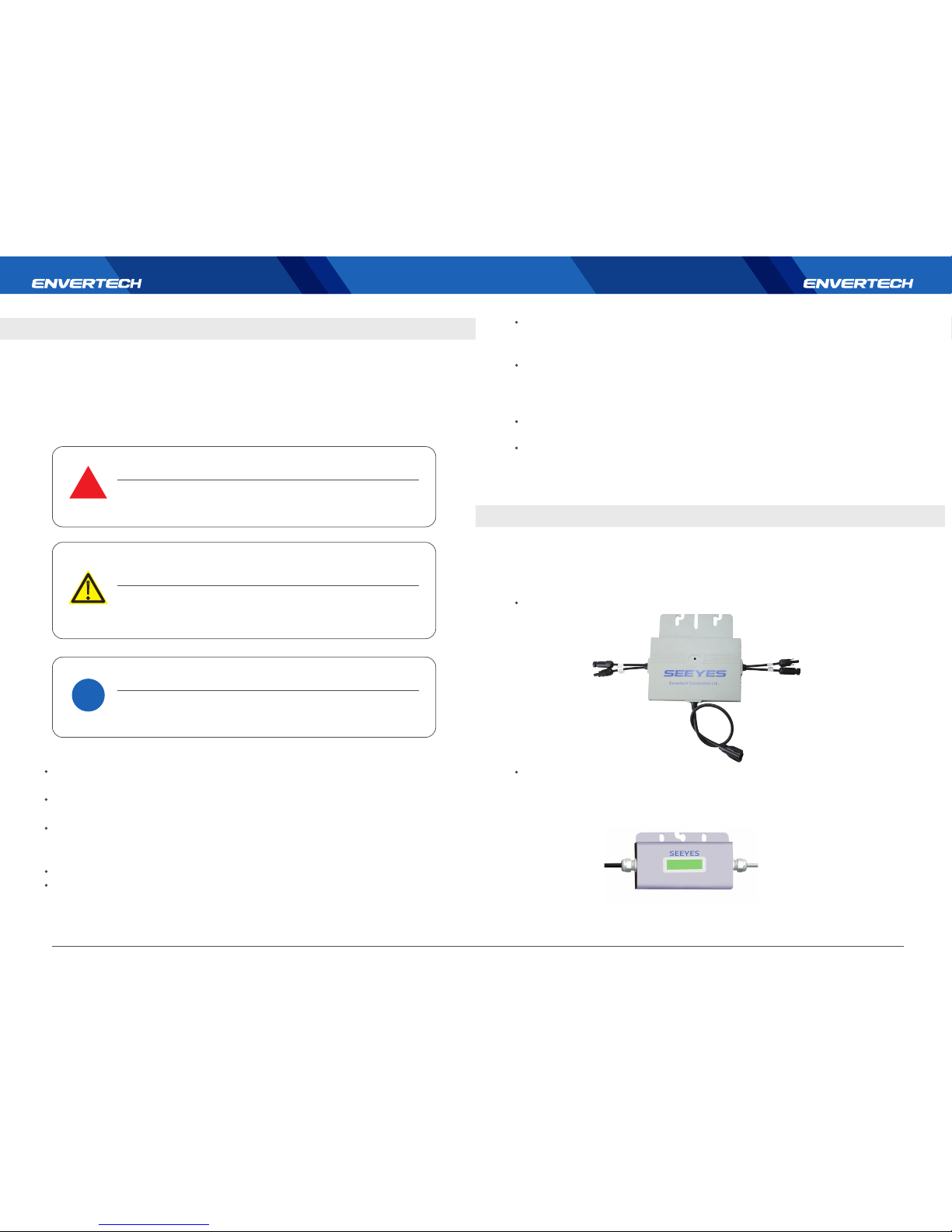
EnverBridge: monitoring and communication device.
EVT500 microinverter
Page 4
3.Product Information
2.1 How it Works
The Envertech microinverter maximizes energy production from your photovoltaic (PV) array. Each
Envertech microinverter is individually connected to one PV module in your array. This unique
configuration means that an individual Maximum Peak Power Point Tracker (MPPT) controls each
PV module. This ensures that the maximum power available from each PV module is exported to the
utility grid regardless of the performance of the other PV modules in the array. That is, although
individual PV modules in the array may be affected by shading, soiling, orientation, or PV module
mismatch, the Envertech microinverter ensures top performance for its associated PV module. The
result is maximum energy production from your PV system.
3.1 Overview
3.2 Major Characteristics
Envertech microinverter has the following characteristics which make Envertech microinverter
“High Efficient, High Reliable, High Cost Effecient”
Once you install EnverBridge and provide an ethernet connection to your broadband
router or modem, the Envertech microinverter automatically begin reporting to the
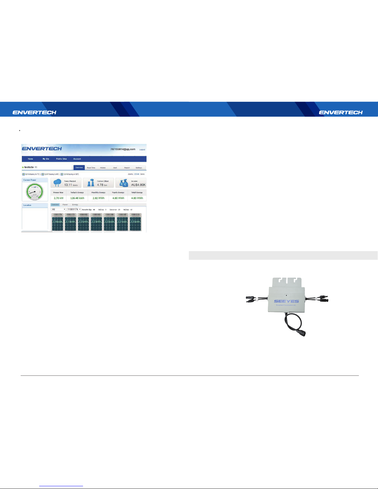
Envertech EnverBridge web server. The EnverBridge software presents current and
historical system.
performance trends, and it informs you of PV system status.
Microinverter systems are inherently more reliable than traditionalinverters. The distributed nature
of a mMicroinverter system ensures that there is no single point failure in the PV system. Envertech
mMicroinverters are designed to operate at full power at ambient temperatures as high as +65
℃(150℉). The Microinverter casing is designed for outdoor installation and complies with the IP65
protection level.
IP65 rating definition: IP stands for 'Ingress Protection'. An IP number is used to specify the environ-
mental protection of enclosures around electronic equipment. It is composed of two numbers, the
first referring to the protection against solid objects and the second against liquids. The higher the
number, the better the protection. 6 means totally protected against dust. 5 means protected
against low pressure water jets from any direction.
NOTE: To ensure optimal reliability and to meet warranty requirements, the Envertech microinverter
must be installed according to the instructions in this manual.
PV systems using Envertech microinverters are very simple to design and install. You can install a
combination of PV modules of any type, at any orientation and in any quantity. You won’t need to
install cumbersome traditional inverters. Each microinverter can be quickly mounted on the PV
racking, directly beneath each PV module. Low voltage DC wires connect from the PV module directly
to the co-located microinverter, eliminating the risk of personnel exposure to dangerously high DC
voltage.
2.4 Simple Design
3 4
2.2 Monitoring Device: EnverBridge
2.3 Optimal Reliability
EnverPortal: data display and analysis web platform.
Page 5
Wide DC input voltage range and current range.
Wide MPPT voltage range ensures high yield under various weather conditions.
High MPPT accuracy, ensures the minimum power loss during converting.
Complete set of protection functions.
Also,the following protection functions are integrated in Envertech microinverter:
Internal overvoltage/undervoltage
Faulty Grounding protection
Grid monitoring
Ground overcurrent monitoring
DC current monitoring
3.3 Datasheet
4.Packing checklist
After you receive the Envertech microinverter, please check if there is any damage on the
carton, and then check the inside completeness for any visible external damage on the
microinverter and accessories. Contact your dealer if anything is damaged or missing.
5 6
5.Planningof Microinverter Installation
4.1 Accessories
4.2 Product Description
If you have any further questions concerning accessories or installation, please check our
website www.envertec.com or send an email to [email protected]
4.3 Further information
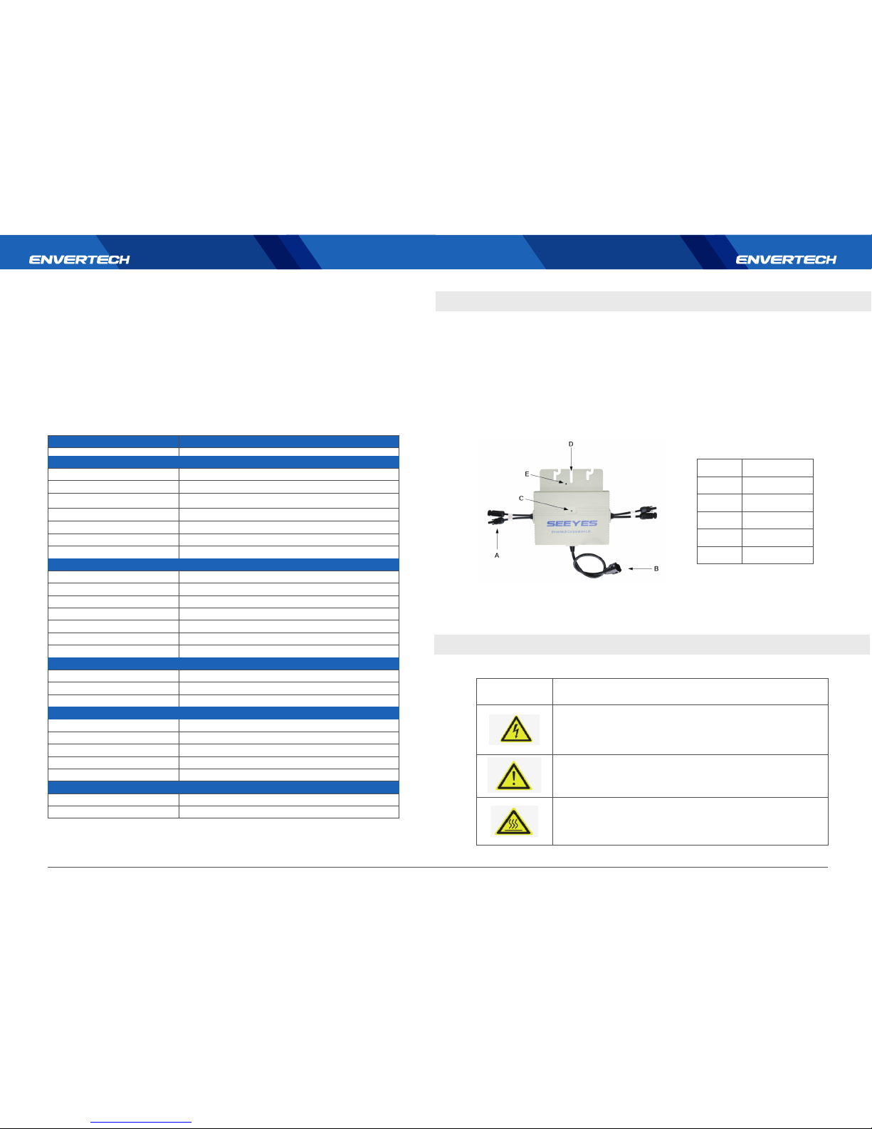
Item Description
A
B
C
D
E
DC connectors
AC connector
LED light
Wall bracket hole
Grounding hole
Symbol
Description
Dangerous electrical voltage
This device is directly connected to public grid, thus all work related to
theinvertershall only be carried out by qualified personnel.
NOTICE, danger!
This device directly connected with electricity generators and public grid.
Danger of hot surface
The components inside the inverter will release a log of heat during
operation. DO NOT touch aluminum casing during operating.
Model
Input Data (DC)
Recommended maximum input
Maximum input DC voltage
Start voltage
Peak power tracking range
Operating range
Maximum DC short circuit current
Maximum input current
Output Data (AC)
Rated output power
Nominal voltage
Nominal frequency
Power factor
Total Harmonic Distortion
Maximum units per branch
Efficiency
Peak inverter efficiency
Nighttime power consumption
Mechanical Data
Enclosure environmental rating
Ambient temperature range
Operating temperature range
Dimensions (WxHxD)
Communication
Warranty
Maximum output current
EURO weighted efficiency
Weight 2.4Kg
EVT500
300W*2
54V
24V
28V~42V
18V~54V
15A
9.5A*2
500W
2.17A
220V/230V/240V
50Hz/60Hz
>0.99
<3%
8
95.8%
95.1%(according to the EN50530)
IP65
-40℃~+85℃
-40℃~+65℃
248mm*172mm*27.5mm
自然冷却
25 Years
PLCC
Features
120mW
5.1 Explanations of Symbols on Inverter
Page 6
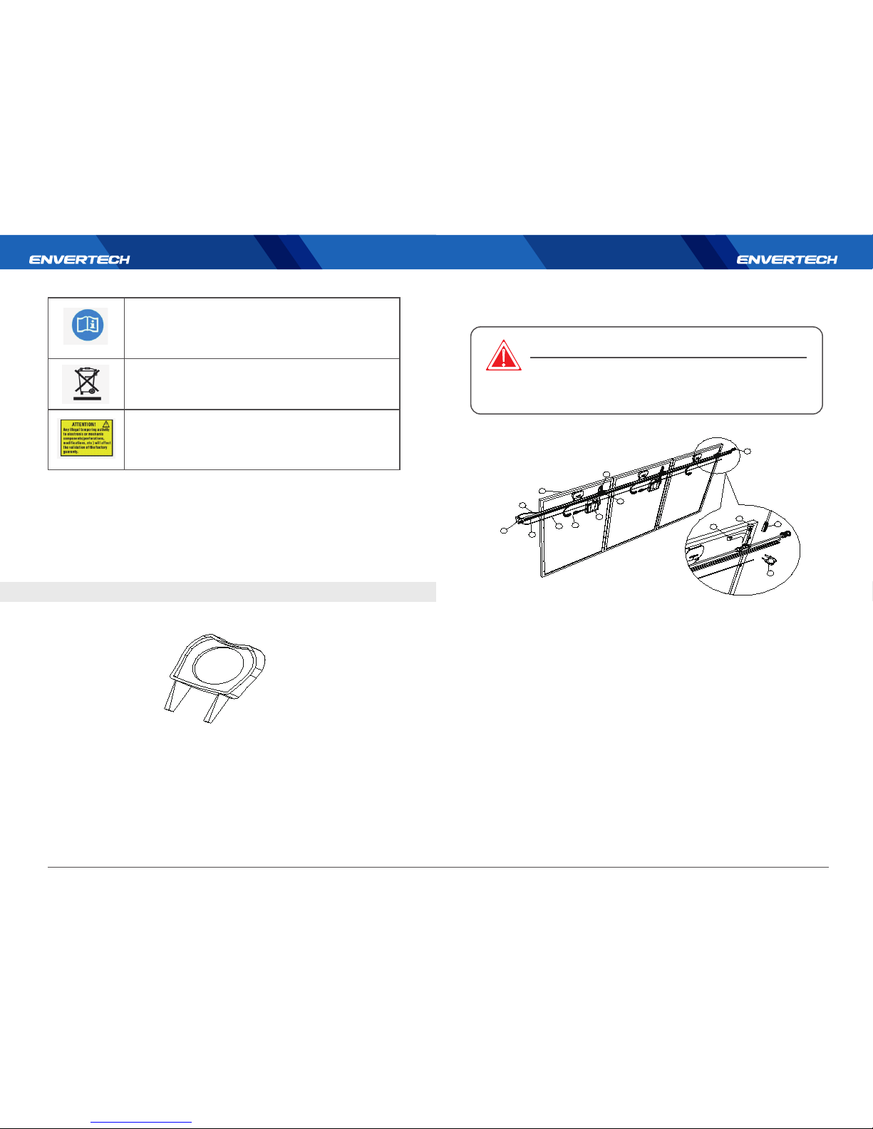
6.Microinverter Installation
Envertech microinverters have integral surge protection. However, if the surge has
excess energy, the protection built into the microinverter can be exceeded, and the
equipment can be damaged. For this reason, Envertech recommends that you protect
your system with lightning and/or surge suppression devices. In addition to having some
level of surge suppression, it is important to have insurance that protects against
lightning and electrical surges.
Installing the microinverter system involves several key steps. Each step listed here is
detailed in the following page.
01 PV module
02 Microinverter
03 Mounting racking
04 AC BUS Cable
05 AC Extension Cable
06 AC Trunk Plug Tag
07 AC Trunk End Cap
08 AC Trunk Unlock Tool
5.2 Lightning and Surge Suppression
6.1 Tool Required
6.2 Necessary parts for Installation
6.3 Installation Steps
7 8
An error has occurred
Please go to Chapter 10 “Trouble Shooting” to repair the error.
This device SHALL NOT be disposed of in residential wastePlease go to
Chapter 9 “Recycling and Disposal” for proper treatments.
No unauthorized perforations or modifications
Any unauthorized perforations or modifications are strictly forbidden. If any
defect or damage (device/person) is occurred, Envertech shall not take any
responsibility for it.
05
12
04
03
06
11
09
10
08
07
01
02
08
13
Step1:Position AC BUS cable.
Step2:Fix the microinverter to the rack appropriate to the locations of BUS cable connectors. After
that, fasten AC BUS cable to the rack with cable ties.
Step3:Connect AC cables.
Step4:Terminate the unused end of AC BUS cable with the AC Trunk end cap.
Step5:Mount EnverBridge, connect AC BUS cable to Enverbridge with AC extension cable and
connect EnverBridge to the distribution grid.
Step6:Mount PV panels on the racking system and connect DC leads to the microinverters.
Step7:Place the labels on the EVT500 installation diagram to identify the location of each microin-
verter.
Step8:Energize the system by turning on the breaker in the distribution panel. Then you are
welcome to visit our energy and monitoring website EnverPortal to enjoy the performance of your
solar system.
DO NOT connect or disconnect the PV module and Envertech
Microinverter without first removing AC power from the PV
system.
!
DANGER
Page 7
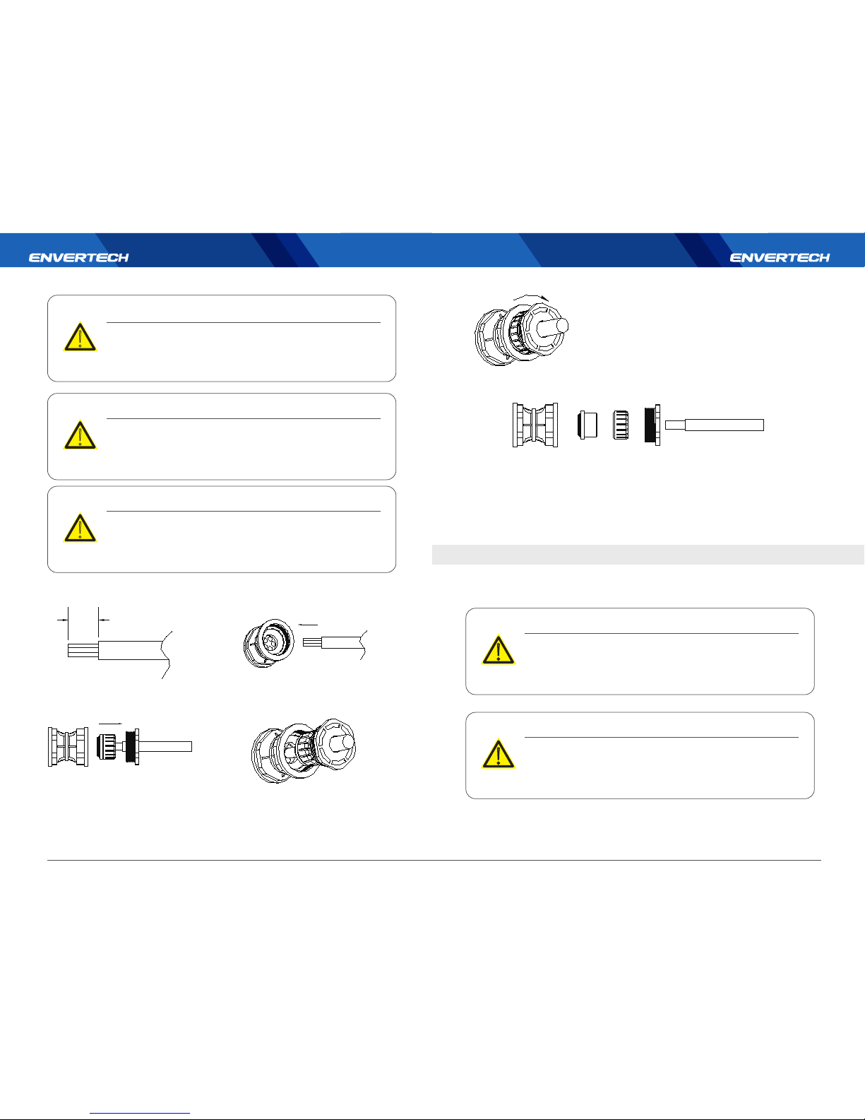
Allow a minimum of 1.9cm between the roof and the bottom of the
microinverter. Also allow 1.3cm between the back of the PV module
and the top of the microinverter.
You must install the microinverter under the module, out of rain and
sun. Do not mount the microinverter in a position that allows
long-term exposure to direct sunlight or in a vertical orientation that
allows water to collect in the DC connect part.
7.Debugging and Operating
Note:
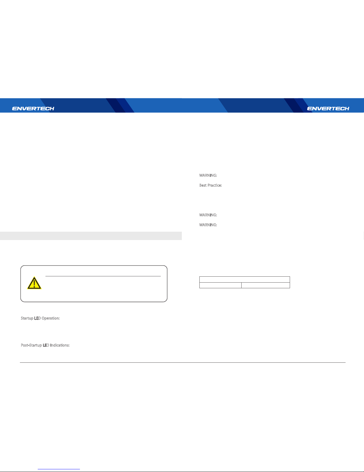
Wire size/ Inner jacket OD Max: 10AWG, 12AWG, 14AWG/ Max OD 4.65mm
Recommended sealing nut torque: 25Kgf.cm (2.5N.m)
Recommended installation temperature: 20℃ (60℉) upward
Avoid oil and gasoline
Waterproof rate :IP65
⑤Screw the sealing nut into body tightlywith a force of 25 Kgf.cm.
Please notice the symbols.
9 10
!
WARNING
!
WARNING
Only qualified personnel may connect the Envertech microinverter to
the utility grid after receiving prior approval from the electricalutility
company.
!
WARNING
Ensure that all AC and DC wiring is correct. Ensure that none of the AC
and DC wires is pinched or damaged. Ensure that all AC junction boxes
are properly closed.
!
WARNING
The microinverter is not equipped to operate in environments that
have particular flammability or explosive conditions.
!
WARNING
18mm~25mm
6.4 Cable Assembly
①Strip cable jacket 18mm~25mm.
②Disassemble the seal, the clamp
ring and the Nut, then insert through
the cable.
③Insert every wire into the holes.
④Push he cable to the end. Gently try to
pull out the cable. It should not be pulled
out.
2.5NM
Page 8
8.2 Troubleshoot an Inoperable Microinverter
Startup LED Operation:
The LED status of each microinverter blinks green to indicate normal start-up operation
approximately one minute after DC power is applied. Red blinks after DC power first
applied to the microinverter indicate a failure during the startup.
Post-Startup LED Indications:
Use a handheld mirror to view indicator lights on the undersides of the
microinverters:
Flashing Green: indicates normal operation.
Flashing Red:indicatesthat the microinverter is not operating normally. The microinverter does not sensethat the utility grid is within voltage/frequency specifications.
The microinverter cannot produce power until this is solved.
1.Turn ON circuit breaker for each microinverter AC branch circuit if there is.
2.Turn ON the main utility-grid AC circuit breaker. Your system starts producing power
after five minutes.
3.The Envertech microinverter begins communicating over the power lines to EnverBridge. The time required for all microinverters to report to EnverBridge is depent on the
number of microinverters in the system. The first units should be detected within 15
minutes but the entire system could take hours to be detected.
4.The EVT500 has the ability to auto adjust voltage and frequency according to the
settings based on local standards. If adjustments are required by your local utility, the
installer can use EnverBridge to manage the grid profile after all microinverters have
been detected.
The Envertech microinverter is powered on when sufficient DC voltage from the PV
module is applied. The LED status of each microinverter will blink green to indicate
normal start-up operation approximately one minute after DC power is applied. You
may need to use a handheld mirror to view indicator lights on the undersides of the
microinverters.
To troubleshoot an inoperable microinverter, follow the steps in the order shown
below.
WARNING:
Be aware that only qualified personnel should troubleshoot the PV array
or the Envertech microinverter.
Best Practice:
Never disconnect the DC wire connectors under load. Ensure that no
current is flowing in the DC wires prior to disconnecting. If necessary, use an opaque
covering to cover the PV module prior to disconnecting the PV module. Always
disconnect AC power before disconnecting the PV module wires from the Envertech
microinverter. The AC connector of the microinverter is suitable as a disconnecting
means.
WARNING:
The AC and DC connectors on the cabling are rated as a disconnect only
when used with an Envertech microinverter.
WARNING:
The Envertech microinverters are powered by DC power from the PV
modules. Make sure you disconnect the DC connections and reconnect DC power to
watch for the LED blinks one minute after DC is applied.
1. Make sure AC breakers is turned on.
2. Check the connection to the utility grid and verify that the utility voltage is within
allowable ranges shown in the Technical Data section.
3. Verify that AC line voltage at all solar power circuit breakers at the load center and
subpanels is within the ranges shown in the following table.
4. Verify that AC line voltage at the junction box for each AC branch circuit are within
the ranges are shown in the following table:
5. Using an Envertech disconnecting tool, disconnect the AC cable for the faulty
microinverter from the cable.
6. Verify that utility power is present in the microinverter by measuring line to line and
line to neutral at the Cable connector.
7. Visually check that the AC branch circuit connections (Cable and AC connections)
are properly seated. Reseat if necessary. Check also for damage, such as rodent
damage.
8. Make sure that any upstream AC disconnection, as well as the dedicated circuit
breakers for each AC branch circuit, are functioning properly.
Adhere to all the safety measures described throughout this manual. Qualified
personnel can use the following troubleshooting steps if the PV system does not
operate correctly.
11 12
8.Troubleshooting and Maintenance
Do not attempt to repair the Envertech microinverter.It contains no
user-serviceable parts. If the Microinverter fails, contact Envertech
customer service to obtain an RMA (return merchandise authorization)
number and start the replacement process.
!
WARNING
220/230/240 Volt AC, Single Phase
L to N
184 to 264 VAC
7.1 Energize the System
7.2 EVT500 Operation
8.1 LED Status Indications and Error Reporting
Page 9
8.3 Microinverter Maintenance
9. Disconnect and re-connect the DC PV module connectors. The LED status of each
microinverter will blink green to indicate normal start-up operation soon (less than
one minute) after DC power is applied. The LED subsequently resumes normal operation if the grid is present.
10. Attach an ammeter clamp to one conductor of the DC cables from the PV module
to measure microinverter current. This will be under one Amp if AC is disconnected.
11. Check the DC connections between the microinverter and the PV module. The
connection may need to be tightened or reseated. If the connection is worn out or
damaged, it may need replacement.
12. Verify with your utility that line frequency is within range.
Routine Maintenance, although not mandatory, is recommended to maintain
efficient operation of the PV installation.
14
It is recommended that maintenance operations shall be only
performed by qualified personnel or Envertech personnel.
The maintenance schedule may vary depending on the environmental
conditions of the installation site.
Annual Cleaning
Annual Operations
Conduct an annual visual inspection(where possible) on the
various components(DC cables, microinverters and AC cables)
to check for dust, dirt, moisture and water seepage.
Clean the equipment if necessary. Clean using compressed air,
a vacuum cleaner or special brushes, if possible.
Check that there has been no drastic change in the installa-
tion conditions that might have negative influence on the
communication between microinverters and the monitor-
ing device.
!
WARNING
13
Routine Maintenance
9.Contact
Zhejiang Envertech Corporation Ltd.
Tel : +86 579 8926 6326
Web: www.envertec.com
Email:[email protected]
Add: 24th Floor, Jintong Mansion, Center of Headquarters, Yongkang City,
Zhejiang Province, China
 Loading...