

Page 1
Zhejiang Envertech Corporation Ltd.
Tel:+86 579 8926 6326
Email:[email protected]
Add:24th Floor, Jintong Mansion,
Center of Headquarters, Yongkang City,
Zhejiang Province, China
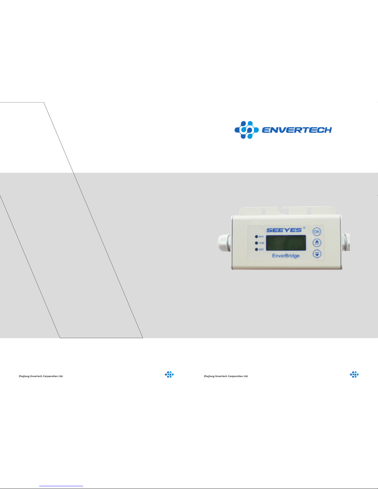
User Operating Manual
Model Number: EVB202
This manual is an integral part of the unit. Please read the instruction
manual carefully before installation, operation or maintenance. Keep
this instruction manual for future reference. This document is not to
be reproduced in any manner, nor are the contents to be disclosed
to anyone, without the express authorization of Envertech.
Page 2
Content
1. Read this First...................................................................................
2 Symbols in the Manual.....................................................................
2.1 Safety Symbols.................................................................................................
2.2 Other Symbols....................................................................................
2.3 Technical Competence........................................................................
2.4 Safety Instructions..............................................................................
3 Packing and Feature.........................................................................
3.1 Structure of EVB201...........................................................................
3.2 Main Functions....................................................................................
3.3 Technical Parameters..........................................................................
4 Installation.........................................................................................
4.1 Operating Condition............................................................................
4.2 System Diagram..................................................................................
5 Operating Static................................................................................
5.1 Working Mode.....................................................................................
5.2 Grid Connection..................................................................................
5.4 Installation Checklist...........................................................................
5.5 Start- Up Checks................................................................................
6 EVB202 LCD......................................................................................
6.1 Brief Introduction.................................................................................
6.1.1 Description of LCD..............................................................................
6.2 LCD Interface......................................................................................
6.2.1 Start-up Interface................................................................................
6.3 Selection Interface............................................................................
6.4 Explanation of Malfunction.............................................
6.5 Application..............................................................................
7 Disconnecting an EVB202 from the System...........................
8 Monitoring and Troubleshooting and Maintenance.......................
8.1 Safety Checks.....................................................................................
8.2 Maintain Periodically............................................................................
8.3 Internet WEB.......................................................................................
9 Contact...............................................................................................
1
1
1
2
3
4
6
6
6
7
7
7
7
9
10
10
11
12
12
12
12
12
12
13
17
17
17
18
18
18
19
21
Page 3
Thank you for selecting Envertech– a leading supplier of microinverter products for
the solar PV market. Envertech’s new product “EVB202” acts as the power interface
(PI) to the utility grid. It is an information gateway for the Envertech microinverter. The
data of real-time performance of energy harvest for all Envertech microinverter
systems can be collected by EVB202, and transmitted to Envertech Monitoring
Platform called EnverPortal to achieve a global data monitoring for PV power plants.
The user manual includes EVB202 overview, installation, operation instruction and
technical parameters. To assure properly installation and operation, please carefully
read this user manual before installation, and pay attention to the caution symbol
affixed on the product.
Please hand the user manual to the end users.
2 Symbols in the Manual
2.2 Other Symbols
!
DANGER
1 2
1 Read this First
2.1 Safety Symbols
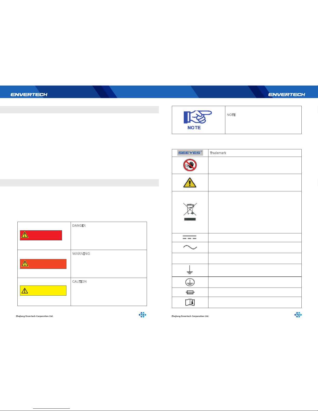
Warnings and cautions tell you about the dangerous conditions that can occur if you
do not follow all instructions in this manual.
Please read following safety symbols that indicate dangerous conditions and important
safety instructions.
DANGER
The DANGER symbols in this manual and on
the EVB202 indicate a hazard with a high level
of risk which if not avoided, will result in death
or serious injury.
CAUTION
The CAUTION symbols in this manual and on
the EVB202 indicate a hazard with a low level of
risk which if not avoided, could result in minor
or moderate injury.
NOTE
The NOTE symbols in this manual indicate the
important product information.
!
CAUTION
Some Symbols replace words on the equipment, on a display, or in manuals.
Trademark
No access for unauthorized personal
Caution, risk of danger
Symbol for the marking of electrical and electronics devices
according to Directive 2002/96/EC indicates that the device
accessories and the packaging must not be disposed as
unsorted municipal waste and must be collected separately
at the end of the usage. Please follow Local Ordinances or
Regulations for Disposal or contact an authorized representative of the manufacturer for information concerning the
decommissioning of equipment.
Direct curren
Alternating current
PE
Protective conductor
Earth(ground) terminal
Protective conductor terminal
Fuse
Refer to the operating instructions
!
WARNING
WARNING
The WARNING symbols in this manual and on
the EVB202 indicate ahazard with a medium
level of risk which if not avoided, could result
in death or serious injury.
Page 4
should ever be undertaken or attempted by anyone not having such qualifications.
Compliance with safety regulations depends upon installing and configuring system
correctly, including using the specified wiring. Only professional assemblers who are
familiar with requirements for safety, photovoltaic system and EMC must install the
system. The assembler is responsible for ensuring that the end system complies with
all the relevant laws in the country where it is to be used. Envertech requires using
only genuine replacement parts, manufactured or sold by Envertech for all repair parts
replacements.
Read completely through each step in every procedure before starting; any exception
may result in a failure to properly and safely complete the attempted procedure.
This chapter contains the safety instructions that you must follow when installing,
operating and servicing the unit. If ignored, physical injury or death may follow, or
damage may occur to the unit. Read the safety instructions before you commence
work on the unit. If you are unable to understand the Dangers, Warnings, Cautions or
Instructions, contact the manufacturer or an authorized service dealer before installing, operating and servicing the unit.
To ensure your personal safety and the proper use of EVB202, please carefully read
this manual before installation. If the product is damaged during installation without
complying with this manual, Envertech will not be responsible for any quality assurance and other risks.
For Envertech EVB202 Warranty Terms and Conditions, see the appendix of this manual.
• Be aware that only qualified personnel should install and /or replace Envertech EVB202.
• Perform all electrical installations in accordance with all local electrical codes.
• Comply the rules of correctly use of tools and personal protective equipment (PPE) for
insuring the EVB202 safe running.
• Be aware that only qualified personnel should maintain Envertech EVB202.
• Connection of any photovoltaic system to the electrical utility grid should only commence
after receiving prior approval from the utility company.
3 4
PV
PCS
+
_
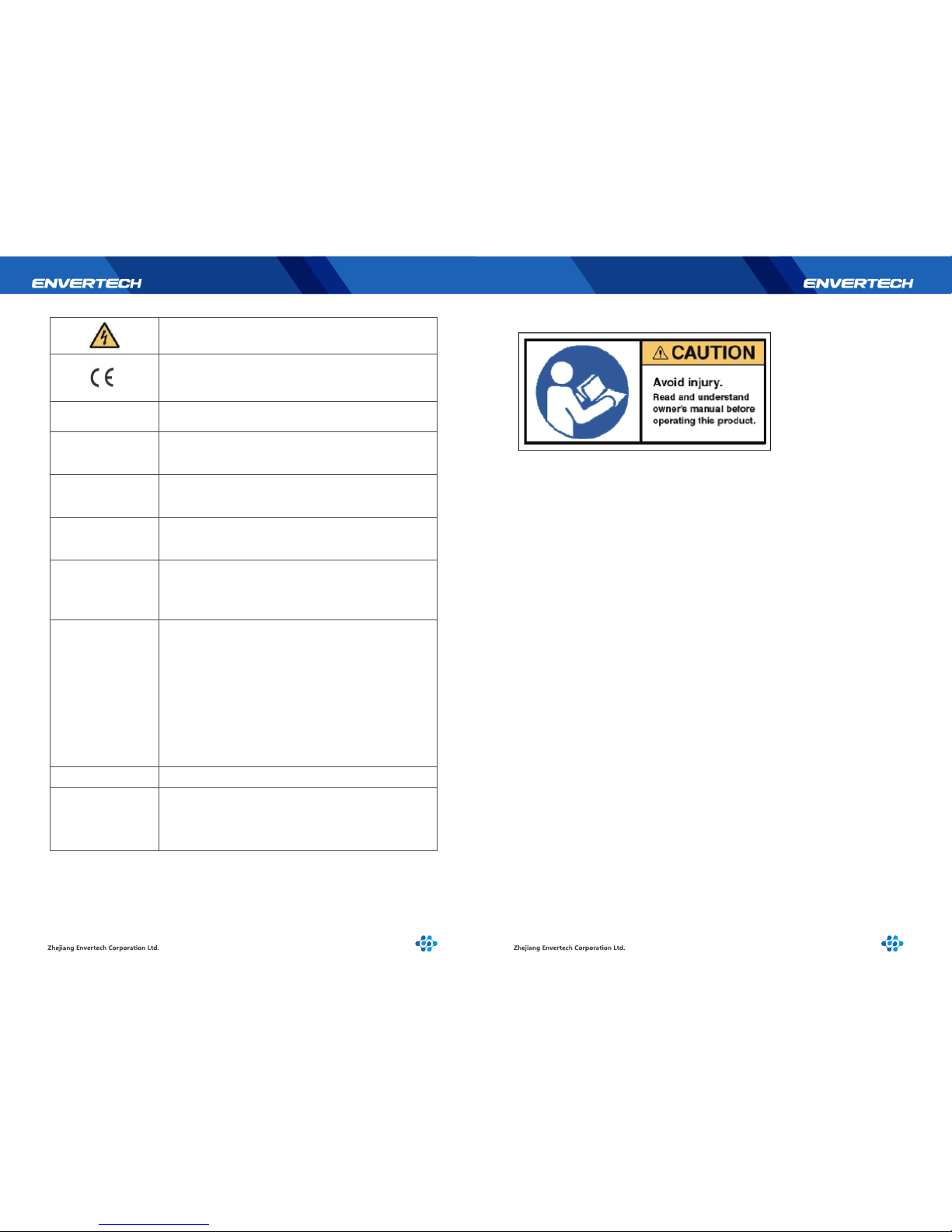
Caution, risk of electric shock
CE mark is attached to the solar EVB202 to verify that
the unit follows the provisions of the European Low
Voltage and EMC Directives.
Photovoltaic
DC terminal, indicating the polarity of the connections,
positive, all positive connections shall be made with
red insulated wires.
DC terminal, indicating the polarity of the connections,
negative, all negative connections with black insulated
wires.
Power conversion equipment, hereby is our DC/AC inverter.
SERVICE PERSONNEL
A person having appropriate technical training and
experience necessary to be aware of hazards to which that
person may be exposed in performing a task and of
measures to minimize risks to that person or other persons.
Qualified personnel
Person adequately advised or supervised by an electrically
skilled person to enable him or her to perceive risks and
to avoid hazards which electricity can create. For the purpose
of the safety information of this manual, a "qualified person"
is someone who is familiar with requirements for safety,
refrigeration system and EMC and is authorized to energize
ground, and tag equipment, systems, and circuits in accordance with established safety procedures. The EVB202 and
endues system may only be commissioned and operated
by qualified personnel.
DVC Decisive voltage class
Closed Electrical
Operating Area
Room or location for electrical equipment to which access is
restricted to skilled or instructed persons by the opening of
a door or the removal of a barrier by the use of a key or tool
and which is clearly marked by appropriate warning signs.
2.3 Technical Competence
The procedures described in this manual should be performed by trained and authorized personnel only. Maintenance should only be undertaken by competent individuals
who have a general knowledge and experience with devices of this nature. No repairs
2.4 Safety Instructions
Page 5
3 Packing and Feature
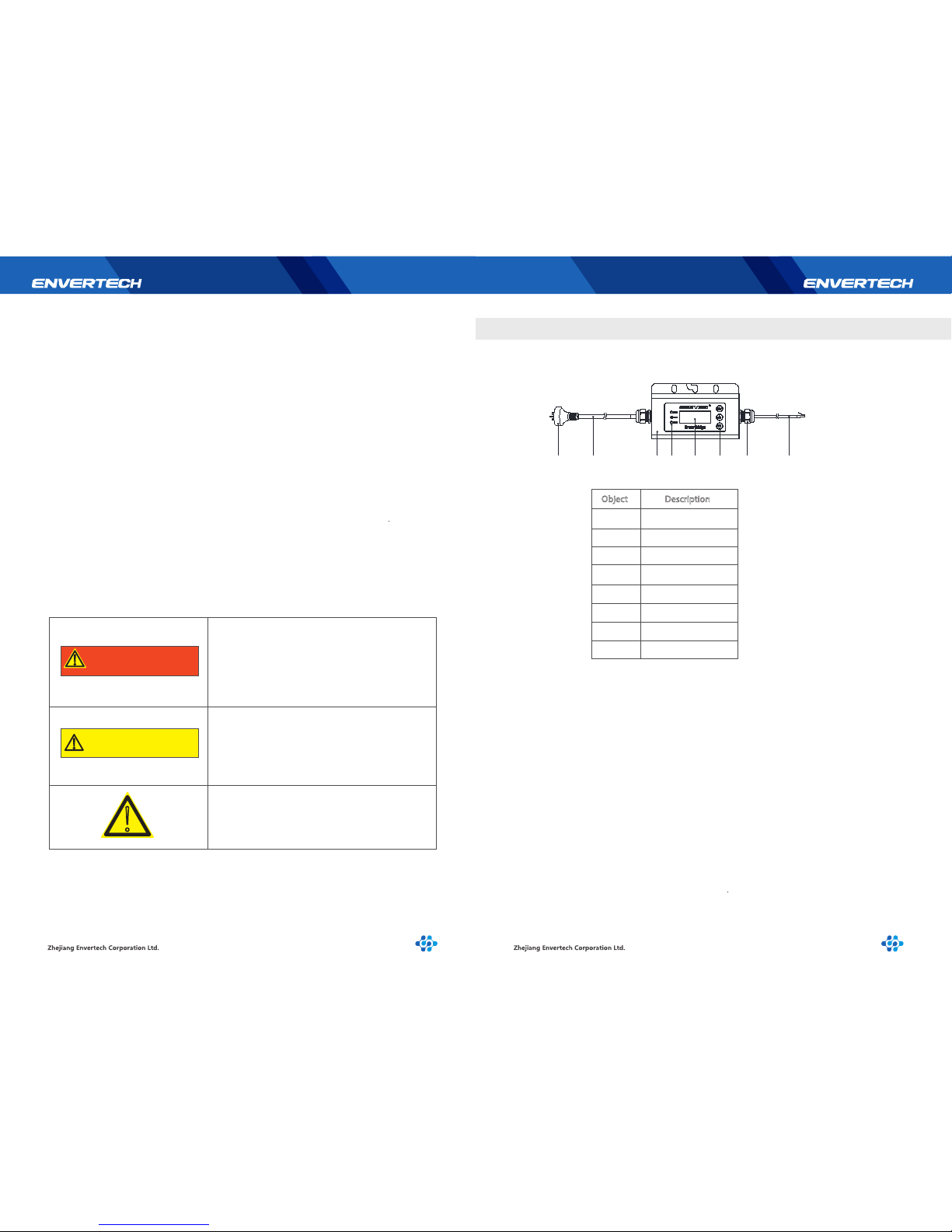
3.1 Structure of EVB202
3.2 Main Functions
5 6
!
WARNING
WARNING:
Be aware that the input AC voltage of the
Envertech EVB202 shall not exceed the
rated voltage; higher voltage may cause
permanent damage to the device. It contains no user serviceable parts.
CAUTION:
SAVE THESE INSTRUCTIONS– This manual
contains important instructions for EVB202
that shall be followed during installation
and maintenance.
!
!
CAUTION
The EVB202 MUST be installed and debugged complying with this manual by the
professional authorized by Envertech.
• All electrical installation MUST meet the local standard.
• To assure the safe running, must comply with the relative standard for using the tool
properly and Personal Protective Equipment (PPE). Away from the chemical and reagent.
• The EVB202 must be installed in environments suitable for its IP rating.
• CAUTION! The device is intended for fixed installation, located on a part that is not
removable without impairing the operation of the unit.
Servicing is limited to qualified service personnel.
• WARNINGS - The printed circuit boards contain components sensitive to electrostatic
discharge. Wear a grounding wrist band when handling the boards. Do not touch the
boards unnecessarily.
• WARNINGS - Do not operate any device which is damaged, lacking parts or dented.
Failure to observe this warning may result in an electric shock, injury, fire or accident.
• WARNINGS - Before installing the unit, agree with the customer on the site.
• WARNINGS - The output connection with AC grid shall be protected by a max. 20A
circuit breaker.
• The EVB202 shall be connected with the Envertech EVT248 or EVT500 inverter as a
system. It cannot operate as a stand-alone unit or in case of AC grid disruption.
Warning:
Only authorized persons can be allowed
for installation of inverters.
Object
Description
1
2
3
4
5
6
7
8
Network Cable
Gland Connector
Touch Key
LCD Screen
LED
Casing
AC Cable
Plug
Use the Power Line Carrier Communication (PLCC) technology within photovoltaic
power plant
By PLCC technology, EVB202 collects power generation data from the PV power plant,
and transmits to the EnverPortal database.
2 1345678
Page 6
4 Installation
3.3 Technical Parameters
Model
Interface
Power Line Communication
LCD
Ethernet
Capacity
Numbers of devices connected
Power Requirements
AC Supply
Power Comsumption
Dimensions
Weight
Ambient Temperature Range
Enclosure Environment Rating
Features
Compliance
Warranty
Mechanical Data
Cooling
EVB202
Envertech Proprietary
LCD Screen
RJ45
Monitor up to 40 units of panels
220V/230V/240V;50Hz/60Hz
225mm*50mm*107mm
3W
740g
Natural convection- no fans
-40℃~65℃
IP65
CE
5 Years
7 8
4.1 Operating Condition
Operating Ambient Temperature: -40℃~65℃
Operating Relative Air Humidity: <=90%
Rated Input AC: 230V/50Hz
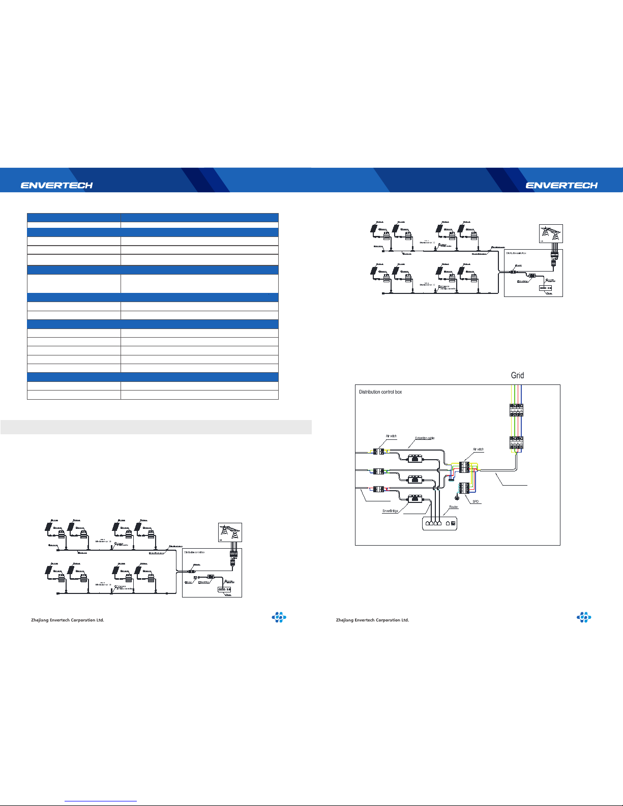
4.2 System Diagram
Single phase system
Option 1:
Option 2:
Three-phase system
Extention cable
Extention cable
Network cable
6
1
2 2
1
1 1
2 2
5
1
2 2
1
1 1
2 2
9
10
6
7
11
12
6
1
2 2
1 1 1
2 2
5
1
2 2
1
1 1
2 2
9
10
11
7
6
Page 7
9 10
WARNING
Connect the EVB202 to the electrical utility grid
only after receiving prior approval from the utility
company.
WARNING
Only qualified personnel could connect Envertech
EVB202 to the electrical utility grid.
5 Operating Static
Monitoring Device EVB202 is a core product developed by Envertech. It realizes the
connection between the solar power plant and the internet. As an intelligent communication gateway, EVB202 uses Envertech’s Power Line Communication (PLC)
technology to continuously monitor the data of energy harvest of solar power plant
such as power, voltage, current and frequency. It can also transmit the real-time data
of energy harvest to EnverPortal to realize the monitoring around the world.
The minimum functionality of the EVB202 module is to achieve the connection
between the PV power plant and internet. RJ45 cable should be simultaneously matched
with EVB202 module.
The working modes of an Envertech EVB202 are:
Start up
Active
Fault
Standby
5.1 Working Mode
5.2 Grid Connection
The detailed working mode descriptions are as below:
Start up
Start up mode is for a newly installed EVB202. This start-up mode must base on proper
AC microinverter andEthernet cable’s connection.
Active
When the EVB201 is in normal operation process, this ensures that the power available
from microinverter array is exported to the utility grid.
Fault
If the system does not operate correctly, Envertech EVB202 will stop automatically
and enter into disabled mode. The Envertech EVB202 system keeps detecting the
disabled information, and it will be in disabled mode until faults release. If the
inoperative EVB202 has been repaired and matched to the electrical utility grid, the
whole system would enter operation mode after 60 seconds to 5 minutes. Be aware
that only qualified personnel should maintain Enveretch microinverters.
Standby
When the EVB201 is in operation process but keeps with low voltage and current
from microinverter side for a certain time. The EVB202 manages transition from
“Active” to “Standby”. In “Standby” mode, microinverters keep detecting the
energy output of each microinverter. When the output energyreaches the power
generation conditions, the inverter would enter into “Active” from the “Standby”
state.
• The equipment maintenance only can be carried through by
service department of Envertech, or the service centre or the
professional authorized by Envertech. Maintenance personnel
should be familiar with all the warnings in this manual and the
proposed steps.
• Must be sure to disconnect the input and output power before
removal of equipment for maintenance.
EVB202 system connects to grid automatically. It detects and monitors the performance of
each PV module through each microinverter. When the output energy reaches the power
generation conditions, the EVB202 system begins to collect the data from microinverters.
To ensure the safe operation of the devices, they may be installed and commissioned only
by qualified personnel in full compliance with the warnings referred to in this manual.
Checklist
Check the mechanical and electrical installation of the unit before start-up. Go through the
checklist below together with another person. Read the safety instructions and EC directives
on the previous pages of this manual before you work on the unit.
Mechanical Installation
Check screw connections on the EVB202 for tightness. The ambient operating conditions
are considered. (See technical parameter.) The unit is fixed properly on a nonflammable
wall or the combiner box or the rack. (See Mechanical installation.) The cooling air will flow
freely. The unit is fixed tightly and support is enough. (See Mechanical installation.)
5.3 Installation Checklist
!
!
Page 8
6 EVB202 LCD
11 12
Electrical Installation
Check all screws of the connection terminals in the installation system before and after the
EVB202 for tightness.
The AC input voltage matches the unit nominal voltage. Assure EVB202 AC cable’s connection
and its tightening torques are OK. There is no tool, foreign object or dust from drilling inside
the unit. Unit, connection box and other covers are in place. The Ethernet cable’s connection
is OK. The external cords and cables are fixed tightly, and strain relief clamp is provided for
external accessible cords and cables. Cord and cable inlets are sealed completely after
cord/cable installation.
The device has been checked at the factory and adjusted so that it can be commissioned
immediately after being installed.
Following Section Installation checklist, for your personal safety and to avoid damage, the
following safety checks should be performed before a qualified person who has adequate
training, knowledge, and practical experience performs these tests. The data should be
recorded in an equipment log. If the device is not operated properly or fails any test, the
device has to be repaired.
1. Inspect the equipment and accessories for mechanical and functional damage.
2. Inspect the safety relevant labels for legibility.
3. Inspect the fuse to verify compliance with rated current and breaking characteristics.
4. Measurement of insulation resistance
5. Measurement of earth resistance
6. Mounting structures: Verify tightness and integrity of bolts and other fastening devices
and also check if there is significant corrosion.
5.4 Start-up Checks
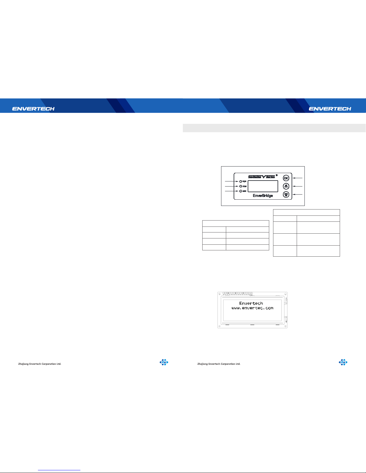
The purpose of the manual for LCD of EVB202 is to help users to know the functions
quickly and use LCD to understand the performance.
Number
1
2
3
Description
OK/Exit
Up/Add
Down/Reduce
Button
6.1 Brief Introduction
6.1.1 Description of LCD
Number
Description
The green light indicates
normal operation
The yellow light indicates
communicating
The red light indicates
malfunction
LED
4
5
6
6.2.1 Start-up Interface
The start-up signal shows up on the LCD screen once EVB202 equipment is powered
on and starts to work. The first line shows the company name Envertech and the second
line shows the company website www.envertec.com (as shown below).
6.2 LCD Interface
1
2
3
4
5
6
Page 9
13 14
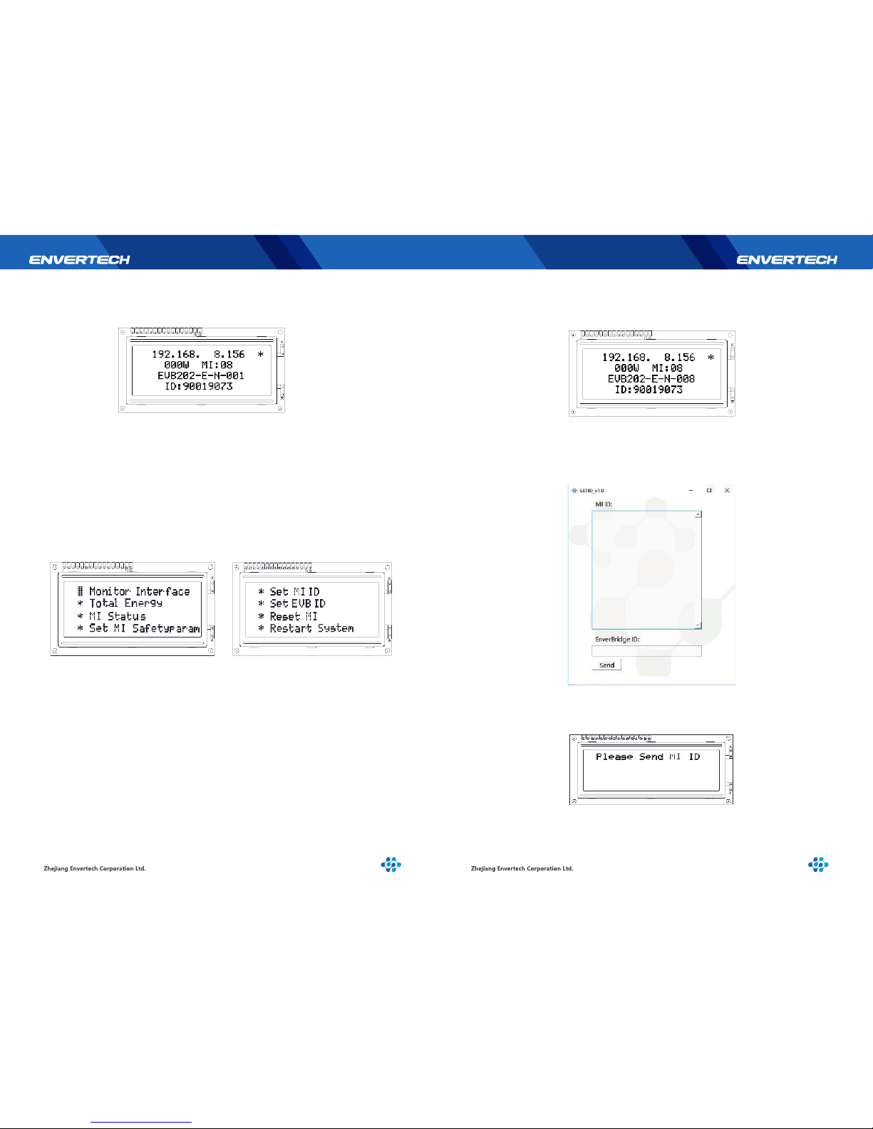
The second interface will be shown as below.
Press “OK” button to enter [menu interface] which is shown as below.
*Monitor Interface
*Total Energy
*MI Status
*Set MI safetyParam
*Set MI ID
*Reset MI
*Restart System
Fist line:
Second line:
Third line:
Fourth line:
IP address( 192.168.0.255 means network connection fails, if the IP
address with star﹡behind indicates right network connection .)
Real-time total MI power , Total number of connected MI(Only after you
finish Step 1 in 6.3 selection interface )
EVB program version
EVB ID number
The description is as the followings.
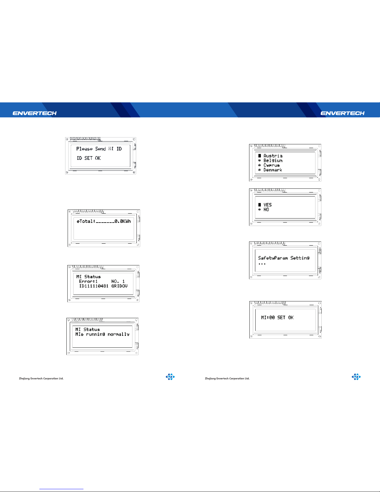
Step 1.
Step 2.
The first priority thing you should do is to [Set MI ID] , please make sure
your EVB202 is connected to the same router as your computer is connected.
Use the scanner or manually input to enter into the EVB202 ID and the
inverter ID to the software as below.
Press“Monitor interface” ,back to main interface, background light
will be on , and be off after 30 sec.
6.3 Selection Interface
Please press[Set MI ID] ,you will see the content shown as below
Page 10
15 16
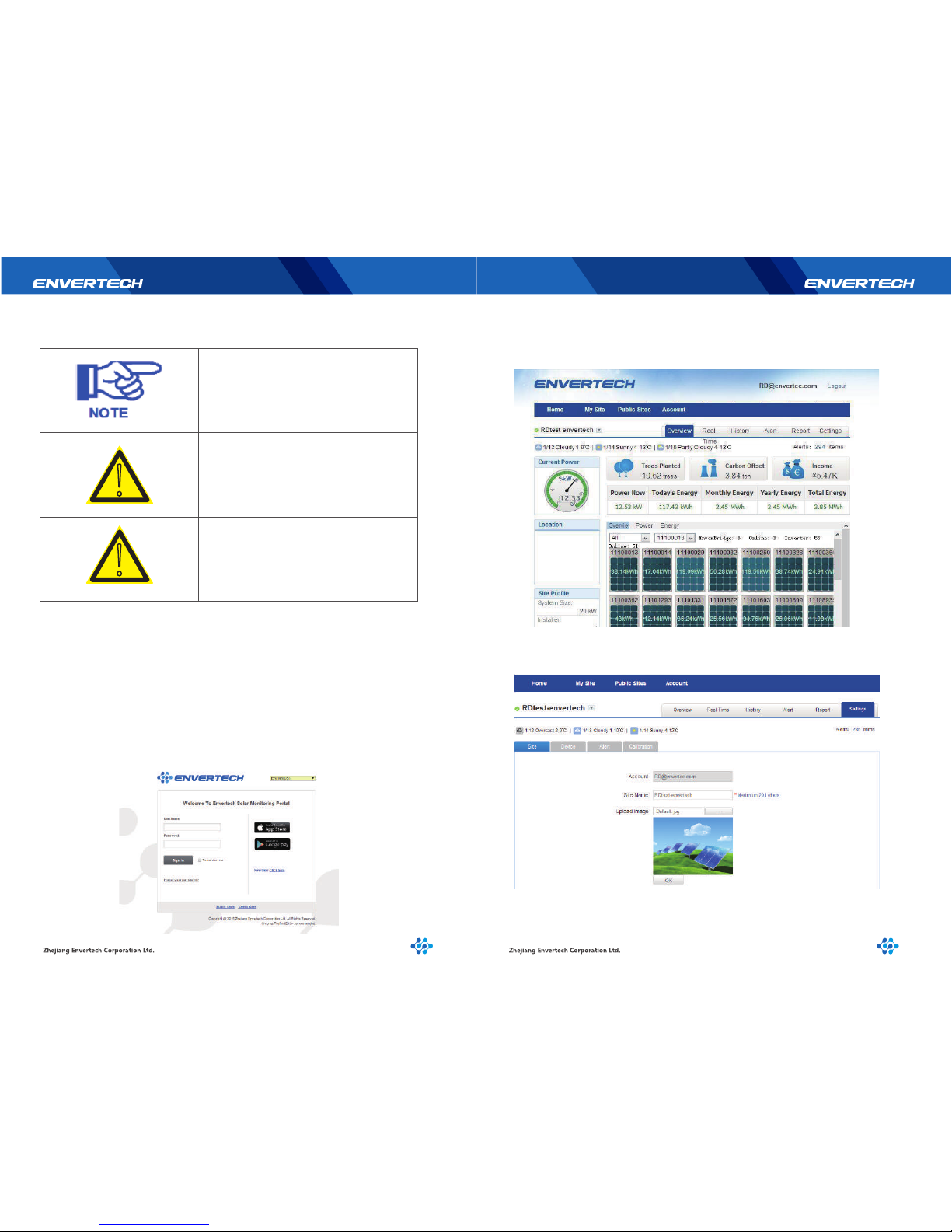
Step 3.
Press [Total Energy] to check Total Energy, and press “ok”back to the main
interface.Press [Total Energy] to check Total Energy, and press “ok”back to
the main interface.
Step 5.
Press “Set MI SafetyParam” to set your local SafetyParam. Choose the
country through “Up” and “down” buttons.
Choose “yes” to finish your setting, which would take 1-2 minutes.
MI:XX means the total number of MI you have successfully set.
Press “ok” back to the main interface.
Step 4.
Press [MI Status] , the interface shows as below, press“ok”back to main interface.
This interface indicates there is 1 error totally , “NO.1” means the first error.
This means working normally.
Then you can press “send” button in the software to complete the setting
Meanwhile, “ID Set ok” will be also shown on the EVB202 screen.
Then EVB202 will restart within 3 seconds.
Page 11
19 20
NOTE
Disabled EVB202 does not affect the operation
of all Envertech microinverter system.
WARNING
Never disconnect the DC wire connectors under
load. Ensure that no current is flowing in the DC
wires prior to disconnecting and the AC breaker
is turned off.
WARNING
Be aware that only qualified personnel should
troubleshoot the PV array or the Envertech
microinverter.
Introduction
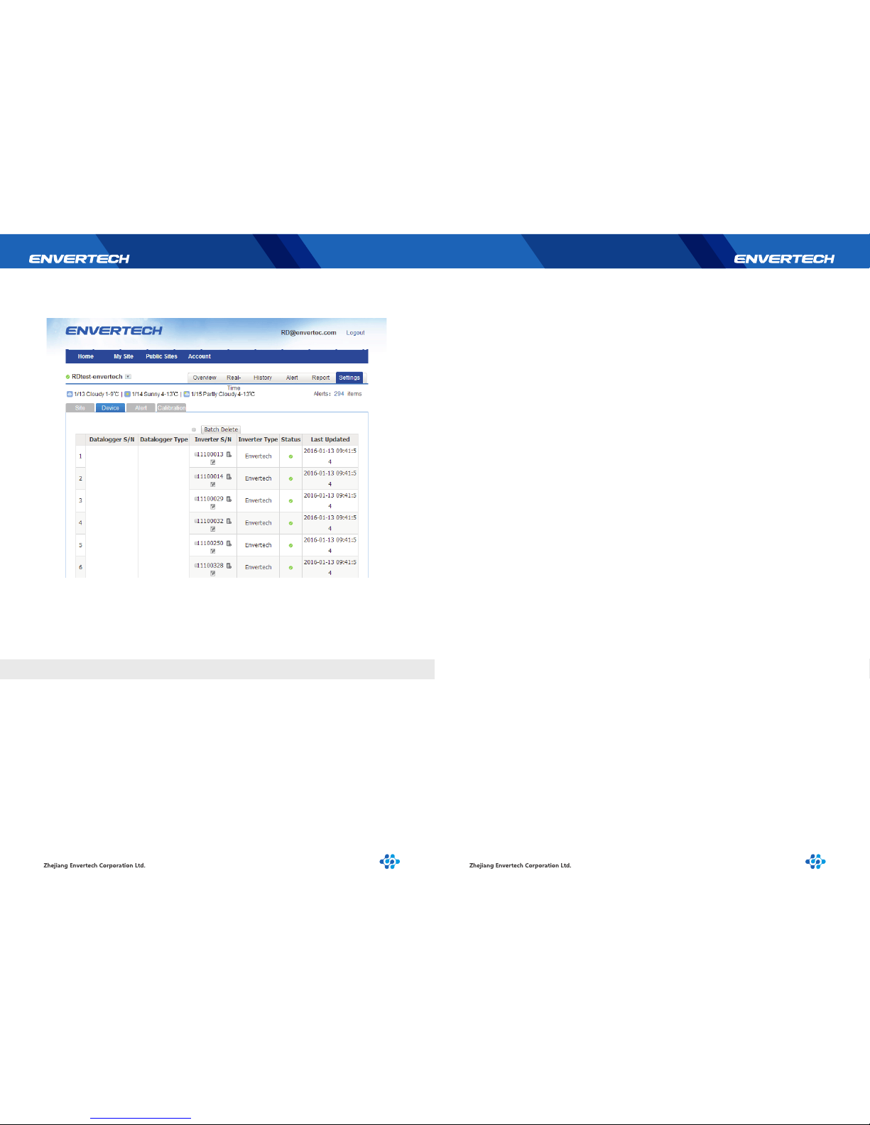
Use the monitoring website EnverPortal developed by Envertech to monitor the
statistics information of the energy harvest for all Envertech microinverter system and
monitor per-module’s performance which is integrated into the Envertech
microinverter system.
Register address:http://www.envertecportal.com/
Account Registration
Register successfully and enter into the page below:
Click“Settings”and enter into the page below:
8.3 Internet WEB
!
!
Page 12
21 22
Zhejiang Envertech Corporation Ltd.
Add: 24th Floor,Jintong Mansion,Center of Headquarters,
YongKang City,Zhejiang Province,China
Tel: 0086-0579 89266326
Web: www.envertec.com
Click “Device”.
At the last part of the page, click “Add”, and fill the EVB202 serial number in the
blank space, for example:“90000001”. Click “OK” and finish the registration.
9 Contact
Page 13
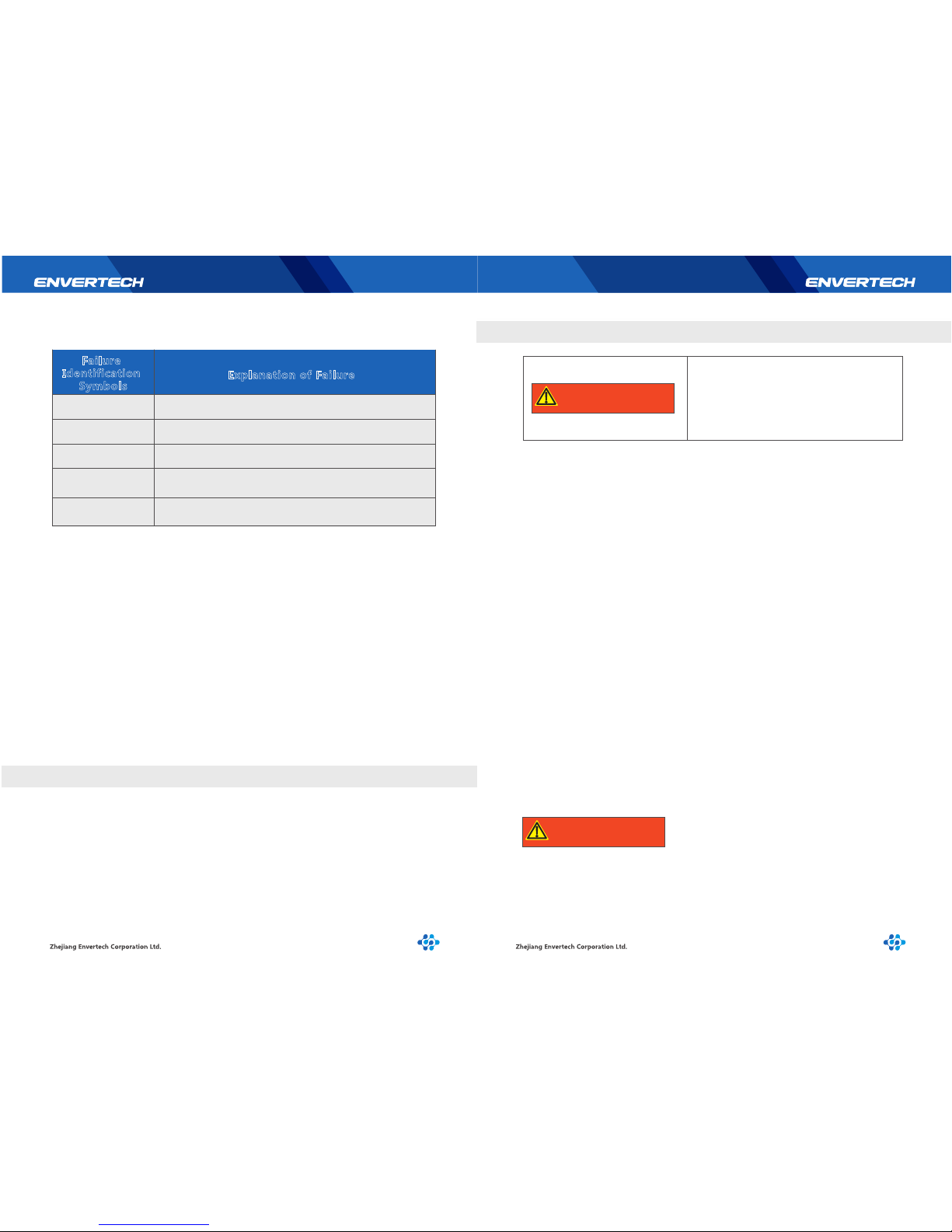
Failure
Identification
Symbols
Explanation of Failure
GRIDOV
GRIDUV
GRIDOF
GRIDUF
GRIDSU
Over Voltage
Under Voltage
Over Frequency
Under Frequency
Voltage Fluctuation
6.4 Explanation of Malfunction
17 18
The monitoring status can be seen by users through LCD screen.
The installation is completed once the monitoring interface shows up on LCD screen.
According to what is shown on the LCD screen, the maintenance personnel can see where
the problem comes from.
1. If the LCD screen stays at the interface of unlocking and constructing network,it means
the networking fails. Then MIs should be checked to make sure they are connected
properly and producing power.
2. If it shows on LCD screen for a long time that the number of MIs is less than that of
MIs in reality, it’s suggested to check whether there are any failed MIs.(To find out
which one is not working, please get information from EnverPortal.)
3. According to malfunction explanation, maintenance personnel can locate the problems
and make maintenance easier.
Only trained and authorized professional personnel WHO ARE FAMILIAR WITH
THE REQUIREMENTS OF SAFETY is allowed to perform service and maintenance
work.
No user-serviceable parts inside. If the EVB202
has any malfunction, send it to the authorized
representative or manufacturer. Never open and
try to repair it by yourself.
Safety checks should be performed at least every 12 months by manufacturer’s
qualified person who has adequate training, knowledge, and practical experience to
perform these checks. The data should be recorded in an equipment log. If the device
is not functioned properly or fails any of tests, the device has to be repaired.
For safety check details, refer to this manual, section 3 Safety Instruction and EC
Directives.
To ensure safe disconnection of the EVB202 from the solar power plant, it must NOT be
carried out under load conditions. Ensure the following disconnection steps are carried
out in the order shown:
1. Disconnect the AC by isolating the branch via the circuit breaker.
Or Disconnect the plug from the wall socket.
2. Disconnect the Ethernet cable.
3. Remove the EVB202 from the system.
6.5 Application
8.1 Safety Checks
Only qualified person can carry out the following work.
During the process of using the EVB202, the person responsible shall examine and
maintain the machine regularly. The concrete operations are as follows.
1. Check the EnverPortal website to confirm if the screen of the EVB202 is normal or
not. This check should be performed at least every 6 months.
2. Check if the cables are damaged or aged. This check should be performed at least
every 6 months.
3. Check for dust or debris. If there’s dust and or debris on EVB202, clean it lightly
by brush or vacuum the unit to remove dust particles, which may cause compon ents inside overheat.
Before cleaning the EVB202:
Wear gloves and safety glasses.
Disconnect the EVB202 from the Grid – Isolating device.
Clean the EVB202 with wet cloth carefully.
8.2 Maintain Periodically
7 Disconnecting an EVB202 from the System
8 Monitoring and Troubleshooting and Maintenance
!
WARNING
!
WARNING
Page 14

 Loading...