

Page 1
Zhejiang Envertech Corporation Ltd.
Tel:+86 579 8926 6326
Email:[email protected]
Add:24th Floor, Jintong Mansion,
Center of Headquarters, Yongkang City,
Zhejiang Province, China
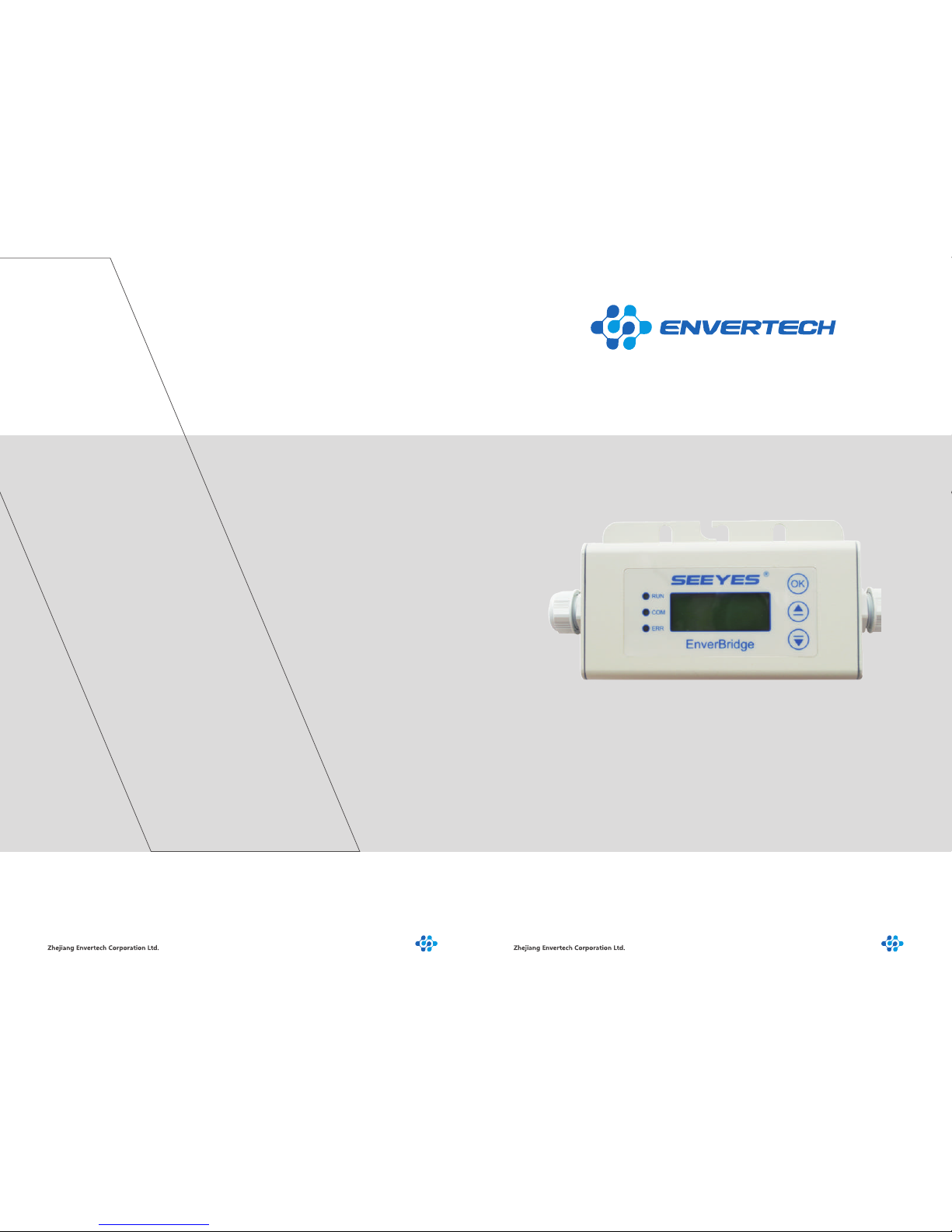
User Operating Manual
Model Number: EVB202
Zhejiang Envertech Corporation Ltd.
All rights reserved
Page 2
Content
1. Overview............................................................................................
1.1 Brief Introduction..............................................................................................
1.2 Features.............................................................................................................
1.3 Key Equipments...............................................................................................
2 Installation Guide.............................................................................
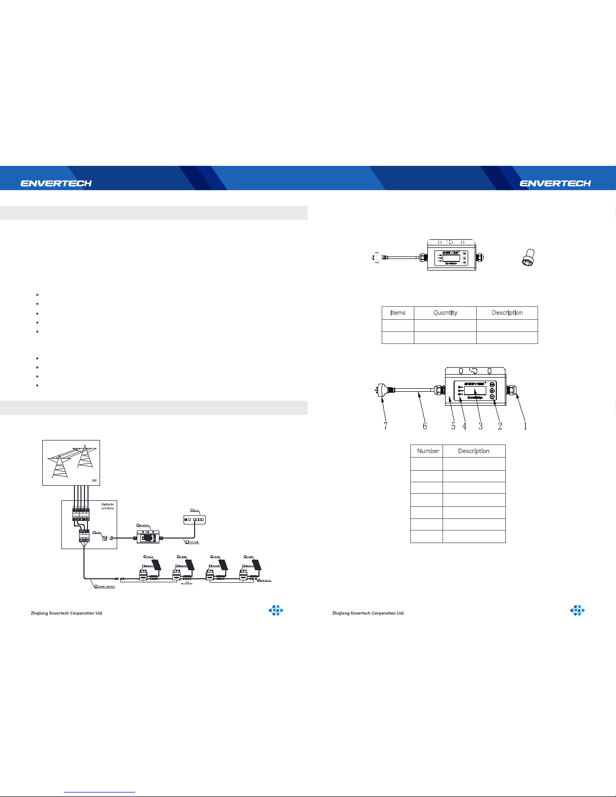
2.1 System Diagram..............................................................................................
2.2 Parts and Features..........................................................................................
2.2.1 Parts....................................................................................................................
2.2.2 Structure of EVB202.......................................................................................
2.2.3 Installation Steps..............................................................................................
2.2.4 Main Functions.................................................................................................
2.2.5 Technical Parameters.....................................................................................
2.3 Register a new account......................................................................
2.4 Add devices..........................................................................................
2.5 Monitoring Webportal Interface....................................................................
2.5.1 Overview Page................................................................................................
2.5.2 Real-time Monitoring.......................................................................................
2.5.3 Historical Data..................................................................................................
3 Begin to use......................................................................................
3.1 LCD of EVB202....................................................................................
3.1.1 Description of LCD..........................................................................................
3.1.2 Start-up Interface.............................................................................................
3.1.3 Selection Interface...........................................................................................
3.1.4 Explanation of Malfunction............................................................................
3.2 MI Quick Binding.................................................................................
4 Basic Operations..............................................................................
4.1 Safety Checks......................................................................................
4.2 Maintain Periodically..........................................................................
4.3 Common Problems..........................................................................................
5 About us............................................................................................
1
1
1
1
1
1
2
2
2
3
4
4
4
5
6
6
6
6
7
7
7
7
8
12
13
15
15
15
15
16
Page 3
2.2 Parts and Features
1 2
1 Overview
2 Installation Guide
1.1 Brief Introduction
1.2 Features
2.2.1 Parts
2.2.2 Structure of EVB202
The monitoring device EVB202 is the commnication interface of microinverters, which
can effectively communicate with any Envertech microinverter and transmit the latest
information of the microinverter to the server. Users can have access to data through
a simple,flexible and convenient way.
5 Years Warranty
Power Line Communication
Simple Installation and Operation
IP65 Protection Rating(Indoor&Outdoor)
Real-time Monitoring through Website & App
Microinverter
Monitoring Device EVB202
Smart Monitoring Webportal- EnverPortal
Smart Monitoring Application- EnverView
1.3 Key Equipments
2.1 System Diagram
1
2
1
2
1
2
1
2
length 746 mm
length 1050 mm
length 1050 mm length 304 mm
8
7
6
4
9
3
A B
Number Description
1
2
3
4
5
6
7
Gland Connector
Touch Key
LCD Screen
LED
Casing
AC Cable
Plug
Items Quantity Description
A
B
1
1
Monitoring Device
Screw
Page 4
3 4
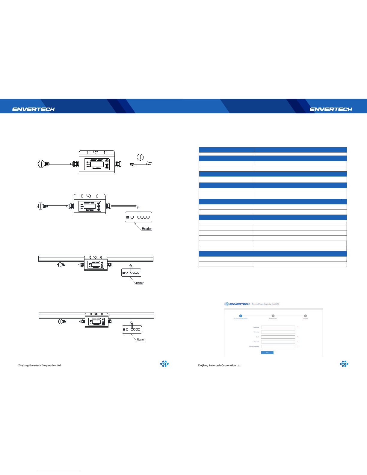
2.2.3 Installation Steps
Step 1:
Use the screwdriver to open the right side of the cover plate. Run the RJ45 cable
through the connector and plug into the network port. Put back the cover plate and
check if it’s sealed completely.
2.2.4 Main Functions
2.2.5 Technical Parameters
By the Power Line Carrier Communication (PLCC) technology, EVB202 collects power
generation data from the microinverter, and transmits to the EnverPortal database.
Step 2:
Lay the RJ45 cable and connect the other end of the cable to the router;
Step 3:
Place the mounting hole of EVB202 frame onto the mounting system.
Step 4 :
Insert the M8 screw into the mounting hole with a hexagon screwdriver.
Model
Communication
Power Line Communication
Ethernet
LCD
Capacity
Interface
Numbers of devices connected
AC Datas
AC Supply
Power Comsumption
Dimensions
Weight
Ambient Humidity
Ambient Temperature Range
Enclosure Environment Rating
Certification and Warranty
Compliance
Warranty
Mechanical Data
Cooling
EVB202
PLCC
TCP/IP Protocol
4×20 Bits
Monitor up to 40 units of panels
220V/230V/240V; 50Hz/60Hz
225mm*50mm*107mm
≤3W
740g
Natural convection- no fans
≤90%
-40℃~+65℃
IP65
CE
5 Years
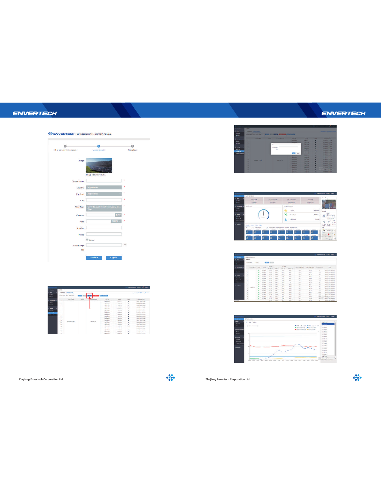
2.3 Register a new account
EnverPortal, an intelligent monitoring system developed by Envertech, monitors the
performance of the whole Envertech microinverter system as well as that of every
module in the system. New users need to register an account.
Registration address: www.envertecportal.com
Page 5
5 6
Click “Next”, and create a power station
2.4 Add devices
Select “Settings”→ “System Info”→ “Device Manager”,and click “Add”to
enter the interface.
2.5 Monitoring Webportal Interface
2.5.1 Overview Page
Smart Monitoring Webportal——EnverPortal,for single power station
2.5.2 Real-time Monitoring
Click “Realtime” button to enter the realtime data page.
2.5.3 Historical Data
Click “History” to enter the data graphs page
Enter the correct SN of EnverBridgein the popup box and click “OK”.
Page 6
3 Begin to use
7 8
3.1 LCD of EVB202
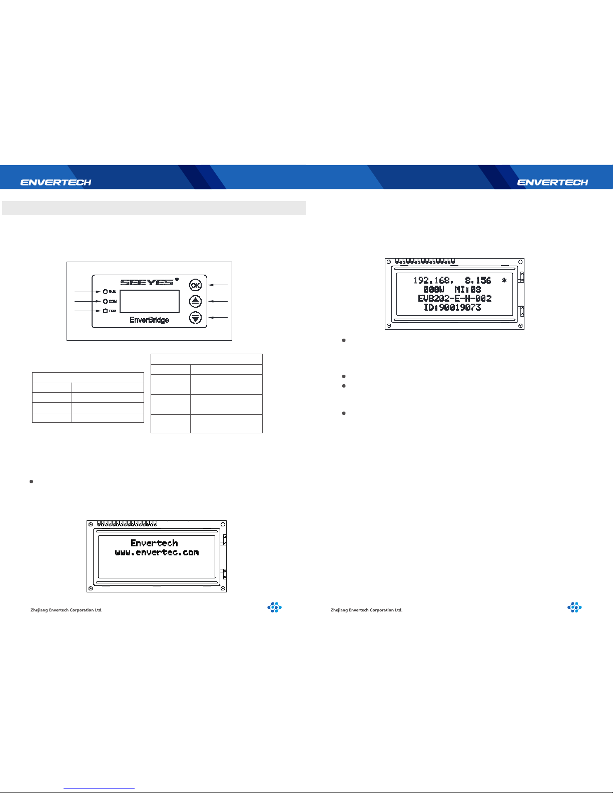
The LCD displays the device’s operation satusand realtime system data. It helps users
to check the system status timely and conveniently.
When EVB202 displays the Start-up interface, the first line shows the company
name “Envertech” and the second line shows the company website
“www.envertec.com”.
Start-up time: 30s,as shown below:
3.1.2 Start-up Interface
After EVB202 is started, it will enter normal working status. At this moment the
LCD will display the monitoring information.
First line: IP address;
Second line: Power & quantity of microinverters
Third line: EVB version;
Fourth line: EVB ID number (as shown below):
IP address will be shown on the first line of the screen, for example:
192.168.9.150. If the first line shows 192.168.0.255, it means there is no
connection with the server. A‘*’stands for successful connection with the
server, and no‘*’stands for no connection.
Real-time power, is displayed at the beginning of the second line.
The quantity of microinverter is displayed at the end of the second line, which
means how many MIs have successfully transmitted data. On the third line it
shows the software version: EVB202-E-N-002.
On the fourth line it shows the EnverBridge ID: each EnverBridge owns only
one ID. For example, this EnverBridge’s ID is 90019073.
In the newly installed monitoring system, you firstly need to set the microinverter ID
on the EVB202. It is recommended to set the microinverter ID before installing it into
the power station. For details, please see the following sector 3.1.3..
3.1.3 Selection Interface
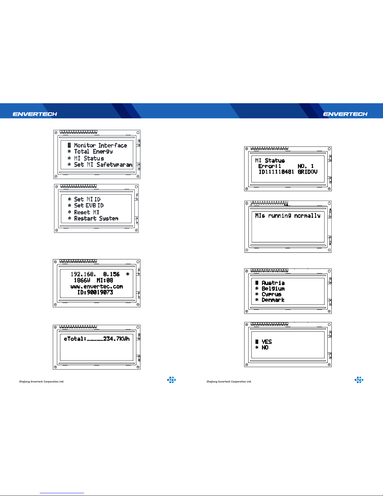
Press “OK”button (Backlight lights up automatically) to enter [Menu Interface]
which is shown as shown below.
* Monitor Interface
* Total Energy
* MI Status
* Set MI SafetyParam
* Set MI ID
* Set EVB ID
* Reset MI
* Restart System
There are a total of eight operations. Press “Up” and “Down” to move the
cursor to view all functions. Press “OK” to enter the function.
3.1.1 Description of LCD
K
A
K
16
1
A
15
1
15
16
A
A
K
K
Number
1
2
3
Description
OK/Exit
Up/Add
Down/Reduce
Button
Number
Description
The green light indicates
normal operation.
The yellow light indicates
being in communicating.
The red light indicates
malfunction.
LED
4
5
6
1
2
3
4
5
6
Page 7
9 10
Step 1. Press “Monitor Interface”, back to main inteface, background light will be
on, and be off after 30 sec. Please be kindly aware that the third line will show our
company website address instead of the version number.
Step 2. Press [Total Energy] to check total energy as belowand press “OK” to go
back to the main interface.
Step 3. Select “MI Status”, it will show below message if there is an error. The third
line displays the problem microinverter ID and fault description. After checking,
press “OK” to return to the main menu.
Without error,it shows as below:
Step 4. Select “Set MI SafetyParam” to set the safety parameters of
microinverters. Press “Up” and “Down” to select the correspondingcountry.
Enter and click “YES”to set the national safety standard, click “NO” to return.
1
16
15
K
K
A
A
1
1615
KK
A
A
A
A
16
15
K
K
1
1
16
15
KK
A
A
15
16
1
KK
A
A
15
16
1
K
K
A
A
A
A
K
K
15
16
1
Page 8
11 12
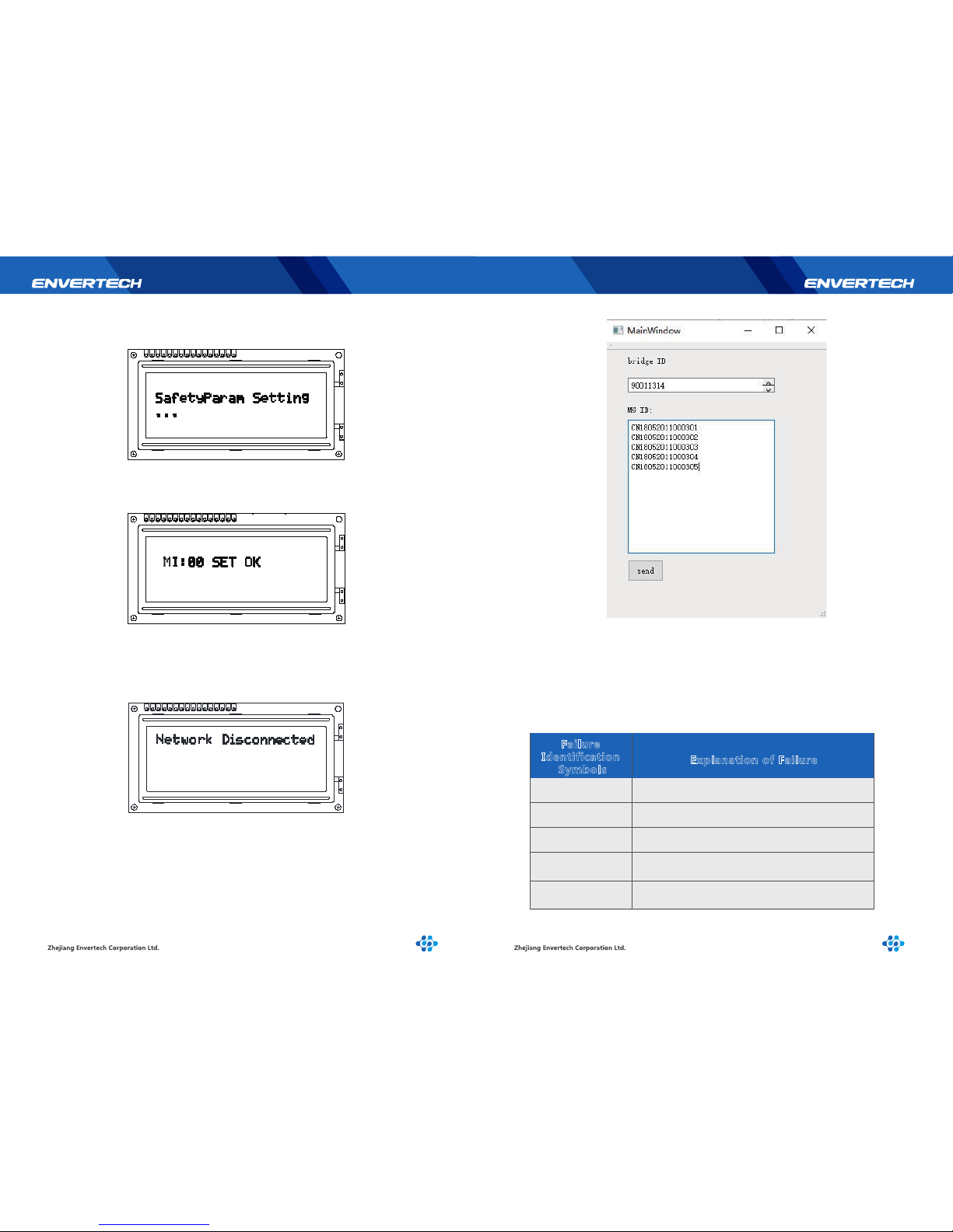
Select “YES”and press “OK”to enter the parameter setting interface. The setting
time is about 1~2 minutes.
After successful setting, the screen will be shown as below. The number after “MI”
is the quantity of the microinverters that complete setting. This interface will remain
until the user presses “OK” and return to the main menu.
Bind successfully, and the monitor will display on the third line“ID SET OK”after
receiving the IDs..
Press “OK”to return after completion.
Step 6. Select “Restart System”, and the monitor will restart in 2 seconds.
3.1.4 Explanation of Malfunction
Step 5. When you select “Set MI ID”, please ensure that the monitor is connected
to the network and is in the same LAN as where the host computer is located. Press
“OK” to have the YES /NO option. Select “NO” to exit and return to the previous
menu. Select“YES” to start this function. If the network is not connected, it will
show the following interface, press “OK” to return to check the network.
If the network runs well, “Please Send MI ID”will pop up on the first line of the
screen. This interface will last 60 seconds and then return automatically.
When the monitor is in this interface, please use the MI binding tool on the
computer to send the corresponding group of IDs to add EnverBridge ID and
microinverter IDs.
15 16
1
KK
A
A
15 16
1
KK
A
A
A
A
KK
1
16
15
Failure
Identification
Symbols
Explanation of Failure
GRIDOV
GRIDUV
GRIDOF
GRIDUF
GRIDSU
Over Voltage
Under Voltage
Over Frequency
Under Frequency
Voltage Fluctuation
Page 9
13 14
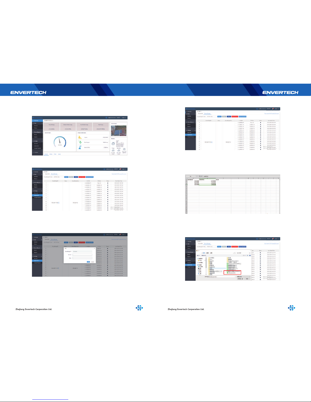
3.2 MI Quick Binding
3.2.1 Login
3.2.2 Select“System Info”under “Settings”, and click “Device Manager”.
3.2.3 Add a Single Microinverter ID
Click “+”behind the EnverBridge ID, input the ID of the neededmicroinverter ID in
the pop-up interface and click “OK”. Wait up to 5 minutes, then refresh the screen,
and it will pop up a window of “Sent successfully”.
3.2.4 Add a Batch of Microinverter IDs
1. Click “Batch Add MI S/N Template Download” on the upper right corner of the
screen and download.
2. Input the microinverter IDs which need to be added to the template. On the left
side of the following template is the EnverBridge ID, and on the right side is the
microinverter ID.
3. Click“Batch Add MI S/N”, select the modified template and click “Open”.
Wait up to 5 minutes, and then refresh the page, it will show “Sent successfully“.
Page 10
15 16
Safety checks should be performed at least every 12 months by manufacturer’s
qualified person who has adequate training, knowledge, and practical experience to
perform these checks. The data should be recorded in an equipment log. If the device
is not functioning properly or fails in any of the tests, the device has to be repaired.
4 Basic Operations
4.1 Safety Checks
For more information of safety checks, please see below the three safety instructions
of this manual.
4.2 Maintain Periodically
The problems can be detected according to what is displayed on the LCD screen:
1. When the LCD screen shows the number of MI devices is less than those connected
to EVB202 for a long time, it is suggested to check whether a certain MI device is in
problem (the specific problem MI can be found from the webportal EnverPortal or
from local monitoring);
2. According to the fault info, technical personnel can accurately find the faulty
microinverterand do maintainence.
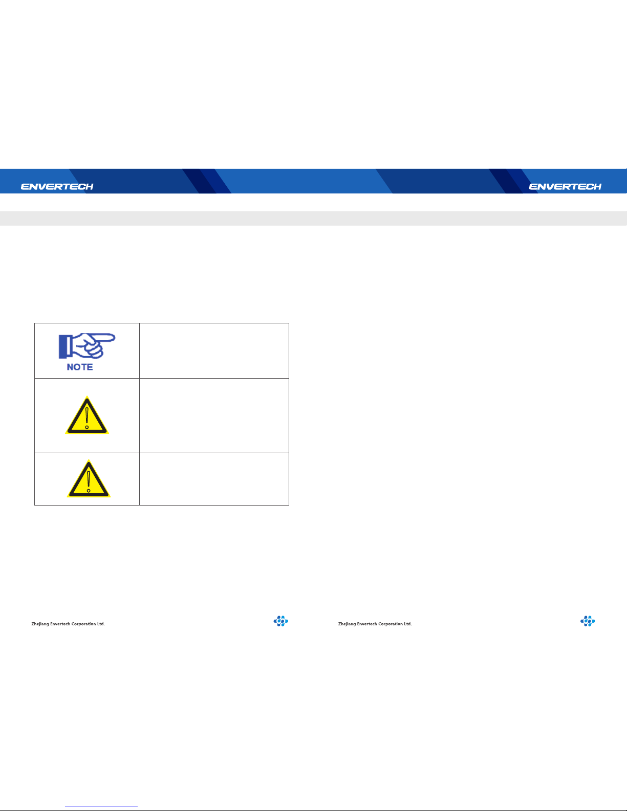
The “Note” mark in this manual indicates
important product information.
Do not attempt to repair the Envertech
monitoring device without authorization,
because it does not contain parts available
for users to repair. If the microinverter fails,
please contact Envertech customer service.
Please ensure that all power is off and there
is no electric current when connecting
Envertech monitoring device.
4.3 Common Problems
NOTE
WARNING
WARNING
!
Zhejiang Envertech Corporation Ltd.
Tel: 0086-0579 89266326
Add: 24th Floor, Jintong Mansion, Center of Headquarters,
YongKang City, Zhejiang Province, China
Web: www.envertec.com
Sales Hotline: 400-666-5819
!
5 About us
 Loading...