

Page 1
USER M ANUAL ( En glis h)
VI DE O DOO R PHONE SYSTEM
It em No. : 13505
The design and specifications can be changed without notice to users.
Copyright of this manual is reserved.
Ver sion2. 0.1.1 .3.2 8
Page 2
CONTENTS
- - - - - - - - - - - - - - - - - - - - - - - - - - - - 1
- - - - - - - - - - - - - - - - - - - - - - - - - - 1
- - - - - - - - - - - - - - - - - - - - - - - - - - - 2
- - - - - - - - - - - - - - - - - - - - - - - 2
3.2 Placing Name Label
- - - - - - - - - - - - - - - - - - - - - - - - - - 3
- - - - - - - - - - - - - - - - - - - - - - 3
- - - - - - - - - - - - - - - - - - - - - - - - - 4
- - - - - - - - - - - - - - - - - - - 4
- - - - - - - - - - - - - - - - - - - - - - - - - - - - 4
- - - - - - - - - - - - - - - - - - - - - - 5
4.2.1 Door Lock Controlled by Internal Power - - - - - - - 5
4.2.2 Door Lock Controlled by Dry Contact - - - - - - - - - - 5
4.2.3 How to setup the unlock parameter in Monitor - - 6
- - - - - - - - - - - - - - - - 7
- - - - - - - - - - - - - - - - - - - 8
4.4.1 Basic IN-OUT Wiring Mode - - - - - - - - - - - - - - - - 8
- - - - - - - - - - - - - - - - - - - - - - - - - - - - - - - - - - 9
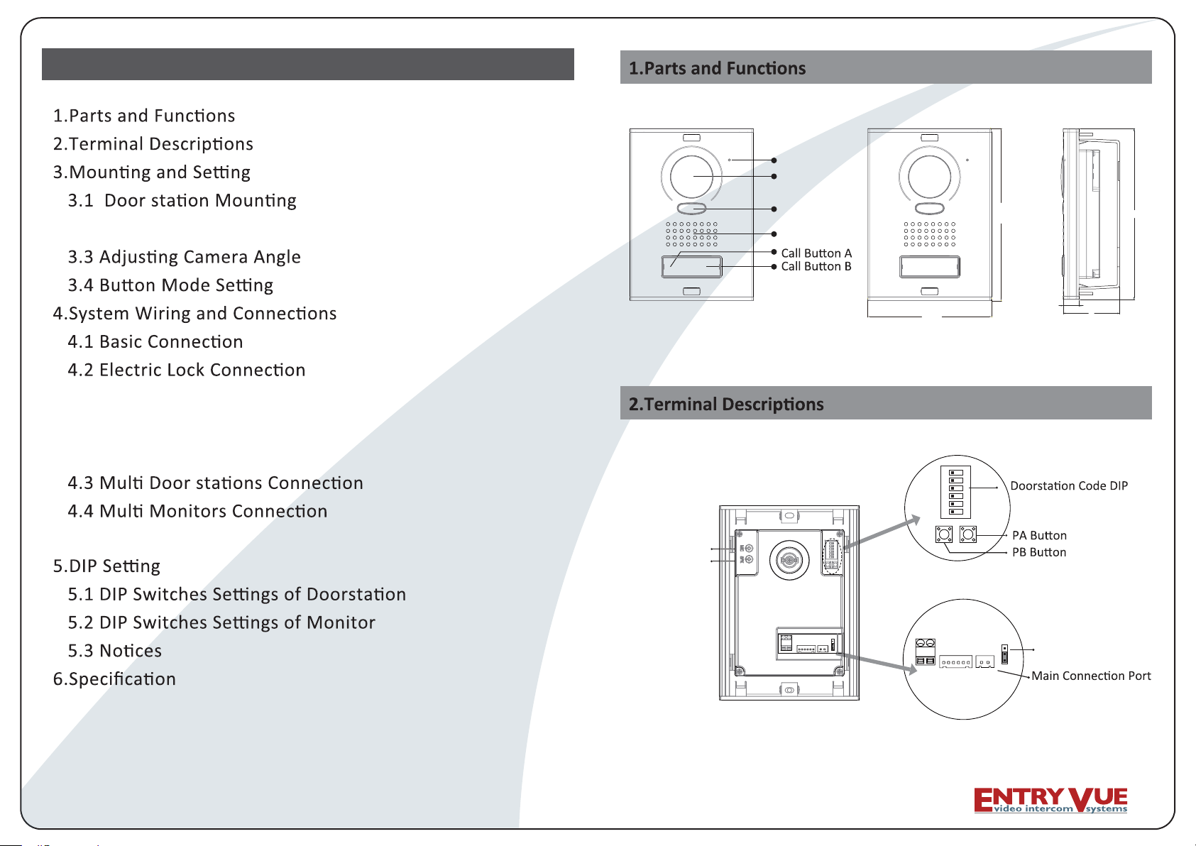
Microphone
Camera Lens
LED Indicator
Speaker
128mm
1 2 3 4 5
ON DIP
SET
6
MIC adjustment
SPK adjustment
178mm
16.5mm
59mm
178mm
- - - - - - - - - - - - 9
- - - - - - - - - - - - -- - 9
- - - - - - - - - - - - - - - - - - - - - - - - - - - - - - - - - 10
- - - - - - - - - - - - - - - - - - - - - - - - - - - - - - - 11
-1-
BUS
CN-LK
LK-(GND)
+12V
N.O.
EB-
LK+(COM)
EB+
RS485
T/R+
JP-LK
Lock Control Jumper
123
T/R-
Page 3
+12V:
•
•
•
•
•
•
•
•
•
•
•
•
•
12VDC power output.
LK-(GND):
LK+(COM):
NO.:
EB+:
EB-:
JP-LK:
T/R-:
T/R+:
SET:
PA:
PB:
Bus(
power ground.
electronical load relay normally open contact(refer to DT technical guide for
Exit buton.
DIP
L1,L2): non-polarised bus line.
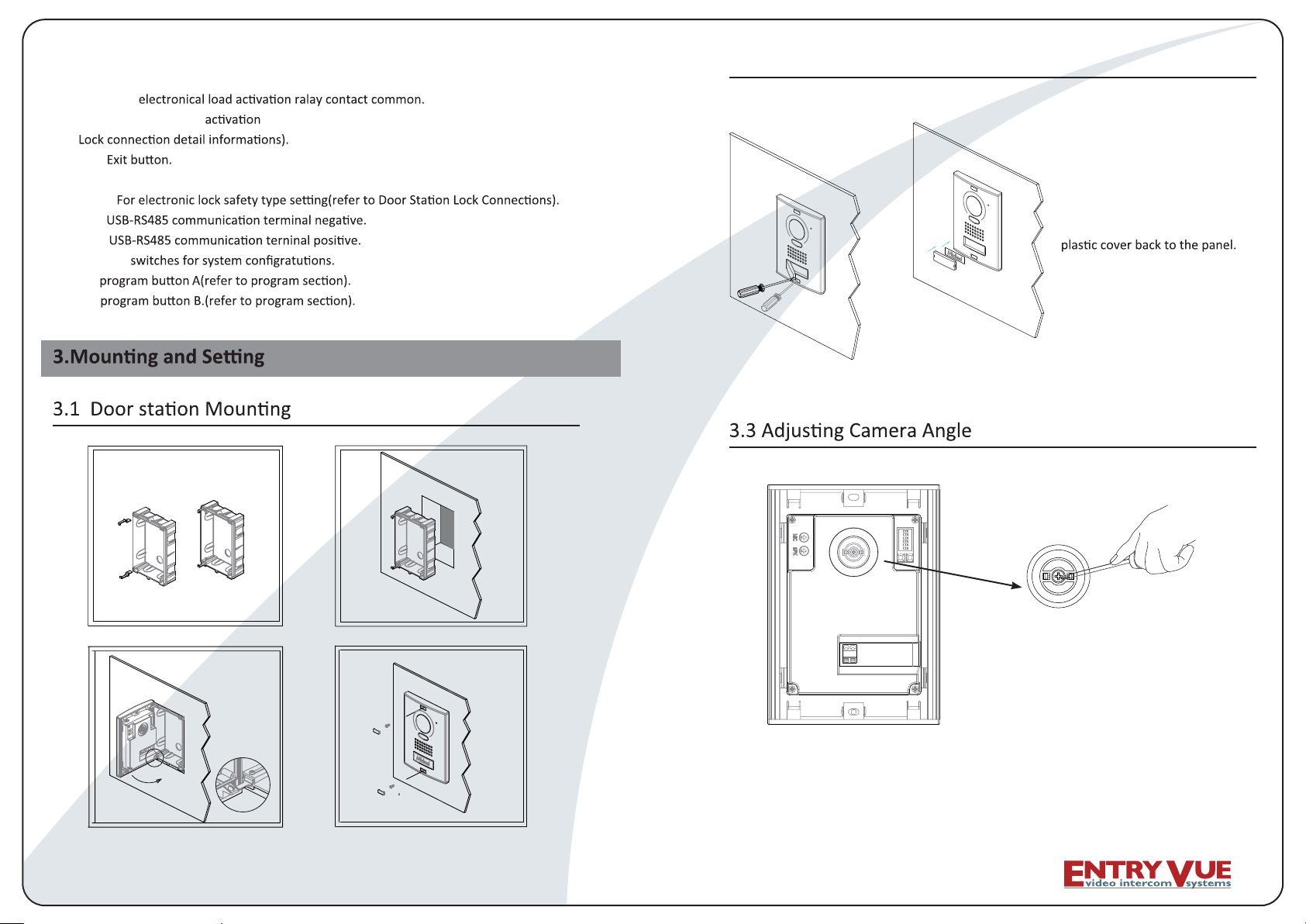
21
3.2 Placing Name Label
Use a screwdriver to open the
,revoc lebal eman tnerapsnart
insert a name paper, then put the
3
-2-
4
use one hand to hold the unit and another
hand with a screwdriver to loosen the screw
and then adjust the angle of the camera ,then
fi x the screw.
-3-
Page 4

Y
• Single Mode: that means the door only has one can only call the monitor with
it's code among 00~15.please refer to 5.2.
Double
•
of the monitor
Single
1.
Mode: that means the door has two A can call the adress 00~15
r.please refer to 5.2.
set the DIP swiches of Bit 3 on door station to 'on' state (refer to 5.1), single
2.
Double
.set the DIP swiches of Bit 3 on door to 'off' state (refer to 5.1),double
4.2.1 Door Lock Controlled by Internal Power
Note:
1. Only available to power on the unlock type os electoric lock.
2. The door lock is limited to 12V, and holding current must be less than 250mA.
3.
4. The Unlock Mode Parameter of Monitor must be set to 0 (by default).
L1
Jumper posi on in 1-2
Connect to DPS
L2
BUS
+12V
LK - (GND)
LK+(COM)
N.O.
EB -
EB+
T/R -
T/R+
RS-485
JP-LK
1
2
3
LOCK
EB
4.2.2 Door Lock Controlled with Dry Contact
Note:
1. The external power supply must be used according to the lock.
2. The inside relay contact is restricted to AC or DC 24V/3A.
3. The jumper must be taken off
4. Setup the Unlock Mode of Monitor for different lock types.
• Power-on-to-unlock type:Unlock Mode=0 (by default)
• Power-off-to-unlock type:Unlock Mode=1
monitor
cut the red wire
L1
DPS
+
-
AC~
PS4
Take off the Jum
Connect to DPS
per
-4-
L2
POWER
SUPPLY
BUS
-5-
+12V
LK - (GND)
LK+(COM)
N.O.
EB -
EB+
T/R -
T/R+
RS-485
LOCK
JP-LK
1
2
3
Page 5

4.2.3 How to setup the unlock parameter in Monitor
monitor
intercom
setup
exit
1.Press MENU bu on twice
to en te r th e MAI N MEN U
page, then press setup.
Unlock Time 1
Unlock Mode 0
Exit
6.Use
item, use
/ to select the
to change
/
the value of the item. Select
press MENU
Exit
y.
Outdoor Tone -- 01
Intercom Tone -- 05
Monitor Time -- 1min
Advanced Set...
Auto Record -- OFF
Exit
2.Select Advanced Set...
and press MENU to
enter is required.
Hardware ver 0302
Software ver 0168
Voltage 22.4V
Manufacture 00.0T
Restore to default
Exit
5.Press UNLOCK n
and hold for 2s.
Password:
0
* * *
3.The default password is
2008. Press
change the lock, Press
/ to
/
bu on to select the loca on,a er
finishing, press MENU to
enter next step.
Slave Addr Set -- 0
Guard Unit Set -- 0
Date/Time Set...
Other Settings...
Information...
Exit
4.Select
and press MENU to
enter next page.
monitors
DPS
PS5
85~260VAC
Note:
3.the above
are not fi t for T-views series monitors. Please refer to T-views series
monitor user manual to how to set the unlock parameter.
-6-
y, so you only need to set on one monitor.
4# Camera
ID=11
ON
1 2 3 4 5 6
L1 L2 L1 L2 L1 L2
ID=01
ON
1 2 3 456
2# Camera3# Camera
ID=10
ON
1 2 3 456
1# Camera
ID=00
ON
1 2 3 4 5 6
L1 L2
-7-
Page 6

5.DIP
4.4.1 Basic IN-OUT Wiring Mode
Attention: You must follow the dip switch settings in the table on page 11 .
So, 1st monitor all switches down, 2nd monitor switch 1 up, 3rd monitor
switch 2 up, etc.
ON
1 2 3 456
Code=31, DIP-6=on
ON
6
1 2 3 4 5
Code=30, DIP-6=off
ON
1 2 3 4 5
6
Code=0, DIP-6=off
DPS
monitor
monitor
monitor
PS5
ON
12345 6
ON(1)
ON
=
OFF(0)
ON
=
5.1 DIP
Total 6 bits in the DIP switches can be co
installaon, but the power supply needs to be restated whenever the switches have been modified.
•
two bit must be set correctly,
to 10, the fourth one set to 1
• Bit-3: Single mode or double line mode for door set 'on' state to be
ff
• Bit-4:reserved and unused.
• Bit-5: Unlocking quick by default it is set to 0, for 1 second unlocking set to 1 for 5
seconds.
• Bit-6: reserved and unused.
5.2 DIP
Note:
ID=00
ON
1 2 3 4 5 6
85~260AC
-8-
There are 6 bit switches in total. The DIP switches are used to configure the User Code for each
Monitor.
Bit-6 is line terminal switch, which have to be set to ON if the Monitor is at the end of the line(bus),
otherwise set to OFF.
Bit state Setting Bit state Setting
6
The moni tor
is at the end
of the bus.
ON
123 4 5
not at the end
6
of the bus.
si rotinom ehT
ON
123 4 5
-9-
Page 7

The value is from 0 to 31, which have 32 different codes .
Bit state User Code Bit state User Code Bit state User Code
ON
1 2 3 4
ON
1 2 3 4
ON
1 2 3 4
ON
1 2 3 456
ON
1 2 3 456
ON
1 2 3 4 5
ON
1 2 3 456
ON
1 2 3 4 5 6
ON
1 2 3 4
ON
1 2 3 4 5 6
ON
1 2 3 4 5 6
ON
5 6
5
6
5
6
6
5 6
Code=10 Code=21
1 2 3 4 5
ON
1 2 3 4
ON
1 2 3 456
ON
1 2 3 4 5 6
ON
1 2 3 4 5 6
ON
1 2 3 4 5 6
ON
1 2 3 4
ON
1 2 3 4
ON
1 2 3 4
ON
1 2 3 4
ON
1 2 3 4
6
21=edoC1=edoC
5 6
31=edoC2=edoC
41=edoC3=edoC
51=edoC4=edoC
61=edoC5=edoC
71=edoC6=edoC
5
6
81=edoC7=edoC
5 6
91=edoC8=edoC
5 6
02=edoC9=edoC
5 6
5 6
ON
1 2 3 4
5 6
ON
5 6
1 2 3 4
ON
5 6
1 2 3 4
ON
1 2 3 456
ON
1 2 3 4 5 6
ON
1 2 3 4 5 6
ON
5 6
1 2 3 4
ON
1 2 3 4 5 6
ON
1 2 3 4 5 6
ON
5 6
1 2 3 4
22=edoC11=edoC0=edoC
Code=23
Code=24
Code=25
Code=26
Code=27
Code=28
Code=29
Code=30
Code=31
)rewoP lanretnI(Am003 ,cdV21 :ylppus rewoP kcoL
gnikrow ni W21 ,ybdnats ni W1 :noitmusnoC rewoP
A5.1 cd V84 .xaM :tcatnoc yrd MOC ,ON
rotinoM yb tes ,sdnoces 9 ot 1 :emit gnikcolnU
Cº54 ~ Cº01- :erutarepmet gnikroW
Note:
1. If the
mode is set to single mode for door
2. If the mode is set to double for door
response A must set the user code
B
A
-10-
-11-
 Loading...