

Page 1

iPAK2 Technical Manual
Welding control for MFDC spot, projection, roll-spot, seam and multi-welding applications
For firmware version 2.01
Page 2

iPAK2 Technical Manual 2
iPAK2 Technical Manual
Copyright © 2019 BF ENTRON Ltd. and/or its affiliates. All rights reserved.
The information in this manual is subject to change.
BF ENTRON assumes no responsibility for any errors that may appear in this manual.
BF ENTRON assumes no responsibility for any injury, loss or damage caused by improper installation,
use or application of the iPAK2 welding control
The reproduction, transmission or use of this document or contents is not permitted without express
authority from BF ENTRON
BF ENTRON's trademarks and trade dress may not be used in connection with any product or service
that is not BF ENTRON's, in any manner that is likely to cause confusion among customers or in any
manner that disparages or discredits BF ENTRON. All other trademarks not owned by BF ENTRON are
the property of their respective owners, who may or may not be affiliated with, connected to, or
sponsored by BF ENTRON.
BF ENTRON Ltd.
Building 80 Bay 1
First Avenue
The Pensnett Estate
Kingswinford
West Midlands DY6 7FQ
Phone +44 (0)1384 455401 • Fax +44 (0)1384 455551
www.entroncontrols.com
Issue Date Comment
2.00 27-02-19 Initial release
2.00.01 13-06-19 Minor errata corrected
2.00.02 19-06-19 Corrected weld program time range.
2.01 8-08-19 Added Presqueeze to all modes
England
Page 3

iPAK2 Technical Manual 3
IMPORTANT SAFETY INSTRUCTIONS
READ ALL INSTRUCTIONS BEFORE USING THE iPAK2
WARNING
DO NOT DISASSEMBLE, REPAIR, OR MODIFY THE iPAK2. These actions can cause electric shock and fire.
Use only as described in this manual. Use only BF ENTRON recommended accessories and
replacement parts.
Stop operation if any problems occur. If the equipment is not working as it should, has been dropped,
damaged, left outdoors, or been in contact with water, contact BF ENTRON.
Only apply the specified power. Application of a voltage or current beyond the specified range can
cause electric shock or fire.
Do not use damaged plugs or connecting cables.
Keep water and water containers away from the iPAK2. Water ingress can cause a short circuit, electric
shock, or fire.
Do not insert objects into openings. Do not use with any opening blocked; keep free of dust and debris.
Do not install the iPAK2 in any of the following environments
o damp environments where humidity is 90% or higher.
o dusty environments.
o environments where chemicals are handled.
o environments near a high-frequency noise source.
o hot or cold environments where temperatures are above 40°C or below 0°C, or environments
where water will condense.
Page 4
iPAK2 Technical Manual 4
Contents
Section 1
Introduction…………………………………………………………………………………………...…5
Section 2
Getting started………...……………………………………………………………..………………13
Section 3
Inputs and outputs…………………….…....……………………………………………………19
Section 4
Discrete I/O…………… ……………..…….…………………………………………………….……21
Section 5
MODBUS I/O…………………..…….………………………………………………………….….…...24
Section 6
Weld control…………………..…….…………………………………………….…………………....30
Section 7
Electrode management…………………..…….……………………….…………….………38
Section 8
Status information…………………………………………………………….……….………….46
Section 9
History log…………………..…….…………………………………………………………………..…49
Section 10
Multiwelding…………………..…….………………………………………………….…..…………..50
Section 11
Seam welding………………..…….……………………………………………………...…………..54
Section 12
Configuration…………………..…….……………………………………………….….……………62
Section 13
Programming…………………..…….………………………………………………….……….……65
Section 14
Tutorials…………………..…….…………………………………………………………….…………...82
Section 15
Appendix…………………..…….……………………………………………………………….…….…92
Section 16
Terminology……………..…….…………………………………………………………………….…96
Page 5
Section 1 Introduction 5
Introduction
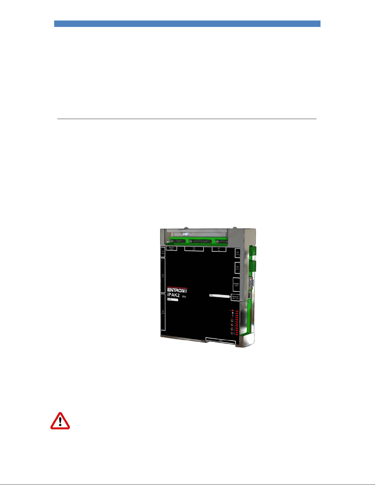
The iPAK2 controller is suitable for MFDC spot, projection, roll-spot, seam and multi-welding welding
applications.
The controller supports:
pre-heat, main heat and post-heat intervals
force profiles
multi-gun, multi-air valve applications
multiple electrodes
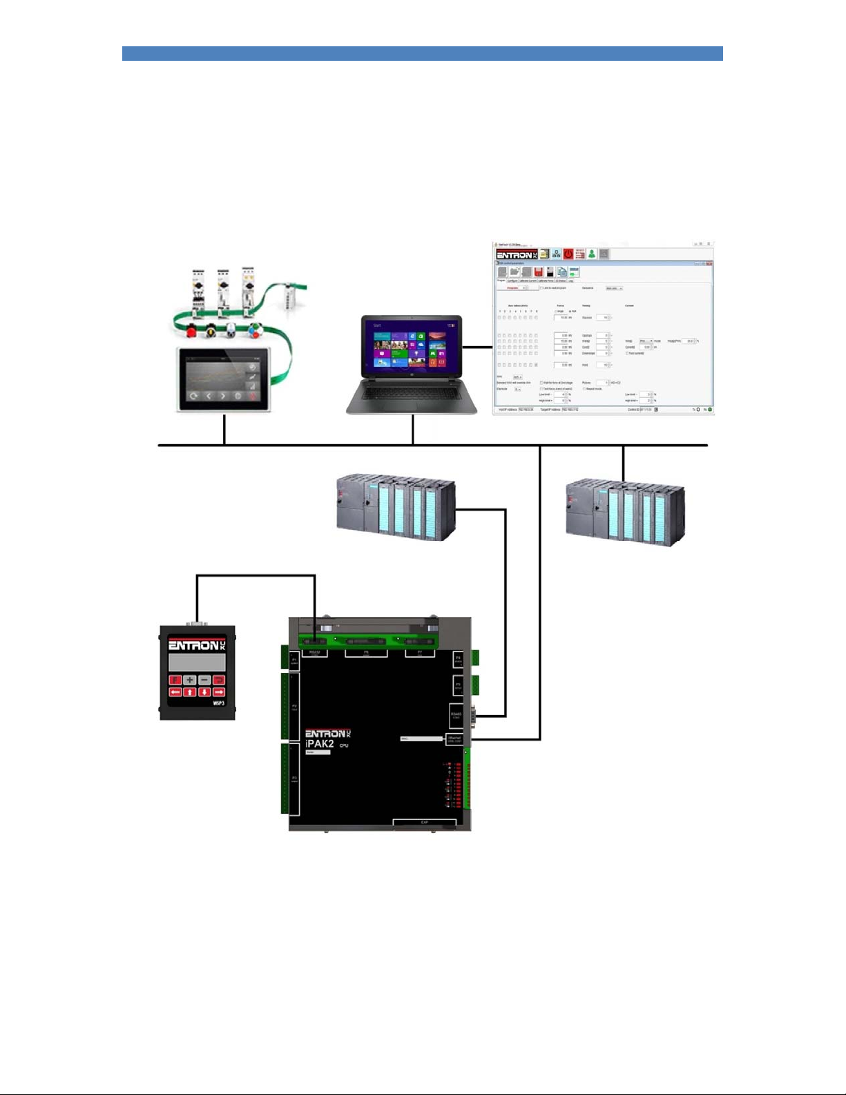
The iPAK2 has multiple communication and control options and can be configured by a number of
programming options. The Ethernet port supports simultaneous programming and control via a single
physical cable.
Short-circuit proof outputs and a guided-contact pilot relay provides enhanced safety. Connection to the
power system is via a single ribbon cable. Analog inputs and outputs can be used to drive a proportional
air regulator valve for force control.
Operation in Standard mode provides a basic set of features for simple applications. Extended mode
adds advanced features for more demanding applications. Choose between Standard or Extended
features (Section 12 Configuration). The iPAK2 must be restarted after changing this setting.
Page 6

Section 1 Introduction 6
Features
NetFlash programming
WSP3 programming
Ethernet 1
RS232
RS485
MODBUS TCP/IP
MODBUS RTU
Analogue inputs 2 2
Analogue outputs 2 1
Discrete inputs 16
Discrete outputs 3 16
Weld programmes 256
Pre-heat
Main heat
Post-heat 5
Slope
Constant current
Cascade/Mux 5 8
Multi air valve
4, 5
8
Aux valves 7
Force profile 5
Electrodes 8
Real-time clock
Data log (spot welds) 6000
Expansion
Analog control mode 5
1
Two ports
2
0 to 10 V
3
24 V dc, short-circuit proof, monitored
4
Guided contact safety relay, monitored
5
Extended feature
The extended features can be enabled for greater flexibility or more demanding applications.
Page 7
Section 1 Introduction 7
Weld parameters
Prequeeze
Squeeze
Pre-heat
Cool1
Upslope
Main heat
Cool2
Downslope
Pulses
Post-heat 1
Hold
Off
WAV selection 1
Motor control
Aux valve control
Retract/Hi-lift
Electrode selection 1
Force profile 1
Current monitor
Force monitor
Spot weld
Roll-spot weld 1
Seam weld 1
1
Extended feature
Part number
Model Part number
iPAK2 01-70-27
Page 8
Section 1 Introduction 8
Programming options
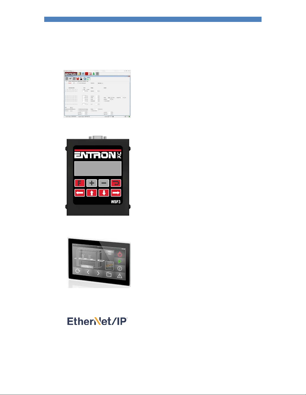
1.NetFlash
This PC-compatible program displays and allows editing of all
welding parameters and status information.
In addition to programming, NetFlash provides backup/restore
functions for control data, live data logging to a file and a utility for
updating the firmware in the iPAK2.
2. WSP3 Pendant
iPAK2 series controls work with the same WSP3 pendant that is
used with EN7000, WS2003 and iPAK (v1). Access to all
parameters is provided, plus diagnostic indication.
3. MODBUS
A PLC or HMI MODBUS master can be used to program, control
and monitor an iPAK2. All parameters are directly mapped to
MODBUS registers for easy access. Both MODBUS-TCP/IP
(Ethernet) and MODBUS-RTU (RS485) protocols are supported.
4. Ethernet/IP
An optional adapter card can be fitted to the expansion port,
providing full data access via the EtherNet/IP protocol.
Page 9
Section 1 Introduction 9
Communications
Ethernet
RS485 RS232
Page 10
Section 1 Introduction 10
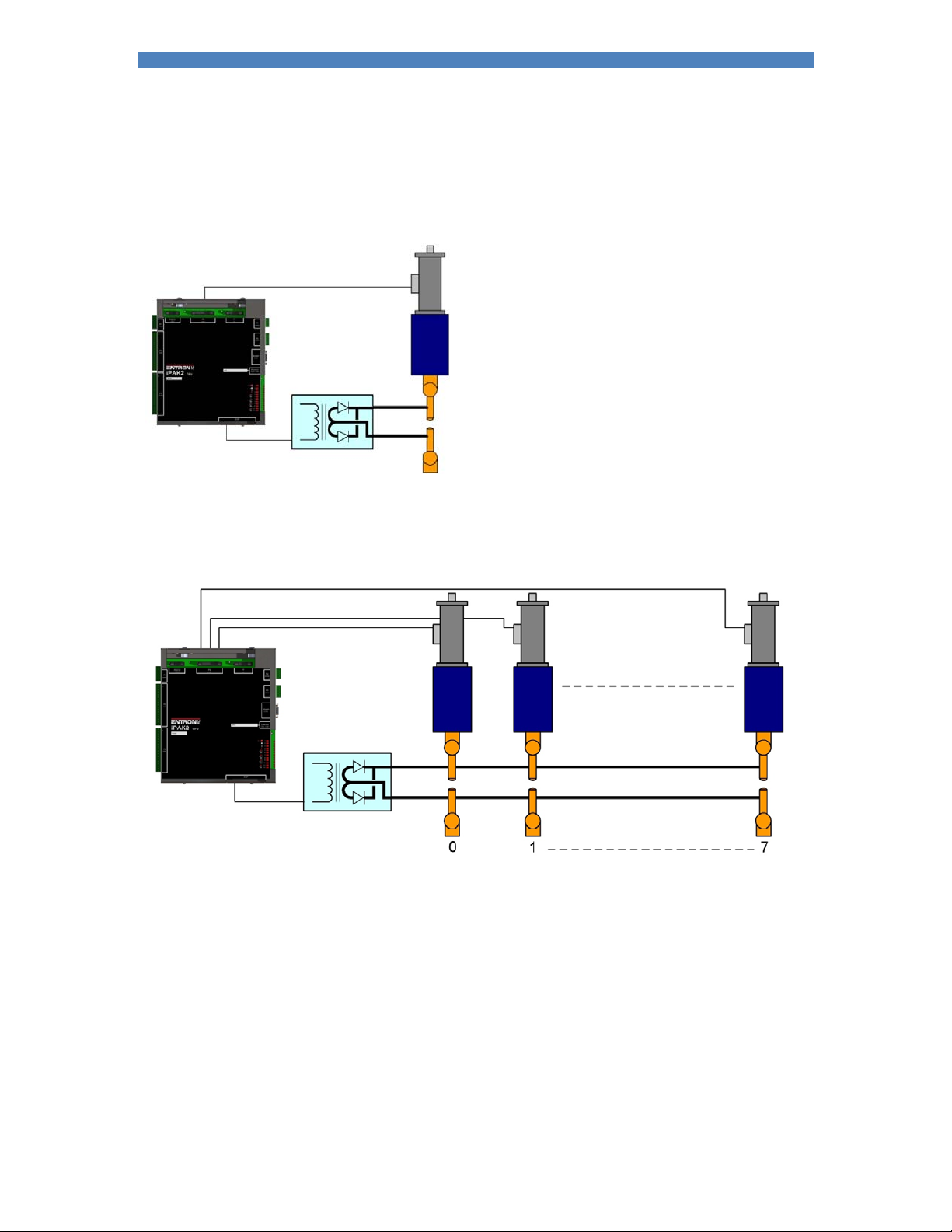
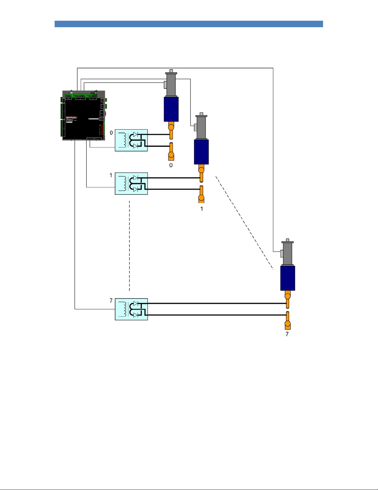
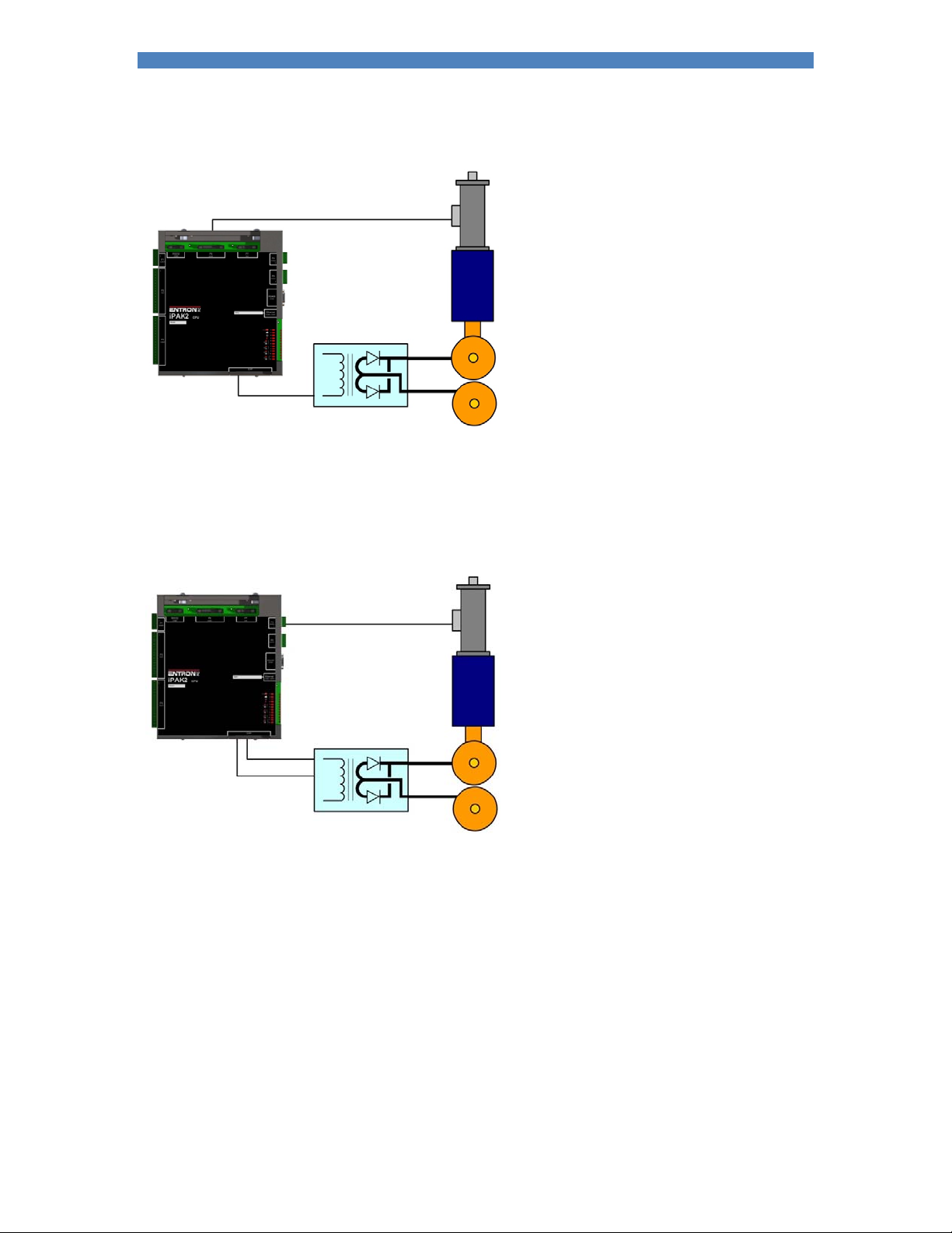
Applications
Standard machines, portable/manual guns, robot guns, multi-welders and seam welders.
Standard machine
Multi-head machine. Up to eight cylinders, cascade or independent firing.
Page 11
Section 1 Introduction 11
Multi-welder. Up to 8 transformers and cylinders, cascade or independent firing.
Page 12
Section 1 Introduction 12
Seam welder with one transformer
Seam welder with a multi-tap transformer
Page 13

Section 2 Getting started 13
Getting started
iPAK2 mounts directly onto an iPAK inverter. The inverters have maximum primary current ratings as
follows:
150 A
360 A
600 A
1000 A
1500 A (LMI)
For higher currents, multiple LMI modules can be connected together. The standard iPAK family
operates with a supply voltage in the range 380-480V AC but lower and higher voltage inverters are
available.
Page 14

Section 2 Getting started 14
Control connectors
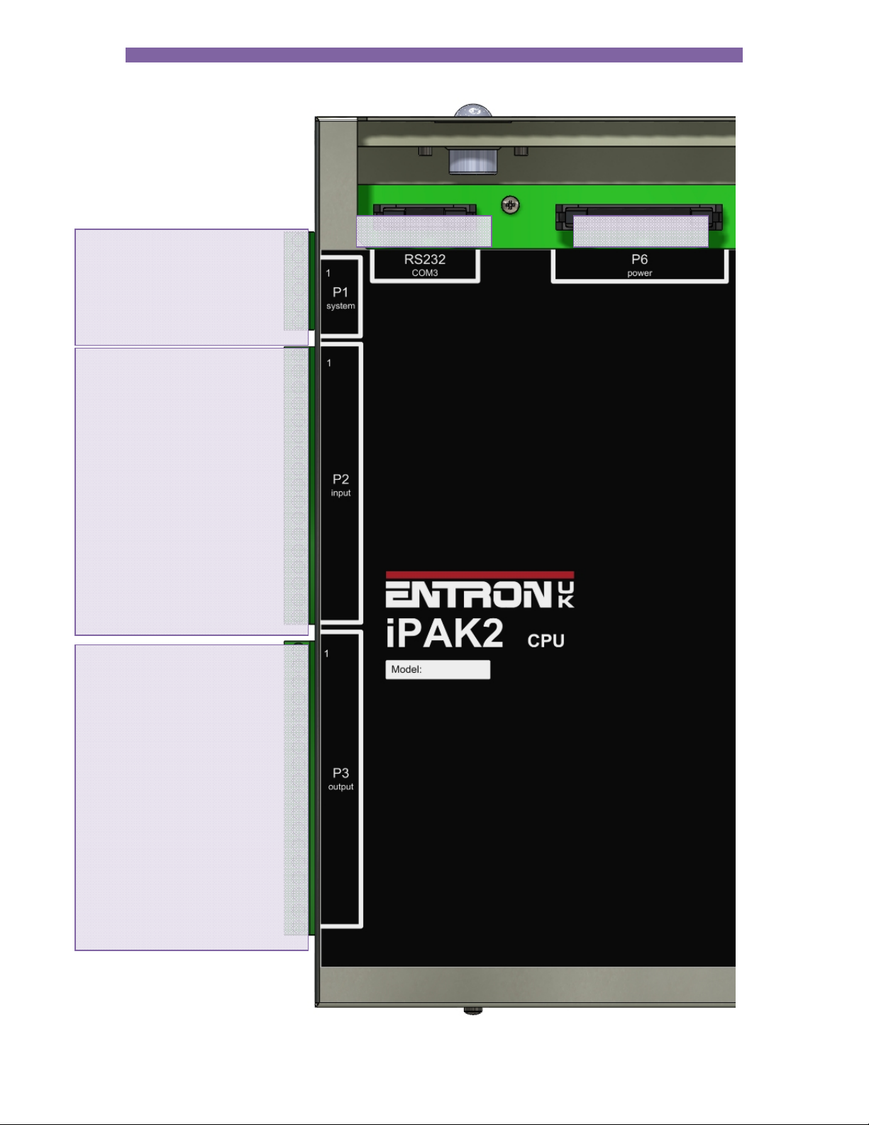
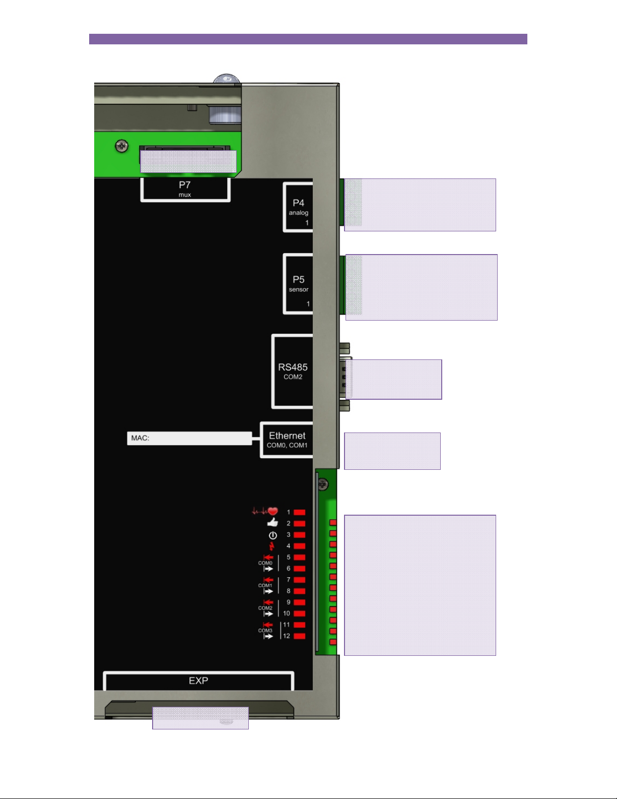
Connectors P1, P2, P3, P4 and P5 are two-part terminals, for use with wires up to 1mm2.
The RS232 port is used to connect a WSP3 programming pendant or a PC. A ribbon cable assembly is
available for converting to the standard 9-way D-sub style of connector.
Connector P6 is used internally to connect to the inverter power pack, and is not used for users
connections.
Connector P7 is used for MUX driver cards on systems with more than one transformer.
Page 15

Section 2 Getting started 15
Power connectors
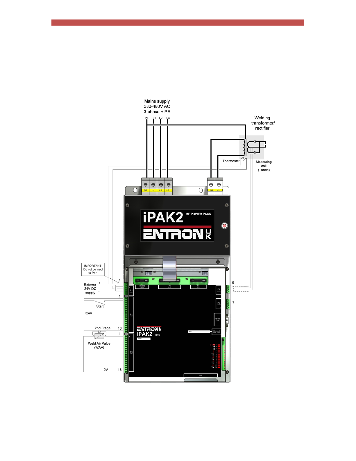
A 3-phase supply via a suitable protective device (such as a circuit breaker) should be connected to the
inverter as shown (Terminals L1, L2, L3, PE). A suitable MF welding transformer/rectifier should be
connected to the inverter at terminals H1 and H2. The transformer must also be connected to the
protective earth (PE).
Additional earthing and/or a protective device is required for the secondary circuit depending on the
application.
These tasks must only be carried out by qualified personnel.
Page 16
Section 2 Getting started 16
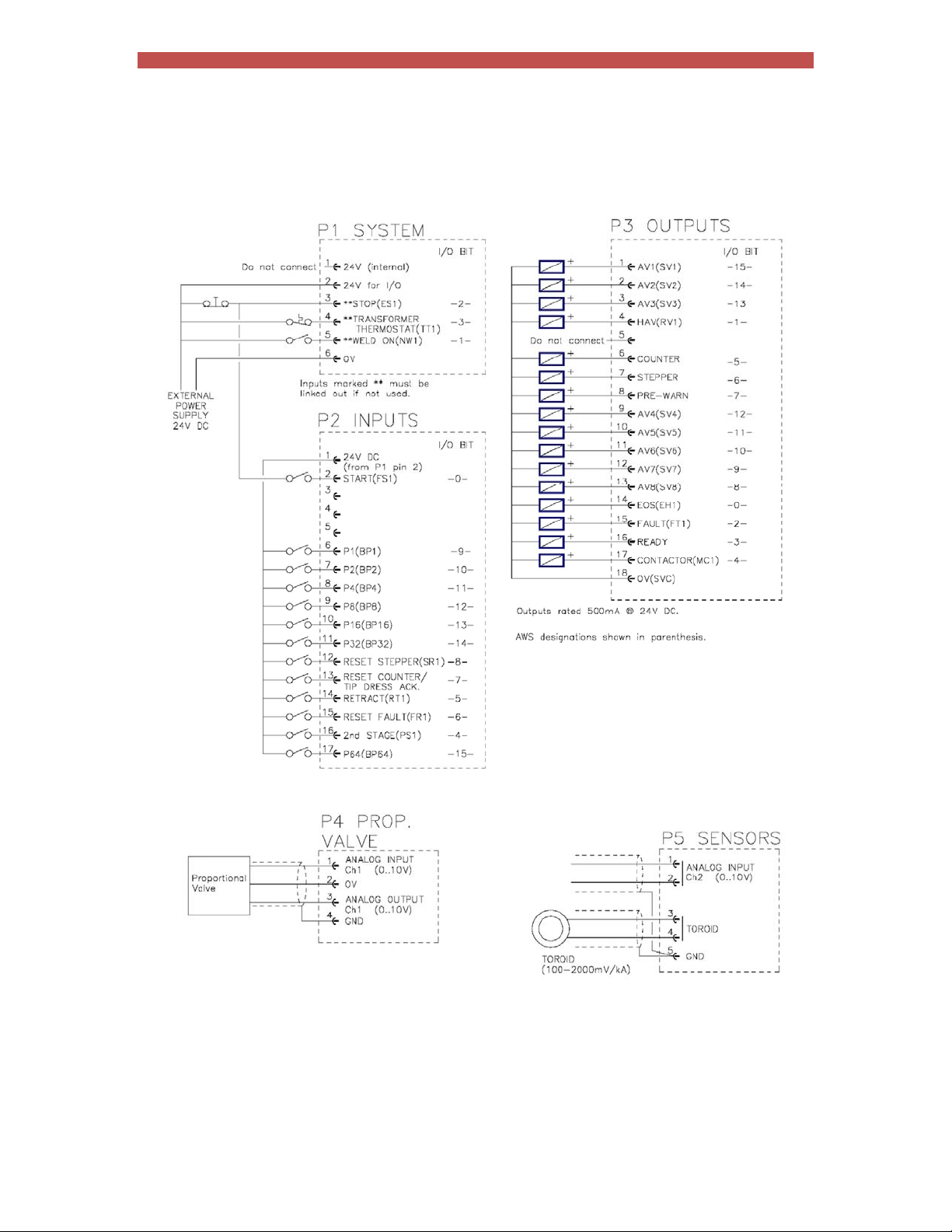
User’s connections (discrete)
Page 17
Section 2 Getting started 17
Initialisation
Make the basic connections as shown below. Additional connections may be required
depending on the application.
Make sure there is sufficient air pressure and cooling water where necessary.
Section 13 Programming: switch on then use the ‘Initialise all data’ function to clear the
iPAK2’s memory.
Section 12 Configuration: set the Configuration parameters appropriately for the application.
Page 18

Section 2 Getting started 18
Section 13 Programming: edit program 0 to set up a basic weld sequence e.g. Squeeze =
200, Main heat = 100, Hold = 200, Pulses=1, and Main mode = P/W. A welding operation
should be possible at this stage. Begin by using the gun short-circuit. The iPAK2 should report
the measured current on the diagnostic display.
Section 7 Electrode management: perform the current and CCC calibration procedures.
Make any other adjustments which may be required and set up other programmes for welding.
Page 19
Section 3 Inputs and outputs 19
Inputs and outputs
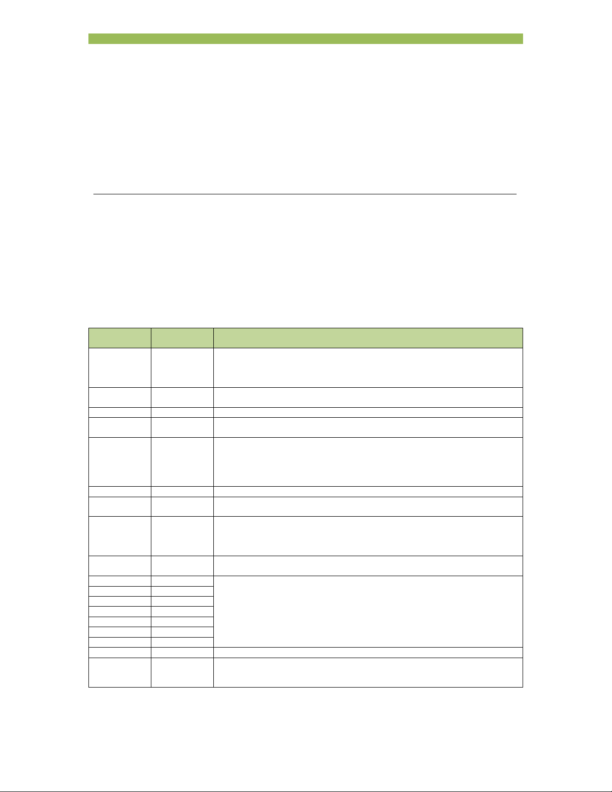
iPAK2 uses a number of inputs and outputs to control and monitor the weld sequence.
Inputs
Input AWS
Start FS1 When this input is activated a weld sequence begins. If the input is removed
Weld on NW1 This input enables the weld current. If this input is inactive a weld sequence will
Stop ES1 Sequencing is inhibited or aborted if this input is not active.
Thermal TT1 This input is usually connected to a normally closed thermal contact attached to
2nd stage PS1 If enabled, iPAK2 checks that the 2nd Stage signal is present before
Retract RT1 This input is used to control the Retract function.
Reset fault FR1 This input resets the Fault output and clears the status messages. Only
Reset
counter/tip
dress
acknowledge
Reset
2
stepper
P1 BP1 Program select inputs. Weld program selection is made by applying the binary
P2 BP2
P4 BP4
P8 BP8
P16 BP16
P32 BP32
P64 BP64
Toroid Input for the toroid. Resistance must be in the range 10 to 300 Ohms.
Analog 0 to 10 V analog input. Can be used to monitor a proportional air regulator valve
designation
Used to reset the counter(s) or acknowledge a tip dress request.
1
SR1 Used to reset the stepper(s).
Description
during the Squeeze interval the sequence is aborted. If the input is maintained
through the Squeeze interval but switched off subsequently, the sequence
terminates normally.
not produce any current.
the weld transformer. Sequencing is inhibited if this input is not active.
proceeding to weld. The checking is programmable to take place either before
or after the Squeeze interval. If the signal is not present iPAK2 waits for the
signal before it proceeds. If the Start signal is removed while waiting, the
sequence is aborted.
momentary application is required (minimum time 40ms).
code for the required program. Programs 0 to 127 can be selected (programs
128 to 255 can still be selected internally or via the fieldbus).
If the ‘key-switch’ security option is selected, then input P64 (on the discrete
interface only) is not available. In this case, programs 0 to 63 can be selected
(programs 64 to 255 can still be selected internally or via the fieldbus).
output or other sensor for force control and monitoring.
input in ANALOG mode.
Also used as the control
Page 20
Section 3 Inputs and outputs 20
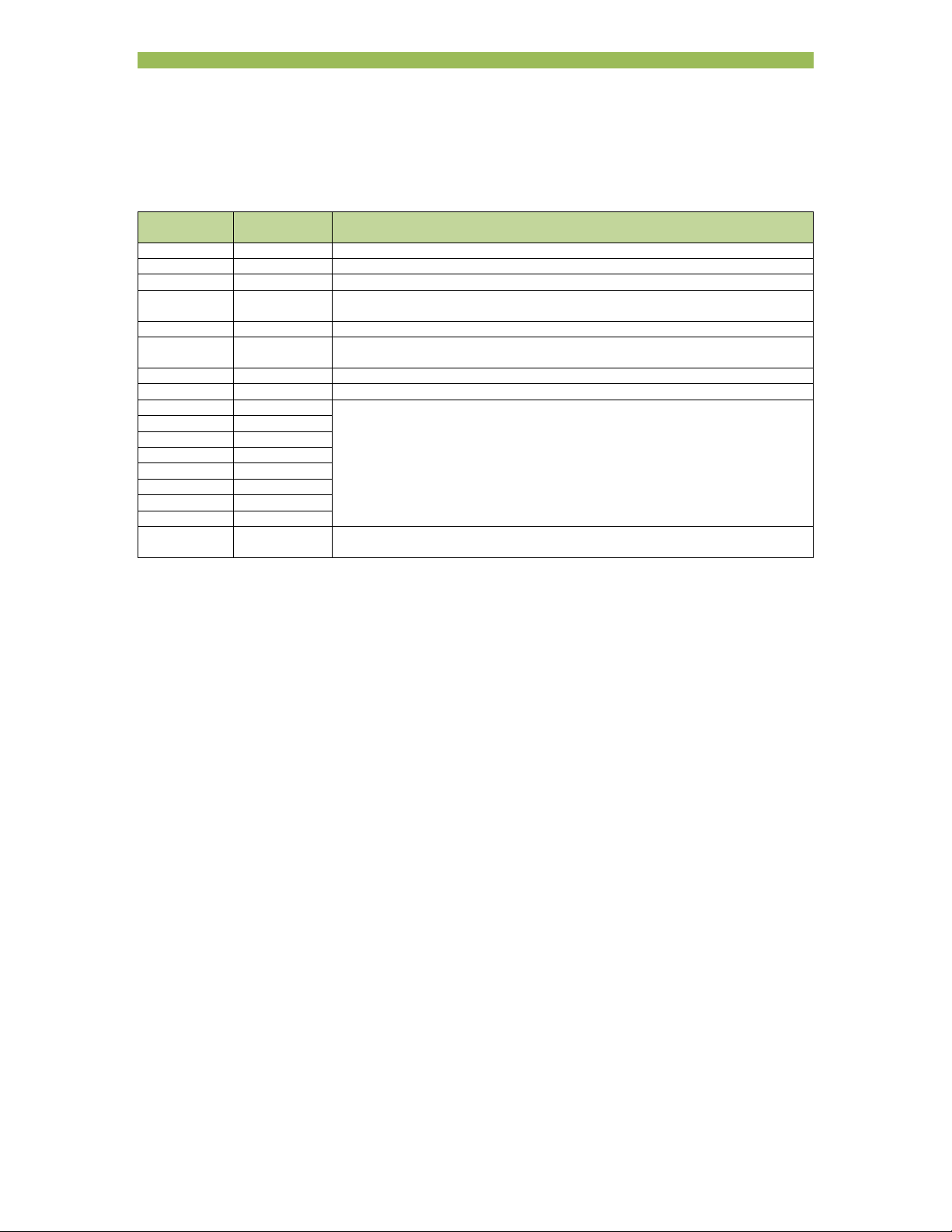
Outputs
Output AWS
Description
designation
EOS EH1 This output switches on to indicate the end of the weld sequence.
HAV RV1 Used in conjunction with the Retract input to control the welding head.
Fault FT1 This output indicates a fault condition.
Ready3 This output is active if iPAK2 is ready to weld. The output switches off under
some fault conditions.
Contactor MC1 This output can be used to control an isolation contactor.
Counter/tip
dress request
This output indicates that the counter has reached its limit or that a tip dressing
operation is required.
Stepper This output indicates that the stepper has reached its limit.
Pre-warn This output indicates that the stepper is close to its limit.
AV1 Additional outputs that can be used during the weld sequence.
AV2
AV3
AV4
AV5
AV6
AV7
AV8
Analog 0 to 10 V analog output. Can be used to drive a proportional air regulator valve
for force control
1
Momentary operation will reset all expired counters. If maintained for more than 5 seconds all counters will be
reset, regardless of status.
2
Momentary operation will reset all expired steppers. If maintained for more than 5 seconds all steppers will be
reset, regardless of status.
3
If iPAK (v1) mode is selected (Section 12 Configuration)
the sense of the READY output is reversed and it signifies NOT READY
outputs AV4, 5, and 6 are used for MUX selection and are not available
Page 21

Section 4 Discrete I/O 21
Discrete I/O
The inputs and outputs are accessible via connectors P1, P2, P3, P4 and P5. The connectors are twopart terminals for use with wires up to 1 mm
If the iPAK2 is supplied fitted into a case some connections will have been pre-wired by BF ENTRON.
See the case wiring diagram for details.
2
Page 22
Section 4 Discrete I/O 22
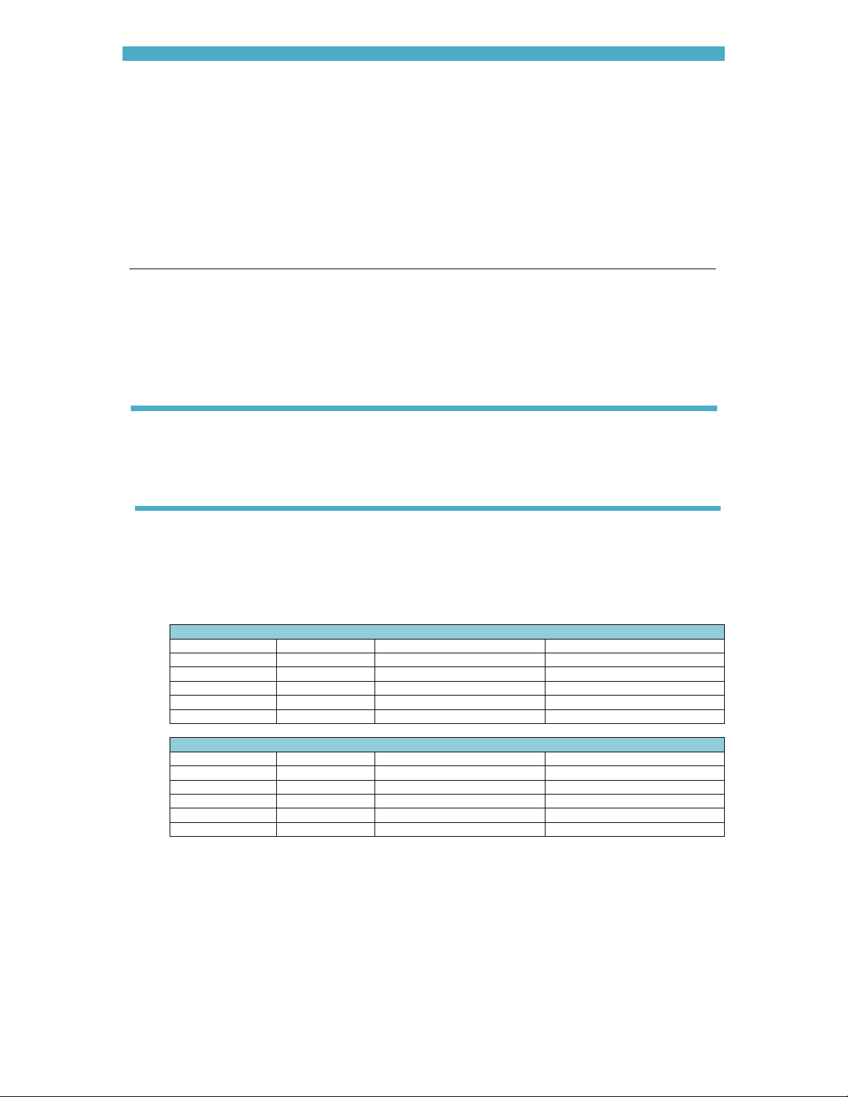
Outputs are rated 500 mA @24 V dc
AWS designations in parenthesis
1
inputs must be linked if not required
Pin I/O bit
1. 24 V (internal)
2. 24 V for I/O
3. 2 Stop (ES1)
4. 3 Transformer thermal (TT1)
5. 1 Weld on (NW1)
1
1
6. 0 V
Pin I/O bit
1. 24 V (24 VDC)
2. 0 Start (FS1)
3.
4.
5.
6. 9 P1 (BP1)
7. 10 P2 (BP2)
8. 11 P4 (BP4)
9. 12 P8 (BP8)
10. 13 P16 (BP16)
11. 14 P32 (BP32)
12. 8 Reset stepper (SR1)
13. 7 Reset counter/tip dress ack
14. 5 Retract (RT1)
15. 6 Reset fault (FR1)
nd
16. 4 2
stage (PS1)
17. 15 P64 (BP64)/Edit enable
WSP3 Power
1
Pin I/O bit
1. 15 AV1 (SV1)
2. 14 AV2 (SV2)
3. 13 AV3 (SV3)
4. 1 HAV (RV1)
5. Do not connect
6. 5 Counter
7. 6 Stepper
8. 7 Pre-warn
9. 12 AV4 (SV4)
10. 11 AV5 (SV5)
11. 10 AV6 (SV6)
12. 9 AV7 (SV7)
13. 8 AV8 (SV8)
14. 0 EOS (EH1)
15. 2 Fault (FT1)
16. 3 Ready
17. 4 Contactor (MC1)
18. 0 V (SVC)
Page 23
Section 4 Discrete I/O 23
MUX
1. Analog input #1 (0 to 10 V)
2. 0 V
3. Analog output #1 (0 to 10 V)
4. Ground
1. Analog input #2
2. Analog input #2
3. Toroid input
4. Toroid input
5. Ground
MODBUS-RTU
NetFlash
MODBUS-TCP/IP
1. Heartbeat
2. Ready
3. Sequence initiated
4. Weld current
5. Data receive COM0
6. Data send COM0
7. Data receive COM1
8. Data send COM1
9. Data receive COM2
10. Data send COM2
11. Data receive COM3
12. Data send COM3
Expansion
Page 24
Section 5 MODBUS I/O 24
MODBUS I/O
iPAK2 can be operated via MODBUS instead of using the discrete inputs and outputs.
Both MODBUS TCP/IP (Ethernet) and MODBUS RTU (RS485) protocols are supported.
Write the inputs using MODBUS function 16
Read the outputs using MODBUS function 3
MODBUS access types
Write inputs
Type Value Description
Function code UINT 16 Write multiple registers
Read offset UINT 0
Read length UINT 0
Write offset UINT 16#8000 (= 32768)
Write length UINT 2
Read outputs
Type Value Description
Function code UINT 3 Read holding registers
Read offset UINT 16#9000 (= 36864)
Read length UINT 24
Write offset UINT 0
Write length UINT 0
Page 25

Section 5 MODBUS I/O 25
MODBUS mapping (inputs to iPAK2)
Variable Channel Address Type Description
Write inputs %QW0 WORD ARRAY [0..1] Write multiple registers
Write inputs [0] %QW0 WORD WRITE 16#8000 (= 32768)
Start Bit 0 %QX0.0 BOOL
Weld on Bit 1 %QX0.1 BOOL
Stop Bit 2 %QX0.2 BOOL
Transformer thermal Bit 3 %QX0.3 BOOL
2nd stage Bit 4 %QX0.4 BOOL
Retract Bit 5 %QX0.5 BOOL
Reset fault Bit 6 %QX0.6 BOOL
Reset counter Bit 7 %QX0.7 BOOL
Reset stepper Bit 8 %QX1.0 BOOL
Reserved Bit 9 %QX1.1 BOOL
Reserved Bit 10 %QX1.2 BOOL
Reserved Bit 11 %QX1.3 BOOL
Reserved Bit 12 %QX1.4 BOOL
Reserved Bit 13 %QX1.5 BOOL
Reserved Bit 14 %QX1.6 BOOL
Reserved Bit 15 %QX1.7 BOOL
Write inputs [1] %QW2 WORD WRITE 16#8001 (= 32769)
P1 Bit 0 %QX2.0 BOOL
P2 Bit 1 %QX2.1 BOOL
P4 Bit 2 %QX2.2 BOOL
P8 Bit 3 %QX2.3 BOOL
P16 Bit 4 %QX2.4 BOOL
P32 Bit 5 %QX2.5 BOOL
P64 Bit 6 %QX2.6 BOOL
P128 Bit 7 %QX2.7 BOOL
Reserved Bit 8 %QX3.0 BOOL
Reserved Bit 9 %QX3.1 BOOL
Reserved Bit 10 %QX3.2 BOOL
Reserved Bit 11 %QX3.3 BOOL
Reserved Bit 12 %QX3.4 BOOL
Reserved Bit 13 %QX3.5 BOOL
Reserved Bit 14 %QX3.6 BOOL
Reserved Bit 15 %QX3.7 BOOL
Page 26

Section 5 MODBUS I/O 26
MODBUS mapping (outputs from iPAK2)
Variable Channel Address Type Description
Read outputs %IW0 WORD ARRAY [0..23] Read holding registers
Read outputs [0] %IW0 WORD READ 16#9000 (= 36864)
EOS Bit 0 %IX0.0 BOOL
HAV Bit 1 %IX0.1 BOOL
Fault Bit 2 %IX0.2 BOOL
Ready Bit 3 %IX0.3 BOOL
Contactor Bit 4 %IX0.4 BOOL
Counter Bit 5 %IX0.5 BOOL
Stepper Bit 6 %IX0.6 BOOL
Pre-warn Bit 7 %IX0.7 BOOL
AV8 Bit 8 %IX1.0 BOOL
AV7 Bit 9 %IX1.1 BOOL
AV6 Bit 10 %IX1.2 BOOL
AV5 Bit 11 %IX1.3 BOOL
AV4 Bit 12 %IX1.4 BOOL
AV3 Bit 13 %IX1.5 BOOL
AV2 Bit 14 %IX1.6 BOOL
AV1 Bit 15 %IX1.7 BOOL
Read outputs [1] %IW2 WORD READ 16#9001 (= 36865)
Start Bit 0 %IX2.0 BOOL
Weld on Bit 1 %IX2.1 BOOL
Stop Bit 2 %IX2.2 BOOL
Transformer thermal Bit 3 %IX2.3 BOOL
2nd stage Bit 4 %IX2.4 BOOL
Retract Bit 5 %IX2.5 BOOL
Reset fault Bit 6 %IX2.6 BOOL
Reset counter Bit 7 %IX2.7 BOOL
Reset stepper Bit 8 %IX3.0 BOOL
P1 Bit 9 %IX3.1 BOOL
P2 Bit 10 %IX3.2 BOOL
P4 Bit 11 %IX3.3 BOOL
P8 Bit 12 %IX3.4 BOOL
P16 Bit 13 %IX3.5 BOOL
P32 Bit 14 %IX3.6 BOOL
P64 Bit 15 %IX3.7 BOOL
Read outputs [2] %IW4 WORD READ 16#9002 (= 36866)
Start Bit 0 %IX4.0 BOOL
Weld on Bit 1 %IX4.1 BOOL
Stop Bit 2 %IX4.2 BOOL
Thermal Bit 3 %IX4.3 BOOL
2nd stage Bit 4 %IX4.4 BOOL
Retract Bit 5 %IX4.5 BOOL
Reset fault Bit 6 %IX4.6 BOOL
Reset counter Bit 7 %IX4.7 BOOL
Reset stepper Bit 8 %IX5.0 BOOL
P1 Bit 9 %IX5.1 BOOL
P2 Bit 10 %IX5.2 BOOL
P4 Bit 11 %IX5.3 BOOL
P8 Bit 12 %IX5.4 BOOL
P16 Bit 13 %IX5.5 BOOL
P32 Bit 14 %IX5.6 BOOL
P64 Bit 15 %IX5.7 BOOL
≘ %QX0.0
≘ %QX0.1
≘ %QX0.2
≘ %QX0.3
≘ %QX0.4
≘ %QX0.5
≘ %QX0.6
≘ %QX0.7
≘ %QX1.0
≘ discrete input P1
≘ discrete input P2
≘ discrete input P4
≘ discrete input P8
≘ discrete input P16
≘ discrete input P32
≘ discrete input P64
≘ discrete input Start
≘ discrete input Weld on
≘ discrete input Stop
≘ discrete input Thermal
≘ discrete input 2
≘ discrete input Retract
≘ discrete input Reset fault
≘ discrete input Reset counter
≘ discrete input Reset stepper
≘ discrete input P1
≘ discrete input P2
≘ discrete input P4
≘ discrete input P8
≘ discrete input P16
≘ discrete input P32
≘ discrete input P64
nd
stage
Page 27

Section 5 MODBUS I/O 27
Variable Channel Address Type Description
Analog input (mV) Read outputs [3] %IW6 WORD READ 16#9003 (= 36867)
Analog output (mV) Read outputs [4] %IW8 WORD READ 16#9004 (= 36868)
% pulse width Read outputs [5] %IW10 WORD READ 16#9005 (= 36869)
Reserved Read outputs [6] %IW12 WORD READ 16#9006 (= 36870)
Reserved Read outputs [7] %IW14 WORD READ 16#9007 (= 36871)
Status register 0 Read outputs [8] %IW16 WORD READ 16#9008 (= 36872)
Stop Bit 0 %IX16.0 BOOL Bit 0
Reserved Bit 1 %IX16.1 BOOL
Retract not ready Bit 2 %IX16.2 BOOL Bit 2
Inverter hot Bit 3 %IX16.3 BOOL Bit 3
Transformer hot Bit 4 %IX16.4 BOOL Bit 4
Pilot fault Bit 5 %IX16.5 BOOL Bit 5
Restart required Bit 6 %IX16.6 BOOL Bit 6
Headlock Bit 7 %IX16.7 BOOL Bit 7
Reserved Bit 8 %IX17.0 BOOL
Reserved Bit 9 %IX17.1 BOOL
Reserved Bit 10 %IX17.2 BOOL
Reserved Bit 11 %IX17.3 BOOL
Reserved Bit 12 %IX17.4 BOOL
Reserved Bit 13 %IX17.5 BOOL
Reserved Bit 14 %IX17.6 BOOL
Test mode Bit 15 %IX17.7 BOOL Bit 15
Status register 1 Read outputs [9] %IW18 WORD READ 16#9009 (= 36873)
Start on Bit 0 %IX18.0 BOOL Bit 16
Weld off Bit 1 %IX18.1 BOOL Bit 17
Program inhibited Bit 2 %IX18.2 BOOL Bit 18
Output fault Bit 3 %IX18.3 BOOL Bit 19
Reserved Bit 4 %IX18.4 BOOL
Too many links Bit 5 %IX18.5 BOOL Bit 21
Bad link Bit 6 %IX18.6 BOOL Bit 22
Maximum current Bit 7 %IX18.7 BOOL Bit 23
Toroid over range Bit 8 %IX19.0 BOOL Bit 24
CT over range Bit 9 %IX19.1 BOOL Bit 25
Maximum pulse width Bit 10 %IX19.2 BOOL Bit 26
Calibration error Bit 11 %IX19.3 BOOL Bit 27
Reserved Bit 12 %IX19.4 BOOL
Reserved Bit 13 %IX19.5 BOOL
Reserved Bit 14 %IX19.6 BOOL
Reserved Bit 15 %IX19.7 BOOL
Status register 2 Read outputs [10] %IW20 WORD READ 16#900A (= 36874)
Low force Bit 0 %IX20.0 BOOL Bit 32
High force Bit 1 %IX20.1 BOOL Bit 33
Low pre-current Bit 2 %IX20.2 BOOL Bit 34
High pre-current Bit 3 %IX20.3 BOOL Bit 35
Low main current Bit 4 %IX20.4 BOOL Bit 36
High main current Bit 5 %IX20.5 BOOL Bit 37
Low post-current Bit 6 %IX20.6 BOOL Bit 38
High post-current Bit 7 %IX20.7 BOOL Bit 39
No 2nd stage Bit 8 %IX21.0 BOOL Bit 40
No force Bit 9 %IX21.1 BOOL Bit 41
Reserved Bit 10 %IX21.2 BOOL
Reserved Bit 11 %IX21.3 BOOL
Reserved Bit 12 %IX21.4 BOOL
Reserved Bit 13 %IX21.5 BOOL
Reserved Bit 14 %IX21.6 BOOL
Reserved Bit 15 %IX21.7 BOOL
Page 28

Section 5 MODBUS I/O 28
Variable Channel Address Type Description
Status register 3 Read outputs [11] %IW22 WORD READ 16#900B (= 36875)
End of count 0 Bit 0 %IX22.0 BOOL Bit 48
End of count 1 Bit 1 %IX22.1 BOOL Bit 49
End of count 2 Bit 2 %IX22.2 BOOL Bit 50
End of count 3 Bit 3 %IX22.3 BOOL Bit 51
End of count 4 Bit 4 %IX22.4 BOOL Bit 52
End of count 5 Bit 5 %IX22.5 BOOL Bit 53
End of count 6 Bit 6 %IX22.6 BOOL Bit 54
End of count 7 Bit 7 %IX22.7 BOOL Bit 55
Reserved Bit 8 %IX23.0 BOOL
Reserved Bit 9 %IX23.1 BOOL
Reserved Bit 10 %IX23.2 BOOL
Reserved Bit 11 %IX23.3 BOOL
Reserved Bit 12 %IX23.4 BOOL
Reserved Bit 13 %IX23.5 BOOL
Reserved Bit 14 %IX23.6 BOOL
Reserved Bit 15 %IX23.7 BOOL
Status register 4 Read outputs [12] %IW24 WORD READ 16#900C (= 36876)
End of electrode 0 Bit 0 %IX24.0 BOOL Bit 64
End of electrode 1 Bit 1 %IX24.1 BOOL Bit 65
End of electrode 2 Bit 2 %IX24.2 BOOL Bit 66
End of electrode 3 Bit 3 %IX24.3 BOOL Bit 67
End of electrode 4 Bit 4 %IX24.4 BOOL Bit 68
End of electrode 5 Bit 5 %IX24.5 BOOL Bit 69
End of electrode 6 Bit 6 %IX24.6 BOOL Bit 70
End of electrode 7 Bit 7 %IX24.7 BOOL Bit 71
Reserved Bit 8 %IX25.0 BOOL
Reserved Bit 9 %IX25.1 BOOL
Reserved Bit 10 %IX25.2 BOOL
Reserved Bit 11 %IX25.3 BOOL
Reserved Bit 12 %IX25.4 BOOL
Reserved Bit 13 %IX25.5 BOOL
Reserved Bit 14 %IX25.6 BOOL
Reserved Bit 15 %IX25.7 BOOL
Status register 5 Read outputs [13] %IW26 WORD READ 16#900D (= 36877)
Tip dress 0 Bit 0 %IX26.0 BOOL Bit 80
Tip dress 1 Bit 1 %IX26.1 BOOL Bit 81
Tip dress 2 Bit 2 %IX26.2 BOOL Bit 82
Tip dress 3 Bit 3 %IX26.3 BOOL Bit 83
Tip dress 4 Bit 4 %IX26.4 BOOL Bit 84
Tip dress 5 Bit 5 %IX26.5 BOOL Bit 85
Tip dress 6 Bit 6 %IX26.6 BOOL Bit 86
Tip dress 7 Bit 7 %IX26.7 BOOL Bit 87
Reserved Bit 8 %IX27.0 BOOL
Reserved Bit 9 %IX27.1 BOOL
Reserved Bit 10 %IX27.2 BOOL
Reserved Bit 11 %IX27.3 BOOL
Reserved Bit 12 %IX27.4 BOOL
Reserved Bit 13 %IX27.5 BOOL
Reserved Bit 14 %IX27.6 BOOL
Reserved Bit 15 %IX27.7 BOOL
Page 29

Section 5 MODBUS I/O 29
Variable Channel Address Type Description
Status register 6 Read outputs [14] %IW28 WORD READ 16#900E (= 36878)
Prewarn 0 Bit 0 %IX28.0 BOOL Bit 96
Prewarn 1 Bit 1 %IX28.1 BOOL Bit 97
Prewarn 2 Bit 2 %IX28.2 BOOL Bit 98
Prewarn 3 Bit 3 %IX28.3 BOOL Bit 99
Prewarn 4 Bit 4 %IX28.4 BOOL Bit 100
Prewarn 5 Bit 5 %IX28.5 BOOL Bit 101
Prewarn 6 Bit 6 %IX28.6 BOOL Bit 102
Prewarn 7 Bit 7 %IX28.7 BOOL Bit 103
Reserved Bit 8 %IX29.0 BOOL
Reserved Bit 9 %IX29.1 BOOL
Reserved Bit 10 %IX29.2 BOOL
Reserved Bit 11 %IX29.3 BOOL
Reserved Bit 12 %IX29.4 BOOL
Reserved Bit 13 %IX29.5 BOOL
Reserved Bit 14 %IX29.6 BOOL
Reserved Bit 15 %IX29.7 BOOL
Status register 7 Read outputs [15] %IW30 WORD READ 16#900F (= 36879)
Bus fail Bit 0 %IX30.0 BOOL Bit 112
Short circuit Bit 1 %IX30.1 BOOL Bit 113
Fan failure Bit 2 %IX30.2 BOOL Bit 114
Inverter not ready Bit 3 %IX30.3 BOOL Bit 115
LMI config. error Bit 4 %IX30.4 BOOL Bit 116
LMI error Bit 5 %IX30.5 BOOL Bit 117
Duty cycle limit Bit 6 %IX30.6 BOOL Bit 118
Reserved Bit 7 %IX30.7 BOOL
Reserved Bit 8 %IX31.0 BOOL
Reserved Bit 9 %IX31.1 BOOL
Reserved Bit 10 %IX31.2 BOOL
Reserved Bit 11 %IX31.3 BOOL
Reserved Bit 12 %IX31.4 BOOL
Reserved Bit 13 %IX31.5 BOOL
Reserved Bit 14 %IX31.6 BOOL
Reserved Bit 15 %IX31.7 BOOL
Pre-heat current (A) Read outputs [16] %IW32 DWORD READ 16#9010 (= 36880)
Main current (A) Read outputs [18] %IW36 DWORD READ 16#9012 (= 36882)
Post-heat current (A) Read outputs [20] %IW40 DWORD READ 16#9014 (= 36884)
Program number Read outputs [22] %IW44 WORD READ 16#9016 (= 36886)
Force1 Read outputs [23] %IW46 WORD READ 16#9017 (= 36887)
1
value is multiplied by the scale factor (898.88 for kN or 4 for lbf
Page 30

Section 6 Weld control 30
Weld control
iPAK2 controls the weld sequence by using the I/O in conjunction with the welding parameters. The parameters
are stored in programs so that different materials and machine sequences can be used. There are 256 weld
programs.
Page 31
Section 6 Weld control 31
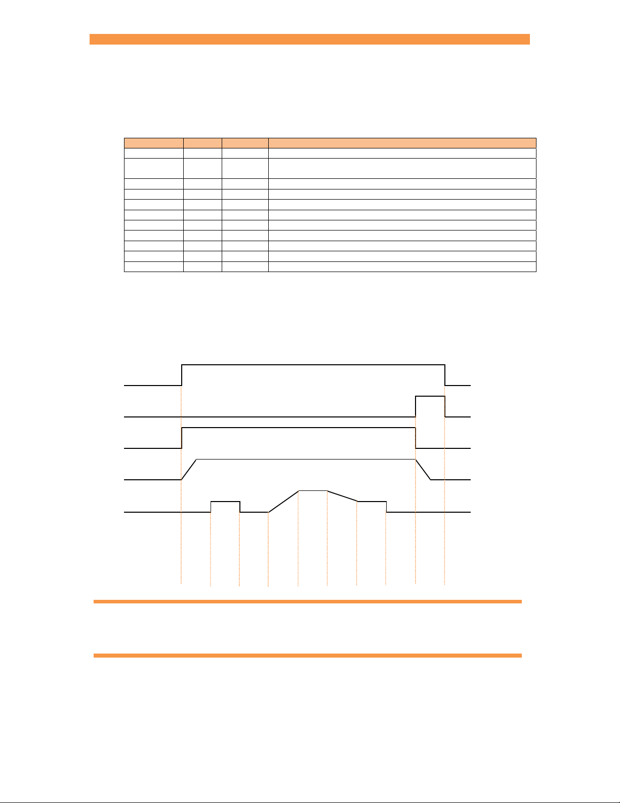
Spot sequence timing
The weld programs contain the following timing parameters.
Parameter Units Range Description
Presqueeze ms 0 - 1999 The time for the electrodes to close onto the work piece.
Squeeze ms 0 - 1999 The time between the initial application of the electrode force and
Pre-heat1 ms 0 - 1999 The pre-heat welding current is applied
Cool11 ms 0 - 1999 The material is allowed to cool with electrode force applied
Upslope ms 0 - 1999 Welding current is increased during this time
Main heat ms 0 - 1999 The main welding current is applied
Cool22 ms 0 - 1999 The material is allowed to cool with electrode force applied
Downslope ms 0 - 1999 Welding current is decreased during this time
Post-heat3 ms 0 - 1999 The post-heat welding current is applied
Hold ms 0 - 1999 Electrode force continues after the welding current has finished
Off4 ms 0 - 1999 Electrode force is released until the next sequence begins
1
Pre-heat program option must be enabled to use this feature
2
Pulsations program option must be greater than 1 to use this feature
3
Post-heat program option must be enabled to use this extended feature
the first application of welding current
The diagram shows how the parameters control the sequence. The Presqueeze and Cool2 intervals are
not shown.
Start input
EOS output
WAV output
Force
Current
Interval
Squeeze
Pre-heat
Cool1
Upslope
Main heat
Downslope
Post heat
Hold
Off
Upslope can be used on hard, irregular shaped, oxidized and aluminium materials
Downslope can be used to reduce marking and embrittlement
Page 32
Section 6 Weld control 32
p
p
t
p
t
p
p
t
p
p
p
t
p
t
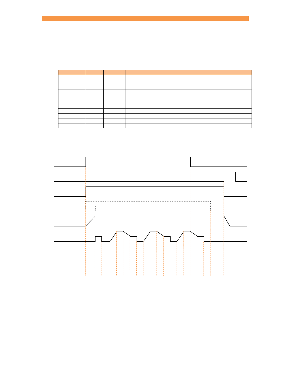
Seam sequence timing (extended feature)
The weld programs contain the following timing parameters. All parameters can be adjusted during the
sequence.
Parameter Units Range Description
Presqueeze ms 0 - 1999 The time for the electrodes to close onto the work piece.
Squeeze ms 0 - 1999 The time between the initial application of the electrode force and
Pre-heat1 ms 0 - 1999 The pre-heat welding current is applied
Cool11 ms 0 - 1999 The material is allowed to cool with electrode force applied
Upslope ms 0 - 1999 Welding current is increased during this time
Main heat ms 0 - 1999 The main welding current is applied
Downslope ms 0 - 1999 Welding current is decreased during this time
Post-heat2 ms 0 - 1999 The post-heat welding current is applied
Cool2 ms 0 - 1999 The material is allowed to cool with electrode force applied
Hold ms 0 - 1999 Electrode force continues after the welding current has finished
1
Pre-heat program option must be enabled to use this feature
2
Post-heat program option must be enabled to use this feature
The diagram shows how the parameters control the sequence. (Presqueeze not shown)
the first application of welding current
Start input1
EOS output
WAV output
Motor output2
Force
Current
e
e
slo
Interval
1
The intervals from Upslope to Cool2 repeat until the Start input is removed.
2
The operation of the motor output is determined by the 2nd stage test (Section 12 Configuration).
Squeeze
Pre-heat
Main hea
Cool1
U
Downslo
Post-hea
e
e
slo
Main hea
Cool2
U
Downslo
Post-heat
e
e
slo
Main hea
Cool2
U
Downslo
Post-hea
Cool2
Hold
Page 33
Section 6 Weld control 33
–
t
–
–
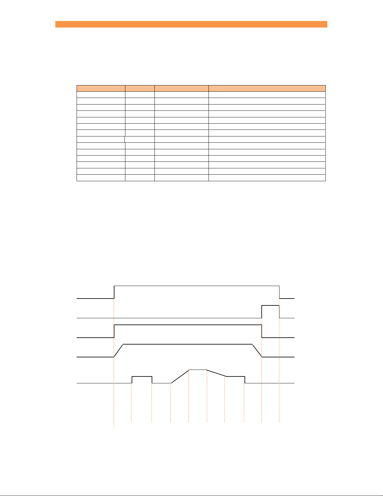
Spot current control
The weld programs contain the following current control parameters.
Parameter Units Range Description
Pre-mode1 P/W – CCu – CCC Operating mode of the Pre-heat interval
Pre-heat1 % 0.0 – 99.9 The % heat used during the Pre-heat interval
Pre-current1 kA 0 – 500 The current used during the Pre-heat interval
Pre-monitor1 yes/no The current can be tested between limits
Main mode P/W – CCu – CCC Operating mode of the Main heat interval
Main heat % 0.0 –99.9 The % heat used during the Main heat interval
Main current kA 0 – 500 The current used during the Main heat interval
Main monitor yes/no The current can be tested between limits
Post mode2 P/W
Post hea
2
% 0.0
Post current2 kA 0
Post monitor2 yes/no The current can be tested between limits
High limit % 0 - 99 Current high limit
Low limit % 0 - 99 Current low limit
1
Pre-heat program option must be enabled to use this feature
2
Post-heat program option must be enabled to use this extended feature
CCu –CCC Operating mode of the Post-heat interval
99.9 The % heat used during the Post-heat interval
500 The current used during the Post-heat interval
P/W (constant Pulse Width) mode. The current and heat parameters are independently adjustable. The
inverter pulse-width is fixed. The current parameter is used for monitoring only.
CCu (Constant Current uncalibrated) mode.
The current and heat parameters are independently
adjustable. The inverter uses a variable pulse-width to determine and regulate the actual current. The
current parameter is used for monitoring only.
CCC (Constant Current Calibrated) mode.
The current parameter is adjustable but the heat is
automatically determined by the iPAK2 from the calibration data.
The diagram shows how the parameters control the welding current. The Cool2 interval is not shown.
Start input
EOS output
WAV output
Force
Main heat/current
Pre-heat/current
Post-heat/current
Current
Interval
Squeeze
Pre-heat
Cool1
Upslope
Main heat
Downslope
Post-heat
Hold
Off
Page 34
Section 6 Weld control 34
–
–
–
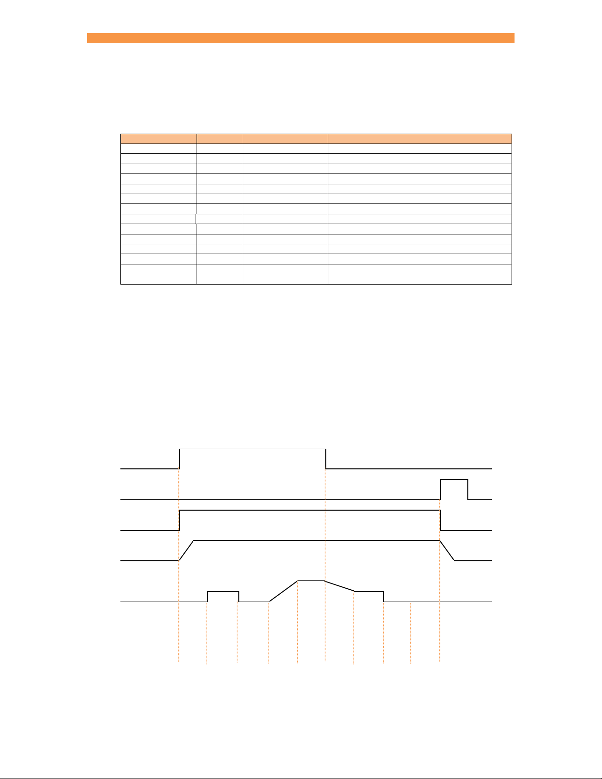
Seam current control (extended feature)
The weld programs contain the following current control parameters.
Parameter Units Range Description
Pre-mode1 P/W – CCu – CCC Operating mode of the Pre-heat interval
Pre-heat1 % 0.0 – 99.9 The % heat used during the Pre-heat interval
Pre-current1 kA 0 – 500 The current used during the Pre-heat interval
Pre-monitor1 yes/no The current can be tested between limits
Main mode P/W – CCu – CCC Operating mode of the Main heat interval
Main heat % 0.0 –99.9 The % heat used during the Main heat interval
Main current kA 0 – 500 The current used during the Main heat interval
Main monitor yes/no The current can be tested between limits
Post mode2 P/W
Post heat2 % 0.0
Post current2 kA 0
Post monitor2 yes/no The current can be tested between limits
High limit % 0 - 99 Current high limit
Low limit % 0 - 99 Current low limit
1
Pre-heat program option must be enabled to use this feature
2
Post-heat program option must be enabled to use this feature
CCu –CCC Operating mode of the Post-heat interval
99.9 The % heat used during the Post-heat interval
500 The current used during the Post-heat interval
P/W (constant Pulse Width) mode. The current and heat parameters are independently adjustable. The
inverter pulse-width is fixed. The current parameter is used for monitoring only.
CCu (Constant Current uncalibrated) mode.
The current and heat parameters are independently
adjustable. The inverter uses a variable pulse-width to determine and regulate the actual current. The
current parameter is used for monitoring only.
CCC (Constant Current Calibrated) mode.
The current parameter is adjustable but the heat is
automatically determined by the iPAK2 from the calibration data.
The diagram shows how the parameters control the welding current.
Start input
EOS output
WAV output
Force
Main heat/current
Pre-heat/current
Post-heat/current
Current
Interval
Squeeze
Pre-heat
Cool1
Upslope
Main heat
Downslope
Post-heat
Cool2
Hold
Page 35
Section 6 Weld control 35
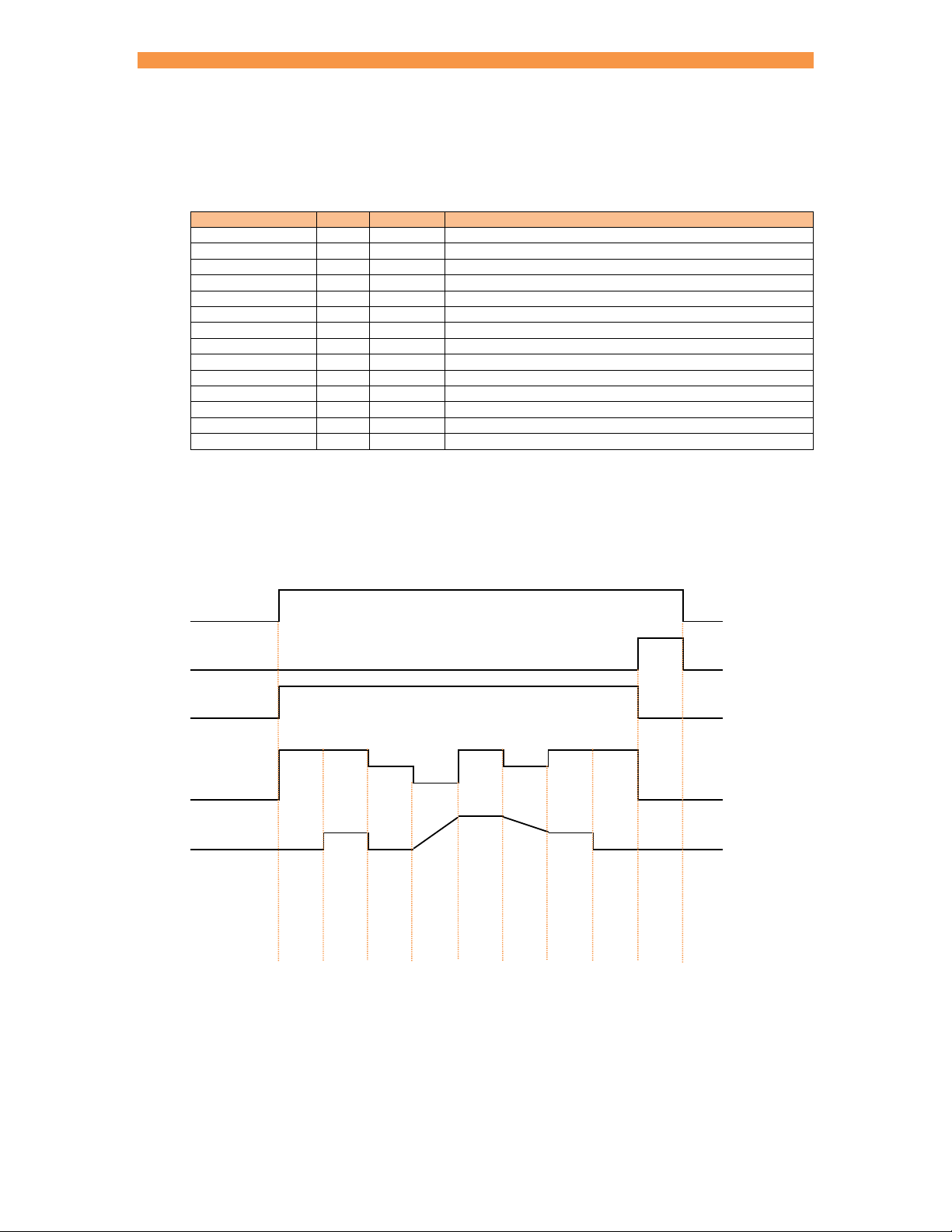
Force control
The weld programs contain the following force control parameters.
Parameter Units Range Description
Squeeze1 kN/lbf variable Force used from the start of the Squeeze interval
Pre-heat1 kN/lbf variable Force used from the start the Pre-heat interval
Cool11 kN/lbf variable Force used from the start the Cool1 interval
Upslope1 kN/lbf variable Force used from the start the Upslope interval
Main heat kN/lbf variable Force used from the start of the Main heat interval
Cool2 kN/lbf variable Force used from the start of the Cool2 interval
Downslope1 kN/lbf variable Force used from the start of the Downslope interval
Post-heat1 kN/lbf variable Force used from the start the Post-heat interval
Hold1 kN/lbf variable Force used from the start the Hold interval
1,2
Off
kN/lbf variable Force used from the start the Off interval
Wait for force3 yes/no Wait until the applied force has been reached
Test force yes/no Test the applied force at the end of the Main interval
High limit % 0 - 99 Force high limit
Low limit % 0 - 99 Force low limit
1
Force profile program option must be enabled to use this extended feature. If the force profile option is
disabled the Main heat force is used for the duration of the weld.
2
Repeat mode program option must be enabled to use this feature.
3
Occurs at the same time as 2nd stage. If Wait for force is required without 2nd stage, select 2nd stage
Before or After Squeeze (Section 12 Configuration) and permanently assert the 2
nd
stage input.
The diagram shows how iPAK2 can control the welding force. The Cool2 interval is not shown.
Start input
EOS output
WAV output
Force
Current
Interval
Squeeze
Pre-heat
Cool1
Upslope
Main heat
Downslope
Post-heat
Hold
Off
Page 36
Section 6 Weld control 36
Valves
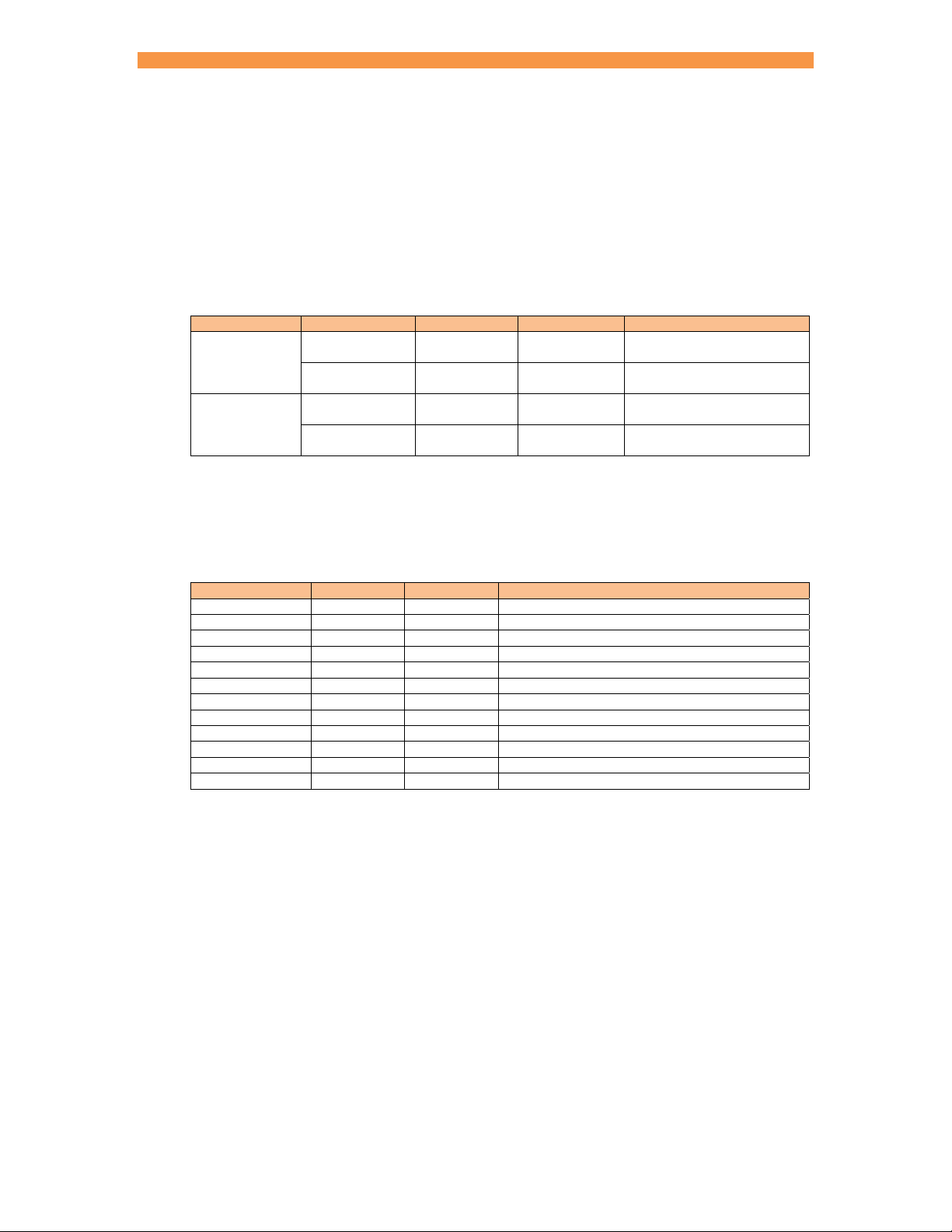
iPAK2 controls have eight digital outputs or valves (AV1 – AV8) that can be operated independently
during a weld sequence. The valves are categorised as WAV, motor
A WAV valve turns on at start of sequence and turns off at the end of the Hold interval.
The operation of a motor valve is determined by the 2
An AUX valve may be programmed to come on during any interval of the weld sequence,
including the Off time in repeat mode.
Mode Configuration WAV function Motor function Description
Single electrode AV1 n/a
spot
Multi-electrode1 AV1 – AV8 n/a
Single electrode AV1 AV2
seam1
Multi-electrode1 AV1 – AV8 AV1 – AV8
1
Extended feature
Valves not being used for the WAV or motor function may be used as AUX valves. WAV/motor settings
always override any corresponding AUX settings.
The weld programs contain the following valve control parameters.
Parameter Units Range Description
WAV AV1 –AV8 WAV output
Motor1 AV1 – AV8 Motor output
Squeeze AV1 – AV8 on/off Valve states during the Squeeze interval
Pre-heat AV1 – AV8 on/off Valve states during the Pre-heat interval
Cool1 AV1 – AV8 on/off Valve states during the Cool1 interval
Upslope AV1 – AV8 on/off Valve states during the Upslope interval
Main heat AV1 – AV8 on/off Valve states during the Main heat interval
Cool2 AV1 – AV8 on/off Valve states during the Cool2 interval
Downslope AV1 – AV8 on/off Valve states during the Downslope interval
Post-heat AV1 – AV8 on/off Valve states during the Post-heat interval
Hold AV1 – AV8 on/off Valve states during the Hold interval
Off2 AV1 – AV8 on/off Valve states during the Off interval
1
Seam mode only.
2
Repeat mode program option must be enabled to use this feature.
1
or AUX valves.
nd
stage test (Section 12 Configuration).
AV1 is automatically
selected
Any combination of AV1 to
AV8 may be selected
AV1 and AV2 are
automatically selected
Any combination of AV1 to
AV8 may be selected
Page 37
Section 6 Weld control 37
Options
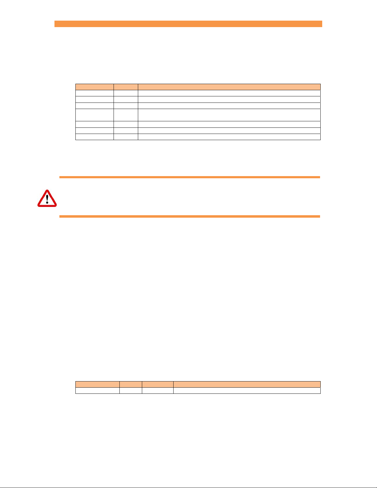
Each weld program has a number of optional features.
Parameter Range Description
Pre-heat yes/no Enables or disables the Pre-heat parameters
Post-heat yes/no Enables or disables the Post-heat parameters
Pulsations 1 - 99 The number of times the Main heat – Cool2 interval is repeated
Link yes/no The next welding program will be started automatically if the input signals
Repeat yes/no The welding program will be repeated if the input signals are maintained
Force profile yes/no Use multiple force values during the weld
Inhibit yes/no An inhibited program will not run
1
If an inhibited program is not linked then attempting to run it will produce the error message. If the
program is linked, then the program will be skipped and the next linked program will run. This feature
may be used to temporarily disable a program in a cascade.
Pulsations can be used to temper the material, control nugget growth and reduce electrode wear.
The Start signal must be maintained for the full duration of the sequence if pulsations are set to 10 or
more, otherwise the sequence will terminate after 10 pulses.
are maintained
1
Program selection
The program that will be used for welding can be selected in one of two ways
Section 12 Configuration: by using the Program Select inputs (external)
Section 13 Programming: by using the Use Program parameter (internal)
If the external method is used, inputs P1 – P64 correspond to the binary value of the program that will
be used. If the internal method is used, the Use Program parameter determines the weld program that
will be used. The program number can be changed during the weld sequence.
Multi-electrode operation (extended feature)
Each welding program can be assigned an electrode.
Parameter Units Range Description
Electrode 0 - 7 The electrode number
When a program is used, iPAK2 will automatically trigger the correct transformer by referencing the
electrode/transformer assignment as described below. In addition, the electrode number is also used to
access the appropriate stepper, counter and calibration information
Page 38

Section 7 Electrode management 38
Electrode management
Electrode management is provided via a combination of stepper and counter functions.
The stepper provides a means of gradually increasing the current to compensate for electrode wear. The counter
counts the number of welds that the electrode has done and allows the electrode to be dressed a number of
times before it is replaced. The extended features provide eight steppers and counters that can be assigned to up
to eight transformers.
Page 39
Section 7 Electrode management 39
Steppers
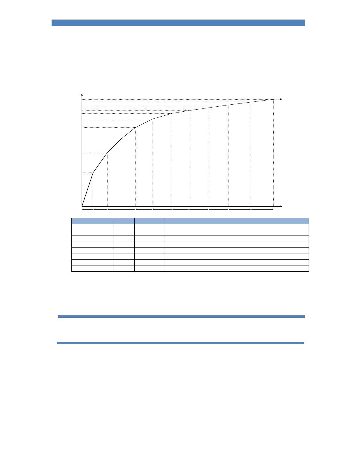
A stepper is programmed by means of a curve which will provide values of heat and current increments
related to the number of spots done. The curve is defined by a set of 10 points.
Current or Heat
dH9/dI
dH4/dI
dH3/dI
dH2/dI
9
4
3
2
dH1/dI
1
dH0/dI
0
Spots
Step 0 Step 1 Step 2 Step 3 Step 4 Step 5 Step 6 Step 7 Step 8 Step 9
Parameter Units Range Description
Step 0 - 9 The step number
Spots welds 0 - 9999 The number of welds in the step
+Heat % 0.0 - 50.0 The increase in heat during the step
+Current % 0.0 - 50.0 The increase in current during the step
Preset 1 - 5 Apply predefined values to the stepper curve
Enable stepper yes/no Enables or disables the stepper
Stop at end yes/no The iPAK2 can inhibit welding at the end of the last step
Spots done welds 0 - 99999 The number of welds that have been done since the last reset
P/W and CCu modes will make use of both the +Heat and +Current parameters. CCC mode uses only
the +Current parameters.
The Stepper output is active at the end of the last step. The Prewarn output is active during the last
step.
To get started enter the values for Step 9 then select a Preset to load the intermediate values
Page 40
Section 7 Electrode management 40
Counters
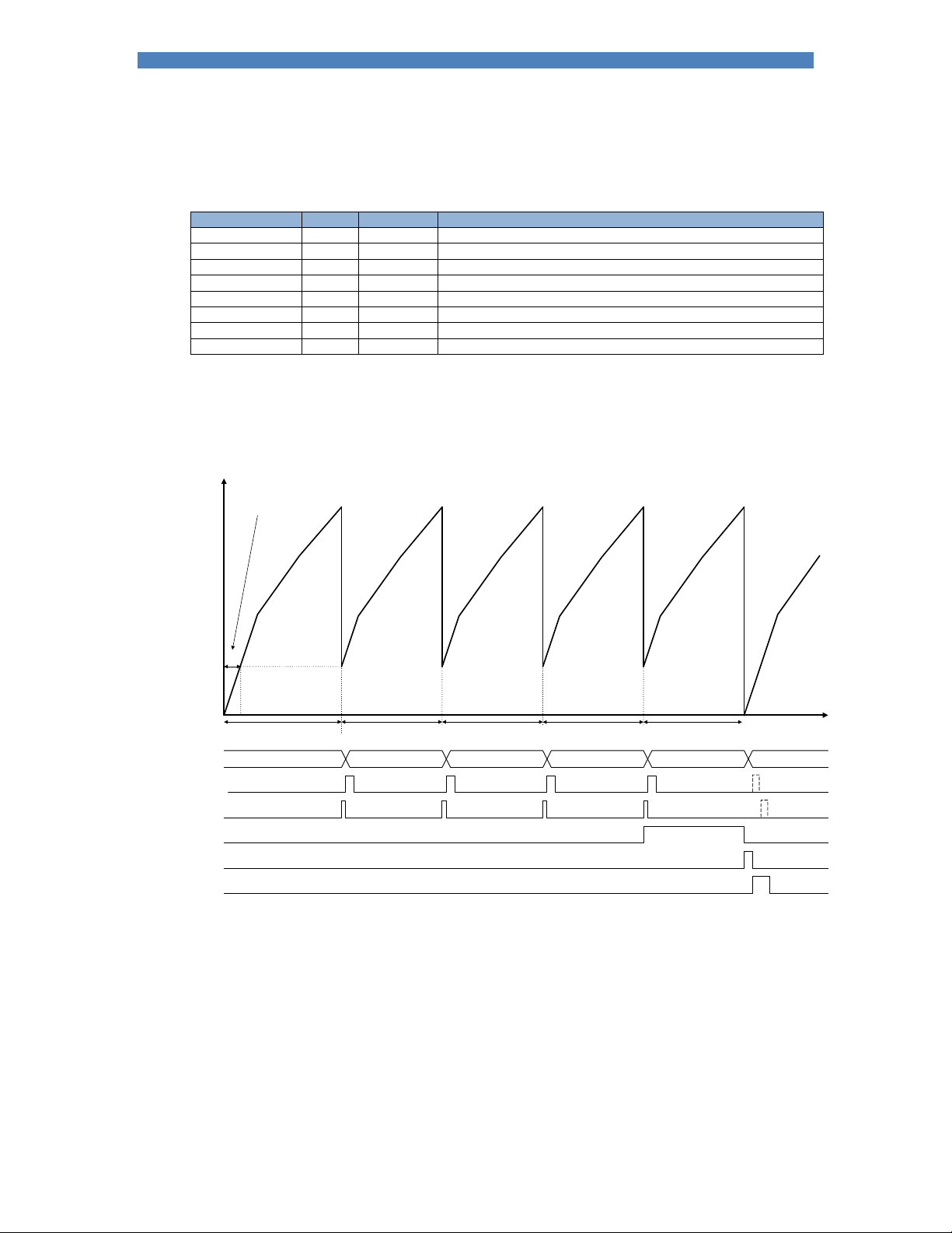
A counter is programmed by entering values related to the electrode maintenance and lifetime.
Parameter Units Range Description
Enable counter yes/no Enables or disables the counter
Count welds 0 - 9999 The number of welds that have been done since the last reset
End count welds 0 - 99999 The maximum number of welds that can be done
Stop at end yes/no The iPAK2 can inhibit welding until the counter is reset
Enable tip dress yes/no Enables or disables the tip dressing feature
Dressings done 0 - 9999 The number of times the electrodes have been dressed
Max dressings 0 - 9999 The maximum number of times the electrodes can be dressed
Reset to welds 0 - 9999 The weld count following a tip dress operation
If tip dressing is enabled the iPAK2 will activate the Tip Dress Request output when the Count value is
reached.
Current
or Heat
@reset,stepper=n
Tip-dress Tip-dress Tip-dress Tip-dress Replace electrodes
max. dressings=4
n
Count up to
Dressings done
012340
Reset counter input
Tip-dress (Counter)
output
Pre-warn output
End of stepper output
Reset stepper input
Count up to-n
Count up to-n Count up to-n
Spots
Count up to-n
See note 1
Page 41
Section 7 Electrode management 41
Current calibration
Current is measured by one of two methods:
1. Primary current is measured by the iPAK2 built-in CT.
2. Secondary current can be measured via an externally connected Toroid (spot weld modes
only).
The method is selected by the Configuration parameter Measure (Section 12 Configuration).
Maximum Primary Current
The inverter chassis has a maximum output current specification dependant on the inverter size. The
iPAK2 detects this value on power-up and sets it as an absolute maximum. The output current can be
set below this maximum value. It is important to do this before attempting any of the following calibration
procedures (Section 12 Configuration).
Current measurement by built-in CT
In order to display secondary current, there are two methods provided for conversion:
1. Turns ratio: The turns ratio may be obtained from the welding transformer data. The displayed
secondary current will be the measured primary current multiplied by this value. This method
does not allow for losses in the transformer but will provide reasonable accuracy.
2. Points 1&2: This is the more accurate method and also calibrates the iPAK2 to match an
external current meter. Two test welds establish the relationship between primary current (as
measured by the CT) and secondary current measured using the external meter as follows:
Initially, select the turns-ratio method and set the turn ratio to 1:1 so that the iPAK2
measures and displays primary current.
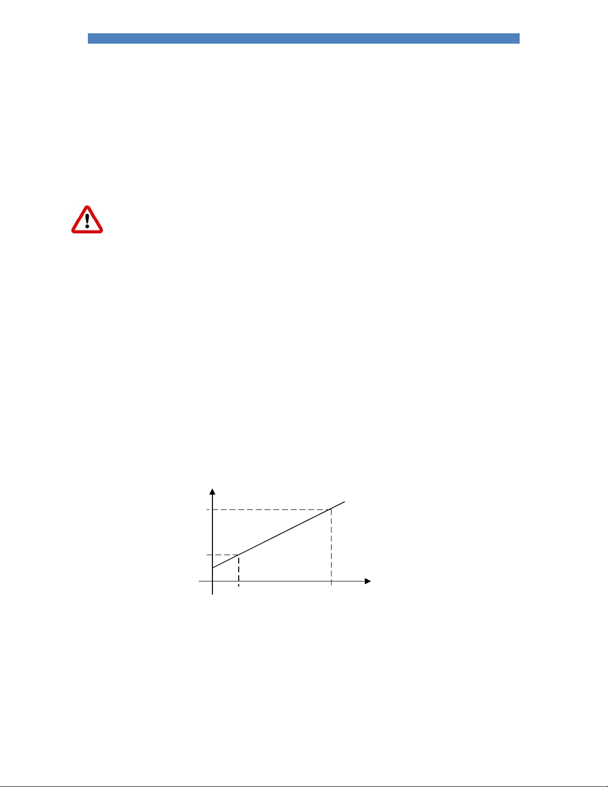
Produce a short circuit weld at a low heat in CCu mode and note the primary current (Ip1)
from the iPAK2 and the corresponding secondary current (Is1) using an external weld
current meter.
Repeat the short circuit weld at a higher heat and note again the primary current (Ip2) and
secondary current (Is2).
Now select the Points 1&2 method and enter the four measurements (Ip1, Is1 and Ip2,
Is2).
The iPAK2 uses the characteristic to calculate the secondary current from the measured primary
current.
I
s
I
s2
I
s1
I
I
p1
I
p2
p
Page 42
Section 7 Electrode management 42
Current measurement by external toroid (spot weld only)
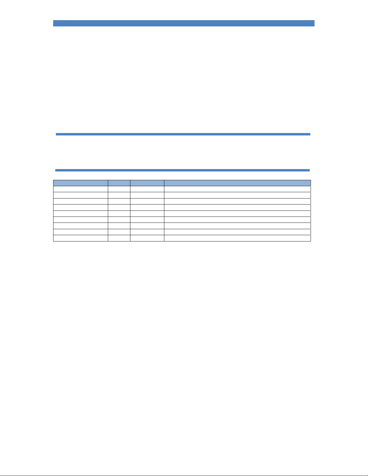
A toroid (Rogowski coil) is connected around the welding transformer secondary. Most such coils have a
nominal output of 150 mV/kA. The iPAK2 provides a sensitivity parameter which may be adjusted to
provide for absolute matching with an external current meter.
At the nominal 150 mV/kA, iPAK2 will handle signals corresponding to about 50 kA. If the current is
expected to exceed 50 kA then it is necessary to use an attenuator device such as a TAM/1 between
the toroid and iPAK2. The attenuator will have options for x1, x2, x3, x4 etc. The factor selected should
be entered into the iPAK2 so that it is able to calculate the actual current from the (attenuated)
measured current.
In multi-electrode or multi-transformer (cascade) systems it may be difficult to arrange toroids for
multiple secondary circuits. The toroids need to be switched in and out of circuit at the appropriate
moment in the sequence or errors will occur. In these circumstances use the CT measurement method.
The CT method has the advantage of not requiring an external toroid.
Parameter Units Range Description
Max. primary current A 0 - max Limits maximum output
Conversion method points/ratio Method used to convert primary current to secondary current
Turns ratio 1 - 999 The turns ratio of the welding transformer
Point 1 (primary) kA 0 - 32.0 The measured value of primary current at a low heat (Ip1)
Point 1 (secondary) kA 0 - 500.0 The measured value of secondary current at a low heat (Is1)
Point 2 (primary) kA 0 - 32.0 The measured value of primary current at a high heat (Ip2)
Point 2 (secondary) kA 0 - 500.0 The measured value of secondary current at a high heat (Is2)
Toroid mV/kA 100 - 60000 The sensitivity of the toroid
Toroid factor 1 - 10 The ratio of the external attenuator (1 if no attenuator fitted)
Page 43
Section 7 Electrode management 43
CCC calibration
The current must be calibrated before carrying out the following procedure.
When operating in CCu mode the inverter uses the Heat parameter to determine the output current. In
order to be able to control the output current directly in amps it is necessary to establish the relationship
between Heat and Current as follows:
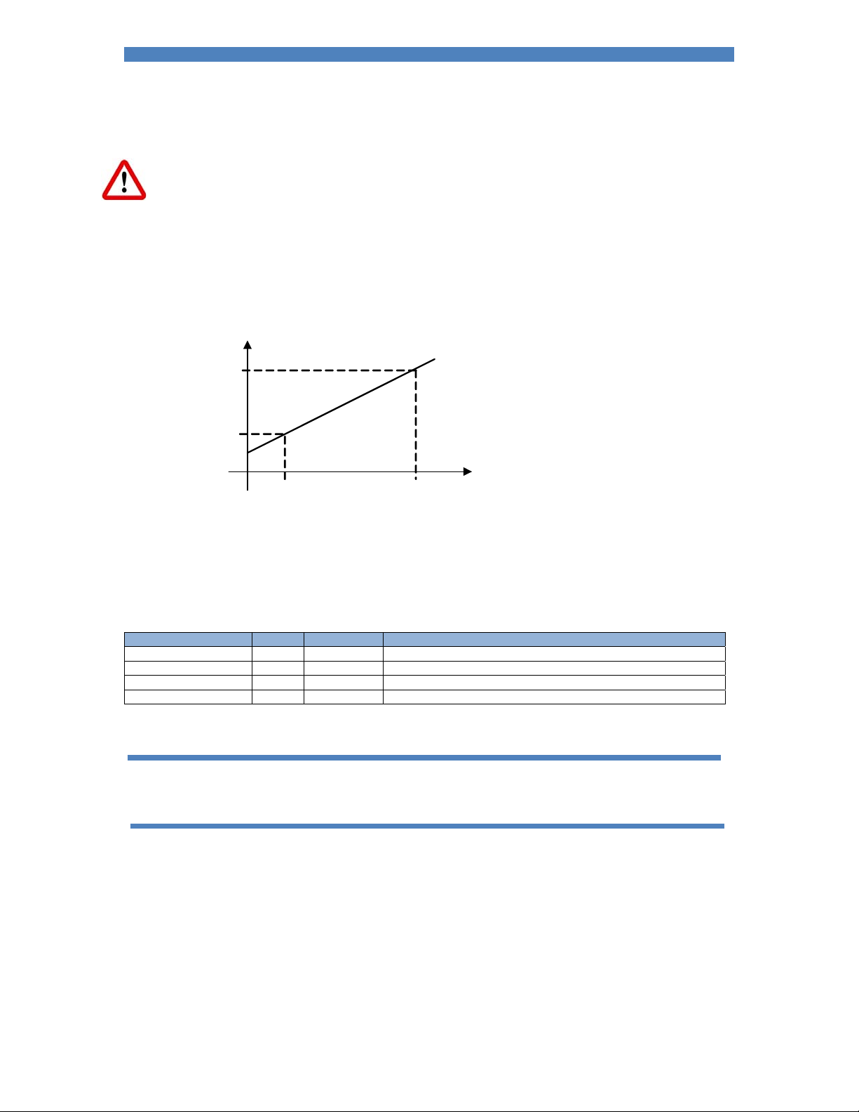
Produce a short circuit weld at a low heat in CCu mode and note the heat setting (H1) from the
iPAK2 and the corresponding measured current (I1).
Repeat the short circuit weld at a higher heat and note Heat (H2) and Current (I2).
Enter these values as the ‘Points 1&2’ parameters in CCC calibration.
Current
I
2
I
1
H
1
The iPAK2 will use these values to determine the relationship between Heat and Current. CCC mode
can now be selected in the welding schedules and required current programmed directly in amps. The
Heat parameter is no longer required.
This calibration also assists the iPAK to produce a rapid rise-time to the desired current without causing
any significant transient conditions.
Parameter Units Range Description
Point 1 (heat) % 0 – 99.9 The set value of low heat (H1)
Point 1 (current) kA 0 - 500.0 The measured value of current at a low heat (I1)
Point 2 (heat) % 0 – 99.9 The set value of high heat (H2)
Point 2 (current) kA 0 - 500.0 The measured value of current at a high heat (I2)
In multi-electrode systems there are separate calibration files for each gun. Each electrode must be
calibrated before being used.
H
Heat
2
Page 44
Section 7 Electrode management 44
Force calibration
The analog input and analog output can be used for force control in terms of kN or lbf when they have
been calibrated.
Parameter Units Range Description
OUT Point 1 mV 0 - 10000 Analog output (point 1)
OUT Point 1 kN/lbf Measured output force (point 1)
OUT Point 2 mV 0 - 10000 Analog output (point 2)
OUT Point 2 kN/lbf Measured output force (point 2)
IN Point 1 mV 0 - 10000 Analog input (point 1)
IN Point 1 kN/lbf Measured input force (point 1)
IN Point 2 mV 0 - 10000 Analog input (point 2)
IN Point 2 kN/lbf Measured input force (point 2)
The relationship between the analog input and output and the electrode force can be determined by
measuring the values at two points. The values define a linear relationship between mV and kN/lbf.
The force can be calibrated for each electrode.
Page 45
Section 7 Electrode management 45
Multi-electrode operation (extended feature)
Multi-electrode operation allows each welding program to be triggered independently and also allows
the assignment of an electrode to a transformer.
Parameter Units Range Description
Electrode 0 - 7 The electrode number
Transformer 0 - 7 The transformer that the electrode is connected to
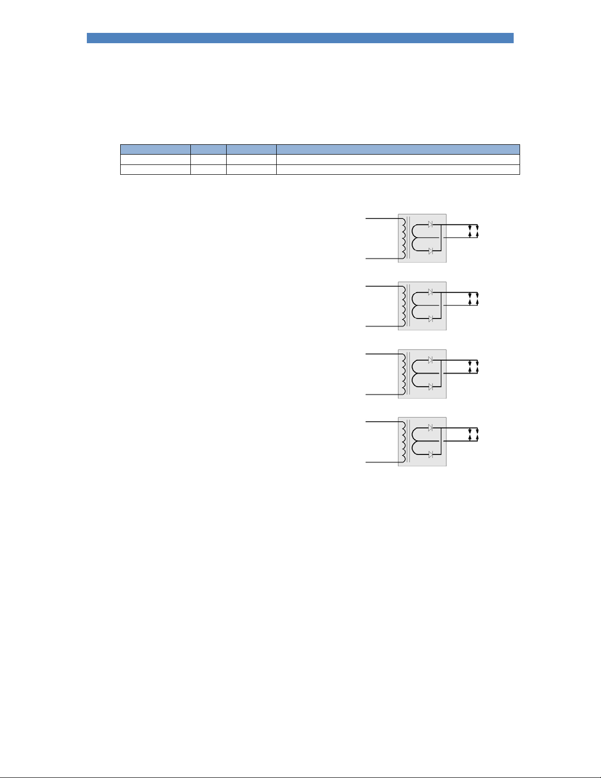
The diagram shows how the electrodes can be assigned to transformers
Electrodes 0 and 1 are assigned to transformer 0
Electrodes 2 and 3 are assigned to transformer 1
Electrodes 4 and 5 are assigned to transformer 2
Electrodes 6 and 7 are assigned to transformer 3
The electrodes are assigned to weld programs in the same way.
T0
T1
T2
T3
E0
E1
E2
E3
E4
E5
E6
E7
Page 46

Section 8 Status 46
Status information
iPAK2 reports a number of conditions to assist with diagnostics, quality control and maintenance. Each condition
corresponds to a code which is accessible via MODBUS.
Co
Condition Action
de
0 Normal
1 Stop Check the Stop input
2 Sync. error Check 27 V ac sync signal and/or the Frequency parameter in Configuration
3 Retract not ready Operate the Retract input
4 Inverter hot Check inverter cooling
5 Transformer hot Check weld transformer cooling
6 Pilot fault Safety relay fault. Do not use the iPAK2 and return it for service.
7 Restart required Restart the iPAK2
8 Headlocked The welding head is locked because of a fault condition
9 Toroid short circuit Connection to Toroid (secondary feedback coil) is short-circuit
10 Toroid open circuit Connection to Toroid (secondary feedback coil) is open-circuit
11 Reserved
12 Reserved
13 Reserved
14 Reserved
15 Reserved
16 Test mode For service use only
17 Start on The Start input is on following a weld sequence or stop/power-up condition
18 Weld off Check the Weld On input
19 Program inhibited The selected weld program is inhibited
20 Output fault One or more outputs have failed
21 Reserved
22 Too many links Too many weld programs are linked together
23 Bad link A link has been made to a weld program that cannot be used
24 Max. current Check secondary circuit. Reduce heat/current.
25 Toroid overrange Reduce current or use an external signal attenuator
26 CT overrange Check calibration parameters
27 Max. pulse width Check secondary circuit. Reduce heat/current.
28 Calibration error Check parameters in calibration program
29 Reserved
30 Reserved
31 Reserved
32 Reserved
33 Low force Check the analog input and output circuits and/or adjust force parameters
34 High force Check the analog input and output circuits and/or adjust force parameters
35 Low pre-current Check toroid feedback and/or adjust Pre-heat parameters
36 High pre-current Check toroid feedback and/or adjust Pre-heat parameters
37 Low main current Check toroid feedback and/or adjust Main heat parameters
38 High main current Check toroid feedback and/or adjust Main heat parameters
39 Low post-current Check toroid feedback and/or adjust Post-heat parameters
40 High post-current Check toroid feedback and/or adjust Post-heat parameters
41 No 2nd stage Check the 2ndStage input
Page 47

Section 8 Status 47
42 No force Check analog input circuit
43 Reserved
44 Reserved
45 Reserved
46 Reserved
47 Reserved
48 Reserved
49 End of count 0 Reset counter 0
50 End of count 1 Reset counter 1
51 End of count 2 Reset counter 2
52 End of count 3 Reset counter 3
53 End of count 4 Reset counter 4
54 End of count 5 Reset counter 5
55 End of count 6 Reset counter 6
56 End of count 7 Reset counter 8
57 Reserved
58 Reserved
59 Reserved
60 Reserved
61 Reserved
62 Reserved
63 Reserved
64 Reserved
65 End of electrode 0 Reset stepper 0
66 End of electrode 1 Reset stepper 1
67 End of electrode 2 Reset stepper 2
68 End of electrode 3 Reset stepper 3
69 End of electrode 4 Reset stepper 4
70 End of electrode 5 Reset stepper 5
71 End of electrode 6 Reset stepper 6
72 End of electrode 7 Reset stepper 7
73 Reserved
74 Reserved
75 Reserved
76 Reserved
77 Reserved
78 Reserved
79 Reserved
80 Reserved
81 Tip dress 0 Dress the electrodes and then reset counter 0
82 Tip dress 1 Dress the electrodes and then reset counter 1
83 Tip dress 2 Dress the electrodes and then reset counter 2
84 Tip dress 3 Dress the electrodes and then reset counter 3
85 Tip dress 4 Dress the electrodes and then reset counter 4
86 Tip dress 5 Dress the electrodes and then reset counter 5
87 Tip dress 6 Dress the electrodes and then reset counter 6
88 Tip dress 7 Dress the electrodes and then reset counter 7
89 Reserved
90 Reserved
91 Reserved
92 Reserved
93 Reserved
94 Reserved
95 Reserved
96 Reserved
97 Prewarn 0 Stepper 0 has completed its 9th step
98 Prewarn 1 Stepper 1 has completed its 9th step
99 Prewarn 2 Stepper 2 has completed its 9th step
100 Prewarn 3 Stepper 3 has completed its 9th step
101 Prewarn 4 Stepper 4 has completed its 9th step
102 Prewarn 5 Stepper 5 has completed its 9th step
103 Prewarn 6 Stepper 6 has completed its 9th step
104 Prewarn 7 Stepper 7 has completed its 9th step
105 Reserved
Page 48
Section 8 Status 48
106 Reserved
107 Reserved
108 Reserved
109 Reserved
110 Reserved
111 Reserved
112 Reserved
113 DC bus failure Check mains supply to inverter
114 Short circuit Check cables from inverter to welding transformer. Check transformer.
115 Fan fail Check inverter fans
116 Inverter not ready Check control connections to inverter
117 LMI config. error Check connections on LMI modules
118 LMI error Check indicator panel on LMI modules
119 Duty cycle limit The allowable duty cycle is being exceeded. Reduce time, current or rate of operation.
120 Reserved
121 Reserved
122 Reserved
123 Reserved
124 Reserved
125 Reserved
126 Reserved
127 Reserved
128 Reserved
Page 49
Section 9 History log 49
–
–
History log
iPAK2 stores the results of the last 6000 spot welds in a history log. Each record contains the following
information:
Parameter Units Range Description
Time and date The time and date when the entry was recorded
Program 0 - 255 The weld program used
Pre-current kA 0 – 500 The current recorded during the Pre-heat interval
Main current kA 0
Post-current kA 0
Force kN/lbf Variable The force recorded during the weld
500 The current recorded during the Main heat interval
500 The current recorded during the Post-heat interval
The log can be viewed or reset as required.
Page 50
Section 10 Multiwelding 50
Multiwelding (extended feature)
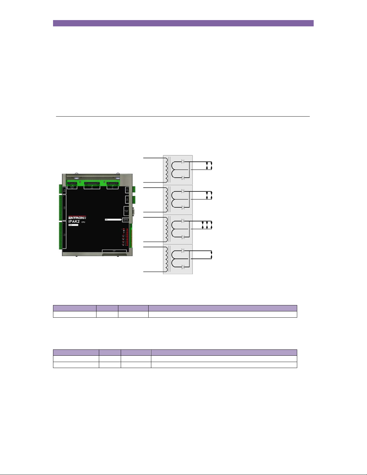
iPAK2 allows up to four transformers to be directly connected or up to eight when used with a decoder.
Up to 8 electrodes can be assigned
to the welding transformers
The electrode number is determined by the weld program:
Parameter Units Range Description
Electrode 0 - 7 The electrode number
The weld programs can be linked together.
The electrode is assigned to a transformer:
Parameter Units Range Description
Electrode 0 - 7 The electrode number
Transformer 0 - 7 The transformer that the electrode is connected to
Page 51
Section 10 Multiwelding 51
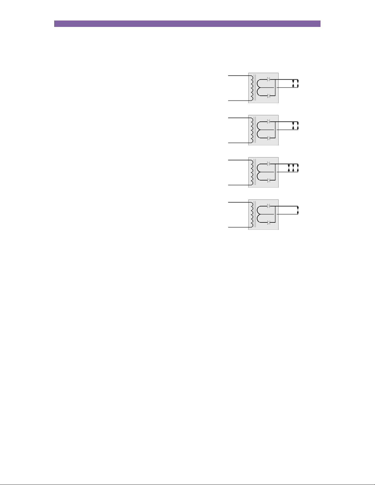
The diagram shows how the electrodes can be assigned to transformers
T0
Electrodes 0 and 1 are assigned to transformer 0
T1
Electrodes 2 and 3 are assigned to transformer 1
T2
Electrodes 4, 5 and 6 are assigned to transformer 2
T3
Electrode 7 is assigned to transformer 3
E0
E1
E2
E3
E4 E6
E5
E7
There are two methods available for multiwelding.
Multi-gun operation allows each welding program to be triggered independently but allows for selection
of a transformer and electrode.
Multi-gun cascade operation allows up to sixteen welding programs to be linked together and triggered
from a single start command. The programs then ripple through with minimal time between them,
selecting transformers and electrodes on the fly. The linked programs are known as a cascade.
Page 52
Section 10 Multiwelding 52
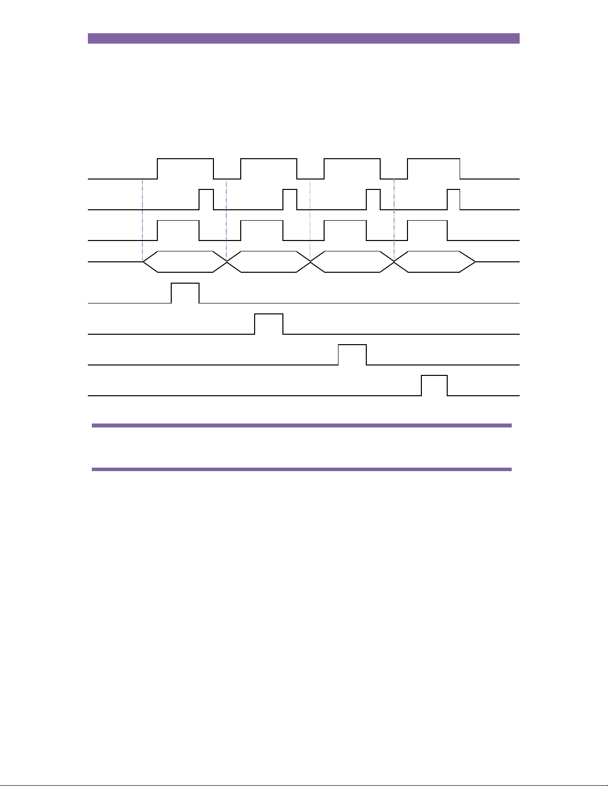
Multi-gun operation
Each welding program is started independently but different electrodes and transformers can be
selected.
Start input
EOS output
WAV output
Program
select
Current
(transformer 0)
Current
(transformer 1)
Current
(transformer 2)
Current
(transformer 3)
The WAV output can be a separate output for each program
Page 53
Section 10 Multiwelding 53
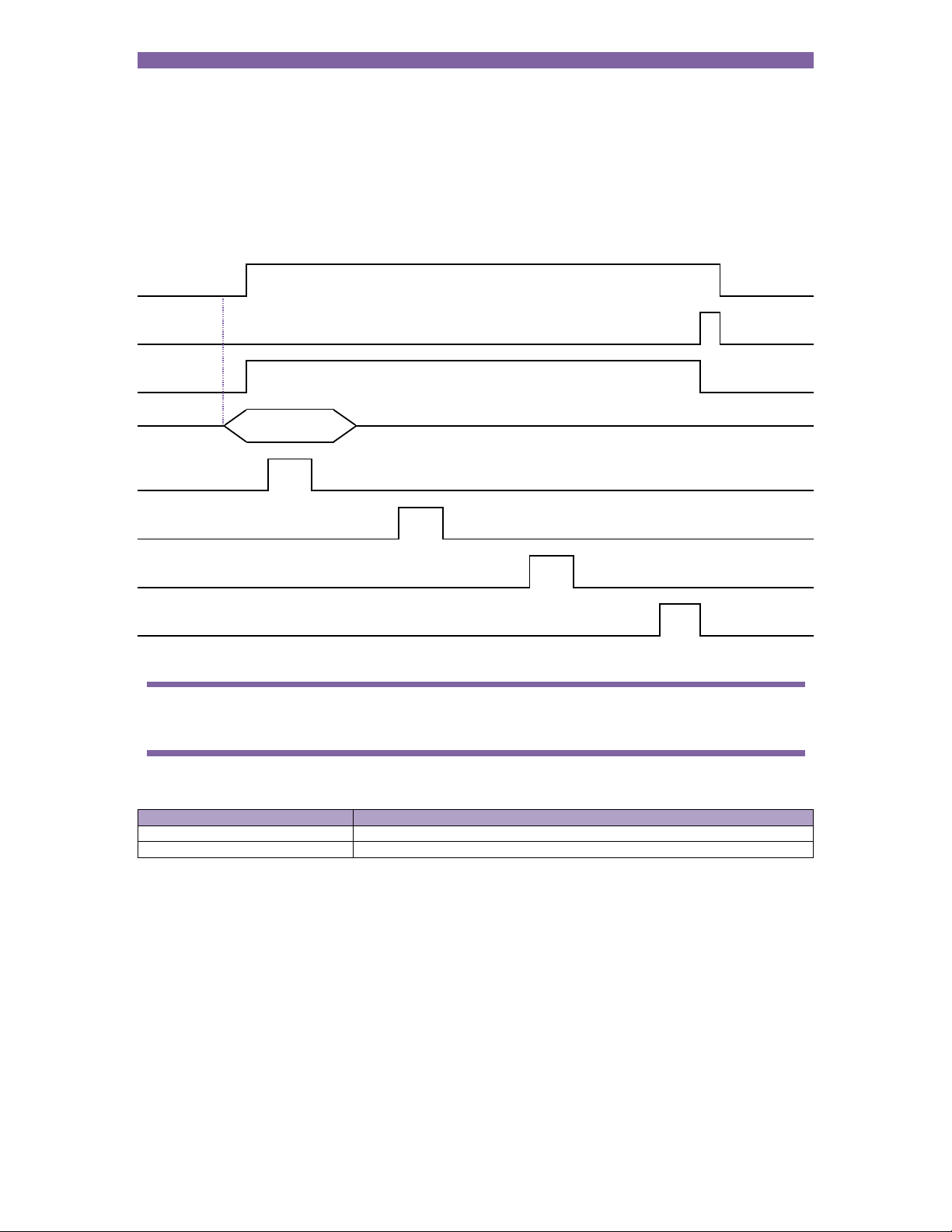
Multi-gun cascade operation
Different electrodes and transformers can still be selected but the welding programs are linked together
and started by a single Start command. Cancelling the Start command at any time will abort the cascade
sequence
Start input
EOS output
WAV output
Program
select
Current
(transformer 0)
Current
(transformer 1)
Current
(transformer 2)
Current
(transformer 3)
First
program #
In multi-gun cascade operation the program select inputs select the first program in the cascade.
If a fault occurs during a cascade sequence:
Stop on fault1 Description
Off Cascade will continue. Fault output will remain on only until next weld.
On Cascade will pause. Cascade will continue when the fault is reset.
1
Section 12 Configuration
Page 54

Section 12 Configuration 54
Seam welding (extended feature)
iPAK2 can be used for seam welding applications. The seam program parameters provide a flexible sequence
that works in conjunction with the inputs and outputs to produce several different types of seam weld e.g.
continuous seam
seam pulsation
seam modulation
seam pre-heat
roll-spot
The parameters are described in Section 6 Weld control and can be adjusted during the weld. Intervals that are
not required may be set to 0.
Page 55
Section 12 Configuration 55
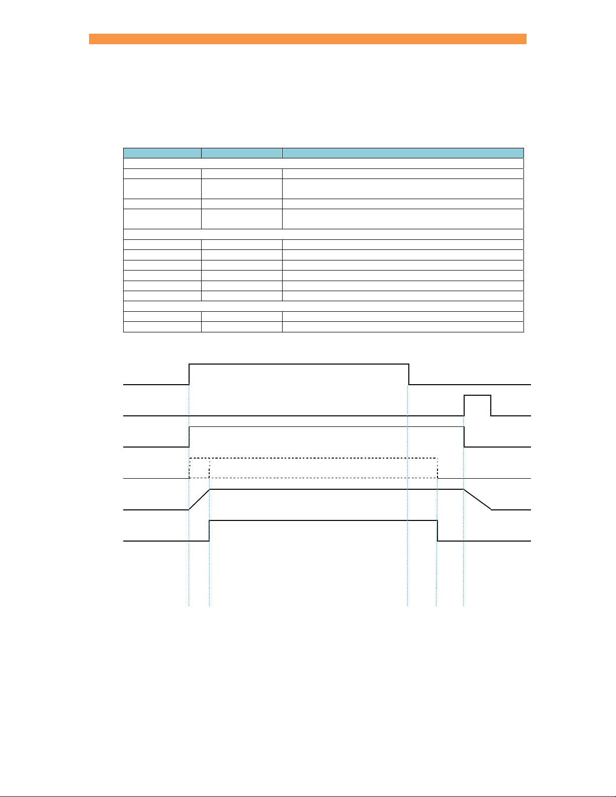
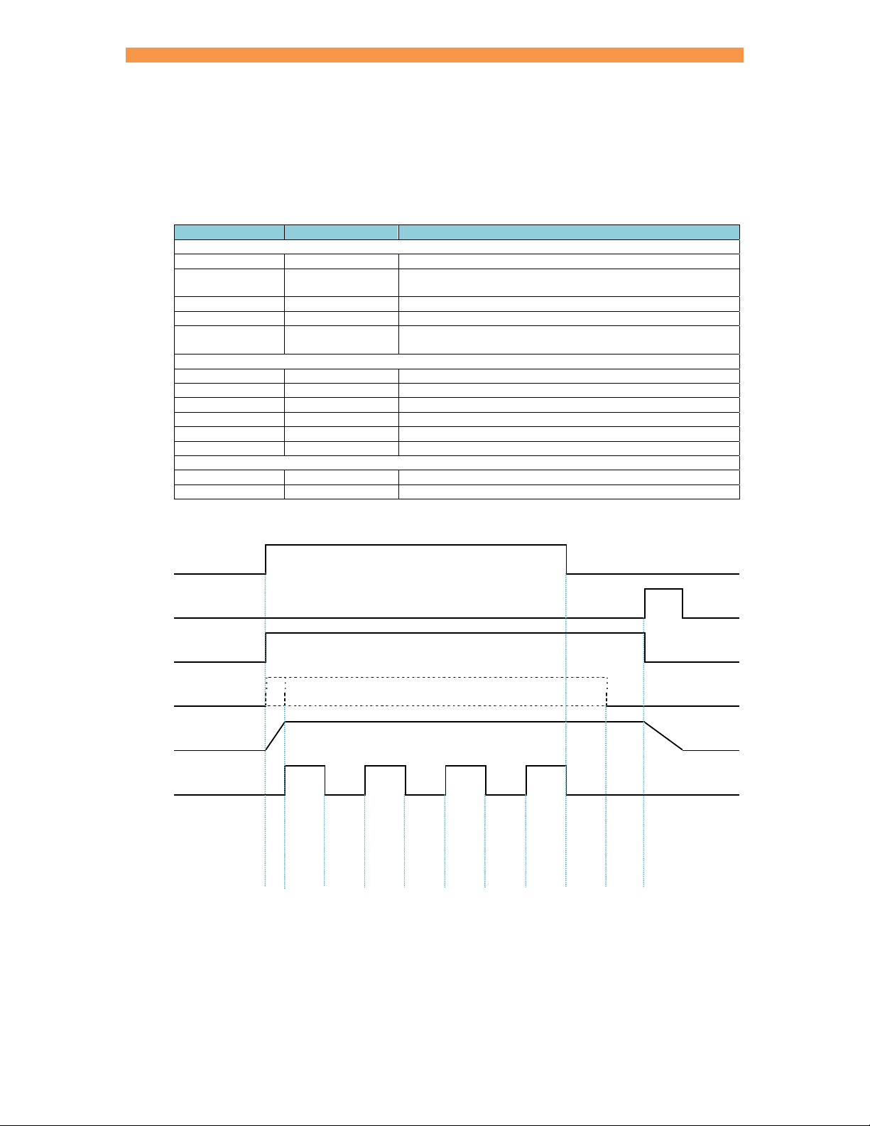
Continuous seam
A continuous seam weld maintains a set current for the duration of the weld. The following example shows how
this type of sequence may be implemented.
Parameter Setting Description
Sequence timing
Presqueeze ms The time for the electrodes to close onto the work piece.
Squeeze ms The time between the initial application of the electrode force
Main heat ms The main welding current is applied
Hold ms Electrode force continues after the welding current has
Current control
Main mode P/W – CCu –CCC Operating mode of the Main heat interval
Main heat % The % heat used during the Main heat interval
Main current kA The current used during the Main heat interval
Main monitor1 yes/no The current can be tested between limits
Low limit1 % Current low limit
High limit1 % Current high limit
Options
Pre-heat no Disable the Pre-heat parameters
Post-heat no Disable the Post-heat parameters
1
optional
Start input1
EOS output
WAV output
Motor output2
Force
Current
and the first application of welding current
finished
Interval
1
The Main heat interval is repeated until the Start input is removed.
2
The operation of the motor output is determined by the 2nd stage test (Section 12 Configuration).
Squeeze
Man
heat
Hold
Page 56
Section 12 Configuration 56
q
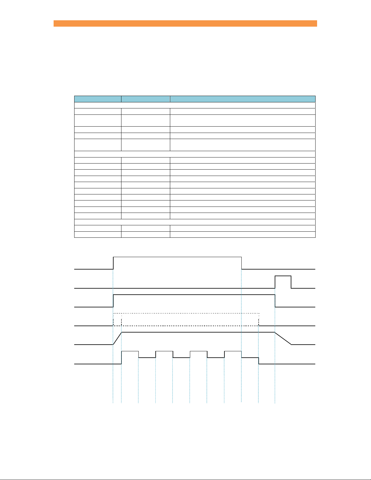
Seam pulsation
Seam pulsation can be used in applications where a continuous weld is not required. The Main heat and the
Cool2 intervals are repeated for the duration of the weld. The following example shows how this type of sequence
may be implemented.
Parameter Setting Description
Sequence timing
Presqueeze ms The time for the electrodes to close onto the work piece.
Squeeze ms The time between the initial application of the electrode force
Main heat ms The main welding current is applied
Cool2 ms The material is allowed to cool with electrode force applied
Hold ms Electrode force continues after the welding current has
Current control
Main mode P/W – CCu – CCC Operating mode of the Main heat interval
Main heat % The % heat used during the Main heat interval
Main current kA The current used during the Main heat interval
Main monitor1 yes/no The current can be tested between limits
Low limit1 % Current low limit
High limit1 % Current high limit
Options
Pre-heat no Disable the Pre-heat parameters
Post-heat no Disable the Post-heat parameters
1
optional
Start input1
EOS output
WAV output
Motor output2
Force
Current
and the first application of welding current
finished
ueeze
Interval
1
The Main heat – Cool2 intervals are repeated until the Start input is removed.
2
The operation of the motor output is determined by the 2nd stage test (Section 12 Configuration).
S
Main
heat
Cool2
Main
heat
Cool2
Main
heat
Cool2
Main
heat
Cool2
Hold
Page 57
Section 12 Configuration 57
q
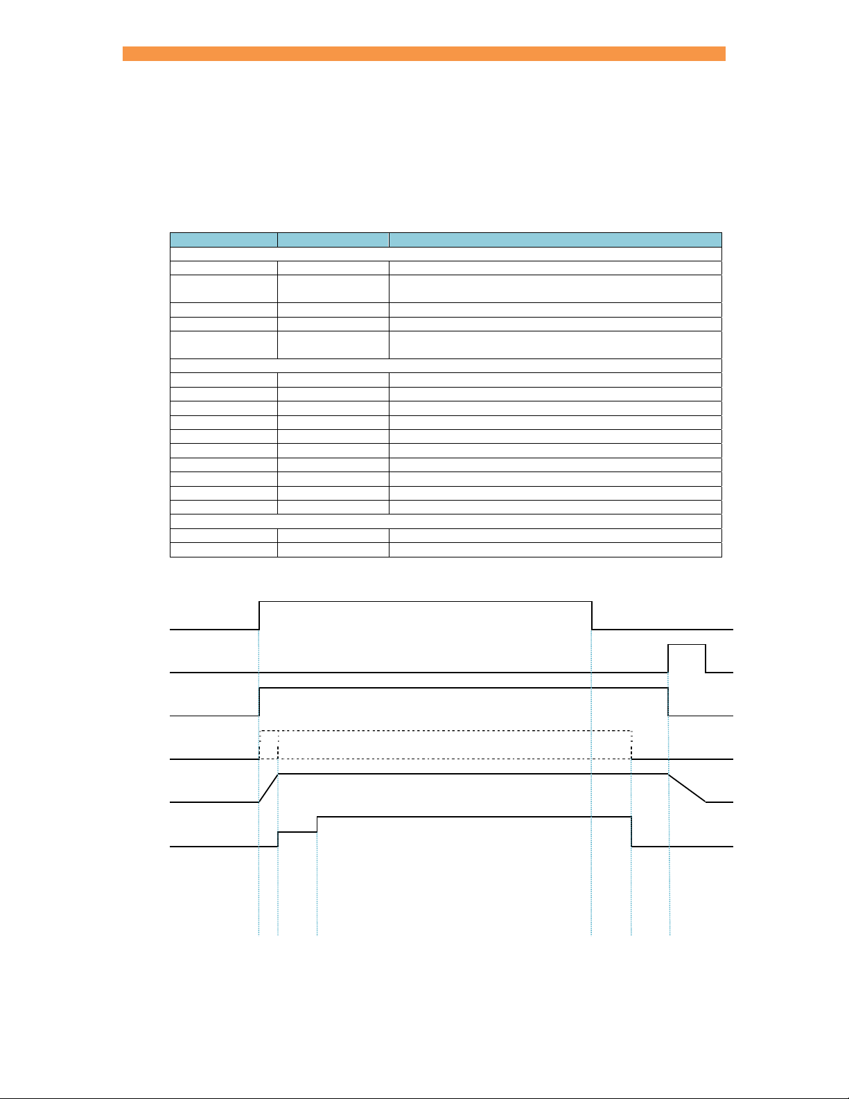
Seam modulation
Seam modulation can be used in applications where a change in current is required. Two Heat intervals are
repeated for the duration of the weld. The following example shows how this type of sequence may be
implemented.
Parameter Setting Description
Sequence timing
Presqueeze ms The time for the electrodes to close onto the work piece.
Squeeze ms The time between the initial application of the electrode force
Main heat ms The main welding current is applied
Post-heat ms The post-heat welding current is applied
Hold ms Electrode force continues after the welding current has
Current control
Main mode P/W – CCu – CCC Operating mode of the Main heat interval
Main heat % The % heat used during the Main heat interval
Main current kA The current used during the Main heat interval
Main monitor1 yes/no The current can be tested between limits
Post mode P/W – CCu – CCC Operating mode of the Post-heat interval
Post heat % The % heat used during the Post-heat interval
Post current kA The current used during the Post-heat interval
Post monitor1 yes/no The current can be tested between limits
Low limit1 % Current low limit
High limit1 % Current high limit
Options
Pre-heat no Disable the Pre-Heat parameters
Post-heat yes Enable the Post-heat parameters
1
optional
Start input1
EOS output
WAV output
Motor output2
Force
Current
and the first application of welding current
finished
ueeze
Interval
1
The Main heat – Post-heat intervals are repeated until the Start input is removed.
2
The operation of the motor output is determined by the 2nd stage test (Section 12 Configuration).
S
Main
heat
Post-
heat
Main
heat
Post-
heat
Main
heat
Post-
heat
Main
heat
Post-
heat
Hold
Page 58
Section 12 Configuration 58
q
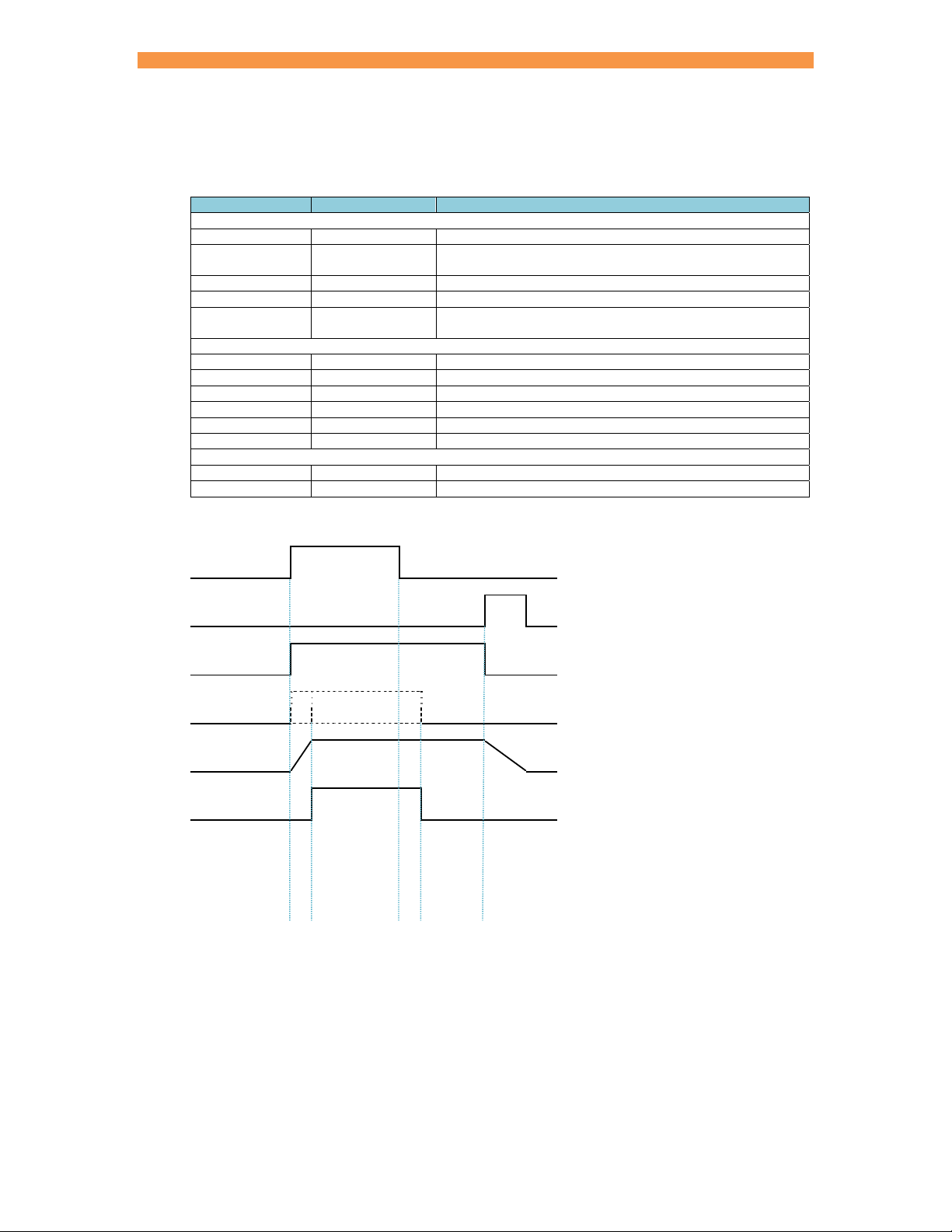
Seam pre-heat
Pre-heat can be used in applications where the initial current needs to be different to the main current. The
following example shows a continuous seam weld with a pre-heat.
Parameter Setting Description
Sequence timing
Presqueeze ms The time for the electrodes to close onto the work piece.
Squeeze ms The time between the initial application of the electrode force
Pre-heat ms The pre-heat welding current is applied
Main heat ms The main welding current is applied
Hold ms Electrode force continues after the welding current has
Current control
Pre-mode P/W – CCu –CCC Operating mode of the Pre-heat interval
Pre-heat % The % heat used during the Pre-heat interval
Pre-current kA The current used during the Pre-heat interval
Pre-monitor1 yes/no The current can be tested between limits
Main mode P/W – CCu –CCC Operating mode of the Main heat interval
Main heat % The % heat used during the Main heat interval
Main current kA The current used during the Main heat interval
Main monitor1 yes/no The current can be tested between limits
Low limit1 % Current low limit
High limit1 % Current high limit
Options
Pre-heat yes Enable the Pre-heat parameters
Post-heat no Disable the Post-heat parameters
1
optional
Start input1
EOS output
WAV output
Motor output2
Force
Current
and the first application of welding current
finished
ueeze
Interval
1
The Main heat interval is repeated until the Start input is removed.
2
The operation of the motor output is determined by the 2nd stage test (Section 12 Configuration).
S
Pre-heat
Main
heat
Hold
Page 59
Section 12 Configuration 59
q
Seam pre-heat only
Pre-heat can be used in situations when a spot weld is required. The following example shows how to use the
pre-heat to produce a spot weld.
Parameter Setting Description
Sequence timing
Presqueeze ms The time for the electrodes to close onto the work piece.
Squeeze ms The time between the initial application of the electrode force
Pre-heat ms The pre-heat welding current is applied
Main heat 0 The main welding current is not used
Hold ms Electrode force continues after the welding current has
Current control
Pre-mode P/W – CCu – CCC Operating mode of the Pre-heat interval
Pre-heat % The % heat used during the Pre-heat interval
Pre-current kA The current used during the Pre-heat interval
Pre-monitor1 yes/no The current can be tested between limits
Low limit1 % Current low limit
High limit1 % Current high limit
Options
Pre-heat yes Enable the Pre-heat parameters
Post-heat no Disable the Post-heat parameters
1
optional
Start input1
EOS output
WAV output
Motor output2
Force
Current
and the first application of welding current
finished
ueeze
Interval
1
The Pre-heat interval is interlocked.
2
The operation of the motor output is determined by the 2nd stage test (Section 12 Configuration).
S
Pre-heat
Hold
Page 60
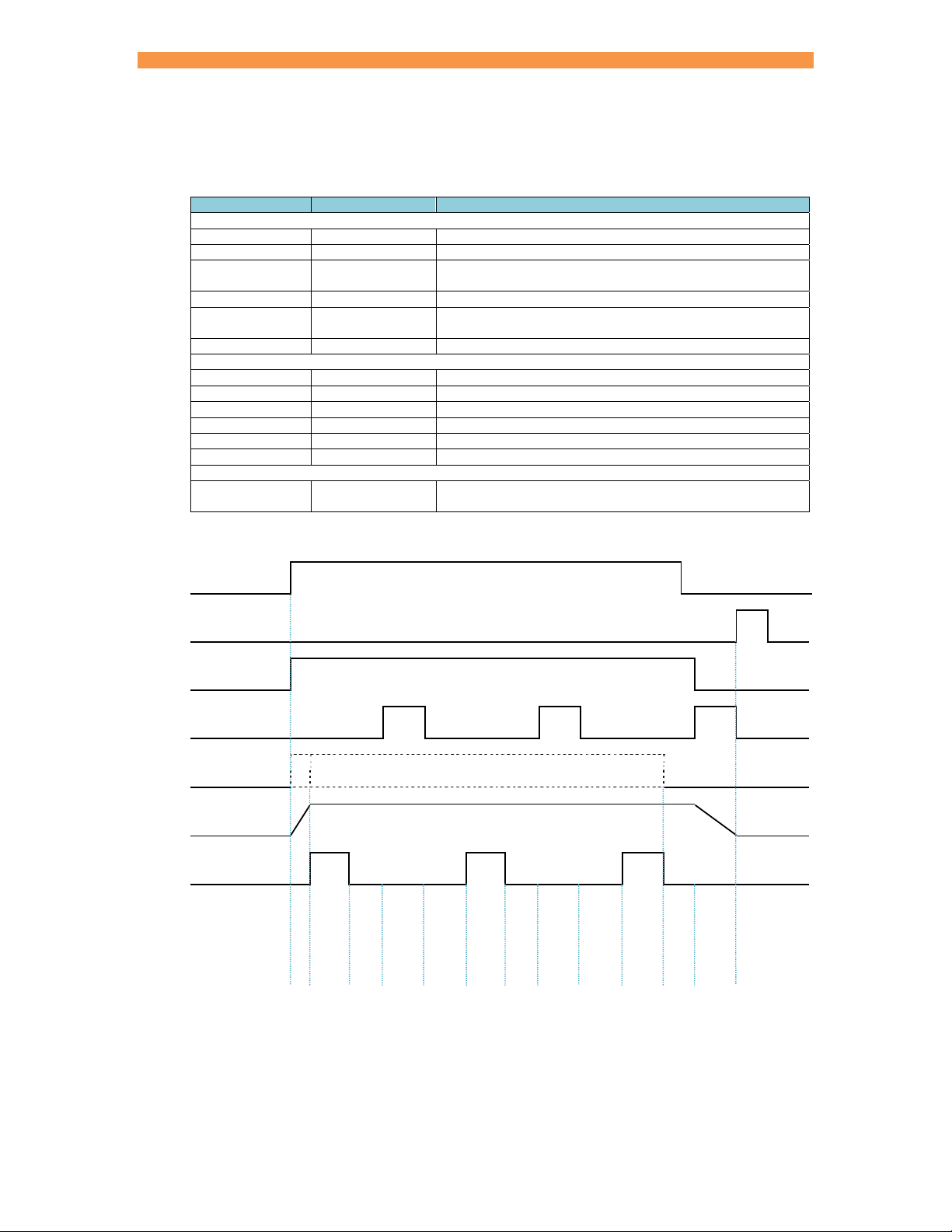
Section 12 Configuration 60
q
Roll-spot
Roll-spot welds can be used in applications where a motor drive output is required between welds. The following
example shows how this type of sequence may be implemented.
Parameter Setting Description
Sequence timing
Roll-spot on Sets roll-spot mode
Presqueeze ms The time for the electrodes to close onto the work piece.
Squeeze ms The time between the initial application of the electrode force
Main heat ms The main welding current is applied
Hold ms Electrode force continues after the welding current has
Off ms The time during which the motor drive operates
Current control
Main mode P/W – CCu – CCC Operating mode of the Main heat interval
Main heat % The % heat used during the Main heat interval
Main current kA The current used during the Main heat interval
Main monitor1 yes/no The current can be tested between limits
Low limit1 % Current low limit
High limit1 % Current high limit
Valves
AVn Off time Connect the motor drive to the valve that is activated during
1
optional
Start input1
EOS output
WAV output
AVn output
Motor output2
Force
Current
and the first application of welding current
finished
Off time
ueeze
Interval
1
The weld sequence is repeated until the Start input is removed.
2
The operation of the motor output is determined by the 2nd stage test (Section 12 Configuration).
S
Main
heat
Hold
Off
Squeeze
Main
heat
Hold
Off
Squeeze
Main
heat
Hold
Off
The examples show how the seam weld parameters can be used in any combination to implement several
different types of weld sequence.
Page 61
Section 12 Configuration 61
Configuration
The Configuration parameters affect the operation of the iPAK2.
Parameter Value Description
Features
Weld type
2nd stage
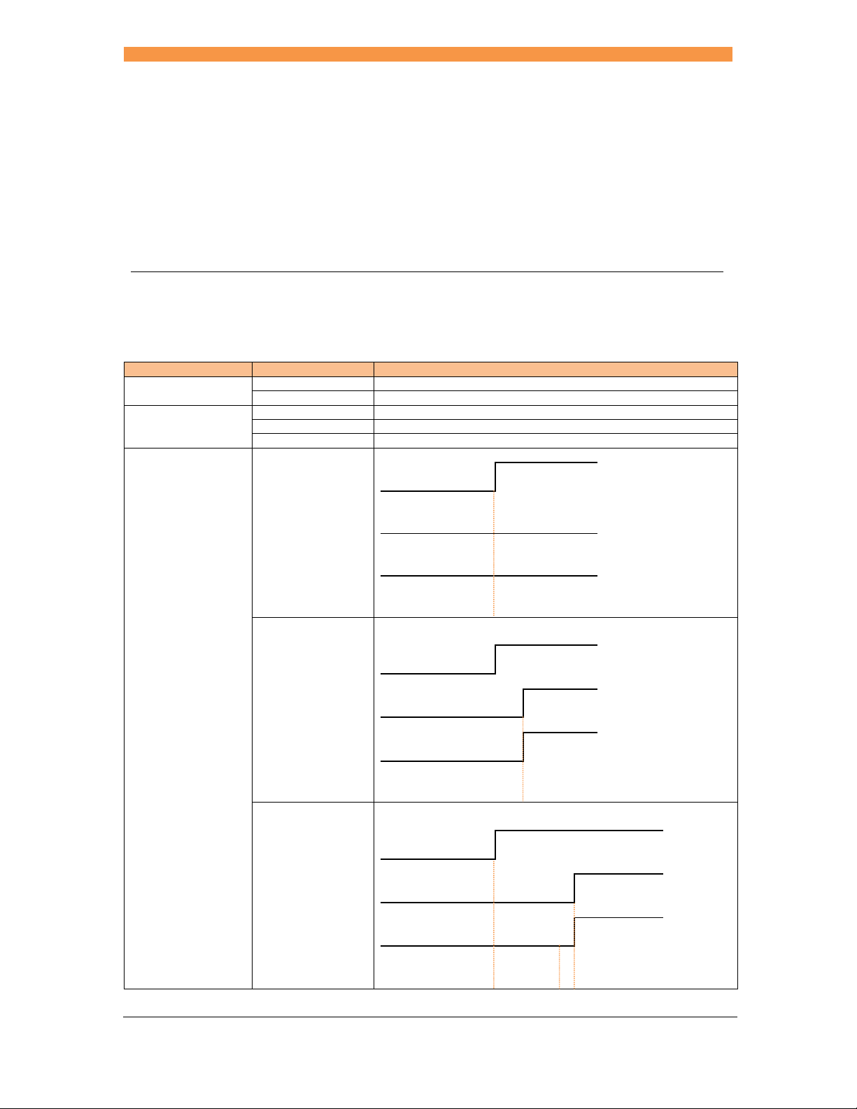
Standard Use standard features
Extended Use extended features
Spot Use spot welding features
Seam Use seam welding features
Analog Use analog welding features2
Off The 2
nd
stage input is not used. The motor output is not used1.
Start input
2nd stage input
Motor output
Sequence
begins
Before Squeeze The 2nd stage input is checked before the Squeeze interval. The
motor output is activated when the 2
Squeeze
nd
stage input is confirmed1.
Start input
2nd stage input
Motor output
After Squeeze The 2nd stage input is checked after the Squeeze interval. The
motor output is activated when the 2
Sequence
begins
Squeeze
nd
stage input is confirmed1.
Start input
2nd stage input
Motor output
Sequence
begins
Squeeze
Sequence
continues
Page 62
Section 12 Configuration 62
2nd stage
Retract
Once The 2
nd
stage input is checked only at the start of a cascade
sequence
Every The 2nd stage input is checked at the start of every program within
a cascade sequence
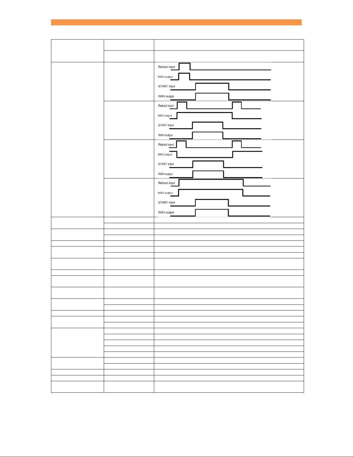
Simple
Hilift +
Hilift -
Maintained
Measure
Regulation
Primary Measure primary welding current
Secondary Measure secondary welding current (requires a toroid connection)
Primary Regulate primary current
Secondary Regulate secondary current (requires a toroid connection)
Ip limit 0 – inverter specific Sets an upper limit on the inverter output current3
Units
Stop on fault
Metric Measure force in KN
Imperial Measure force in lbf
yes/no The weld air-valve opens as normal but subsequent welds are
inhibited until a fault reset is given
EOS on fault yes/no The EOS output will be activated
Headlock on fault
iPAK (v1) mode
Program select
yes/no The weld air-valve output is held on and subsequent welds are
inhibited until a fault reset is given
yes/no Changes the sense of the READY output to NOT READY. AV4, 5
and 6 are used for MUX selection.
External The Program Select inputs select the weld program
Internal The Use Program parameter selects the weld program
Use program 0 - 255 The weld program that will be used if Internal program is selected
Electrodes
Single Use one electrode for the weld programs
Multi Use up to 8 electrodes for the weld programs
Discrete Use the discrete inputs and outputs
COM0 Use MODBUS TCP/IP (Ethernet) on COM0
I/O source
COM1 Use MODBUS TCP/IP (Ethernet) on COM1
COM2 Use MODBUS RTU (RS485) on COM2
COM3 Use RS232 on COM3
Analog output
Force The analog output is used to control force
Current The analog output corresponds to the measured weld current
Analog scaling 10V = 0 – 500kA The analog output scaling
Contactor 0 – 99 seconds The contactor output is sustained for this time following a weld
Toroid test Off / On The connection to an external toroid will be tested. The measured
1
Seam mode only
resistance must lie within the range 10 to 300 Ohms.
Page 63
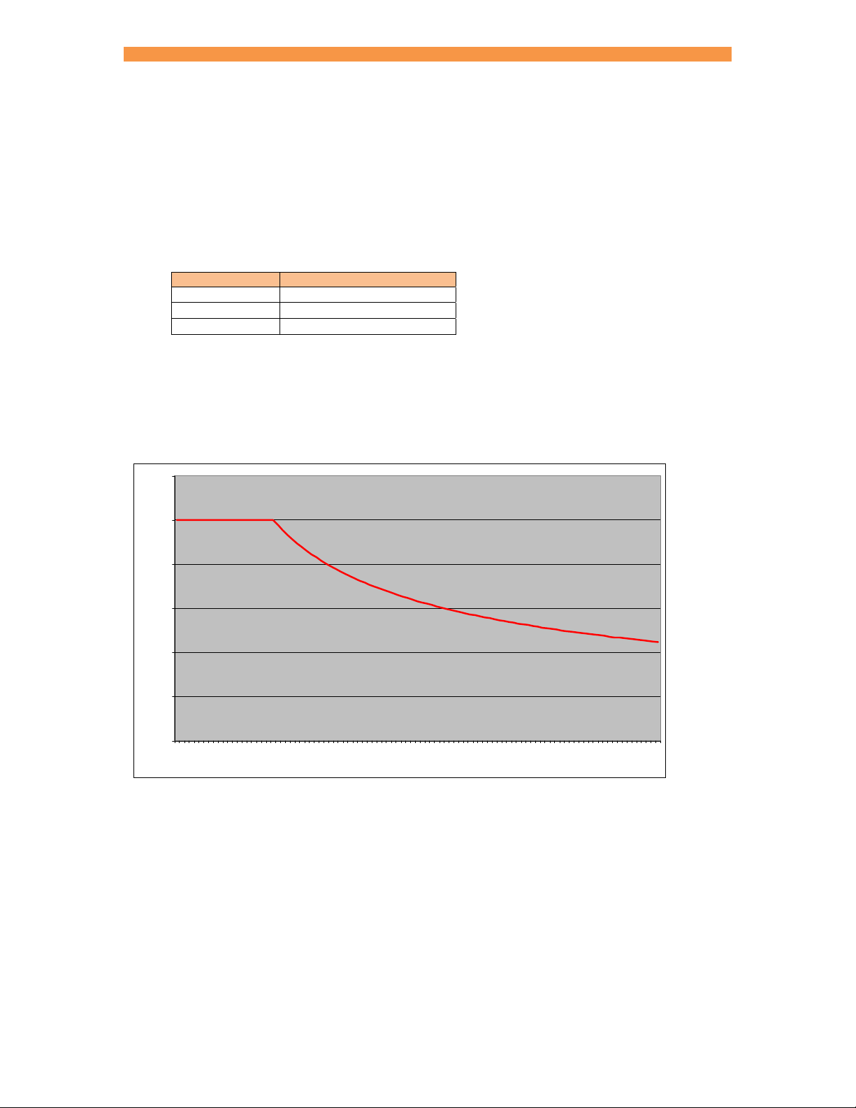
Section 12 Configuration 63
2
Analog control
In this mode of operation, the inverter output current can be controlled by applying a 0 to 10 Volt signal to P4 pins
1(+) and 2(-). A Seam sequence is produced, but note:
Pre-heat and post-heat are not available
Force feedback is not available
The input signal will control a different parameter depending on the mode set in the selected weld program:
Main mode 0 to 10 V input signal controls
P/W 0 to 100% pulse-width
CCu 0 to 100% heat
CCC 0 to 100% current
3
Duty cycle limiter
Duty is calculated over a 2 second averaging time. The inverter rating applies at up to 20% duty. At higher duties
the maximum output current must be de-rated as shown by the curve below:
1.20
1.00
0.80
0.60
De-rating factor
0.40
0.20
0.00
0 102030405060708090100
% Du t y
The iPAK2 protects against weld sequences that would exceed the allowable duty cycle. In this event the inverter
will
Stop at the end of a spot weld
Stop immediately in a seam weld
The READY signal will be de-asserted and an error message given. Further initiation is prohibited. Perform a
‘RESET FAULT’ operation to clear.
Page 64

Section 13 Programming 64
Programming
iPAK2 supports several programming methods:
NetFlash PC program (Ethernet)
WSP3 pendant (RS232)
MODBUS (Ethernet or RS485)
EtherNet/IP (via optional adapter card) – see separate adapter card manual.
Security
There are two features which can be configured to protect access:
1. Up to five PIN codes can be stored in each control. Users must then enter their code
before being granted access permission to edit parameters. All parameters remain
viewable (read-only). This feature can be configured to be applied to the WSP3. After
initially gaining access, edit permission remains granted for a configurable time-out
period.
2. Use of an external switch connected to the P64 input pin. Users are only granted access
permission to edit parameters when the switch is activated. By using a key-switch, only
the key-holders will be able to make edits. All parameters remain viewable (read-only).
When configured, this feature applies to the WSP3.
Note that if this feature is used, then the P64 (program select bit 64) is no longer available
on the discrete signal interface and thus external selection of programs is restricted to the
range 0 to 63. This is not normally a problem on manual installations which is typically
where security features are required. The full range of programmes (0 to 255) is still
available through manual selection or via a network connection.
The above features are configured via the use of NetFlash software. NetFlash itself also has
a security feature which can be used to tailor access rights. Users can be allocated
usernames, passwords and access levels which restrict users to editing none, some or all
parameters, as required. Thus, an administrator can pass copies of NetFlash to various
personnel, each having individually permission levels.
Access via network protocols is not restricted as this will generally be via automation systems.
Page 65

Section 13 Programming 65
NetFlash
NetFlash is a PC-compatible program which provides a graphical user interface to program and monitor
one or more iPAK2s. In addition NetFlash provides backup/restore functions for control data, live data
logging to a file and a utility for updating the firmware in the iPAK2.
System requirements
NetFlash is a Microsoft Windows compatible PC program. It requires the latest Java Runtime
Environment which is available from https://java.com/download. The minimum screen resolution is 1280
x 1024.
Installation
NetFlash does not need to be installed. Copy the NetFlash folder and its contents from the supplied
media to the PC and run the NetFlash.exe program.
Removal
NetFlash does not need to be uninstalled. To remove NetFlash delete the NetFlash folder and its
contents from the PC.
Page 66
Section 13 Programming 66
Connection
NetFlash uses 10/100 Base-T Ethernet to communicate with the iPAK2.Ensure that the PC has an
appropriate Ethernet adapter and that a network connection is in place. Use COM0/1 to connect the
iPAK2 to the network
PC + NetFlash
Hub or switch
iPAK2 Ethernet enabled device Ethernet enabled device
If no network is available the PC can be connected directly to the iPAK2:
PC + NetFlash
Set the IP address in the iPAK2 (Section 15 Appendix). Set the IP address in the PC (contact your
system administrator). For example:
PC 192.168.0.99 255.255.255.0
Welding control 192.168.0.103 255.255.255.0
Contact the system administrator for further details.
IP address Subnet mask
iPAK2
Page 67
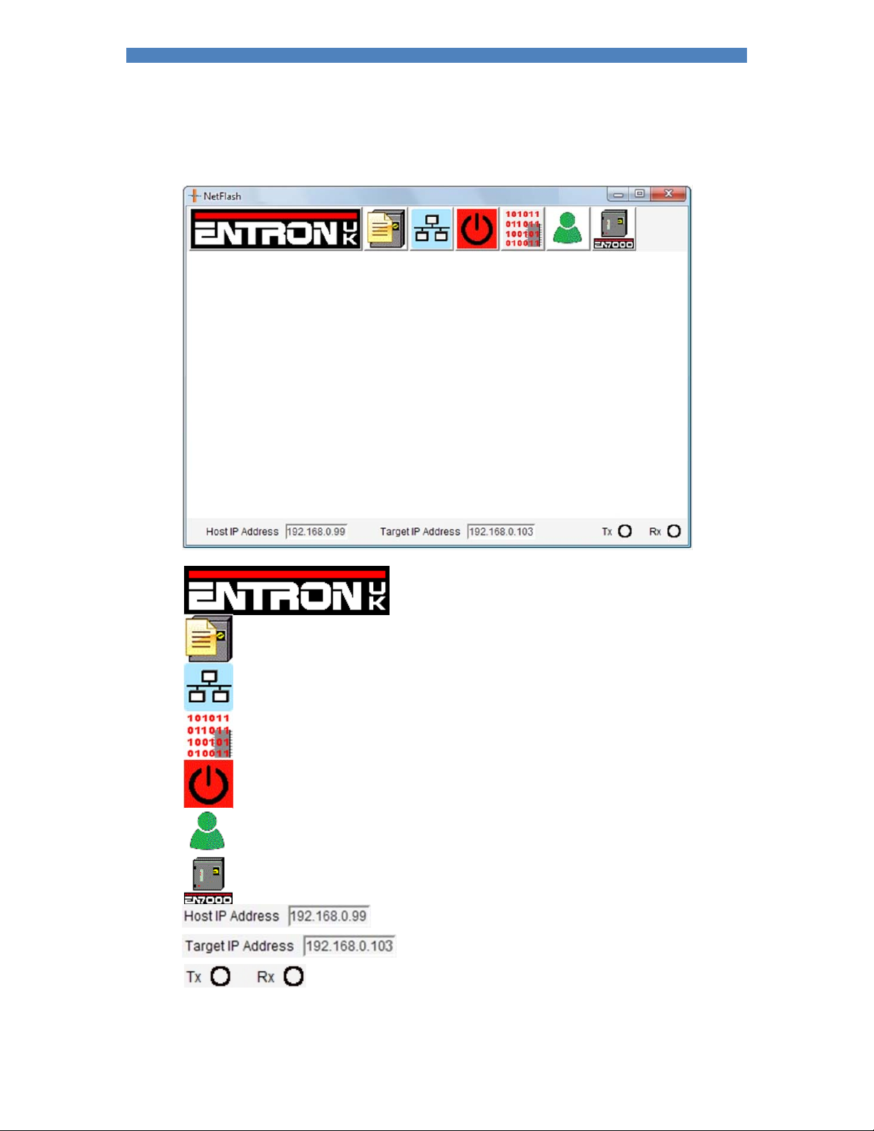
Section 13 Programming 67
Initialisation
Run the NetFlash.exe program. The home screen is shown:
Displays ENTRON UK contact details
Edit iPAK2 parameters. Allows access to the iPAK2
parameters via the network or from a file.
Network configuration. Locates welding controls on the network
Flash programming tool. Allows the firmware in the iPAK2 to be
updated
Restart weld control. Restarts the iPAK2 following a change to
an application-specific parameter
Security features
Control type
Shows the PC’s IP address
Shows the IP address of the target iPAK2
Shows communication activity on the network
Page 68
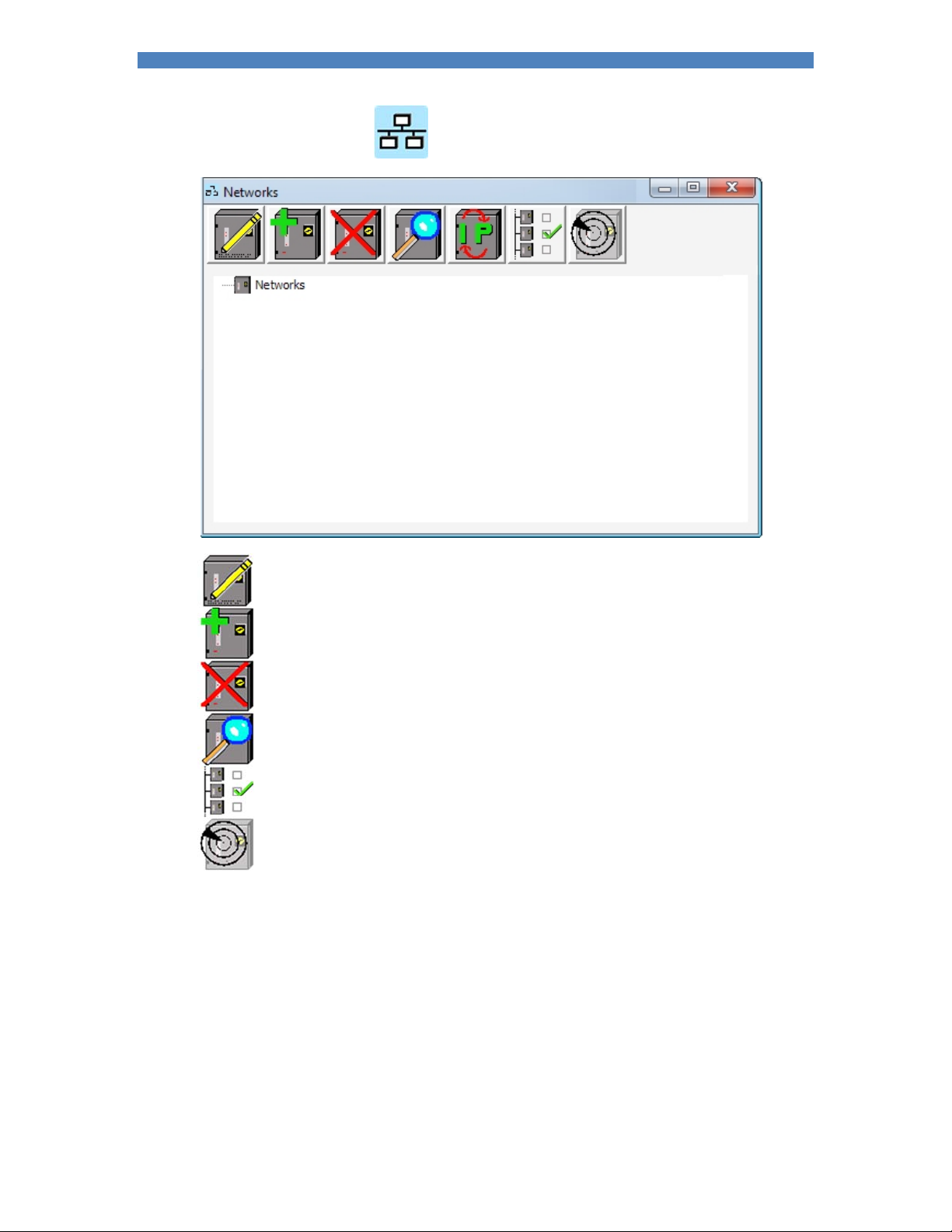
Section 13 Programming 68
Select Network Configuration . The following screen is shown:
Edit timer location. Welding controls that have been detected on the network can be
assigned descriptive names and locations. This function allows the names and locations to
be edited.
Add a welding control to the network
Remove a welding control from the network
Scan for welding controls on the network
Use the selected welding control as the target welding control when editing
Perform a low-level communications test on the selected welding control
Page 69
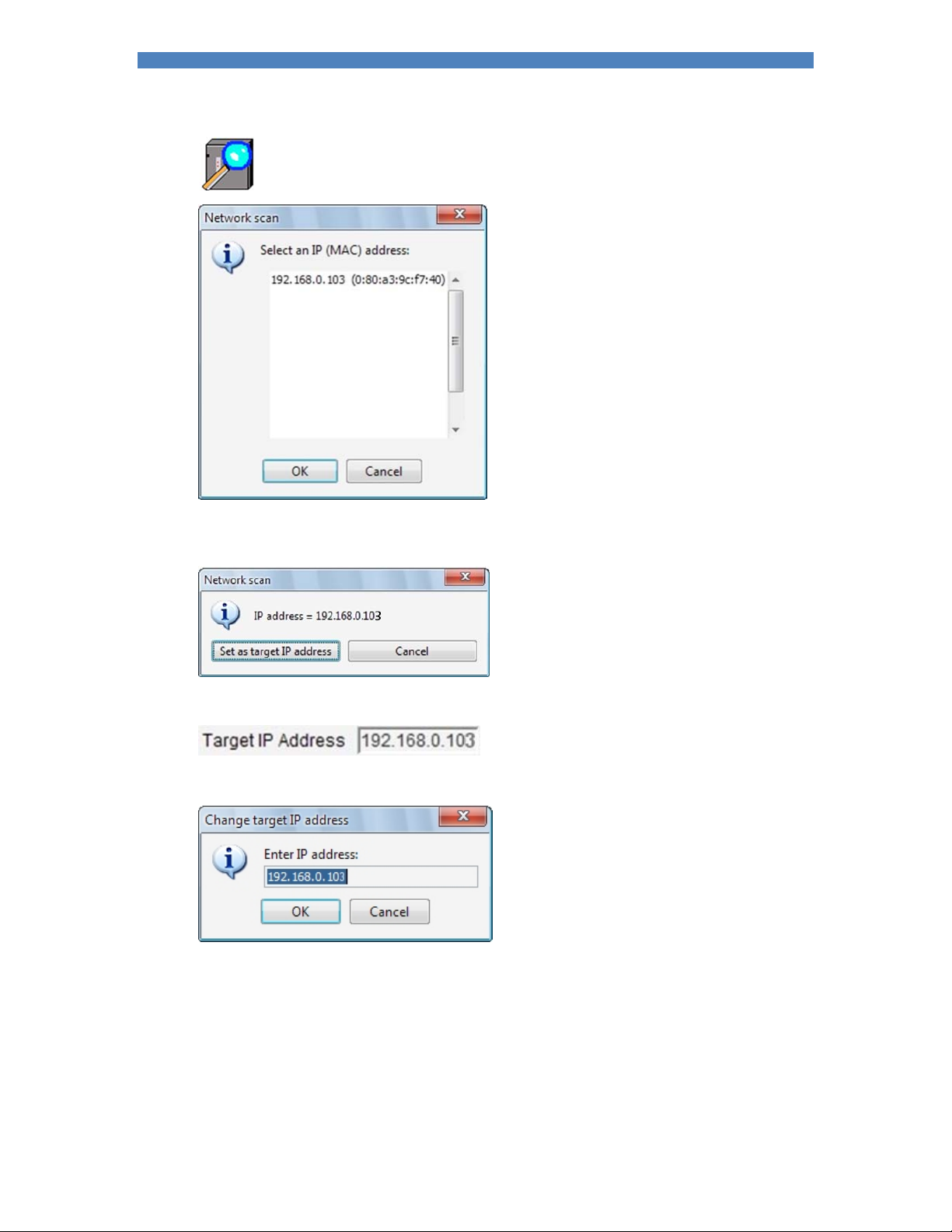
Section 13 Programming 69
Select Scan network for timers. NetFlash will show the compatible welding controls on the
network:
Select an IP address and then select OK. NetFlash will ask if the address should be used as the target
welding control for editing:
If Set as target IP address is selected the IP address will be shown as the target IP address:
Alternatively, the target address can be set by using the Edit button:
To add a descriptive name and/or location for the welding control, use the Add welding control function.
It is not necessary to do this if only one welding control is being used.
When a welding control has been selected as the target the parameters can be changed.
Page 70
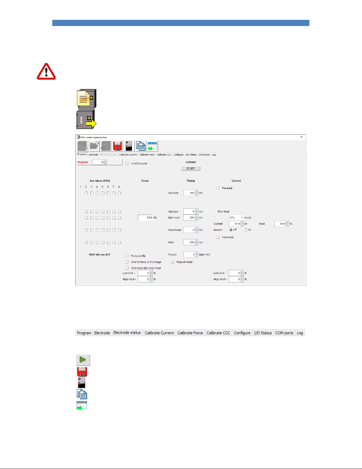
Section 13 Programming 70
Parameters
Caution: when parameters are changed in NetFlash they are changed immediately in the iPAK2.
Select the Edit weld parameters function from the home screen.
Select Load from timer. Data will be loaded from the target welding control:
The Program screen is shown. This screen contains the parameters that control the weld sequence for
the selected weld program
NetFlash uses tabs to navigate the parameter categories. Select the appropriate tab to edit the
parameters:
Other functions are provided:
Show associated parameters in a different category
Save the parameters in a file
Open or close the metrics window. NetFlash shows the results of the last weld and the
status messages
Copy programs
Export the parameters to a CSV file
Page 71
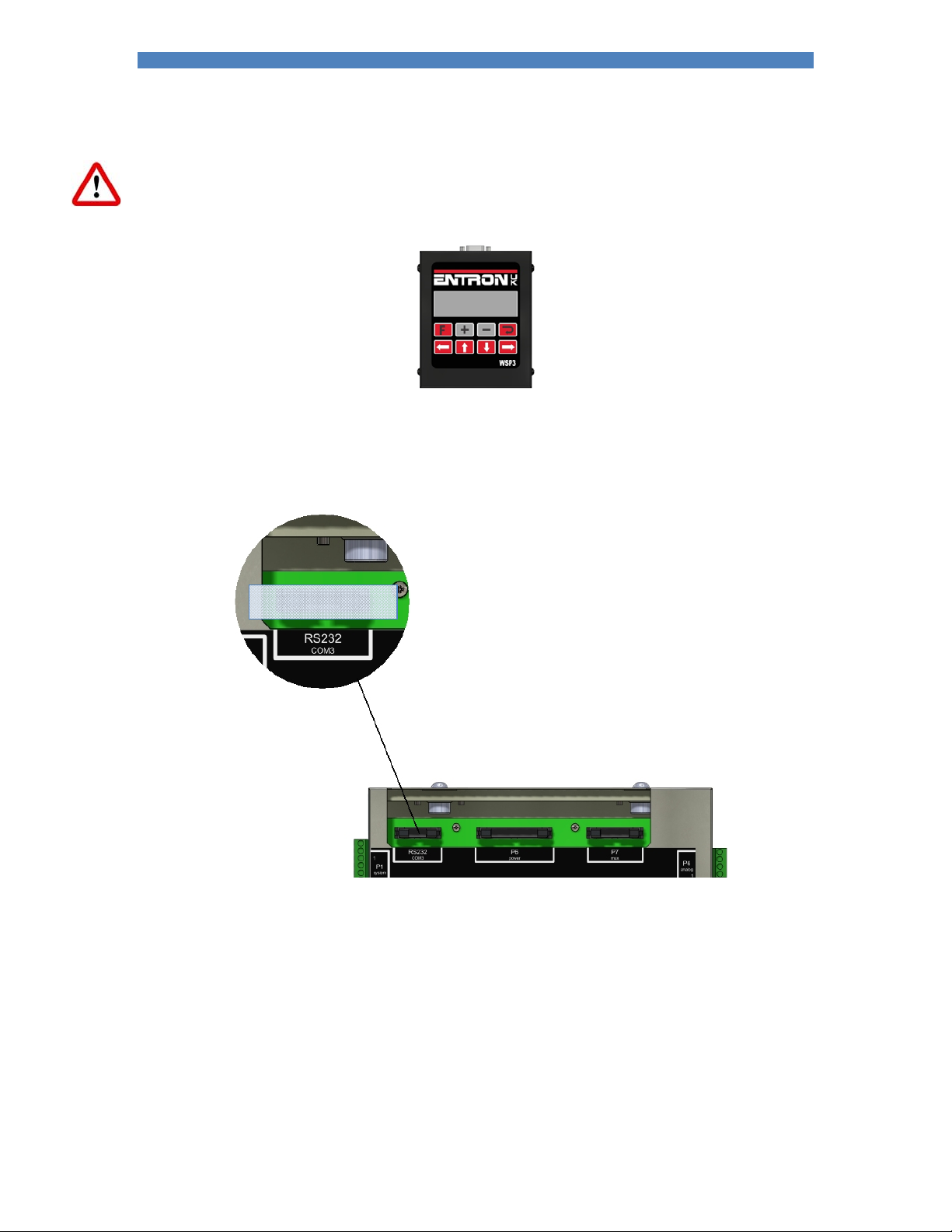
Section 13 Programming 71
WSP3
Caution: when parameters are changed with the WSP3 they are changed immediately in the iPAK2.
The WSP3 is a hand-held programming pendant with a 20x4 character display and a sealed keypad.
The WSP3 can be used to access diagnostic information in addition to all parameters.
The WSP3 uses RS232 to communicate with the iPAK2 and should be connected to COM3:
WSP3
Page 72
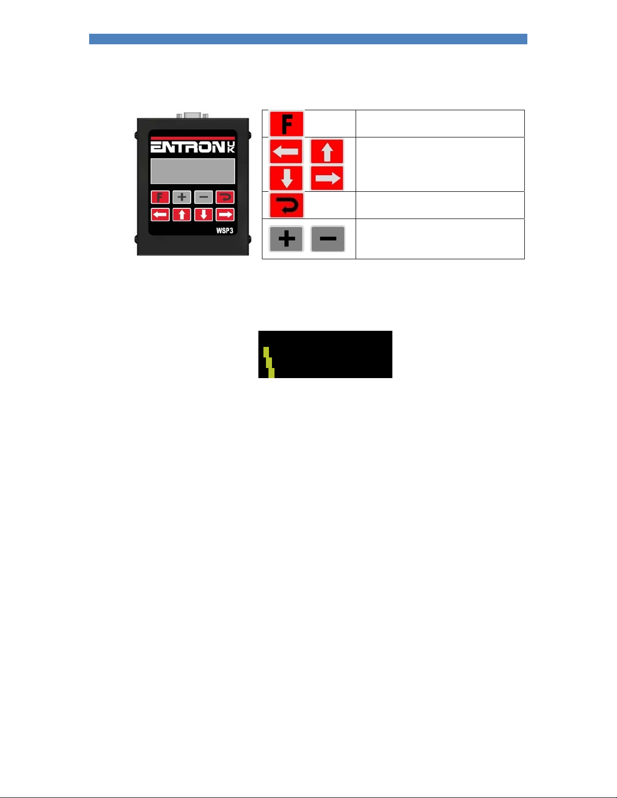
Section 13 Programming 72
Keypad
Return to the previous screen or move
between menu screens.
Select a different function or parameter.
The selected function or parameter will
flash and the visible window will scroll if
required.
Access the selected function.
Alter the selected parameter. Press both
keys together to set the parameter to 0 or
to its minimum value.
Diagnostic screen
Status
Measured Pre-current
Measured Main current
Measured Post-current
If more than one status message is present they are shown sequentially.
Ready
|‐‐0Aprog7
‐|‐11.7kA5.66kN
‐‐ | 0A ~30.5%
Program used
Measured force
Measured pulse-width
Page 73
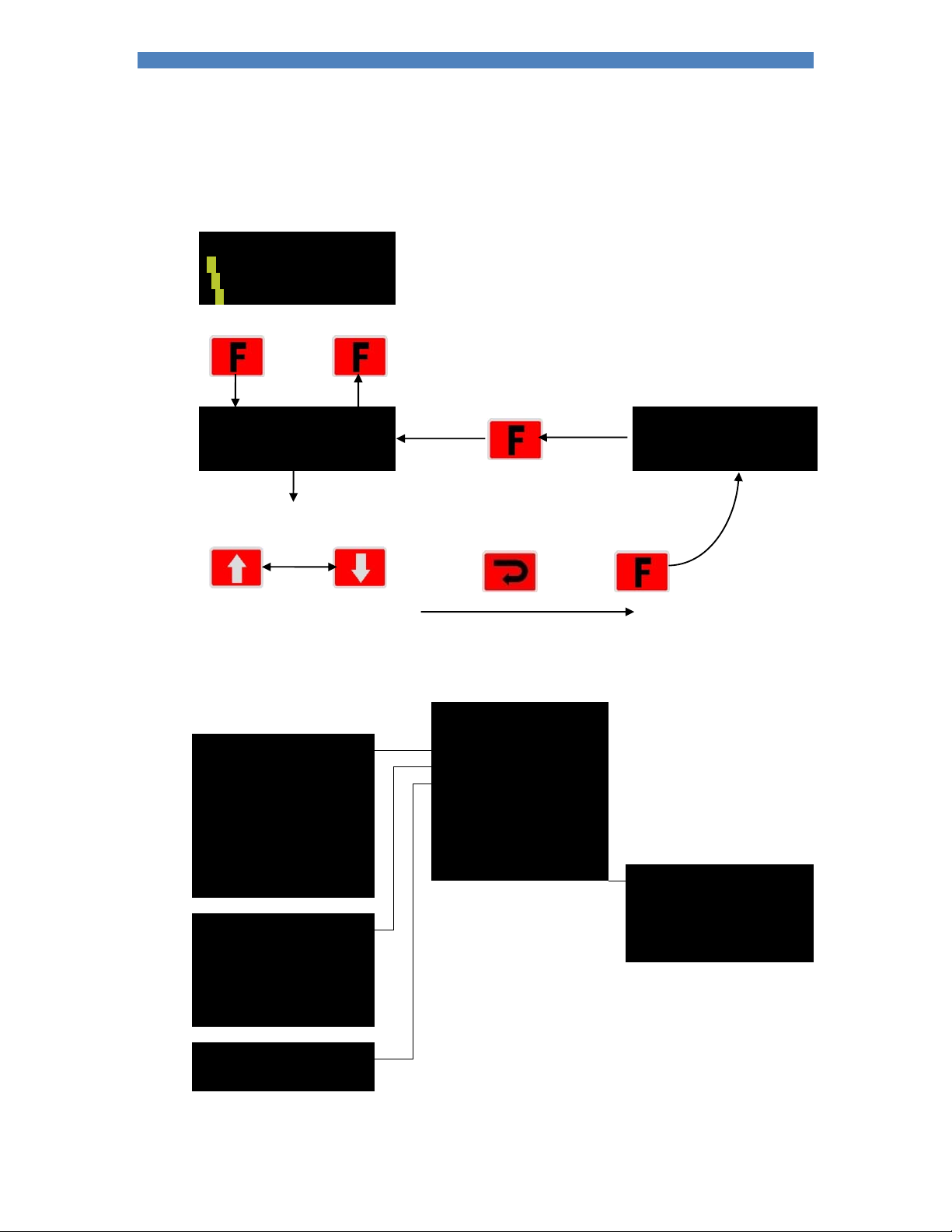
Section 13 Programming 73
Menus
The functions of the iPAK2 are arranged into a set of menus and screens as follows:
Diagnostic screen
Ready
|‐‐0Aprog7
‐|‐11.7kA5.66kN
‐‐|0A~30.5%
<<<MAINMENU>>>
USEprogram7 01NOV201812.00.00
Editprogram WELDTYPE:SPOT
Editelectrode 2ndSTAGE:OFF
Select the first or the last line
of the Main Menu…
<< mainmenu>>
Edittime Editelectrode
Editcurrent Historylog
Editforce DiscreteI/Ostatus
Editvalves BusI/Ostatus
Editoptions Analogi/ostatus
Electrode Inverterinformation
Linktoprogram Systeminformation
Copyprogram Editconfiguration <<configuremenu>>
Startprogram
Backuptowsp3
Editcounter Initialisedata
Editstepper Restartsystem
Calibratecurrent
Calibratecccmode
Calibrateforce
Copyelectrode
Viewlog
Clearlog
Press and
<<programmenu>> Editprogram
<<electrodemenu>> Restorefromwsp3
<<historylog>>
hold…
Useprogram
…then
press
<<<configure>>>
[Configuration parameters]
Page 74

Section 13 Programming 74
Backup/Restore
The WSP3 allows the data in one iPAK2 to be transferred to another by using the Backup and Restore
functions.
Use the Backup function to make a copy of all the iPAK2’s settings. The copy is held
within the WSP3. The data in the iPAK2 is unchanged. Note that only one backup can
be stored in the WSP3 and that this is overwritten each time the backup function is
used.
Use the Restore function to restore all of the settings in the iPAK2 from a backup
stored in the WSP3 pendant. Note that this operation will overwrite all data which was
previously stored in the iPAK2. After the restore operation the backup remains in the
WSP3.
Initialise data
The Initialise function sets all of the parameters in the iPAK2 to predefined values.
The Initialise function will overwrite all previously stored data in the iPAK2. After an initialise operation,
review the configuration and calibration settings and ensure they are appropriate for the application.
Also review the welding programs that will be used.
The initialise function can be used when first setting up an iPAK2.
Page 75
Section 13 Programming 75
MODBUS
A PLC or HMI MODBUS master can be used to program an iPAK2. All parameters are directly mapped
to MODBUS registers for easy access. Both MODBUS-TCP/IP (Ethernet) and MODBUS-RTU (RS485)
protocols are supported.
Write the data using MODBUS function 16
Read the data using MODBUS function 3
MODBUS access types
Write data
Type Value Description
Function code UINT 16 Write multiple registers
Read offset UINT 0
Read length UINT 0
Write offset UINT variable
Write length UINT 1
Read data
Type Value Description
Function code UINT 3 Read holding registers
Read offset UINT variable
Read length UINT 64
Write offset UINT 0
Write length UINT 0
Page 76
Section 13 Programming 76
MODBUS mapping
Variable Address Type Description
Weld programs 256 x 64 WORDS
Weld program 0 16#0000 (= 0) WORD ARRAY [0..63]
Weld program 1 16#0040 (= 64) WORD ARRAY [0..63]
Weld program 2 16#0080 (= 128) WORD ARRAY [0..63]
Weld program 3 16#00C0 (= 192) WORD ARRAY [0..63]
… … …
Weld program 254 16#3F80 (= 16256) WORD ARRAY [0..63]
Weld program 255 16#3FC0 (= 16320) WORD ARRAY [0..63]
Electrodes 8 x 64 WORDS
Electrode 0 16#4000 (= 16384) WORD ARRAY [0..63]
Electrode 1 16#4040 (= 16448) WORD ARRAY [0..63]
Electrode 2 16#4080 (= 16512) WORD ARRAY [0..63]
Electrode 3 16#40C0 (= 16576) WORD ARRAY [0..63]
Electrode 4 16#4100 (= 16640) WORD ARRAY [0..63]
Electrode 5 16#4140 (= 16704) WORD ARRAY [0..63]
Electrode 6 16#4180 (= 16768) WORD ARRAY [0..63]
Electrode 7 16#41C0 (= 16834) WORD ARRAY [0..63]
Calibration 8 x 64 WORDS
Calibration 0 16#5000 (= 20480) WORD ARRAY [0..63]
Calibration 1 16#5040 (= 20544) WORD ARRAY [0..63]
Calibration 2 16#5080 (= 20608) WORD ARRAY [0..63]
Calibration 3 16#50C0 (= 20672) WORD ARRAY [0..63]
Calibration 4 16#5100 (= 20736) WORD ARRAY [0..63]
Calibration 5 16#5140 (= 20800) WORD ARRAY [0..63]
Calibration 6 16#5180 (= 20864) WORD ARRAY [0..63]
Calibration 7 16#51C0 (= 20928) WORD ARRAY [0..63]
Configuration 1 x 64 WORDS
Configuration 16#6000 (= 24576) WORD ARRAY [0..63]
Page 77
Section 13 Programming 77
Weld program parameters
Variable Channel Address offset Type Description
Weld program %IW0 WORD ARRAY [0..63]
Attributes Weld program [0] %IW0 WORD
Pre heat Bit 0 %IX0.0 BOOL 0 = off, 1 = on
Post heat Bit 1 %IX0.1 BOOL 0 = off, 1 = on
Pre-mode
Main mode
Post-mode
Link mode Bit 8 %IX1.0 BOOL 0 = off, 1 = on
Repeat mode Bit 9 %IX1.1 BOOL 0 = off, 1 = on
Wait force Bit 10 %IX1.2 BOOL 0 = off, 1 = on
Force profile Bit 11 %IX1.3 BOOL 0 = off, 1 = on
Test force Bit 12 %IX1.4 BOOL 0 = off, 1 = on
Test pre-current Bit 13 %IX1.5 BOOL 0 = off, 1 = on
Test main current Bit 14 %IX1.6 BOOL 0 = off, 1 = on
Test post-current Bit 15 %IX1.7 BOOL 0 = off, 1 = on
Presqueeze time Weld program [1] %IW1 WORD 0 – 1999
Squeeze time Weld program [2] %IW2 WORD 0 – 1999
Pre-heat time Weld program [3] %IW3 WORD 0 – 1999
Pre-heat Weld program [4] %IW4 WORD 0 – 1999
Reserved Weld program [5] %IW5 WORD
Pre-current Weld program [6] %IW6 DWORD 0 – 500000
Cool1 time Weld program [8] %IW8 WORD 0 – 1999
Main heat time Weld program [9] %IW9 WORD 0 – 1999
Main heat Weld program [10] %IW10 WORD 0 – 1999
Reserved Weld program [11] %IW11 WORD
Main current Weld program [12] %IW12 DWORD 0 – 500000
Cool2 time Weld program [14] %IW14 WORD 0 – 1999
Pulsations Weld program [15] %IW15 WORD 1 – 99
Post-heat time Weld program [16] %IW16 WORD 0 – 1999
Post-heat Weld program [17] %IW17 WORD 0 – 1999
Reserved Weld program [18] %IW18 WORD
Post-current Weld program [19] %IW19 DWORD 0 – 500000
Hold time Weld program [21] %IW21 WORD 0 – 1999
Off time Weld program [22] %IW22 WORD 0 – 1999
Upslope time Weld program [23] %IW23 WORD 0 – 1999
Downslope time Weld program [24] %IW24 WORD 0 – 1999
Squeeze valves1 Weld program [25] %IW25 WORD
Pre-heat valves1 Weld program [26] %IW26 WORD
Cool1 valves1 Weld program [27] %IW27 WORD
Upslope valves1 Weld program [28] %IW28 WORD
Main heat valves1 Weld program [29] %IW29 WORD
Cool2 valves1 Weld program [30] %IW30 WORD
Downslope valves1 Weld program [31] %IW31 WORD
Post-heat valves1 Weld program [32] %IW32 WORD
Hold valves1 Weld program [33] %IW33 WORD
Off valves1 Weld program [34] %IW34 WORD
1
Weld program [nn] %IXnn.0.0 BOOL AV1 state 1 = ON
Bit 2 %IX0.2 BOOL 00 = PHA, 01 = CCu,
Bit 3 %IX0.3 BOOL
Bit 4 %IX0.4 BOOL 00 = PHA, 01 = CCu,
Bit 5 %IX0.5 BOOL
Bit 6 %IX0.6 BOOL 00 = PHA, 01 = CCu,
Bit 7 %IX0.7 BOOL
Weld program [nn] %IXnn.0.1 BOOL AV2 state 1 = ON
Weld program [nn] %IXnn.0.2 BOOL AV3 state 1 = ON
Weld program [nn] %IXnn.0.3 BOOL AV4 state 1 = ON
Weld program [nn] %IXnn.0.4 BOOL AV5 state 1 = ON
Weld program [nn] %IXnn.0.5 BOOL AV6 state 1 = ON
Weld program [nn] %IXnn.0.6 BOOL AV7 state 1 = ON
Weld program [nn] %IXnn.0.7 BOOL AV8 state 1 = ON
11 = CCC
11 = CCC
11 = CCC
Page 78
Section 13 Programming 78
Weld program parameters (continued)
Variable Channel Address offset Type Description
Squeeze force Weld program [35] %IW35 WORD 0 – 327672
Pre-heat force Weld program [36] %IW36 WORD 0 – 327672
Cool1 force Weld program [37] %IW37 WORD 0 – 327672
Upslope force Weld program [38] %IW38 WORD 0 – 327672
Main heat force Weld program [39] %IW39 WORD 0 – 327672
Cool2 force Weld program [40] %IW40 WORD 0 – 327672
Downslope force Weld program [41] %IW41 WORD 0 – 327672
Post-heat force Weld program [42] %IW42 WORD 0 – 327672
Hold force Weld program [43] %IW43 WORD 0 – 327672
Off force Weld program [44] %IW44 WORD 0 – 327672
Force low limit Weld program [45] %IW45 WORD 0 – 99 %
Force high limit Weld program [46] %IW46 WORD 0 – 99 %
Selected WAV Weld program [47] %IW47 WORD 0 – 7
Current low limit Weld program [48] %IW48 WORD 0 – 99 %
Current high limit Weld program [49] %IW49 WORD 0 – 99 %
Selected electrode Weld program [50] %IW50 WORD 0 – 7
Linked program Weld program [51] %IW51 WORD 0 – 255
Last pre-current Weld program [52] %IW52 DWORD 0 – 500000
Last main current Weld program [54] %IW54 DWORD 0 – 500000
Last post-current Weld program [56] %IW56 DWORD 0 – 500000
Reserved Weld program [58] %IW58 WORD
Reserved Weld program [59] %IW59 WORD
Reserved Weld program [60] %IW60 WORD
Attributes Weld program [61] %IW61 WORD
Inhibited Bit 0 %IX61.0 BOOL 0 = enable, 1 = inhibit
Motor valves1 Weld program [62] %IW62 WORD
Reserved Weld program [63] %IW63 WORD
2
Divide value by 898.99 for kN. Divide value by 4 for lbf.
Electrode parameters
Variable Channel Address offset Type Description
Electrode %IW0 WORD ARRAY [0..63]
Attributes Electrode [0] %IW0 WORD
Enable counter Bit 0 %IX0.0 BOOL 0 = off, 1 = on
Enable tipdress Bit 1 %IX0.1 BOOL 0 = off, 1 = on
Enable stepper Bit 2 %IX0.2 BOOL 0 = off, 1 = on
Stop at endcount Bit 3 %IX0.3 BOOL 0 = off, 1 = on
Stop at endstep Bit 4 %IX0.4 BOOL 0 = off, 1 = on
Transformer Electrode [1] %IW1 WORD 0 – 7
Counter Electrode [2] %IW2 WORD 0 – 9999
Endcount Electrode [3] %IW3 WORD 0 – 9999
Dressings done Electrode [4] %IW4 WORD 0 – 9999
Max dressings Electrode [5] %IW5 WORD 0 – 9999
Stepper spots done Electrode [6] %IW6 DWORD Read only
Stepper % done Electrode [8] %IW8 WORD Read only
Stepper reset to Electrode [9] %IW9 WORD 0 – 9999
Stepper spots Electrode [10..19] %IW10..19 WORD 0 – 9999
Stepper delta H Electrode [20..29] %IW20..29 WORD 0 – 500 (% x 10)
Stepper delta I Electrode [30..39] %IW30..39 WORD 0 – 500 (% x 10)
Reserved Electrode[40]-[63]
Page 79
Section 13 Programming 79
Calibration parameters
Variable Channel Address offset Type Description
Calibration %IW0 WORD ARRAY [0..63]
Ip max Calibration [0] %IW0 WORD 0 – inverter specific
A out X1 Calibration [1] %IW1 WORD 0 – 10000 mV
A out Y1 Calibration [2] %IW2 WORD 0 – 32767
A out X2 Calibration [3] %IW3 WORD 0 – 10000 mV
A out Y2 Calibration [4] %IW4 WORD 0 – 32767
A in X1 Calibration [5] %IW5 WORD 0 – 10000 mV
A in Y1 Calibration [6] %IW6 WORD 0 – 32767
A in X2 Calibration [7] %IW7 WORD 0 – 10000 mV
A in Y2 Calibration [8] %IW8 WORD 0 – 32767
Reserved Calibration [9] %IW9 WORD
Toroid sensitivity Calibration [10] %IW10 WORD 1 – 60000 mV/kA
Convert CT Calibration [11] %IW11 WORD 0 = use 2-points
CT X1 Calibration [12] %IW12 DWORD 0 – 32000
CT Y1 Calibration [14] %IW14 DWORD 0 – 500000
CT X2 Calibration [16] %IW16 DWORD 0 – 32000
CT Y2 Calibration [18] %IW18 DWORD 0 – 500000
CT max Calibration [20] %IW20 DWORD Read only
Turns ratio Calibration [22] %IW22 WORD 1 – 999
Reserved Calibration [23] %IW23 WORD
CCC X1 Calibration [24] %IW24 WORD 0 – 999
CCC Y1 Calibration [25] %IW25 DWORD 0 – 500000
CCC X2 Calibration [27] %IW27 WORD 0 – 999
CCC Y2 Calibration [28] %IW28 DWORD 0 – 500000
Toroid factor Calibration [30] %IW30 WORD 1 – 10
Reserved Calibration[31]-[63]
1 = use turns ratio
Page 80
Section 13 Programming 80
Configuration parameters
Variable Channel Address offset Type Description
Configuration %IW0 WORD ARRAY [0..63]
Weld type Configuration[0] %IW0 WORD 0 = spot
Second stage Configuration[1] %IW1 WORD
Bit 0
Bit 1
Bit 2 %IX1.2 BOOL Reserved
Bit 3 %IX1.3 BOOL 0 = check first program
Retract Configuration[2] %IW2 WORD 0 = simple
Measure Configuration[3] %IW3 WORD 0 = primary
Ip limit Configuration[4] %IW4 WORD 0 – inverter specific
Units Configuration[5] %IW5 WORD 0 = metric
Electrodes Configuration[6] %IW6 WORD 0 = single, 1 = multi
Fault Configuration[7] %IW7 WORD
Stop Bit 0 %IX7.0 BOOL 1 = stop on fault
EOS Bit 1 %IX7.1 BOOL 1 = EOS on fault
Headlock Bit 2 %IX7.2 BOOL 1 = headlock on fault
iPAK (v1) Bit 3 %IX7.3 BOOL 1 = use Not Ready sense
Contactor Configuration[8] %IW8 WORD 1 - 99 seconds. 0 = off
Program select Configuration[9] %IW9 WORD 0 = external, 1 = internal
Internal prog Configuration[10] %IW10 WORD 0 - 255
I/O source Configuration[11] %IW11 WORD 0 = discrete
Regulation Configuration[12] %IW12 WORD 0 = primary
COM2 address Configuration[13] %IW13 WORD 1 - 247
COM2 baud
code
Bus monitor Configuration[15] %IW15 WORD 0 = iPAK (v1) inverter
Adapter code Configuration[16] %IW16 WORD
Analog output
function
Analog output
scale (10 V =)
Security Configuration[20] %IW20 WORD 0 = off
Security timeout Configuration[21] %IW21 WORD 0 – 10 minutes
Security PIN0 Configuration[22] %IW22 WORD 1000 - 9999
Security PIN1 Configuration[23] %IW23 WORD 1000 - 9999
Security PIN2 Configuration[24] %IW24 WORD 1000 - 9999
Security PIN3 Configuration[25] %IW25 WORD 1000 - 9999
Security PIN4 Configuration[26] %IW26 WORD 1000 - 9999
Reserved Configuration[27]-[38]
Features Configuration[39] %IW39 WORD 0 = standard
Toroid test Configuration[40] %IW40 WORD 0 = Off, 1 = On
Reserved Configuration[41]-[63]
Configuration[14] %IW14 WORD 0 = 9600
Configuration[17] %IW17 WORD 0 = force
Configuration[18] %IW18 DWORD 0 – 500 kA
%IX1.0
%IX1.1
BOOL
BOOL
1 = seam
2 = analog
00 = none
01 = before Squeeze
10 = after Squeeze
1 = check every program
1 = hilift plus
2 = hilift minus
3 = maintained
1 = secondary
1 = imperial
1 = MODBUS COM0
2 = MODBUS COM1
3 = MODBUS COM2
4 = RS232 COM3
1 = secondary
1 = 19200
2 = 38400
3 = 57600
1 = iPAK2 inverter
1 = waveform
1 = key-switch
2 = PIN on WSP3
1 = extended
Page 81
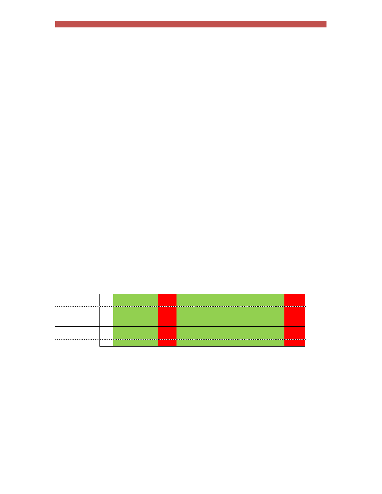
Section 14 Tutorials 81
Tutorials
The iPAK2 has a number of features that can improve weld quality, diagnostics and maintenance. Before each
tutorial:
Section 12 Configuration: ensure the Configuration parameters are set appropriately for the
application.
Section 7 Electrode management: ensure the Calibration parameters are set.
01 Testing the weld current
The current for each weld can be tested against upper and lower limits.
1. In the weld program, enable the Monitor option for each weld to be tested.
2. Set the Low limit and High limits appropriately. The limits correspond to a percentage of the
required current.
If the weld current falls outside the limits, iPAK2 will signal a weld fault.
Current
High limit
Target
Low limit
Spots
Pass Fault Pass Fault
Page 82
Section 14 Tutorials 82
02 Changing the force during a weld
iPAK2 can change the force during a weld when the force profile option is enabled. The force can be changed at
the beginning of any interval. The force output corresponds to the analog output on connector X5.
Parameter Units Range Description
Squeeze1 kN/lbf variable Force used from the start of the Squeeze interval
Pre-heat1 kN/lbf variable Force used from the start the Pre-heat interval
Cool11 kN/lbf variable Force used from the start the Cool1 interval
Upslope1 kN/lbf variable Force used from the start the Upslope interval
Main heat kN/lbf variable Force used from the start of the Main heat interval
Cool2 kN/lbf variable Force used from the start of the Cool2 interval
Downslope1 kN/lbf variable Force used from the start of the Downslope interval
Post-heat1 kN/lbf variable Force used from the start the Post-heat interval
Hold1 kN/lbf variable Force used from the start the Hold interval
1
If the force profile option is disabled the Main heat force is used for the duration of the weld.
1. In the weld program, enable the force profile option.
2. In the Force parameters, set the values for each interval. The change takes place at the start of
each interval and the force for each interval can be tested against limits.
Page 83
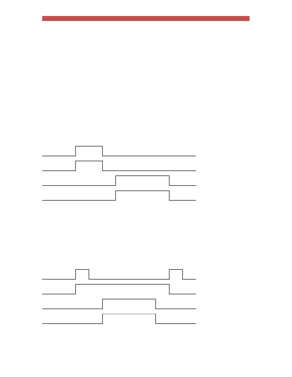
Section 14 Tutorials 83
03 Using the Retract functions
The Retract function allows the welding head to open in two stages.
The fully open position allows the work piece to be positioned between the electrodes.
The middle position allows the electrodes to close onto the work piece in order to weld.
iPAK2 has four Retract modes that can be used depending on the application. The mode is selected in the
Configuration settings.
Simple
When the Retract Input is switched off, the High Lift Air Valve switches off and the electrodes close to
the mid position. Welding can proceed in this case.
When the Retract Input is switched on, the High Lift Air Valve switches on and the electrodes open fully.
Welding will not proceed in this case.
Retract input
HAV output
Start input
WAV output
Hi-lift +
A pulse on the Retract Input causes the High Lift Air Valve to switch on and close the electrodes to the
mid position. Welding can proceed in this case.
Whilst the High Lift Air Valve is on, a pulse on the Retract Input causes the valve to switch off and the
electrodes go to the fully open position. Welding will not proceed in this case.
Retract input
HAV output
Start input
WAV output
Page 84
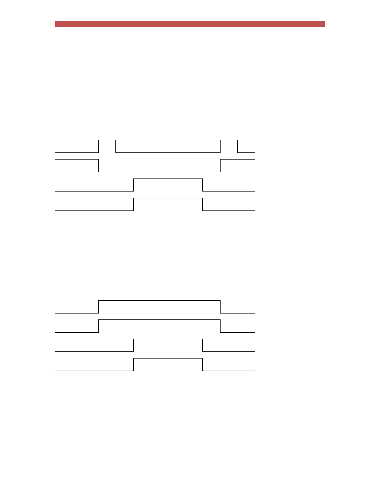
Section 14 Tutorials 84
Hi-lift -
A pulse on the Retract Input causes the High Lift Air Valve to switch off and close the electrodes to the
mid position. Welding can proceed in this case.
Whilst the High Lift Air Valve is off, a pulse on the Retract Input causes the valve to switch on and the
electrodes go to the fully open position. Welding will not proceed in this case.
Retract input
HAV output
Start input
WAV output
Maintained
When the Retract Input is switched on, the High Lift Air Valve switches on and the electrodes close to
the mid position. Welding can proceed in this case.
When the Retract Input is switched off, the High Lift Air Valve switches off and the electrodes open fully.
Welding will not proceed in this case.
Retract input
HAV output
Start input
WAV output
Page 85
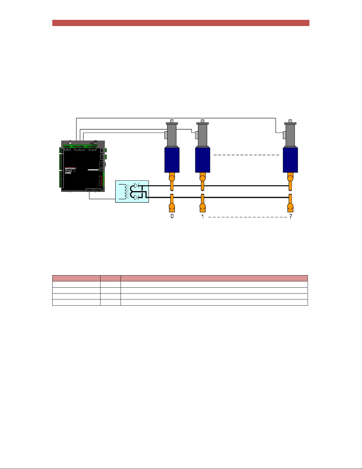
Section 14 Tutorials 85
04 Using the valves to control a multi-head machine
iPAK2 can be used with welding machines that have multiple welding heads. By assigning one of the iPAK2s AV
outputs, each head can be operated individually.
The weld air valve or WAV output is determined by the weld program.
1. In the weld program, use the Valve parameters to select an output that will be used as the WAV
2. The WAV will become active when the Start input is active and will remain active until the end of the
weld sequence unless programmed otherwise.
For example:
Program WAV Description
0 AV1 Program 0 uses AV1 as the WAV
1 AV2 Program 1 uses AV2 as the WAV
2 AV3 Program 2 uses AV3 as the WAV
3 AV4 Program 3 uses AV4 as the WAV
Page 86
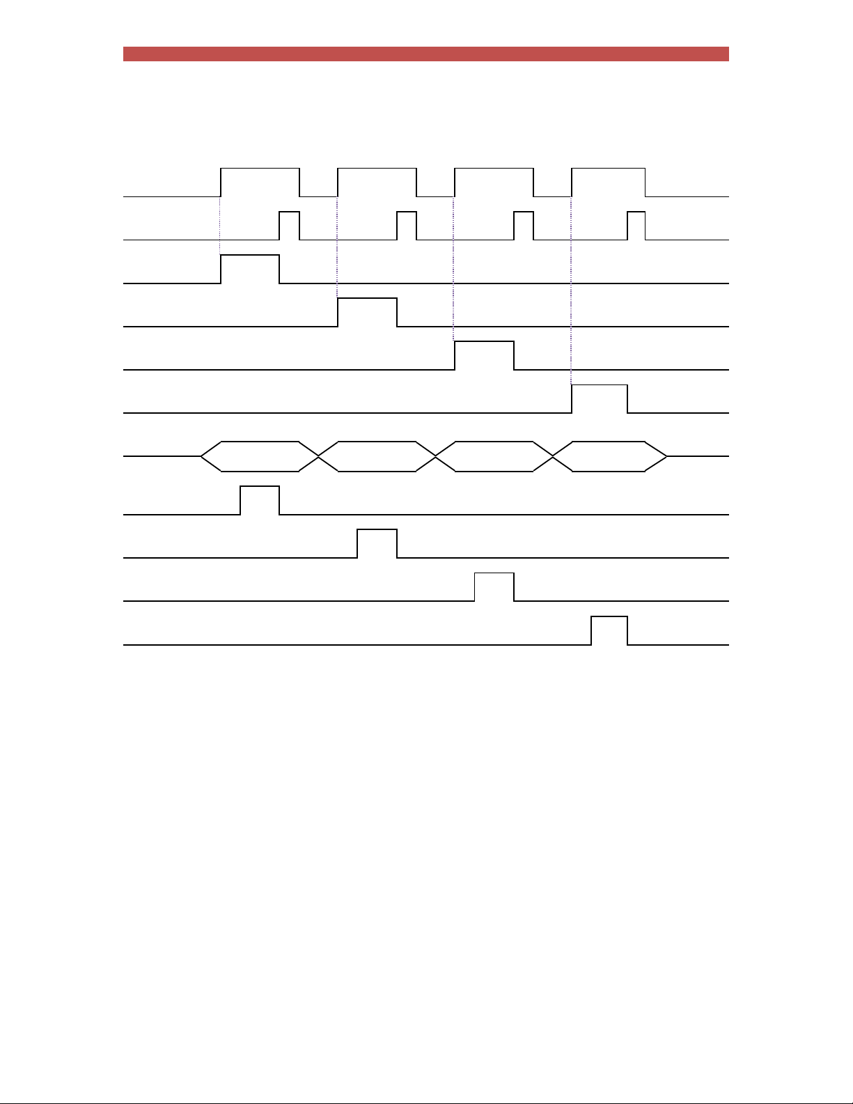
Section 14 Tutorials 86
The diagram shows the operation in multi-gun mode:
Start input
EOS output
AV1 output
AV2 output
AV3 output
AV4 output
Program
select
Current
(Program 0)
Current
(Program 1)
Current
(Program 2)
Current
(Program 3)
#0
#1 #2 #3
Page 87
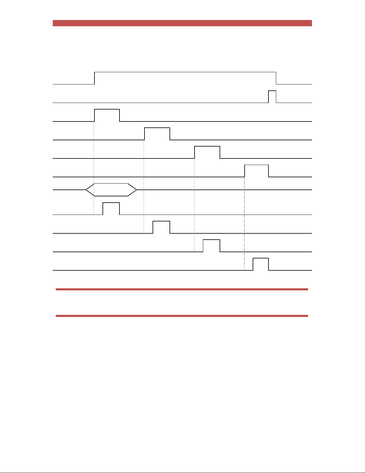
Section 14 Tutorials 87
The operation is similar when the programs are linked together in multi-gun cascade mode:
Start input
EOS output
AV1 output
AV2 output
AV3 output
AV4 output
Program
select
Current
( Program 0)
Current
( Program 1)
Current
( Program 2)
Current
( Program 3)
First
program #
The program select inputs select the first program in the cascade (0 in this example).
Page 88
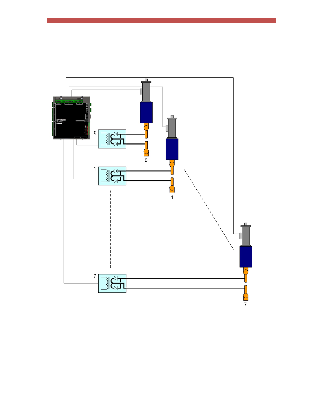
Section 14 Tutorials 88
05 Controlling a multiwelder
A multiwelder can use different transformers for each welding head.
The welding heads can be controlled as described in the previous tutorial.
1. Choose the transformers that will be assigned to the electrodes. The procedure is described in Section
10 Multiwelding.
2. Choose the weld programs that will be using the electrodes.
Page 89
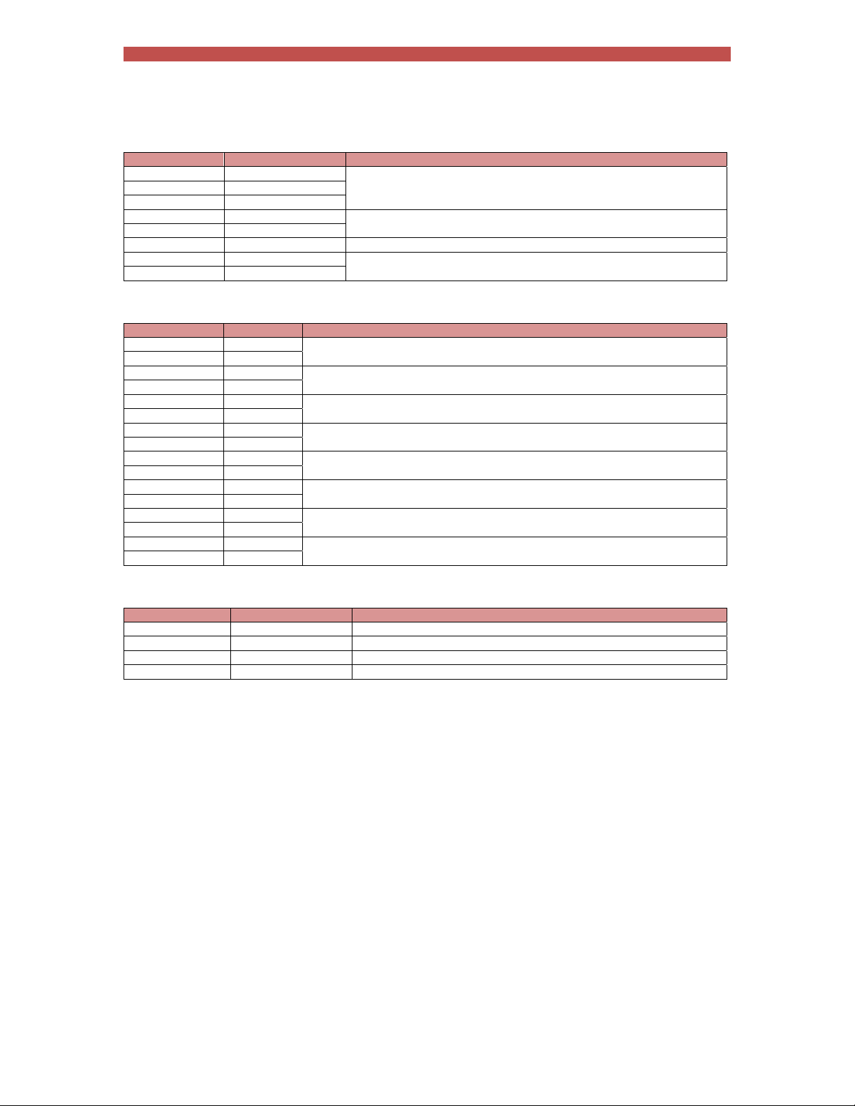
Section 14 Tutorials 89
For example:
Electrode Transformer Description
0 0
1 0
2 0
3 1
4 1
5 2 Electrode 5 is assigned to transformer 2
6 3
7 3
The electrodes can then be assigned to weld programs:
Weld program Electrode Description
0 0
1 0
2 1
3 1
4 2
5 2
6 3
7 3
8 4
9 4
10 5
11 5
12 6
13 6
14 7
15 7
Weld programs 0 and 1 are assigned to Electrode 0
Weld programs 2 and 3 are assigned to Electrode 1
Weld programs 4 and 5 are assigned to Electrode 2
Weld programs 6 and 7 are assigned to Electrode 3
Weld programs 8 and 9 are assigned to Electrode 4
Weld programs 10 and 11 are assigned to Electrode 5
Weld programs 12 and 13 are assigned to Electrode 6
Weld programs 14 and 15 are assigned to Electrode 7
Electrodes 0, 1 and 2 are assigned to transformer 0
Electrodes 3 and 4 are assigned to transformer 1
Electrodes 6 and 7 are assigned to transformer 3
By implication the transformers are used as follows:
Transformer Weld programs Description
0 0, 1, 2, 3, 4, 5 Transformer 0 is used by weld programs 0, 1, 2, 3, 4, and 5
1 6, 7, 8, 9 Transformer 1 is used by weld programs 6, 7, 8 and 9
2 10, 11 Transformer 2 is used by weld programs 10 and 11
3 12, 13, 14,15 Transformer 3 is used by weld programs 12, 13, 14 and 15
Page 90
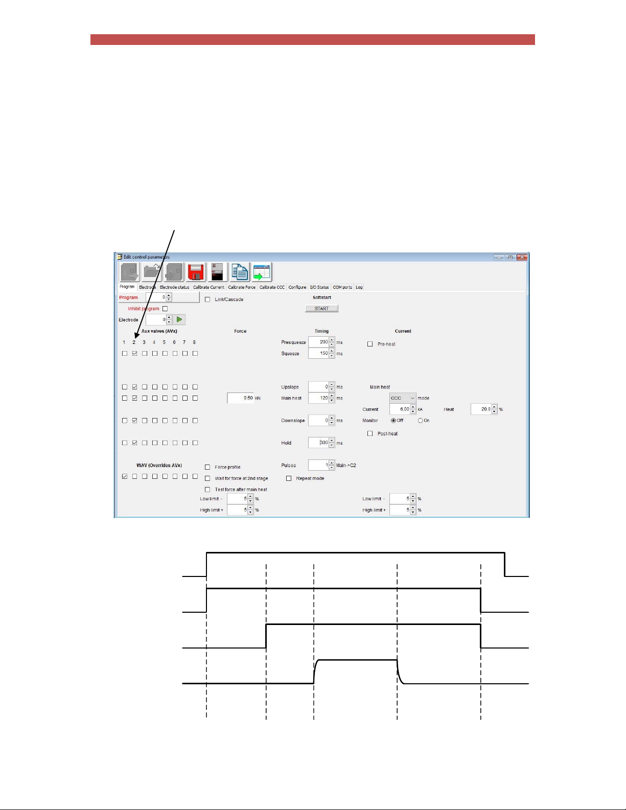
Section 14 Tutorials 90
06
Controlling an ‘Air over Oil’ system
An ‘Air over Oil’ system (also referred to as OHMA) uses compressed air to open and close the electrodes plus a
hydraulic intensifier to apply the weld force. This type of system can easily be controlled by the iPAK2 by making
use of the programmable AUX valves feature.
1. Connect the air solenoid (ADVANCE) to the AV1(SV1) output (or whichever output you have
programmed to provide the WAV function).
2. Connect the hydraulic solenoid (INTENSIFY) to the AV2(SV2) output (or whichever AUX output you
wish to use).
3. In your welding schedule(s), set the Presqueeze time to suit the gun closure, and the Squeeze t ime to
apply the force pre-weld. Now program the AUX valve chosen in step 2 to come on during all of the
intervals which you are using (e.g. Squeeze, Main heat, Hold).
START
ADVANCE
INTENSIFY
CURRENT
Presqueeze Squeeze Mainheat Hold
Page 91

Section 14 Tutorials 91
07
Resetting faults
Fault conditions and error messages can be reset in several ways.
WSP3
LOWMAINCURRENT
‐‐0aprog0
‐‐10.1ka5.80kn
From the Status screen press
‐‐0a~30.5%
NetFlash
Use to select the Metrics window then select the
reset button
Discrete input
Input Pin number Description
Reset fault P2.15 This input resets the Fault output and clears the status
The discrete I/O is described in Section 4 Discrete I/O.
messages. Only momentary application is required
(minimum time 40ms).
Bus input
Input Channel Address Description
Reset fault Bit 6 %QX0.6 This input resets the Fault output and clears the status
The bus I/O is described in Section 5 MODBUS I/O.
messages. Only momentary application is required
(minimum time 40ms).
Page 92
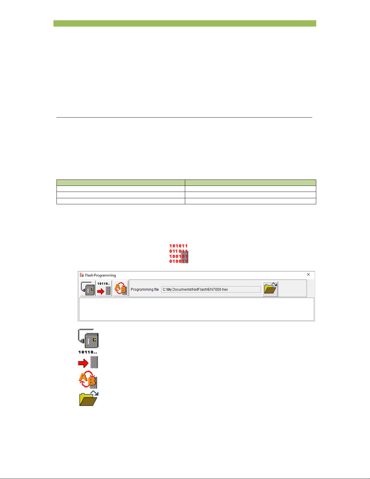
Section 15 Appendix 92
Appendix
Updating the firmware
The functionality of iPAK2 is determined by firmware stored in reprogrammable memory. iPAK2 has three
memories:
Memory Description
A Memory A
B Memory B
BIOS BIOS memory
The firmware can be transferred to one or more of the memories and then activated when iPAK2 starts. In this
way it is possible to retain different firmwares and activate them without having to reprogram iPAK2. When new
features become available NetFlash is used to update the firmware.
Initialise NetFlash and select the target iPAK2 as described in Section 13 Programming.
Select the Flash Programming tool . The following screen is shown:
Connect to the iPAK2
Start transfer to the iPAK2
Change the active memory
Select the flash file
Page 93
Section 15 Appendix 93
Select the flash file . This will be a file with a .hex extension supplied by ENTRON UK.
Select connect to the iPAK2 . NetFlash will connect to the target control and report the
current firmware status.
Select start transfer to the iPAK2 . Select a memory to re-program and NetFlash will
transfer the flash file to the iPAK2.
If required, select change the active memory . NetFlash will mark the selected memory for
activation. When iPAK2 restarts, the selected memory becomes active.
Setting the IP address
iPAK2 uses a device server for Ethernet communications on COM0 and COM1. The device server is an xPort
AR, manufactured by Lantronix www.lantronix.com
To set the IP address of the iPAK2 use Lantronix’s DeviceInstaller software
www.lantronix.com/products/deviceinstaller/
Download the documentation and Device Installer software. Install the software.
Follow the instructions in the documentation to search for all Lantronix devices on your network. Device
Installer will show the iPAK2 device server in the device list. The example shows an iPAK2/xPort AR
with a hardware address of 00-20-4A-D5-FB-7B:
Page 94
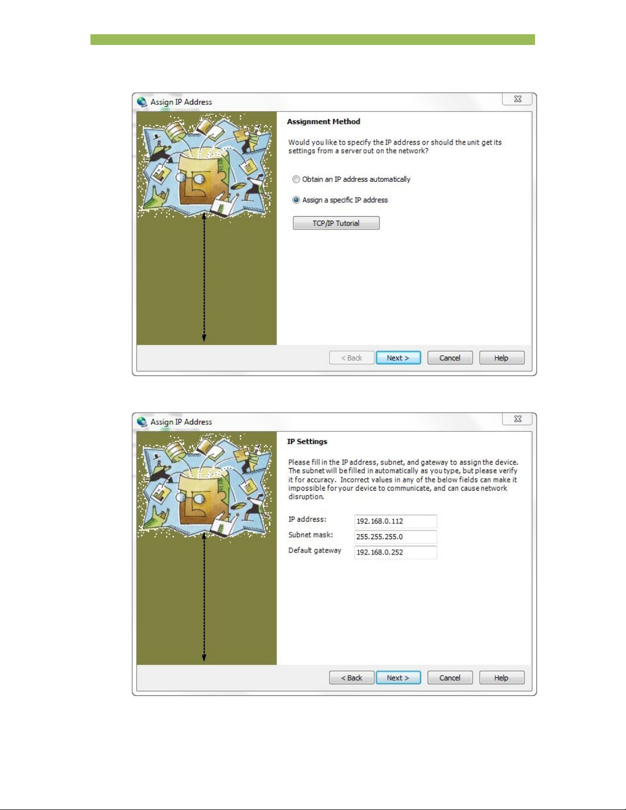
Section 15 Appendix 94
Select the iPAK2/xPort AR device then select Assign IP:
Select ‘Assign a specific IP address’ and then select Next:
Page 95
Section 15 Appendix 95
Enter the IP address, subnet mask and gateway then select Next:
Select Assign to complete the assignment. Device Installer will show the progress of the operation:
Select Finish to return to the main screen.
Page 96
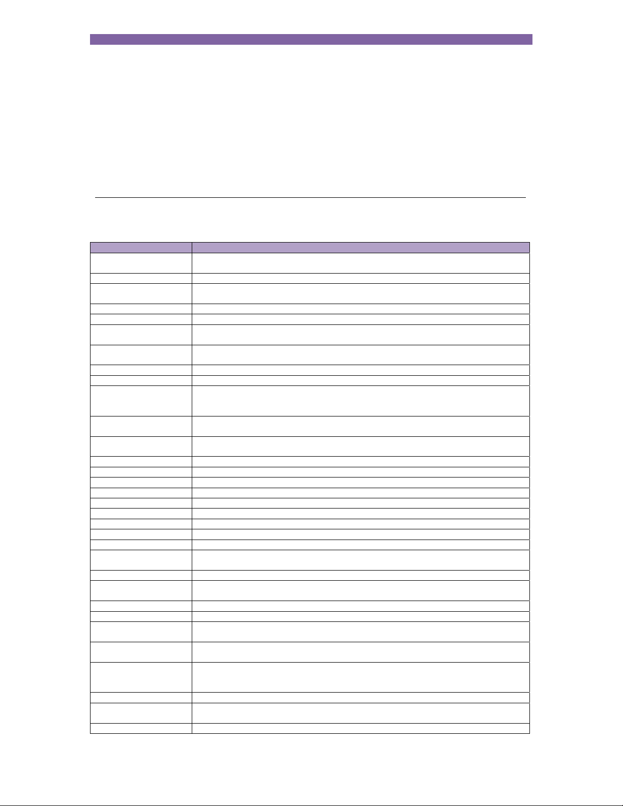
Section 16 Terminology 96
Terminology
Term Description
Constant current Closed loop control of weld current resulting in the weld current being regulated to a
CT See Current transformer.
Current transformer A coil of wire wound on a circular core. This is used to measure the current in a cable
Cool time The time between weld pulses.
Downslope A linear decrease in current from the Main heat value to a final value.
Downslope time Time taken for the welding current to decrease from the Main heat value to a final
End of sequence An output that switches on as the electrodes open on completion of a weld. The
EOS See End of sequence.
HAV Hi-lift Air Valve. See also Retract.
Heat A measure of power put into a phase angle controlled (non- constant current) weld.
Hold The time between the last application of current and the electrodes opening. This
Hold time The time period following the last weld pulse prior to the electrodes opening. This
IP address Internet Protocol address. A unique address used by devices on an Ethernet network.
Initiation signal The signal that starts the weld sequence. See also Start signal
kA Kilo amp (1000 amps).
kVA Unit of power (1000 volt amps).
mA Milliamp (1/1000 amp).
mV Millivolt (1/1000 volt).
Off time In a Repeated weld sequence this is the time between sequences.
PHA See Phase angle control.
Post-heat The application of current to prevent the weld cooling too quickly.
Pre-heat The application of current prior to welding for the purpose of burning through plating
Presqueeze The time interval in a weld sequence for the electrodes to close onto the work piece.
Primary current The current in the primary winding of the weld transformer which is the current drawn
Program select A group of inputs representing the binary value of the weld program to be used.
Proportional valve A device for regulating air-line pressure. Controlled by 0 to10 V dc signal.
Pulsations The number of times the Main heat interval is repeated during the sequence.
Retract The electrodes have two open positions: fully open to move the weld gun to and from
Retract air valve For use on a gun where the electrodes can be opened and closed in two stages. This
2nd stage A signal required to allow the weld sequence to proceed.
Secondary current The current in the secondary winding of the weld transformer which is the weld
Squeeze The time interval in a weld sequence for the electrodes to exert full welding force on
programmed value.
passing through the circular core. iPAK2 can use a CT to measure primary current.
value.
output indicates the end of the weld sequence.
The Heat relates directly to the firing angle on the mains voltage waveform.
Expressed as a percentage.
interval allows the molten material created by the weld process to solidify.
period allows the molten material to solidify.
or surface contamination.
from the mains whilst welding.
Successive applications of Main heat are separated by Cool2 time.
the work piece, and a working position for welding.
is an electrically operated valve for admitting air to the air cylinder that controls the
electrode movement.
current.
Page 97
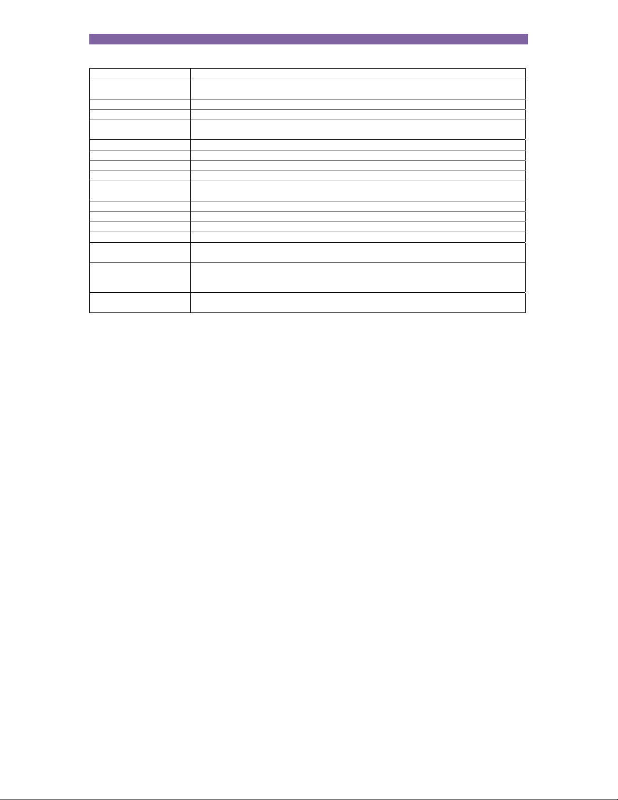
Section 16 Terminology 97
the work piece.
Squeeze time The time allowed for the welding electrodes to build up full pressure on the
Start signal The signal that starts the weld sequence.
Stepper A program of parameters required for stepping.
Stepping A technique of progressively increasing the weld current over the course of a large
Thermostat A switch device that operates at a certain temperature.
Tip dress acknowledge An input to acknowledge that the electrodes have been dressed.
Tip dress request An output to indicate that the electrodes require dressing.
Tip dressing Filing or machining worn electrodes to restore their original shape and dimensions.
Toroid A device used for sensing current in a cable. The current carrying cable must pass
Upslope A linear increase in current from an initial value to the Main heat value.
Upslope time Time taken for current to increase from an initial value to the Main heat value.
VA Volt amp
WAV See Weld air valve.
Weld air valve Electrically controlled valve for admitting air to the air cylinder responsible for forcing
Weld current High current passed from one electrode to the other, through the components being
Weld transformer Electrical component for converting mains voltage input to low voltage, high current
components to be welded.
number of welds in order to compensate for the effects of electrode wear.
through the toroid.
the weld electrodes together.
welded. The current must be large enough to generate sufficient heat to melt the
metal and produce a weld.
output.
 Loading...