

Page 1
Ditec PWR25H/35H
Automation for hinged
gates
(translation of the original instructions)
www.entrematic.com
IP2250EN
Technical Manual
Page 2

26
IP2250EN - 2016-12-02
Contents
Key
Subject Page
1. General safety precautions 27
2. Declaration of incorporation of partly completed machinery 28
2.1 Machinery Directive 28
3. Technical specifications 29
4. Standard installation 31
5. Gearmotor dimensions and references 32
6. Installation 33
6.1 Preliminary checks 33
6.2 Bracket fastening 34
6.3 Positioning usage 35
6.4 Gearmotor installation 36
6.5 Adjusting the mechanical end stops 37
6.6 Electrical connections 38
6.7 Magnetic limit switches adjustment (PWR35H only) 39
7. Routine maintenance plan 40
8. Troubleshooting 41
9. Disposal 41
Operating instructions 43
Manual release instructions 44
i
This symbol indicates instructions or notes regarding safety, to which special attention must be paid.
This symbol indicates useful information for the correct functioning of the product.
Page 3
27
IP2250EN - 2016-12-02
This installation manual is intended for qualified personnel only.
Installation, electrical connections and adjustments must be performed in accordance
with Good Working Methods and in compliance with the present standards.
Read the instructions carefully before installing the product.
Incorrect installation could be dangerous.
Before installing the product, make sure it is in perfect condition.
Before installing the motorisation device, make all the necessary structural modifications to create safety clearance and to guard or isolate all the crushing, shearing,
trapping and general hazardous areas.
Make sure the existing structure is up to standard in terms of strength and stability.
The motorisation device manufacturer is not responsible for failure to observe Good
Working Methods when building the frames to be motorised, or for any deformations
during use.
The safety devices (photocells, safety edges, emergency stops, etc.) must be installed
taking into account the applicable laws and directives, Good Working Methods, installation premises, system operating logic and the forces developed by the motorized gate.
The safety devices must protect the crushing, shearing, trapping and general hazardous
areas of the motorised door.
Display the signs required by law to identify hazardous areas.
Each installation must bear a visible indication of the data identifying the motor-
ized gate.
When requested, connect the motorized gate to an effective earthing system that
complies with current safety standards.
During installation, maintenance and repair operations, cut off the power supply before
opening the cover to access the electrical parts.
The automation protection casing must be removed by qualified personnel only.
The manufacturer of the motorisation device declines all responsibilit y if compo-
nent parts not compatible with safe and correct operation are fitted.
Only use original spare parts when repairing or replacing products.
The installer must supply all information on the automatic, manual and emergency operation of the motorised gate, and must provide the user with the operating instructions
.
1. General safety precautions
Failure to respect the information given in this manual
may cause personal injury or damage to the device.
Keep these instructions for future reference
Page 4

28
IP2250EN - 2016-12-02
2. Declaration of incorporation of partly completed machinery
(Directive 2006/42/EC, Annex II-B)
The manufacturer Entrematic Group AB, with headquarters in Lodjursgatan 10, SE-261 44
Landskrona, Sweden, declares that the Ditec PWR25H / PWR35H automation for swing gates:
- is designed to be installed on a manual gate to form a machine pursuant to Directive 2006/42/
EC. The manufacturer of the motorised gate must declare conformity with Directive 2006/42/
EC (annex II-A) prior to initial machine start-up;
- complies with the applicable essential safety requirements indicated in Annex I, Chapter 1 of
the Directive 2006/42/EC;
- complies with the Electromagnetic Compatibility Directive 2014/30/EU;
- complies with the RED Directive 2014/53/EU;
- the technical documentation complies with Annex VII-B of the Directive 2006/42/EC;
- the technical documentation is managed by the Technical Office of Entrematic Italy (with
headquarters in Largo U. Boccioni 1 – 21040 Origgio (VA) – ITALY) and is available upon request,
sending an e-mail to ditec@entrematic.com ;
- a copy of the technical documentation will be given to competent national authorities, following
a suitably justified request.
Landskrona, 01-07-2016 Matteo Fino
(Chairman)
2.1 Machinery Directive
Pursuant to the Machinery Directive (2006/42/EC), the installer who motorises a door or gate has
the same obligations as the manufacturer of machinery and as such must:
- prepare the technical data sheet which must contain the documents indicated in Annex V of the
Machinery Directive;
(the technical data sheet must be kept and placed at the disposal of competent national author-
ities for at least ten years from the date of manufacture of the motorised door or gate);
- draw up the EC Declaration of Conformity in accordance with Annex II-A of the Machinery
Directive and deliver it to the customer;
- affix the EC marking on the motorised door or gate, in accordance with point 1.7.3 of Annex I of
the Machinery Directive.
Page 5
29
IP2250EN - 2016-12-02
3. Technical specifications
PWR25H PWR35H
Power 24V
Maximum
power
5A 5.5A
Absorbed power 55W nom. / 120W max 65W nom. / 132W max
Maximum thrust 2000 N 3000 N
Maximum stroke 350mm 450mm
Opening time 10÷60 s/90° 14÷80 s/90°
Intermittence
80 cycles/day [max]
30 consecutive cycles at 20°C
max 150 cycles/day [max]
50 consecutive cycles at 20°C
Duration
From 90,000 to 150,000 cycles based on
the conditions indicated in table 3.1 (see
the durability graphs of the product)
From 120,000 to 300,000 cycles based on
the conditions indicated in table 3.1 (see
the durability graphs of the product)
Operating temperature -20°C / +55°C (-35°C + 55°C with NIO active)
Degree of protection IP44 IP44
Dimensions (mm) 820 x 100 x 107 h 970 x 100 x 107 h
Weight (Kg) 7.8 9
Tab. 3.0
Graph 3.0
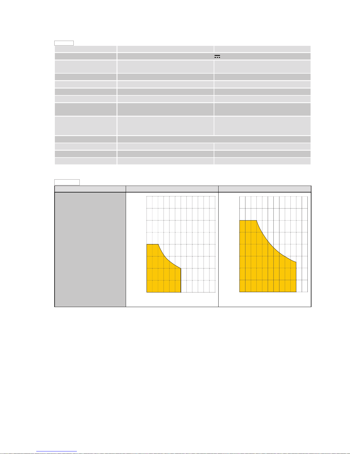
WARNING: To prevent burglary, the use of an electric lock is recommended with wings longer
than 2.3m.
PWR25H PWR35H
Usage limits
(gate wing weight and length)
0
1
100
200
300
400
500
600
700
800
23
(m)
(Kg)
4
1
0
100
200
300
400
500
600
700
800
23
(m)
(Kg)
4
Page 6
30
IP2250EN - 2016-12-02
PWR25H PWR35H
Durability of the product
0
102030
405060
70
80
90
100
0
10.000
indice di gravosità
20.000
30.000
40.000
50.000
60.000
70.000
80.000
90.000
100.000
110.000
120.000
130.000
140.000
150.000
cicli
0
102030
405060
70
80
90
100
0
20.000
indice di gravosità
40.000
60.000
80.000
100.000
120.000
140.000
160.000
180.000
200.000
220.000
240.000
260.000
280.000
300.000
cicli
PWR25H PWR35H
0
102030
405060
70
80
90
100
0
10.000
indice di gravosità
20.000
30.000
40.000
50.000
60.000
70.000
80.000
90.000
100.000
110.000
120.000
130.000
140.000
150.000
cicli
0
102030
405060
70
80
90
100
0
20.000
indice di gravosità
40.000
60.000
80.000
100.000
120.000
140.000
160.000
180.000
200.000
220.000
240.000
260.000
280.000
300.000
cicli
Severity index
PWR25H PWR35H
Wing weight
>150Kg 10 >200Kg 20 >300Kg 30 10
>400Kg - 20
>500Kg - 30
Wing width
>2m 20 10
>3m - 20
Solid wing 15
Windy area 15
Speed setting VA/VC/PO/PC over the default values 10
Force setting R1/R2 over the default values 10
Tab. 3.1Tab. 3.2
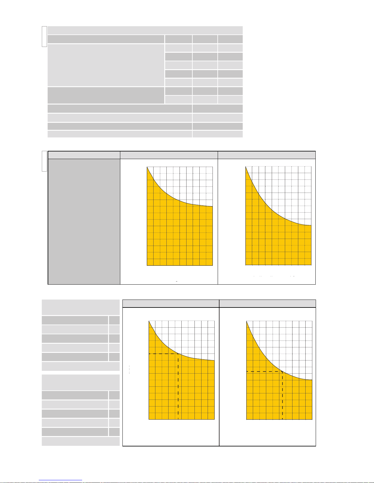
Two examples of the operator durability calculation are shown below:
The durability of the
product is influenced by
the severity index:
with reference to Tab. 3.1,
according to the type of
piston, the weight and
the width of the wing
and the use conditions,
different corrective factors were estimated, the
sum of which influence
the operator durability
(see Tab. 3.2).
Example of the duration
calculation for PWR25H
Wing weight >150 Kg 10
Wing width >2m 20
R1/R2>default 0
Windy area 15
Total severity index 45
Estimated duration 100,000 cycles
Example of the duration
calculation for PWR35H
Wing weight >300 Kg 10
Wing width >3m 20
R1/R2>default 10
Windy area 15
Total severity index 55
Estimated duration 148,000 cycles
Severity index
Severity index
cycles
cycles
Severity index Severity index
cycles
cycles
Page 7
31
IP2250EN - 2016-12-02
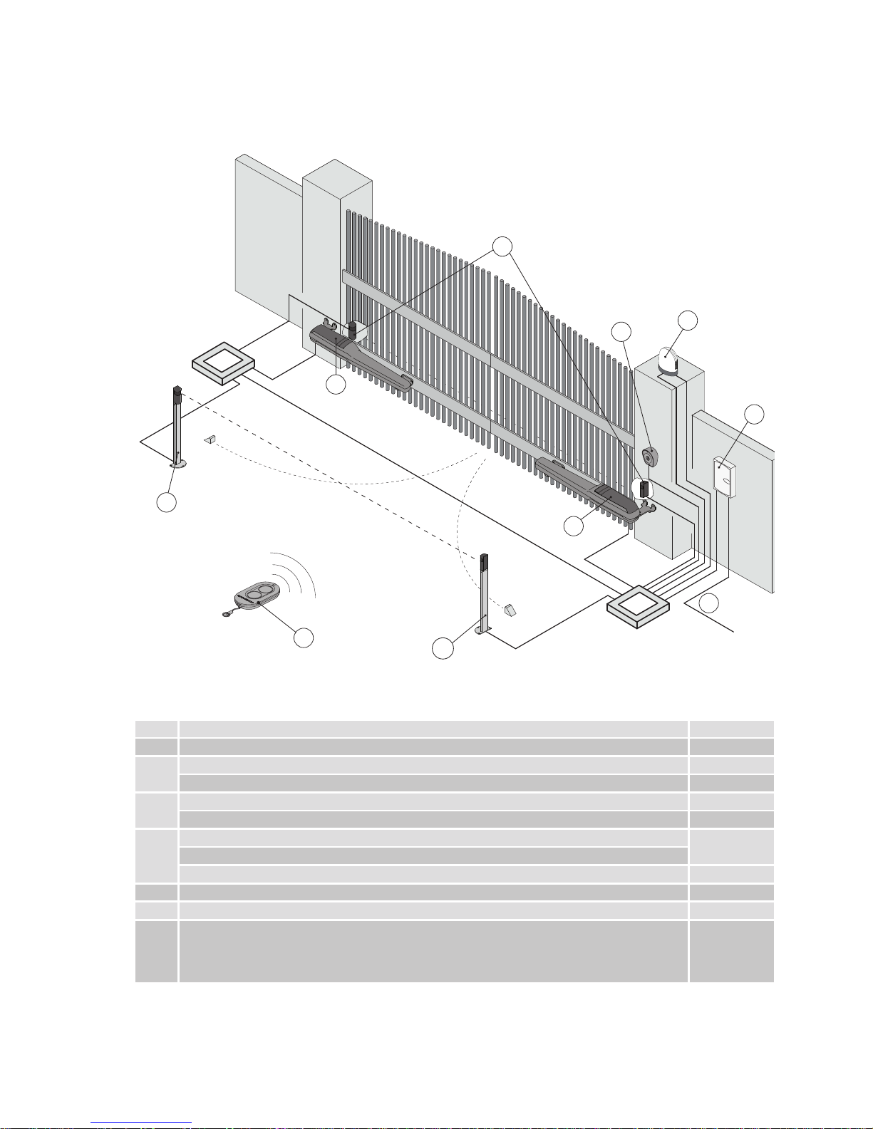
4. Standard installation
Ref. Description Cable
1 Transmitter /
2
Flashing light 2 x 1 mm²
Antenna (integrated into the flashing light) coaxial 58 Ω
3
Key selector switch 4 x 0.5 mm²
Digital combination wireless keypad /
4
Actuator PWR25H
2 x 1.5 mm²
Actuator PWR35H
Actuator PWR35H with magnetic limit switches 3 x 1.5 mm²
5 Photocells 4 x 0.5 mm²
6 Control panel 3G x 1.5 mm²
A
Connect the power supply to a type-approved omnipolar switch, with a contact opening
distance of at least 3mm (not supplied).
The connection to the mains must follow an independent path, separate from the
connections to the control and safety devices.
1
4
6
A
3
2
5
5
4
5
Page 8

32
IP2250EN - 2016-12-02
5. Gearmotor dimensions and references
Ref. Description
7 Rear cover
8 Release lock hatch
9 Cover fastening screw
10 Release key
11 Release pin
12 Front cover
107100
LT
R
8
11
9
10
7
8
12
11
7
9
10
Model L R
PWR25H 820 350
PWR35H 970 450
PWR25H
PWR35H
Fig. 5.1
Fig. 5.2
Page 9

33
IP2250EN - 2016-12-02
6.1 Preliminary checks
6. Installation
The declared operating and performance features can only be guaranteed with the use of ENTREMATIC accessories and safety devices.
Unless otherwise specified, all measurements are expressed in mm.
Check that the structure of the gate is sturdy and that the hinges are lubricated and function smoothly.
If possible, provide an opening and closing stop, otherwise use the integrated mechanical stops
and/or the electric limit switch (optional) if available. The mechanical parts must be in accordance
with the provisions of the EN12604 standard.
The installation measurements indicated in the table allow to choose the values of [A] and [B] on
the basis of the desired opening angle and in relation to the on site spaces and overall dimensions.
Increasing measurement [A], you reduce the opening approach speed.
Reducing measurement [B], you increase the degrees of gate opening.
Measurements [A] and [B] must, however, be compatible with the effective stroke of the piston.
A
P
D
E
L
B
S
C
min 60 con apertura a 90°
ABCSDELP min
PWR25H
90 160 50 110 95°
90 700
110
110 160 50 110 100° 120
150 130 50 80 110° 160
130 150 70 80 90° 140
110 180 100 80 90° 120
100 190 110 80 90° 110
PWR35H
90 190 50 140 95°
110 850
100
130 190 50 140 100° 140
150 190 50 140 110° 160
130 180 70 110 90° 140
130 210 100 110 90° 140
110 260 150 110 90° 120
100 280 200 80 90° 110
Tab. 6.1
i
The fixing point of the automation varies depending on the space available and the gate to
be automated, therefore it is up to the installer to choose each time the best solution to
ensure the correct operation of the system.
min. 60 with 90° opening
Page 10

34
IP2250EN - 2016-12-02
After choosing the most suitable fastening point for the front bracket [14] to the gate wing, to determine the height position, proceed with the sizing, positioning and fixing of the rear bracket [13].
If necessary, shorten the rear bracket [13] following measurement (S) in Tab. 6.1.
- Once you have fastened the rear bracket [13] following the measurements indicated on page
10, fasten the front bracket [14] to the gate.
- With the gate completely closed, position the front bracket [14], in accordance with measurement (L). Check that the front bracket [13] and rear bracket [14] are properly levelled as
shown in the following figures and fasten the front bracket [13] to the gate.
NB: If necessary, the front bracket [14] can be rotated and fixed as shown in figures [B], in this
way the operator position will be higher by about 40 mm.
6.2 Bracket fastening
L
13
43
14
L
13
87
14
PWR25H
2xØ9
90
38
112
70
Ø17,2
90
50
155
72
80 (S)
110 (S)
100
140 (S)
70
3xØ9
3xØ14
A
B
i
Configuration [A] is the one recommended for a greater mechanical resistance.
Page 11

35
IP2250EN - 2016-12-02
The positioning of the brackets can be greatly simplified by using the positioning template (optional
accessory), which allows to establish with certainty the fixing positions and distances of a bracket
with respect to the other during installation. In this way positioning errors and incorrect alignment
of the fixing holes are avoided thanks to the level integrated in the template.
The installation template is compatible with all pistons of the PWR, Obbi and Luxo series.
6.3 Positioning template usage
4xØ9
49
110
132
80
47
100
Ø17,2
50
155
72
80 (S)
110 (S)
100
140 (S)
70
3xØ9
3xØ14
PWR35H
L
13
43
14
L
13
87
14
A
B
Page 12

36
IP2250EN - 2016-12-02
6.4 Gearmotor installation
• Open the release lock hatch [8], loosen the screw [9] and remove the rear cover [7].
• Release the piston by inserting the key [10] in the appropriate pin [11] and turn it counter-clock-
wise as indicated by the arrow.
• Insert the rear bushing [18] into the hole of the rear bracket [13] and lubricate the pivot points.
• Fix the piston to the rear bracket, fully tightening the M8x45 screw [19] to nut [20].
• Open the wing manually and insert the front mounting pin [15] into the hole of the front fastening
bracket [14]; block the pin in the bracket using the washer [16] and the M8x16 screw [17] supplied.
• Moving the gate manually, check that the entire stroke takes place without interference.
8
9
7
10
13
20
11
18
19
15
14
16
17
Page 13

37
IP2250EN - 2016-12-02
4 mm
4 mm
180°
6.5 Adjusting the mechanical end stops
The mechanical end stops are adjusted in steps of 4mm.
Example: GATE WING STOP at stroke [R] = 340 – 344 – 348mm, etc.
If the stopping point of the gate wing does not coincide with the required position, remove the
mechanical end stop and rotate it 180° before replacing it in the toothed guide (as shown in the
figure below).
In this way, the mechanical end stops are still adjusted in 4mm steps, but at points differentiated
by 2mm.
Example: GATE WING STOP at stroke [R] = 338 – 342 – 346mm, etc.
Page 14

38
IP2250EN - 2016-12-02
6.6. Electrical connections
The PWR25H and PWR35H gear-motors can be connected to control panels LCU30 and LCU40.
To connect the automation to the control panel, proceed as follows:
• Remove the rear cover [9] as shown in paragraph 6.4;
• Fit the cable gland on the automation, securing it with the nut inserted in the hole in the casting
(Fig. 6.1 and 6.2), then insert the connecting cables (Fig. 6.3);
• Connect the various wires as shown in the wiring diagram in Fig. 6.4;
• Secure the rear cover [9] to the gearmotor.
The electrical wiring and start-up of the gear-motors PWR25H and PWR35H are shown in the
installation manuals of control panels LCU30 and LCU40.
A flexible corrugated Ø16 pipe and related Ø20 fitting (not supplied) can be used to increase protection of the motor cable.
Fig. 6.1
Fig. 6.2
Fig. 6.3
LN
33 32
31
36 35
34
Alimentazione
230V
~ - 50/60 Hz
24V 24V
Motoriduttore 24V con
ritardo in apertura
33/36 32/35 31/34
Motoriduttore 24V con
Quadro elettronico
ritardo in chiusura
33/36 32/35 31/34
M2
M1
M1
M2
Fig. 6.4
24V gearmotor with
opening delay
24V gearmotor with
closing delay
Control Panel
Power
Page 15

39
IP2250EN - 2016-12-02
• Loosen the sensor support screws, adjust the opening and closing position of the sensors using
the notches as a guide, and tighten the screws.
• Secure the cables to the appropriate supports using cable straps.
See the instructions attached to the limit switch kit for additional information.
6.7 Magnetic limit switches adjustment (PWR35H only)
The front cover must be removed for the maintenance, adjustment and/or installation of the
magnetic limit switches:
• Loosen screw [11], slide the cover [12] forward and lift the front of it.
12
11
Fig. 6.5
Fig. 6.6
Page 16

40
IP2250EN - 2016-12-02
Perform the following operations and checks every 6 months or based on the intensity of use of
the automation.
Disconnect the 230 V~ power supply and batteries (if present):
- Clean and lubricate the gate's rotation pins, hinges and drive screws with neutral grease.
- Check the resistance of the fixing points.
- Check the electrical wiring is in good condition.
Reconnect the 230V~ power supply and batteries (if present):
- Check the power adjustment.
- Check that all commands and safety functions (photocells) are operating correctly.
- Check that the release system is working correctly.
- Test the batteries (in continuity) if present, disconnecting power and performing a few manoeuvres
in succession. Once performed, turn on the 230 V~ power supply again.
7 . Routine maintenance plan
7.2 Maintenance every 12 months or 20,000 cycles (PWR35H only)
- Lubrication of the reducer gears and motor worm screw:
insert lubricant using a manual greaser, connecting it to the specific filler valve (model NIP DIN
71412A-M6) inside the manual release compartment [Fig. 7.1].
Amount of grease to be inserted (5ml) = (8-10g).
- Lubrication of the drive screw and split nut / nut screw:
remove the plastic front cover [see par. 6.7] and spread the lubricant on the upper visible part of
the drive screw [Fig. 7.2].
Approx. amount of grease to be used (5ml) = (8-10g).
Fig. 7.1
Recommended grease: type EP1.
i
Fig. 7.2
7.1 Maintenance every 6 months or 10,000 cycles
Page 17

41
IP2250EN - 2016-12-02
The packaging components (cardboard, plastic, etc.) should be disposed through the
separate collection for recycling. Before proceeding however, check the local regulations
regarding disposal.
The packaging materials should not be discarded in the environment or left within reach of
children, as they are a potential source of danger.
To dispose of electrical and electronic equipment, batteries and storage cells correctly,
users must take the product to special "recycling centres" provided by the municipal authorities
for disposal according to the methods envisaged by current legislation.
NB: for spare parts, see the spares price list.
8 . Troubleshooting
i
Problem Possible cause Operation
The gate doesn't
open or close.
No power supply. Check that the mains power supply is
present.
Gearmotor released. See release instructions.
Photocells interrupted. Check that the photocells are clean and
operating correctly.
Permanent stop command. Check the stop command or control
panel.
Faulty selector. Check the selector or control panel.
Faulty remote control Check the condition of the batteries.
Electric lock not working Check the positioning and proper oper-
ation of the lock.
The gate opens but
doesn't close.
Photocells interrupted. Check that the photocells are clean and
operating correctly.
9 . Disposal
Page 18

42
IP2250EN - 2016-12-02
Page 19

43
IP2250EN - 2016-12-02
Operating instructions
General safety precautions
These precautions are an integral and essential part of the product and
must be supplied to the user.
Read them carefully since they contain important information on safe installation, use and maintenance.
These instructions must be kept and forwarded to all possible future users
of the system.
This product must only be used for the specific purpose for which it was
designed.
Any other use is to be considered improper and therefore dangerous. The
manufacturer cannot be held responsible for any damage caused by improper, incorrect or unreasonable use.
Avoid operating in the proximity of the hinges or moving mechanical parts.
Do not enter within the operating range of the motorised door or gate while
it is moving.
Do not obstruct the motion of the motorised door or gate, as this may cause
a dangerous situation.
The motorised door or gate may be used by children over the age of 8 and
by people with reduced physical, sensorial or mental abilities, or lack of
experience or knowledge, as long as they are properly supervised or have
been instructed in the safe use of the device and the relative hazards.
Children must be supervised to make sure they do not play with the device,
nor play/remain in the sphere of action of the motorised door or gate.
Keep remote controls and/or any other command devices out of the reach
of children, to avoid any accidental activation of the motorised door or gate.
In the event of a product fault or malfunction, turn off the power supply
switch. Do not attempt to repair or intervene directly, and contact only
qualified personnel.
Failure to comply with the above may cause a dangerous situation.
Any repairs or technical interventions must be carried out by qualified
DETACH AND DELIVER TO THE CUSTOMER
Page 20

44
IP2250EN - 2016-12-02
DETACH AND DELIVER TO THE CUSTOMER
For any problems and/or information, contact the Technical Service.
Manual release instructions
In the event of failure or lack of voltage, open the hatch (8), insert the key (10) in the pin (11) and
rotate counter-clockwise, as indicated by the arrow.
If present, release any electric lock. Manually open the gate.
Turn the key clockwise to lock the wings.
WARNING: Only lock and release the door wings when the motor is switched off.
All the rights concerning this material are the exclusive property of Entrematic Group AB.
Although the contents of this publication have been drawn up with the greatest care, Entrematic Group AB
cannot be held responsible in any way for any damage caused by mistakes or omissions. We reserve the
right to make changes without prior notice.
Copying, scanning or changing in any way is expressly forbidden unless authorised in writing by Entrematic
Group AB.
8
10
11
personnel.
Cleaning and maintenance work must not be carried out by children unless
they are supervised.
To ensure that the system works efficiently and correctly, the manufacturer’s indications must be complied with and only qualified personnel must
perform routine maintenance on the motorised door or gate. In particular,
regular checks are recommended in order to verify that the safety devices
are operating correctly.
All installation, maintenance and repair work must be documented and
made available to the user.
Only lock and release the door wings when the motor is switched off. Do not
enter within the operating range of the wing.
Page 21

45
IP2250EN - 2016-12-02
DETACH AND DELIVER TO THE CUSTOMER
Installer's stamp Operator
Date of intervention
Technician's signature
Customer's signature
Intervention performed
Page 22

IP2250EN - 2016-12-02
Entrematic Group AB
Lodjursgatan 10
SE-261 44, Landskrona
Sweden
www.entrematic.com
 Loading...