

Page 1
Sliding Door Operator
Entrematic PSL Retrofit Kit
Installation Manual
Original instructions
1018482-EMen-2.0 – Issue 2019-07-13
Page 2

© All rights in and to this material are the sole property of Entrematic Group AB. Copying, scanning, alterations or modifications are
expressly forbidden without the prior written consent of Entrematic Group AB. Rights reserved for changes without prior notice.
Backtrack information: folder:Workspace Main, version:a546, Date:2019-07-13 time:03:00:15, state: Frozen
Page 3

CONTENTS - Original instructions
51 Tools required ..........................................................................................................................................................................
62 Mechanical installation ........................................................................................................................................................
62.1 Entrematic PSL Retrofit Kit for universal bracket solutions ............................................................................................
62.1.1 Check the components and kits ..............................................................................................................................
142.1.2 I/O board and the battery installation (option) .................................................................................................
142.1.3 Fix the brackets to the backbone assembly .........................................................................................................
182.1.4 Fix the brackets to the tension wheel ....................................................................................................................
182.1.5 Fix the brackets to the belt lock (option) .............................................................................................................
192.1.6 Fix the transmission bracket to the connecting bracket .................................................................................
192.1.7 Attachment of slack reducer ....................................................................................................................................
202.1.8 General rules of the installation ..............................................................................................................................
212.1.9 List of the adapted door types .................................................................................................................................
232.1.10 Adapted door types .....................................................................................................................................................
232.1.10.1 ATS CLIXMASTER .......................................................................................................................................
242.1.10.2 ATS TSF 2100 ..............................................................................................................................................
252.1.10.3 Baumgartner Al-Profil .............................................................................................................................
262.1.10.4 Baumgartner steel ...................................................................................................................................
272.1.10.5 DORMA ES 50 ............................................................................................................................................
282.1.10.6 DORMA ES 55/60 ......................................................................................................................................
292.1.10.7 DORMA ES 70 ............................................................................................................................................
302.1.10.8 DORMA ES 90/100 ...................................................................................................................................
312.1.10.9 DORMA ES 200 ..........................................................................................................................................
322.1.10.10 ELDEBE GSX ................................................................................................................................................
332.1.10.11 EMD ...............................................................................................................................................................
342.1.10.12 EMC ...............................................................................................................................................................
352.1.10.13 Faiveley 6 .....................................................................................................................................................
362.1.10.14 Faiveley 12 ..................................................................................................................................................
372.1.10.15 Faiveley 17 ..................................................................................................................................................
382.1.10.16 GEZE ECdrive ..............................................................................................................................................
392.1.10.17 GEZE TSA 340 .............................................................................................................................................
402.1.10.18 GEZE TSA 350 N/350 W ..........................................................................................................................
412.1.10.19 GEZE TSA 360 .............................................................................................................................................
422.1.10.20 GEZE TSA 450 .............................................................................................................................................
432.1.10.21 Gilgen SLK/SLG ..........................................................................................................................................
442.1.10.22 Gilgen SLM/SLP ..........................................................................................................................................
452.1.10.23 HORTON Series 2001 ..............................................................................................................................
462.1.10.24 Manusa PA 80 ............................................................................................................................................
472.1.10.25 Manusa STK ................................................................................................................................................
482.1.10.26 Manusa Visio ..............................................................................................................................................
492.1.10.27 Portalp 2000B ............................................................................................................................................
502.1.10.28 Porte Automatiche GTS-L/-P .................................................................................................................
512.1.10.29 Porte Automatiche GTV .........................................................................................................................
522.1.10.30 Record STA7 ...............................................................................................................................................
532.1.10.31 Record STA8 ...............................................................................................................................................
542.1.10.32 Record STA9/STA10 .................................................................................................................................
552.1.10.33 Record STA11 ............................................................................................................................................
562.1.10.34 Record STA12/STA14 Steel ....................................................................................................................
572.1.10.35 Record STA12/STA14 AL .........................................................................................................................
582.1.10.36 Record STA13 ............................................................................................................................................
592.1.10.37 Record STA15 ............................................................................................................................................
602.1.10.38 Record STA16/17 ......................................................................................................................................
612.1.10.39 Record STA19 ............................................................................................................................................
622.1.10.40 Record STA20 ............................................................................................................................................
632.1.10.41 Record STA21 ............................................................................................................................................
642.1.10.42 Tormax TMP ................................................................................................................................................
652.1.10.43 Tormax TX/TM/TMX .................................................................................................................................
662.1.10.44 Tormax TEP/TXP ........................................................................................................................................
672.1.10.45 Waldoor EC .................................................................................................................................................
682.1.10.46 Waldoor UC ................................................................................................................................................
692.1.10.47 Waldoor UWS 800 ...................................................................................................................................
702.1.10.48 Waldoor UWS 2400 .................................................................................................................................
3Issue 2019-07-131018482-EMen-2.0
Page 4

712.1.10.49 Ditec VALOR (escape route) .................................................................................................................
722.1.10.50 Ditec Bis O ..................................................................................................................................................
732.1.10.51 Ditec Bis V ...................................................................................................................................................
742.2 Entrematic PSL Retrofit Kit for TORMAX iMotion 2202 ...................................................................................................
742.2.1 Check the components ..............................................................................................................................................
752.2.2 Preparing .........................................................................................................................................................................
762.2.3 I/O board and the battery installation (option) .................................................................................................
772.2.4 Fix the nuts and screws on the drive unit kit and the main control assembly .........................................
812.2.5 Fix the drive unit kit and the main control assembly .......................................................................................
822.2.6 Fix the tension wheel assembly ...............................................................................................................................
832.2.7 Fix the transmission brackets ...................................................................................................................................
842.2.8 Placement of the transmission brackets ...............................................................................................................
852.2.9 Attachment of the tooth belt ...................................................................................................................................
862.2.10 Checking and adjusting the belt tension ..............................................................................................................
872.2.11 Bi-parting operators ....................................................................................................................................................
872.2.12 Attachment of slack reducer ....................................................................................................................................
882.2.13 Install the belt lock (option) .....................................................................................................................................
892.3 Entrematic PSL Retrofit Kit for GEZE Slimdrive ...................................................................................................................
892.3.1 Check the components ..............................................................................................................................................
902.3.2 Preparing .........................................................................................................................................................................
912.3.3 Exchange the extension beams ...............................................................................................................................
922.3.4 Fix the PSU (power supply unit) and drive unit kit ............................................................................................
952.3.5 Fix the mounting plate and MCU (control unit) ................................................................................................
962.3.6 I/O board and the battery installation (option) .................................................................................................
972.3.7 Fix the tension wheel assembly ...............................................................................................................................
982.3.8 Fix the transmission brackets ...................................................................................................................................
992.3.9 Placement of the transmission brackets ...............................................................................................................
1002.3.10 Attachment of the tooth belt ...................................................................................................................................
1012.3.11 Checking and adjusting the belt tension ..............................................................................................................
1022.3.12 Bi-parting operators ....................................................................................................................................................
1022.3.13 Attachment of slack reducer ....................................................................................................................................
1032.3.14 Install the belt lock (option) .....................................................................................................................................
1042.3.15 Fix the cable bracket ....................................................................................................................................................
1052.4 Entrematic PSL Retrofit Kit for Entrematic EMSL .................................................................................................................
1052.4.1 Check the components ..............................................................................................................................................
1062.4.2 Preparing .........................................................................................................................................................................
1072.4.3 Fix the backbone assembly ........................................................................................................................................
1082.4.4 Fix the I/O board and the battery (option) ..........................................................................................................
1102.4.5 Fix the tension wheel assembly ...............................................................................................................................
1112.4.6 Fix the connector brackets ........................................................................................................................................
1122.4.7 Placement of the transmission brackets ...............................................................................................................
1132.4.8 Attachment of the tooth belt ...................................................................................................................................
1142.4.9 Checking and adjusting the belt tension ..............................................................................................................
1152.4.10 Bi-parting operators ....................................................................................................................................................
1152.4.11 Attachment of slack reducer ....................................................................................................................................
1162.5 Entrematic PSL Retrofit Kit for Entrematic EMSL-T .............................................................................................................
1162.5.1 Check the components ..............................................................................................................................................
1172.5.2 Preparing .........................................................................................................................................................................
1182.5.3 Fix the backbone assembly ........................................................................................................................................
1192.5.4 Fix the I/O board and the battery (option) ..........................................................................................................
1202.5.5 Fix the tension wheel assembly ...............................................................................................................................
1212.5.6 Fix the connector brackets (for fast door leaves) ..............................................................................................
1222.5.7 Placement of the transmission brackets (for fast door leaves) .....................................................................
1232.5.8 Attachment of the tooth belt (for fast door leaves) .........................................................................................
1242.5.9 Checking and adjusting the belt tension (for fast door leaves) ....................................................................
1252.5.10 Bi-parting operators (for fast door leaves) ..........................................................................................................
1252.5.11 Attachment of slack reducer ....................................................................................................................................
1018482-EMen-2.0Issue 2019-07-134
Page 5

1 Tools required
• Allen key 6 mm with spherical tip
• Torx (T10 and T20)
• Phillips screw driver
• Multi/Wire cutter
• Spanner 10mm
• Tape measuring tool
1 Tools required
5Issue 2019-07-131018482-EMen-2.0
Page 6

2 Mechanical installation
2 Mechanical installation
2.1 Entrematic PSL Retrofit Kit for universal bracket solutions
Note! Following are the common steps for connecting components, please refer to cross-view for
each adapted door type.
2.1.1 Check the components and kits
Check the components (Universal)
Screw: ISO 14583 (MRT-TT) M6x10 FZB 8.84
Screw: DIN 6921 (M6SF) M6x8 FZB 8.811
Backbone assembly12
Slack reducer (Not needed if belt lock
13
equipped)
Washer: ISO 7089 (BRB) 6.4x12x1.5 FZB14
Tension wheel assembly15
Tooth belt18
Belt clamp20
Connecting bracket24
Transmission bracket26
Mounting bracket28
1018482-EMen-2.0Issue 2019-07-136
Page 7
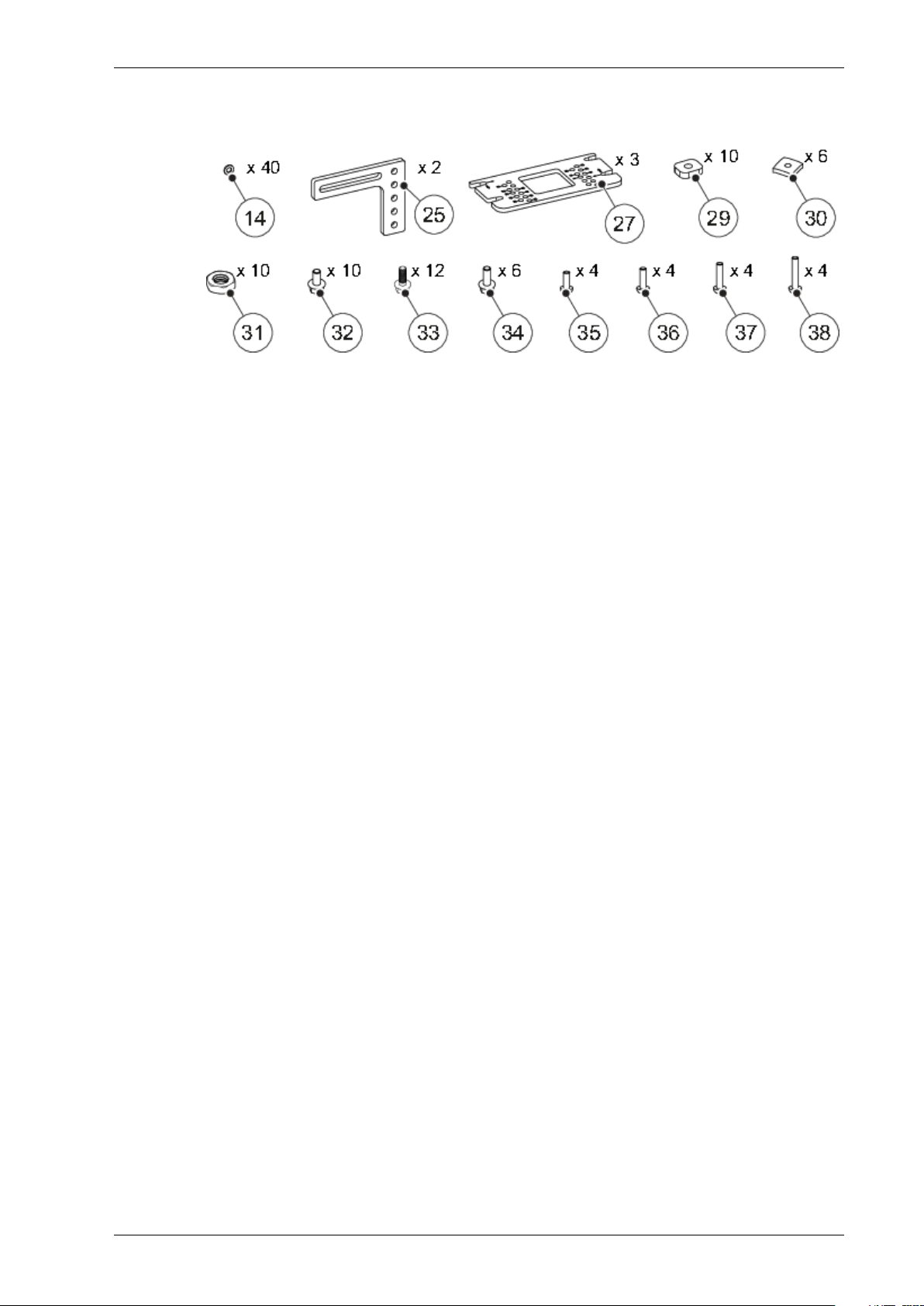
Check B1 kit
2 Mechanical installation
Washer: ISO 7089 (BRB) 6.4x12x1.5 FZB14
Bracket 125
Mounting plate27
Square nut: M629
Nut: M630
Nut: ISO 4035 (ML6M) M6 FZB31
Screw: DIN 6921 (M6SF) M6x12 FZB 8.832
Screw: DIN 6921 (M6SF) M6x14 FZB 8.833
Screw: DIN 6921 (M6SF) M6x16 FZB 8.834
Screw: ISO 14583 (MRT-TT) M6x16 FZB 8.835
Screw: ISO 14583 (MRT-TT) M6x20 FZB 8.836
Screw: ISO 14583 (MRT-TT) M6x25 FZB 8.837
Screw: ISO 14583 (MRT-TT) M6x35 FZB 8.838
7Issue 2019-07-131018482-EMen-2.0
Page 8
2 Mechanical installation
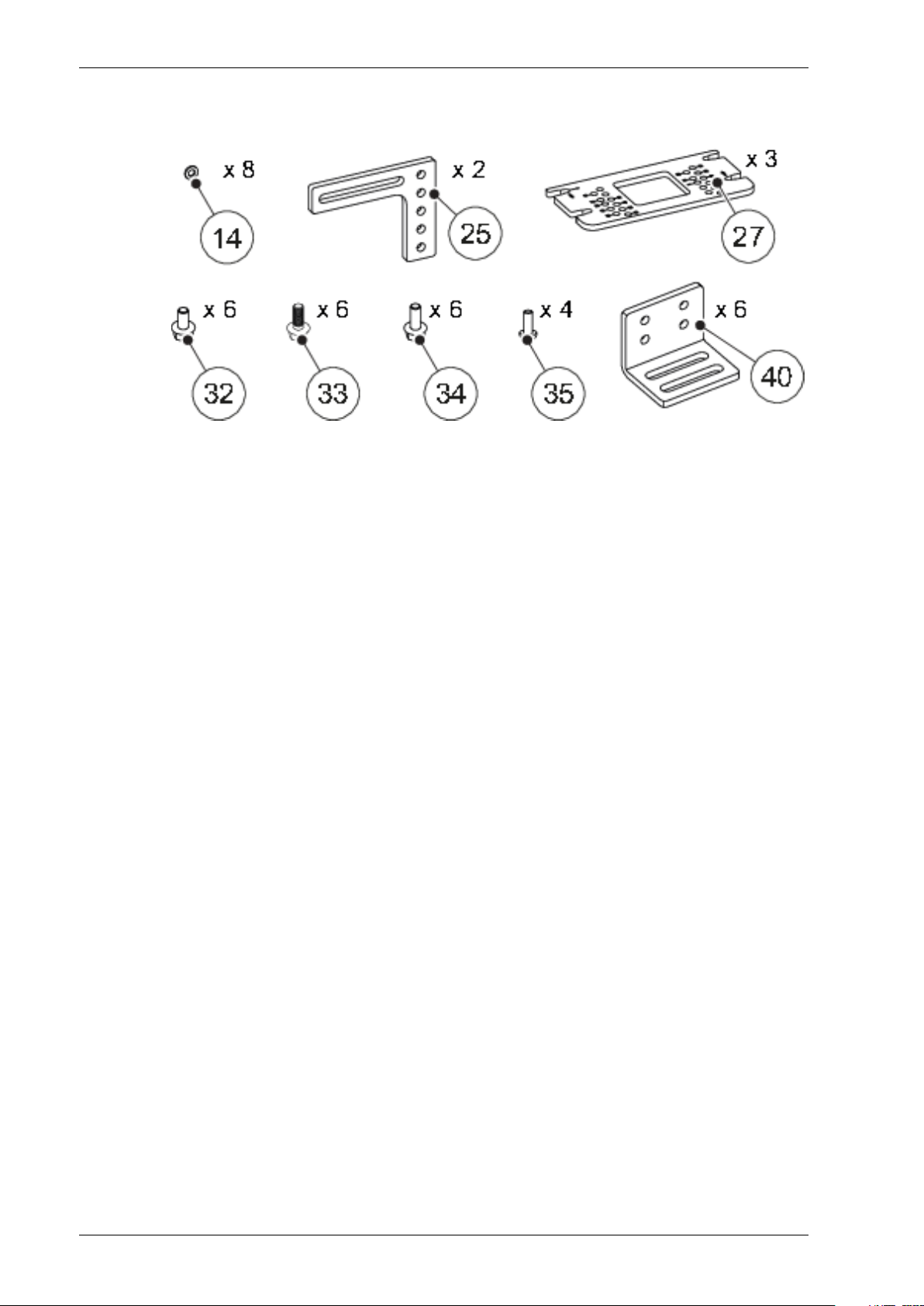
Check B2 kit
Washer: ISO 7089 (BRB) 6.4x12x1.5 FZB14
Bracket 125
Mounting plate27
Screw: DIN 6921 (M6SF) M6x12 FZB 8.832
Screw: DIN 6921 (M6SF) M6x14 FZB 8.833
Screw: DIN 6921 (M6SF) M6x16 FZB 8.834
Screw: ISO 14583 (MRT-TT) M6x16 FZB 8.835
Bracket 240
1018482-EMen-2.0Issue 2019-07-138
Page 9
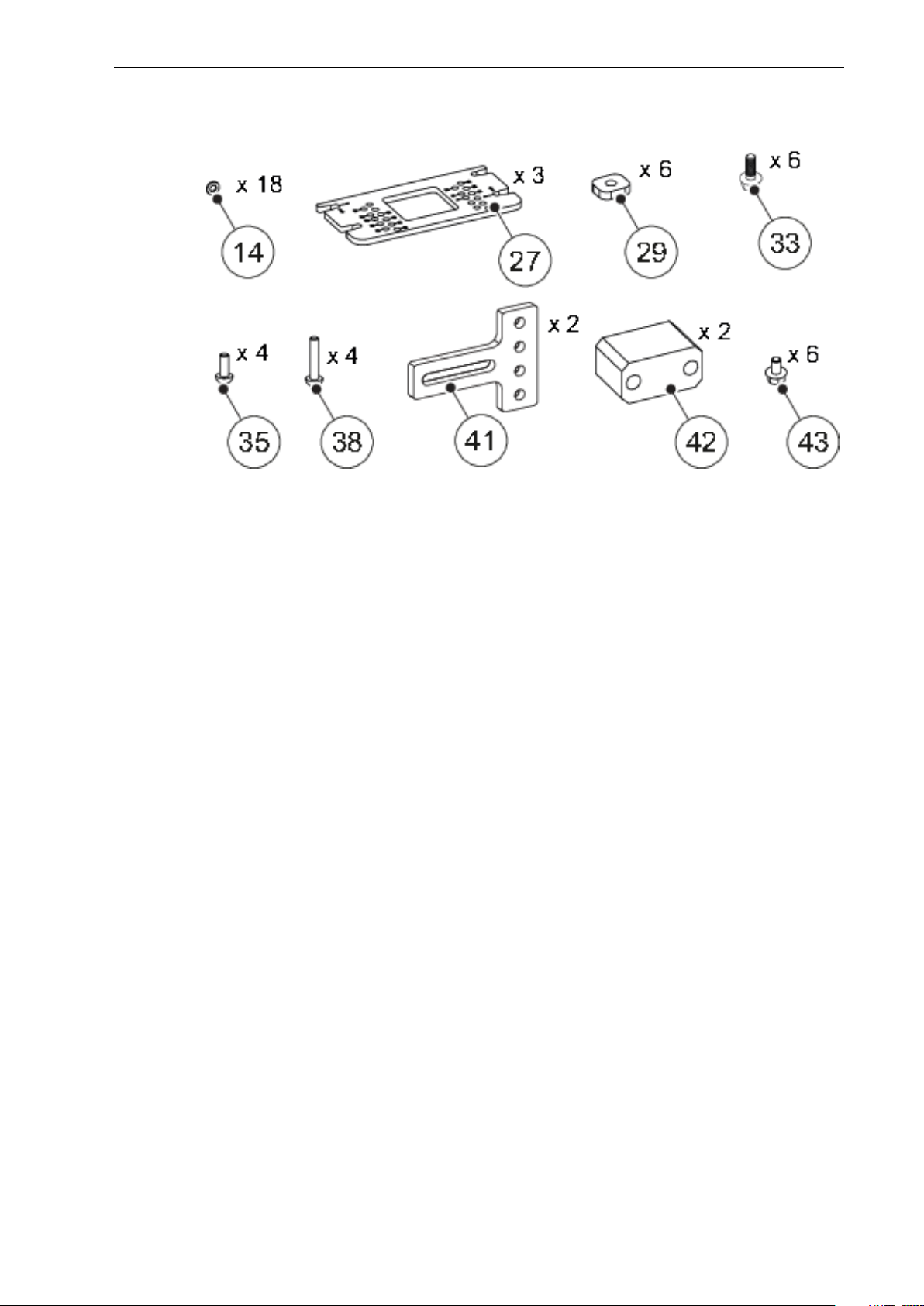
Check B3 kit
2 Mechanical installation
Washer: ISO 7089 (BRB) 6.4x12x1.5 FZB14
Mounting plate27
Square nut: M629
Screw: DIN 6921 (M6SF) M6x14 FZB 8.833
Screw: ISO 14583 (MRT-TT) M6x16 FZB 8.835
Screw: ISO 14583 (MRT-TT) M6x35 FZB 8.838
Bracket 341
Spacer block42
Screw: DIN 6921 (M6SF) M6x10 FZB 8.843
9Issue 2019-07-131018482-EMen-2.0
Page 10
2 Mechanical installation
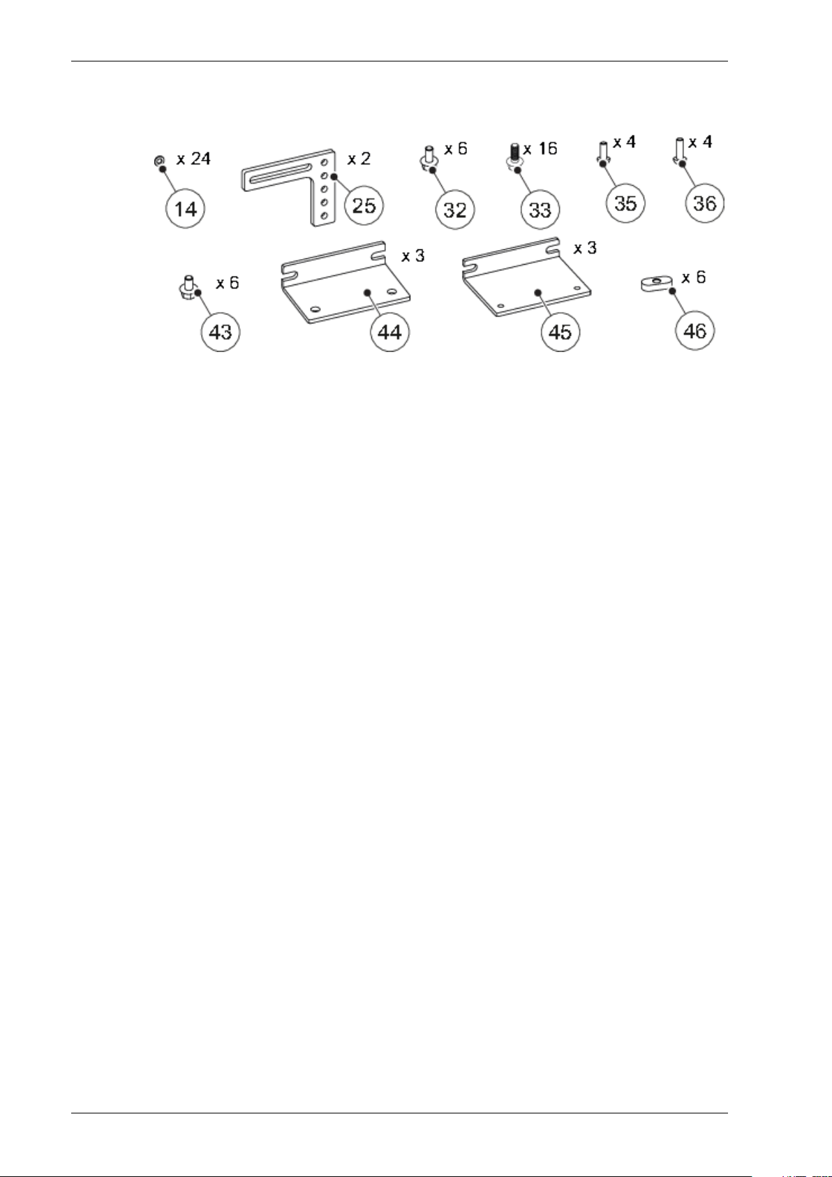
Check B4 kit
Washer: ISO 7089 (BRB) 6.4x12x1.5 FZB14
Bracket 125
Screw: DIN 6921 (M6SF) M6x12 FZB 8.832
Screw: DIN 6921 (M6SF) M6x14 FZB 8.833
Screw: ISO 14583 (MRT-TT) M6x16 FZB 8.835
Screw: ISO 14583 (MRT-TT) M6x20 FZB 8.836
Screw: DIN 6921 (M6SF) M6x10 FZB 8.843
Bracket 444
Bracket 545
Nut: M646
1018482-EMen-2.0Issue 2019-07-1310
Page 11
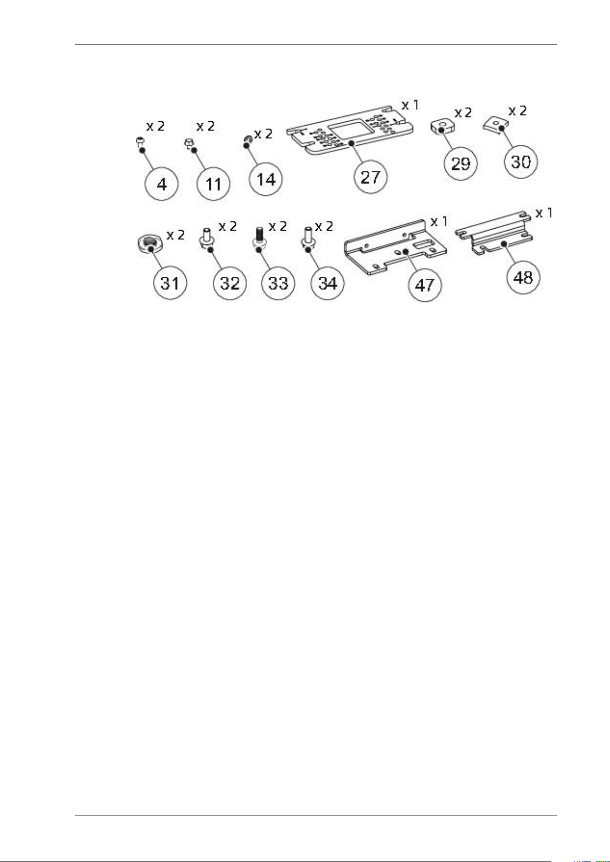
Check belt lock fixing bracket kit 1
2 Mechanical installation
Screw: ISO 14583 (MRT-TT) M6x10 FZB 8.84
Screw: DIN 6921 (M6SF) M6x8 FZB 8.811
Washer: ISO 7089 (BRB) 6.4x12x1.5 FZB14
Mounting plate27
Square nut: M629
Nut30
Nut: ISO 4035 (ML6M) M6 FZB31
Screw: DIN 6921 (M6SF) M6x12 FZB 8.832
Screw: DIN 6921 (M6SF) M6x14 FZB 8.833
Screw: DIN 6921 (M6SF) M6x16 FZB 8.834
Fixing bracket47
Mounting bracket48
11Issue 2019-07-131018482-EMen-2.0
Page 12
2 Mechanical installation
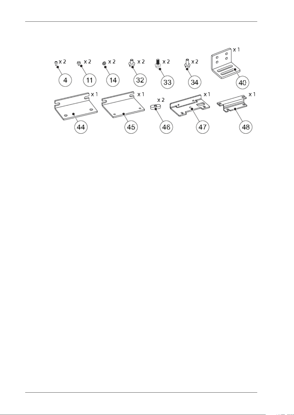
Check belt lock fixing bracket kit 2
Screw: ISO 14583 (MRT-TT) M6x10 FZB 8.84
Screw: DIN 6921 (M6SF) M6x8 FZB 8.811
Washer: ISO 7089 (BRB) 6.4x12x1.5 FZB14
Screw: DIN 6921 (M6SF) M6x14 FZB 8.833
Screw: DIN 6921 (M6SF) M6x16 FZB 8.834
Bracket 240
Screw: DIN 6921 (M6SF) M6x10 FZB 8.843
Bracket 444
Bracket 545
Nut: M646
Fixing bracket47
Mounting bracket48
1018482-EMen-2.0Issue 2019-07-1312
Page 13
2 Mechanical installation
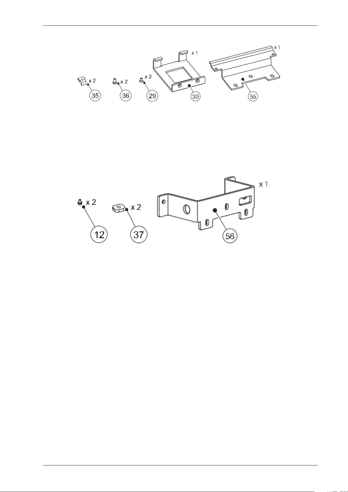
Nut: M535
Screw: ISO 14583 (MRT) M5x10 FZB 8.836
Screw: ISO 7046 (MFTS) M3x5 FZB 8.829
Belt guide30
Fixing bracket (belt lock) TORMAX iMotion
55
2202
Screw: DIN 6921 (M6SF) M6x10 FZB 8.812
Square nut: M637
Fixing bracket (belt lock) GEZE Slimdrive56
13Issue 2019-07-131018482-EMen-2.0
Page 14
2 Mechanical installation
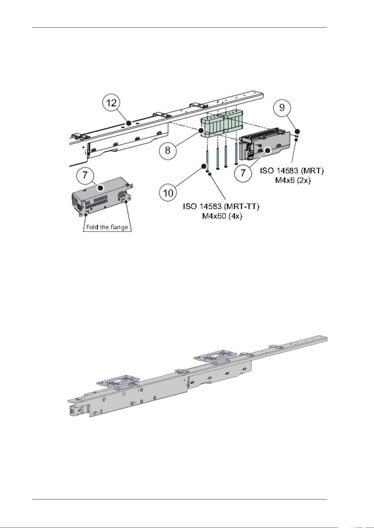
2.1.2 I/O board and the battery installation (option)
Note! I/O board must be selected when bi-stable.
Fix the I/O board (7) and the battery (8) to the backbone assembly (12) with the screws (9) and
(10).
2.1.3 Fix the brackets to the backbone assembly
Note! The brackets in the picture is only an example, please choose the suitable brackets for the
specified operator that shall be upgraded.
I/O board7
Battery8
Screw: ISO 14583 (MRT) M4x69
Screw: ISO 14583 (MRT-TT) M4x6010
Backbone assembly12
1018482-EMen-2.0Issue 2019-07-1314
Page 15
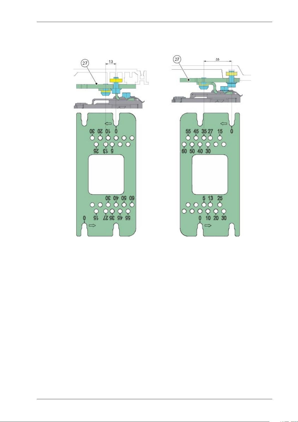
2 Mechanical installation
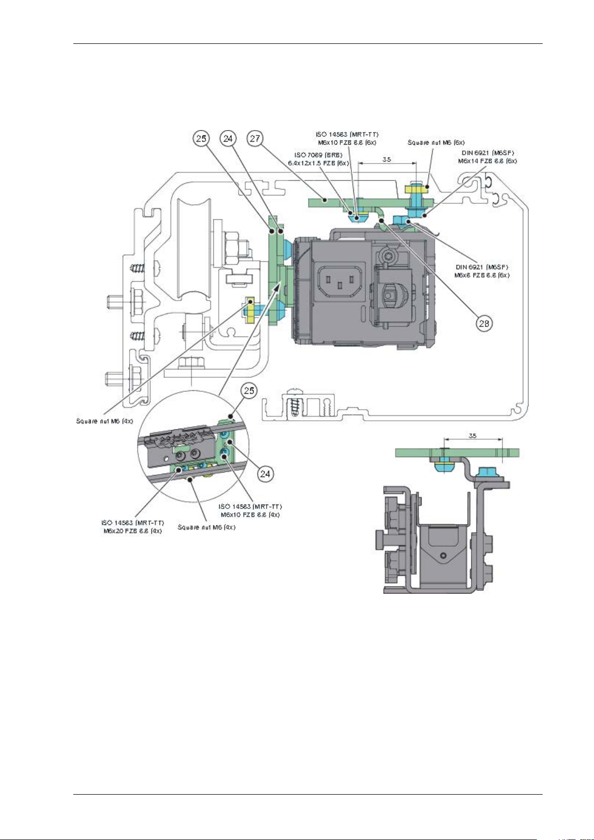
a How to install the mounting plate. Please refer to the dimension on the surface of plate (27)
firstly.
Mounting plate27
15Issue 2019-07-131018482-EMen-2.0
Page 16
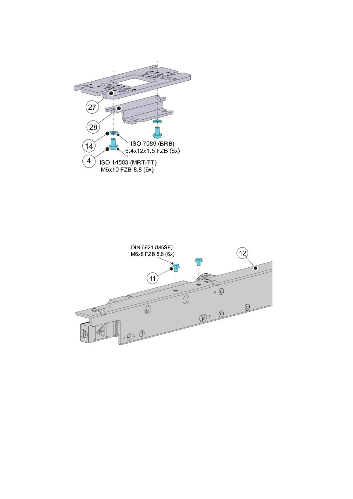
2 Mechanical installation
b Assemble themountingplate (27) and mounting bracket (28) with the washers (14) and screws
(4).
Screw: ISO 14583 (MRT-TT) M6x10 FZB 8.84
Washer: ISO 7089 (BRB) 6.4x12x1.5 FZB14
Mounting plate27
Mounting bracket28
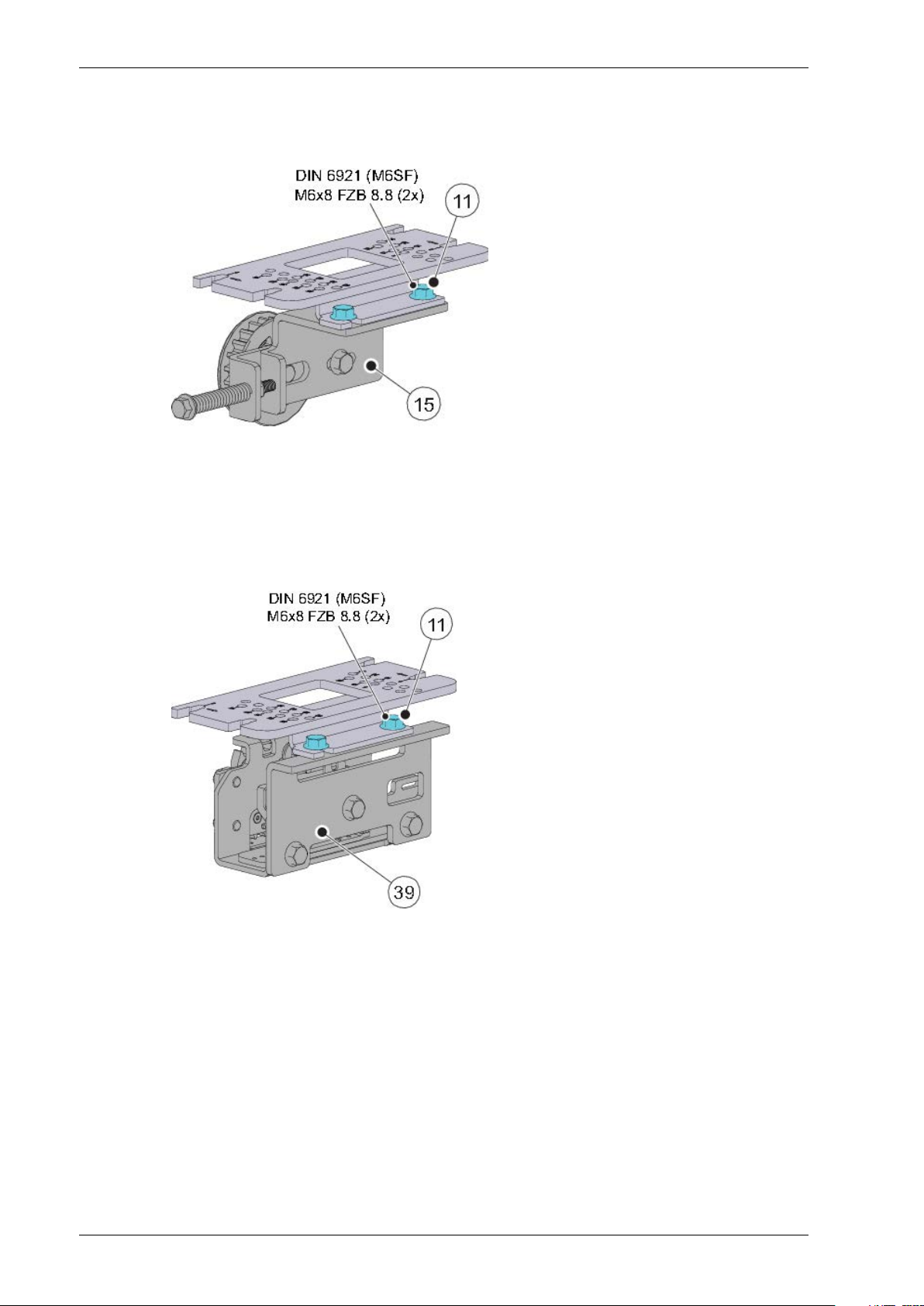
c Fix two screws (11) to the backbone assembly (12), don't tighten the screws (11).
Screw: DIN 6921 (M6SF) M6x8 FZB 8.811
Backbone assembly12
1018482-EMen-2.0Issue 2019-07-1316
Page 17
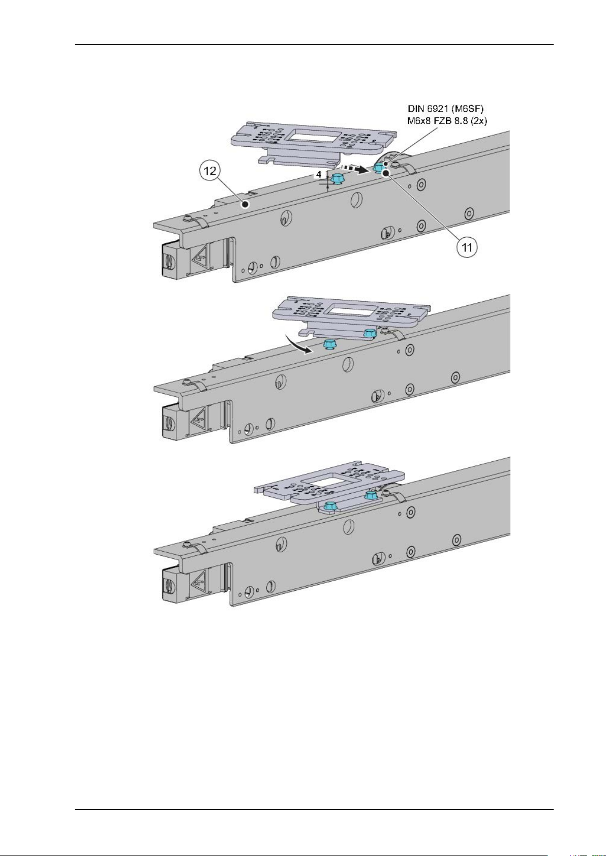
2 Mechanical installation
d Fix the brackets to the backbone assembly (12), then tighten the screws (11) with a torque of
8 - 10 Nm.
Screw: DIN 6921 (M6SF) M6x8 FZB 8.811
Backbone assembly12
17Issue 2019-07-131018482-EMen-2.0
Page 18
2 Mechanical installation
2.1.4 Fix the brackets to the tension wheel
Fix the brackets to the tension wheel assembly (15) in the same way as 2.1.3 .
Screw: DIN 6921 (M6SF) M6x8 FZB 8.811
Tension wheel assembly15
2.1.5 Fix the brackets to the belt lock (option)
Fix the brackets to the belt lock (39) in the same way as 2.1.3.
Screw: DIN 6921 (M6SF) M6x8 FZB 8.811
Belt lock39
1018482-EMen-2.0Issue 2019-07-1318
Page 19
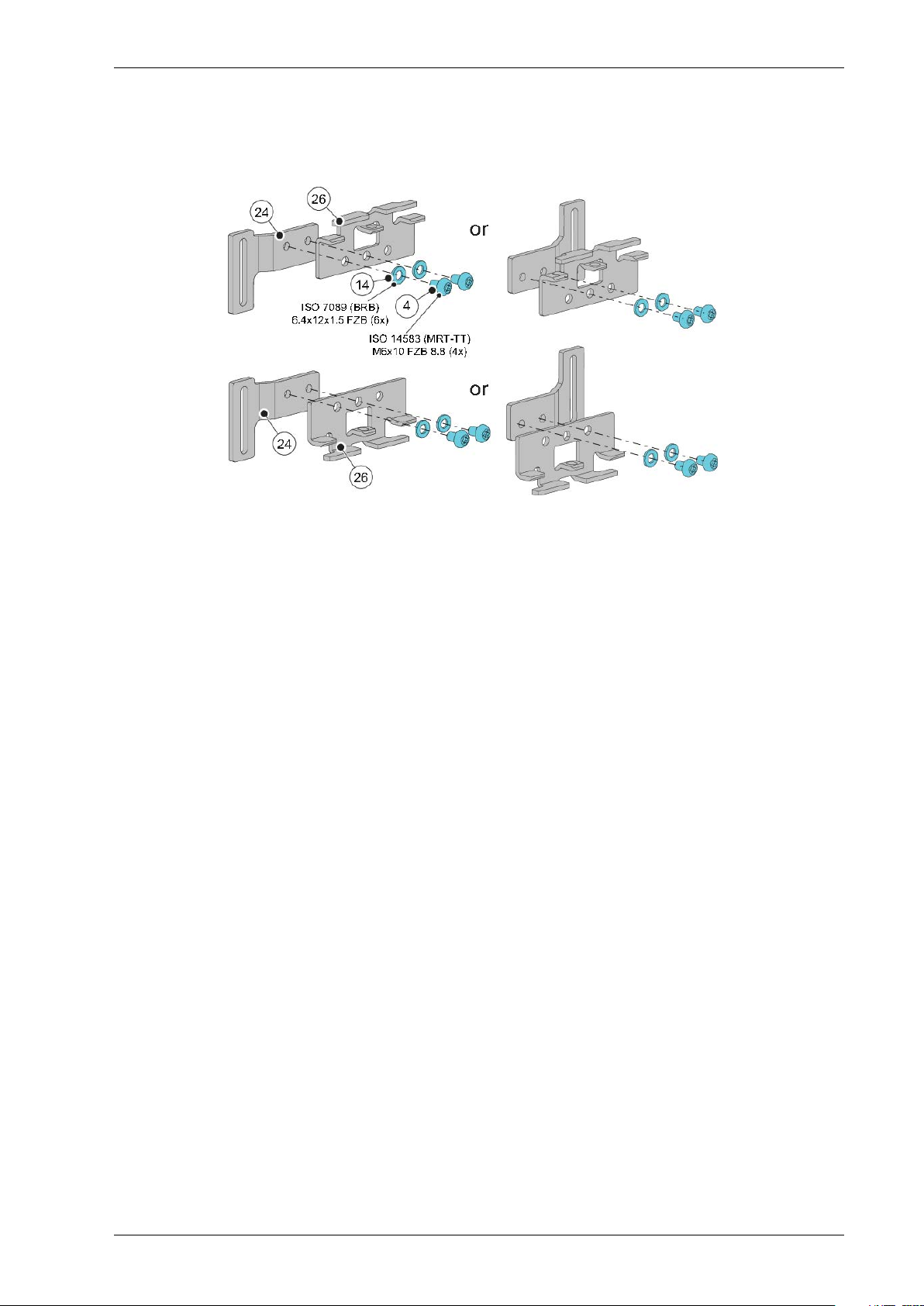
2.1.6 Fix the transmission bracket to the connecting bracket
a Fix the transmission bracket (26) to the connecting bracket (24) with the screws (4) and
washers (14).
2 Mechanical installation
2.1.7 Attachment of slack reducer
Please refer to PSL150 Installation and Service Manual (1016248).
Screw: ISO 14583 (MRT-TT) M6x10 FZB 8.84
Washer: ISO 7089 (BRB) 6.4x12x1.5 FZB14
Connecting bracket24
Transmission bracket26
19Issue 2019-07-131018482-EMen-2.0
Page 20
2 Mechanical installation
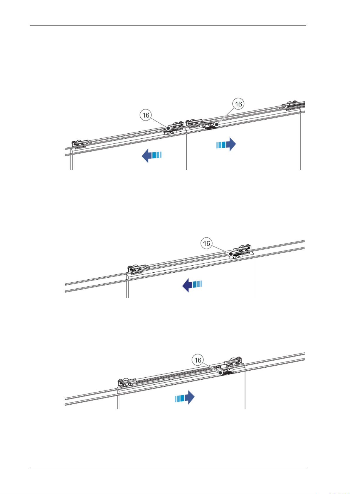
2.1.8 General rules of the installation
Position of the belt connecting to the transmission brackets.
Bi-parting opening
The transmission bracket (16) on the left door leaf shall be connected to the upper belt.
The transmission bracket (16) on the right door leaf shall be connected to the lower belt.
Transmission bracket16
Single left opening
The transmission bracket (16) shall be connected to the upper belt.
Transmission bracket16
Single right opening
The transmission bracket (16) shall be connected to the lower belt.
Transmission bracket16
1018482-EMen-2.0Issue 2019-07-1320
Page 21

2.1.9 List of the adapted door types
2 Mechanical installation
Bracket kitPageOperator Brand&TypeItem
Belt lock fixing
bracket kit
B123ATS CLIXMASTER1
B124ATS TSF 21002
B125Baumgartner Al-Profil3
B226Baumgartner steel4
B127DORMA ES 505
B128DORMA ES 55/606
B129DORMA ES 707
B130DORMA ES 90/1008
B331DORMA ES 2009
B132ELDEBE GSX10
B133EMD11
B134EMC12
B135Faiveley 613
1019396
B136Faiveley 1214
B137Faiveley 1715
B338GEZE ECdrive16
B139GEZE TSA 34017
B140GEZE TSA 350 N/350 W18
B141GEZE TSA 36019
B142GEZE TSA 45020
B143Gilgen SLK/SLG21
B144Gilgen SLM/SLP22
B145HORTON Series 200123
B146Manusa PA 8024
B147Manusa STK25
1019399B448Manusa Visio26
B249Portalp 2000B27
B150Porte Automatiche GTS-L/-P28
B151Porte Automatiche GTV29
B252Record STA730
1019396
B253Record STA831
B154Record STA9/STA1032
B155Record STA1133
B156Record STA12/STA14 Steel34
1019399B457Record STA12/STA14 AL35
B158Record STA1336
B159Record STA1537
1019396
B160Record STA16/1738
21Issue 2019-07-131018482-EMen-2.0
Page 22

2 Mechanical installation
Bracket kitPageOperator Brand&TypeItem
Belt lock fixing
bracket kit
B461Record STA1939
B462Record STA2040
1019399
B463Record STA2141
B164Tormax TMP42
B165Tormax TX/TM/TMX43
1019396
B166Tormax TEP/TXP44
B167Waldoor EC45
1019399B268Waldoor UC46
1019396B169Waldoor UWS 80047
1019399B470Waldoor UWS 240048
1019396B171Ditec VALOR (escape route)49
B272Ditec Bis O50
1019396
B273Ditec Bis V51
1018482-EMen-2.0Issue 2019-07-1322
Page 23
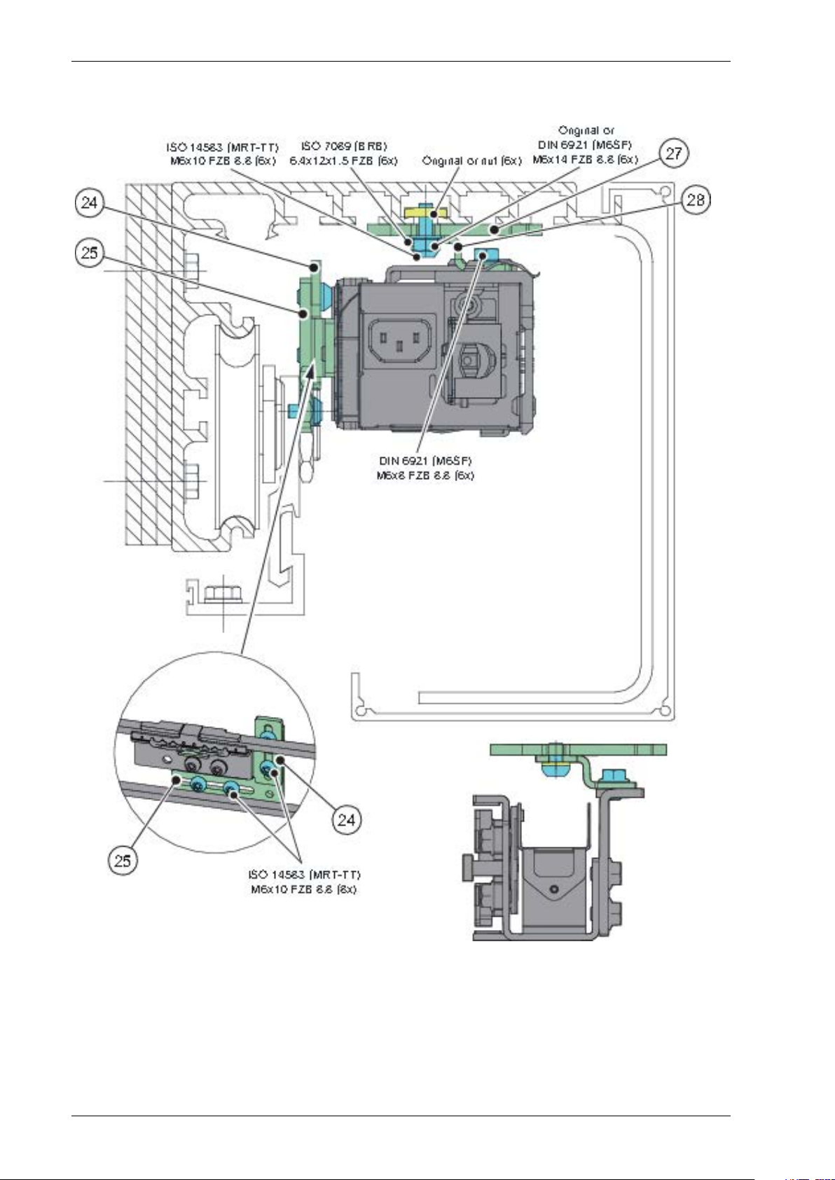
2.1.10 Adapted door types
Note! Original nuts and bolts can be reused.
ATS CLIXMASTER
2 Mechanical installation
Connecting bracket24
Bracket 125
Mounting plate27
Mounting bracket28
23Issue 2019-07-131018482-EMen-2.0
Page 24
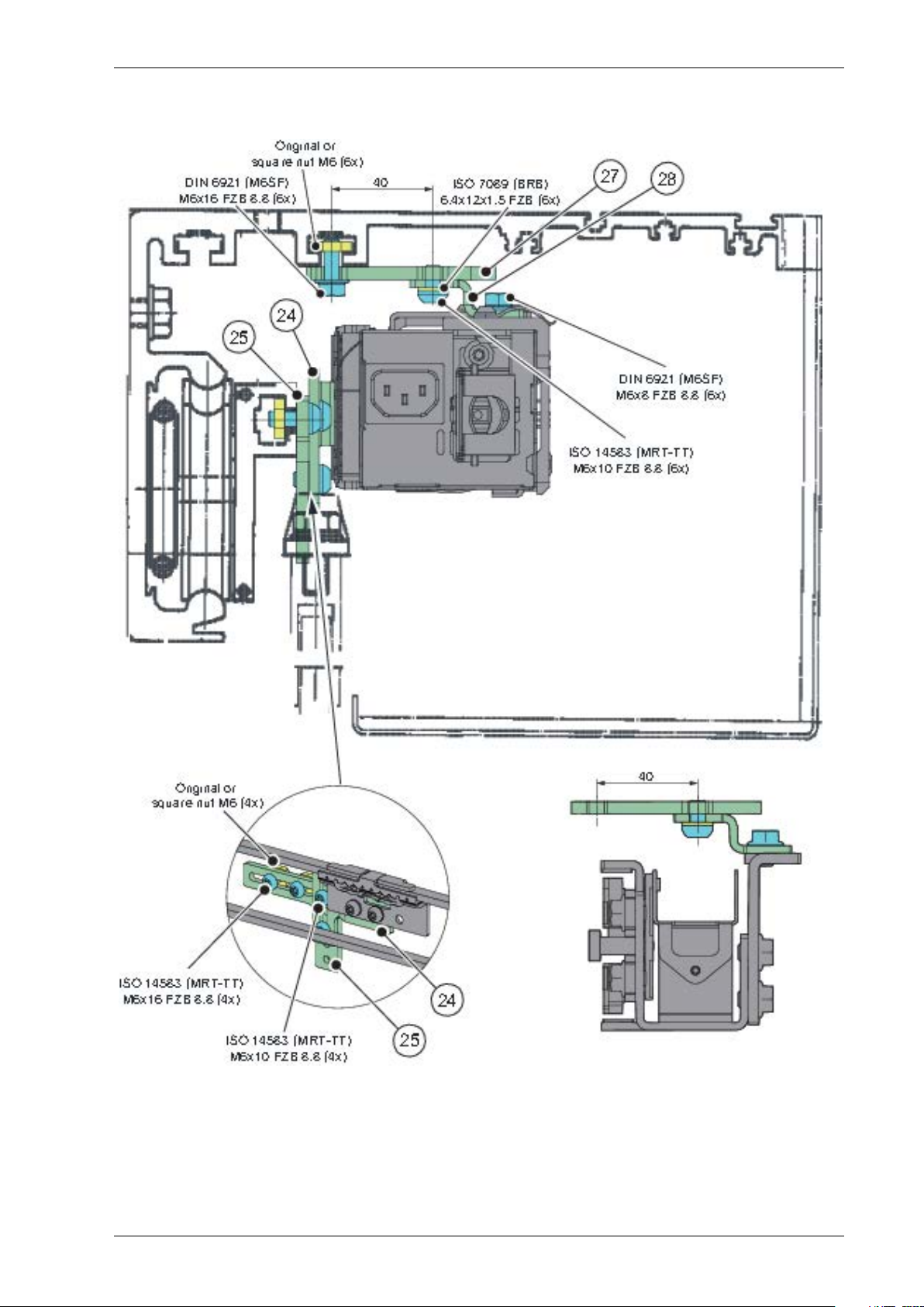
2 Mechanical installation
ATS TSF 2100
Connecting bracket24
Bracket 125
Mounting plate27
Mounting bracket28
1018482-EMen-2.0Issue 2019-07-1324
Page 25
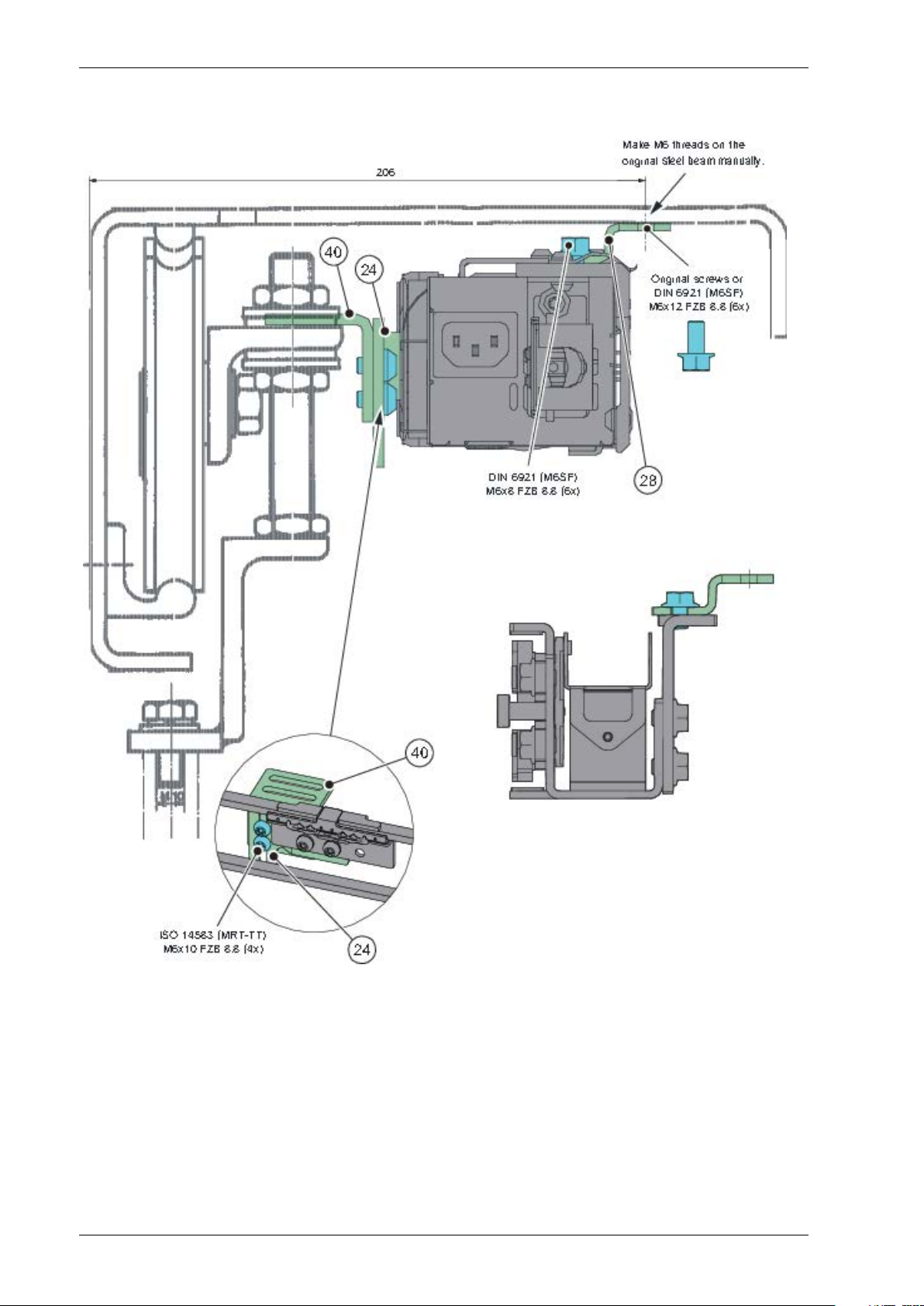
Baumgartner Al-Profil
2 Mechanical installation
Connecting bracket24
Bracket 125
Mounting plate27
Mounting bracket28
25Issue 2019-07-131018482-EMen-2.0
Page 26
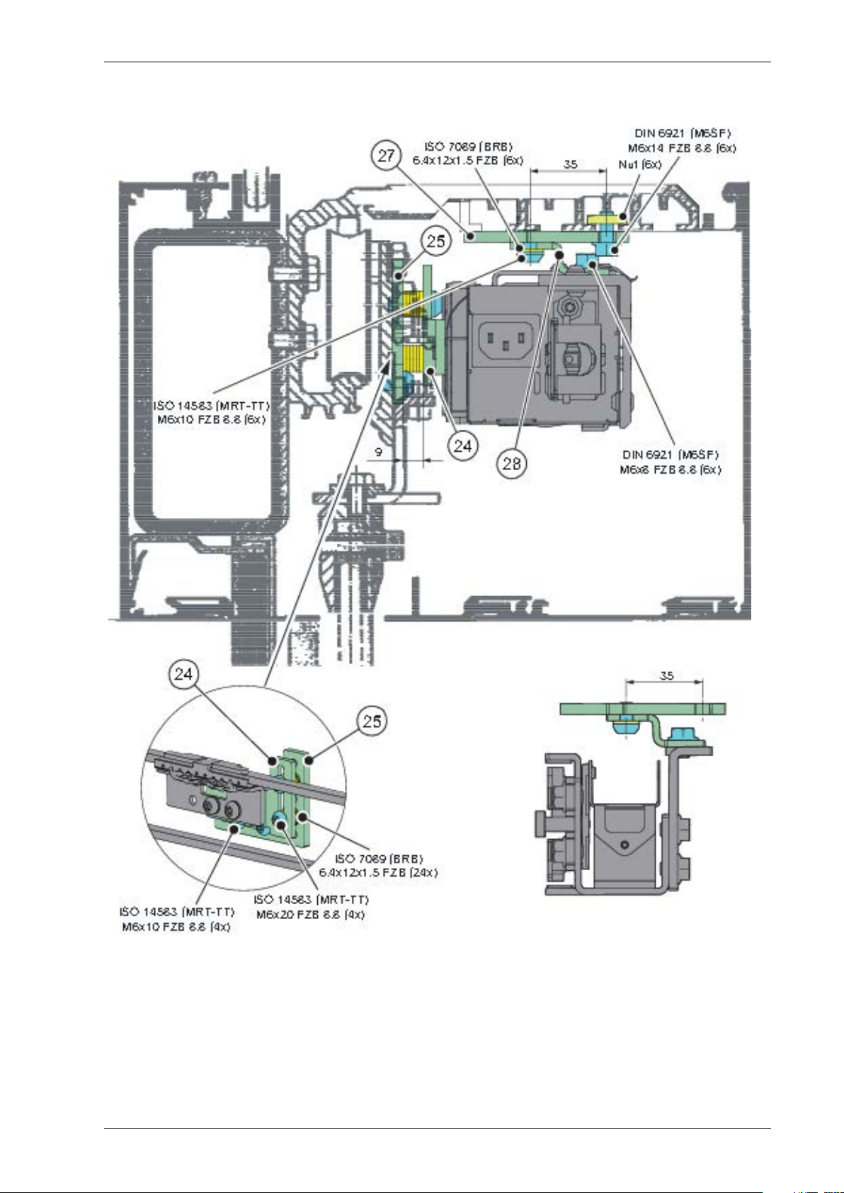
2 Mechanical installation
Baumgartner steel
Connecting bracket24
Mounting bracket28
Bracket 240
1018482-EMen-2.0Issue 2019-07-1326
Page 27
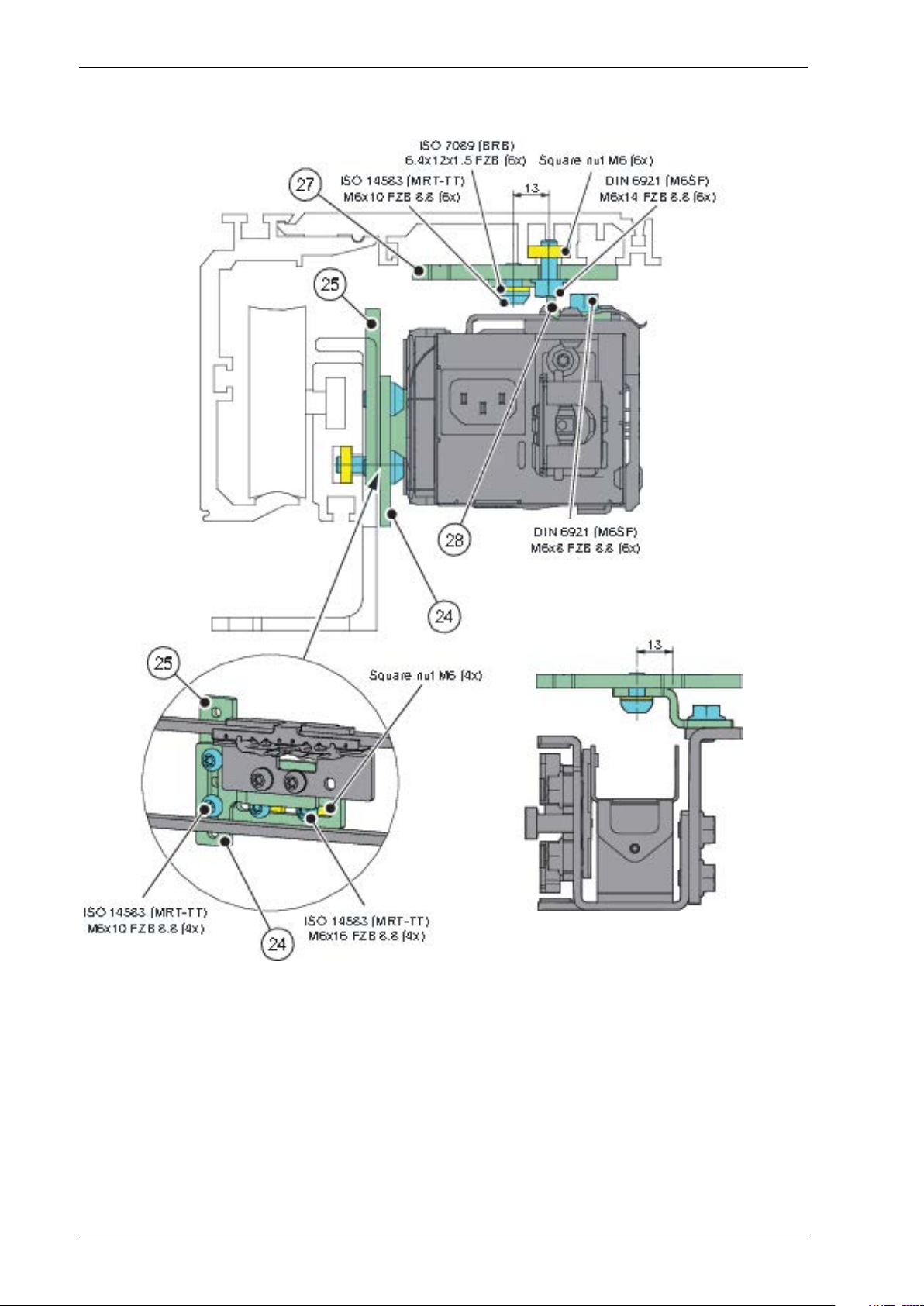
DORMA ES 50
2 Mechanical installation
Connecting bracket24
Bracket 125
Mounting plate27
Mounting bracket28
27Issue 2019-07-131018482-EMen-2.0
Page 28
2 Mechanical installation
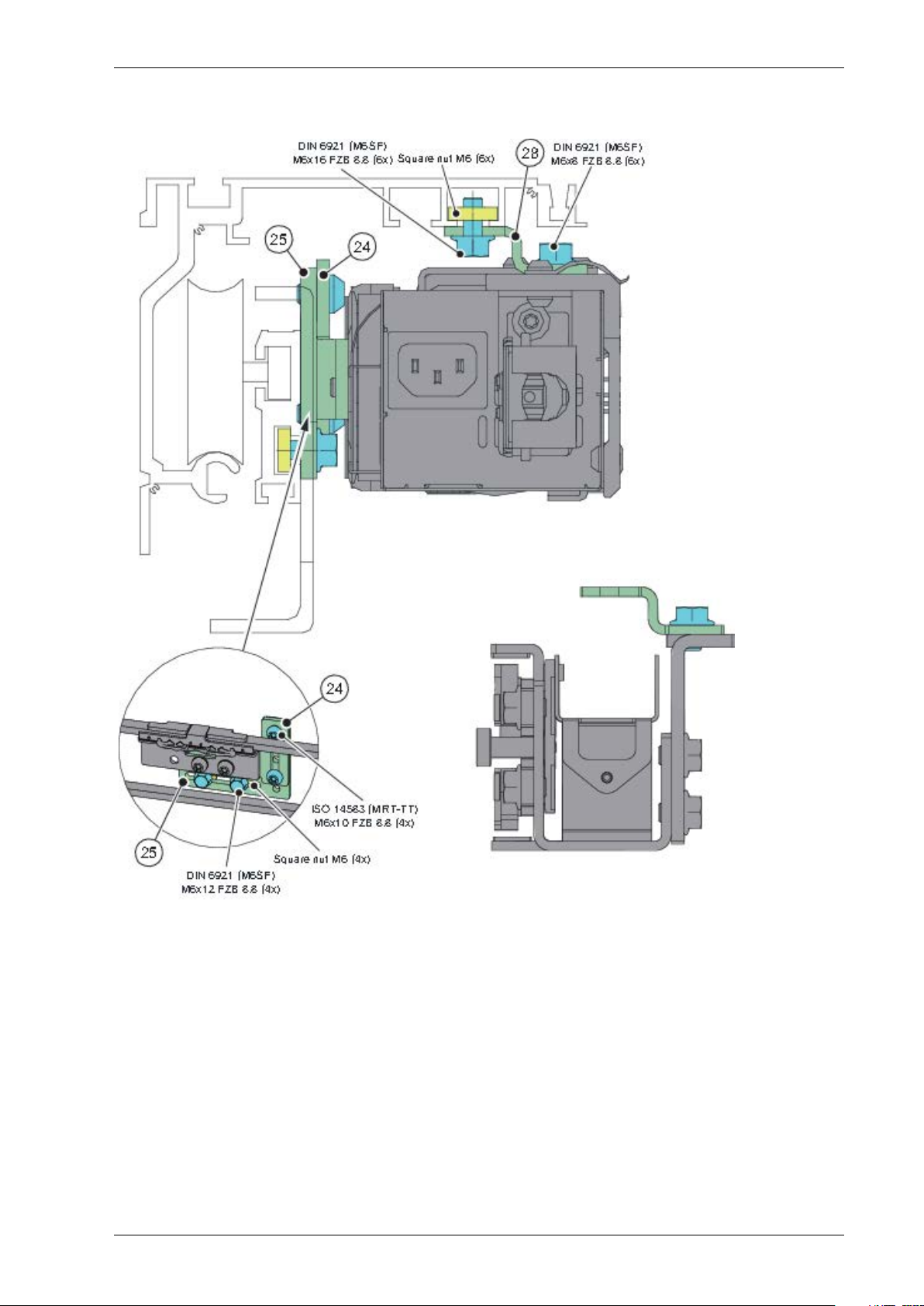
DORMA ES 55/60
Connecting bracket24
Bracket 125
Mounting plate27
Mounting bracket28
1018482-EMen-2.0Issue 2019-07-1328
Page 29
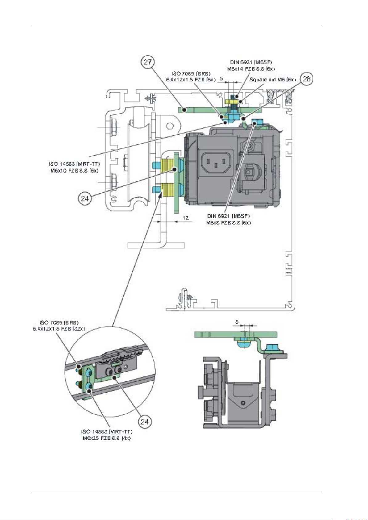
DORMA ES 70
2 Mechanical installation
Connecting bracket24
Mounting plate27
Mounting bracket28
29Issue 2019-07-131018482-EMen-2.0
Page 30
2 Mechanical installation
DORMA ES 90/100
Connecting bracket24
Mounting plate27
Mounting bracket28
1018482-EMen-2.0Issue 2019-07-1330
Page 31

DORMA ES 200
2 Mechanical installation
Connecting bracket24
Mounting plate27
Mounting bracket28
Bracket 341
31Issue 2019-07-131018482-EMen-2.0
Page 32

2 Mechanical installation
ELDEBE GSX
Connecting bracket24
Mounting plate27
Mounting bracket28
1018482-EMen-2.0Issue 2019-07-1332
Page 33

EMD
2 Mechanical installation
Connecting bracket24
Mounting plate27
Mounting bracket28
33Issue 2019-07-131018482-EMen-2.0
Page 34

2 Mechanical installation
EMC
Connecting bracket24
Mounting plate27
Mounting bracket28
1018482-EMen-2.0Issue 2019-07-1334
Page 35

Faiveley 6
2 Mechanical installation
Connecting bracket24
Bracket 125
Mounting plate27
Mounting bracket28
35Issue 2019-07-131018482-EMen-2.0
Page 36

2 Mechanical installation
Faiveley 12
Connecting bracket24
Bracket 125
Mounting plate27
Mounting bracket28
1018482-EMen-2.0Issue 2019-07-1336
Page 37

Faiveley 17
2 Mechanical installation
Connecting bracket24
Bracket 125
Mounting plate27
Mounting bracket28
37Issue 2019-07-131018482-EMen-2.0
Page 38

2 Mechanical installation
GEZE ECdrive
Connecting bracket24
Bracket 125
Mounting bracket28
1018482-EMen-2.0Issue 2019-07-1338
Page 39

GEZE TSA 340
2 Mechanical installation
Connecting bracket24
Mounting bracket28
39Issue 2019-07-131018482-EMen-2.0
Page 40

2 Mechanical installation
GEZE TSA 350 N/350 W
Connecting bracket24
Bracket 125
Mounting bracket28
1018482-EMen-2.0Issue 2019-07-1340
Page 41

GEZE TSA 360
2 Mechanical installation
Connecting bracket24
Bracket 125
Mounting bracket28
41Issue 2019-07-131018482-EMen-2.0
Page 42

2 Mechanical installation
GEZE TSA 450
Connecting bracket24
Bracket 125
Mounting bracket28
1018482-EMen-2.0Issue 2019-07-1342
Page 43

Gilgen SLK/SLG
2 Mechanical installation
Connecting bracket24
Bracket 125
Mounting bracket28
43Issue 2019-07-131018482-EMen-2.0
Page 44

2 Mechanical installation
Gilgen SLM/SLP
Connecting bracket24
Bracket 125
Mounting bracket28
1018482-EMen-2.0Issue 2019-07-1344
Page 45

HORTON Series 2001
2 Mechanical installation
Connecting bracket24
Bracket 125
Mounting plate27
Mounting bracket28
45Issue 2019-07-131018482-EMen-2.0
Page 46

2 Mechanical installation
Manusa PA 80
Connecting bracket24
Bracket 125
Mounting plate27
Mounting bracket28
1018482-EMen-2.0Issue 2019-07-1346
Page 47

Manusa STK
2 Mechanical installation
Connecting bracket24
Bracket 125
Mounting plate27
Mounting bracket28
47Issue 2019-07-131018482-EMen-2.0
Page 48

2 Mechanical installation
Manusa Visio
Connecting bracket24
Bracket 444
1018482-EMen-2.0Issue 2019-07-1348
Page 49

Portalp 2000B
2 Mechanical installation
Bracket11
Backbone assembly12
Screw: ISO 4014 (M6S) M6x813
49Issue 2019-07-131018482-EMen-2.0
Page 50

2 Mechanical installation
Porte Automatiche GTS-L/-P
Connecting bracket24
Bracket 125
Mounting plate27
Mounting bracket28
1018482-EMen-2.0Issue 2019-07-1350
Page 51

Porte Automatiche GTV
2 Mechanical installation
Connecting bracket24
Mounting plate27
Mounting bracket28
51Issue 2019-07-131018482-EMen-2.0
Page 52

2 Mechanical installation
Record STA7
Connecting bracket24
Mounting bracket28
Bracket 240
1018482-EMen-2.0Issue 2019-07-1352
Page 53

Record STA8
2 Mechanical installation
Connecting bracket24
Bracket 125
Mounting bracket28
Bracket 240
53Issue 2019-07-131018482-EMen-2.0
Page 54

2 Mechanical installation
Record STA9/STA10
Connecting bracket24
Bracket 125
Mounting bracket28
1018482-EMen-2.0Issue 2019-07-1354
Page 55

Record STA11
2 Mechanical installation
Connecting bracket24
Bracket 125
Mounting plate27
Mounting bracket28
55Issue 2019-07-131018482-EMen-2.0
Page 56

2 Mechanical installation
Record STA12/STA14 Steel
Connecting bracket24
Bracket 125
Mounting bracket28
1018482-EMen-2.0Issue 2019-07-1356
Page 57

Record STA12/STA14 AL
2 Mechanical installation
Connecting bracket24
Bracket 125
Bracket 444
57Issue 2019-07-131018482-EMen-2.0
Page 58

2 Mechanical installation
Record STA13
Connecting bracket24
Bracket 125
Mounting bracket28
1018482-EMen-2.0Issue 2019-07-1358
Page 59

Record STA15
2 Mechanical installation
Connecting bracket24
Bracket 125
Mounting bracket28
59Issue 2019-07-131018482-EMen-2.0
Page 60

2 Mechanical installation
Record STA16/17
Note! * Cut the original component holder beam to smaller pieces.
Bi-parting
2/3 of the original beam for backbone assembly.
1/6 of the original beam for tension wheel.
1/6 of the original beam for belt lock.
Left opening
2/3 of the original beam for backbone assembly.
1/3 of the original beam for tension wheel and belt lock.
Right opening
2/3 of the original beam for backbone assembly and belt lock.
1/3 of the original beam for tension wheel.
Connecting bracket24
Bracket 125
Mounting plate27
Mounting bracket28
1018482-EMen-2.0Issue 2019-07-1360
Page 61

Record STA19
2 Mechanical installation
Connecting bracket24
Mounting bracket28
61Issue 2019-07-131018482-EMen-2.0
Page 62

2 Mechanical installation
Record STA20
Connecting bracket24
Bracket 444
1018482-EMen-2.0Issue 2019-07-1362
Page 63

Record STA21
2 Mechanical installation
Connecting bracket24
Mounting bracket28
63Issue 2019-07-131018482-EMen-2.0
Page 64

2 Mechanical installation
Tormax TMP
Connecting bracket24
Bracket 125
Mounting plate27
Mounting bracket28
1018482-EMen-2.0Issue 2019-07-1364
Page 65

Tormax TX/TM/TMX
2 Mechanical installation
Connecting bracket24
Bracket 125
Mounting bracket28
65Issue 2019-07-131018482-EMen-2.0
Page 66

2 Mechanical installation
Tormax TEP/TXP
Bracket11
Backbone assembly12
Screw: ISO 4014 (M6S) M6x813
1018482-EMen-2.0Issue 2019-07-1366
Page 67

Waldoor EC
2 Mechanical installation
Connecting bracket24
Mounting bracket28
67Issue 2019-07-131018482-EMen-2.0
Page 68

2 Mechanical installation
Waldoor UC
Bracket11
Backbone assembly12
Screw: ISO 4014 (M6S) M6x813
1018482-EMen-2.0Issue 2019-07-1368
Page 69

Waldoor UWS 800
2 Mechanical installation
Connecting bracket24
Bracket 125
Mounting plate27
Mounting bracket28
69Issue 2019-07-131018482-EMen-2.0
Page 70

2 Mechanical installation
Waldoor UWS 2400
Connecting bracket24
Bracket 125
Mounting bracket28
Bracket 545
1018482-EMen-2.0Issue 2019-07-1370
Page 71

Ditec VALOR (escape route)
2 Mechanical installation
Connecting bracket24
Mounting bracket28
Bracket 545
71Issue 2019-07-131018482-EMen-2.0
Page 72

2 Mechanical installation
Ditec Bis O
Connecting bracket24
Mounting plate27
Mounting bracket28
Bracket 240
1018482-EMen-2.0Issue 2019-07-1372
Page 73

Ditec Bis V
2 Mechanical installation
Connecting bracket24
Mounting plate27
Mounting bracket28
Bracket 240
73Issue 2019-07-131018482-EMen-2.0
Page 74

2 Mechanical installation
2.2 Entrematic PSL Retrofit Kit for TORMAX iMotion 2202
2.2.1 Check the components
Check the components in the package as following.
Drive unit kit13
Main control assembly14
Tension wheel assembly15
Tooth belt18
Belt clamp20
Nut: DIN 985 M6 (M6M)25
Screw: ISO 14581 (MFT) M6x1226
Transmission bracket27
Universal transmission bracket28
Nut: M535
Screw: ISO 14583 (MRT) M5x1036
Slack reducer (Not needed, if belt lock
37
equipped)
1018482-EMen-2.0Issue 2019-07-1374
Page 75

2.2.2 Preparing
a Dismount the original drive system, following components should be retained: door carriers
(1), beam (2), cover set (3), door stops (4), cable holders (5), nuts (11) and screws (12).
Note! If there are not enough nuts (11) and screws (12), use the nuts (35) and the screws (36)
to replace.
2 Mechanical installation
Door carrier1
Beam2
Cover set3
Door stop4
Cable holder5
Nut: M511
Screw: M5x1012
Nut: M535
Screw: ISO 14583 (MRT) M5x1036
75Issue 2019-07-131018482-EMen-2.0
Page 76

2 Mechanical installation
2.2.3 I/O board and the battery installation (option)
Note! I/O board must be selected when bi-stable.
a Fix the I/O board (7) and the battery (8) to the main control assembly (14) with the screws (9)
and (10).
I/O board7
Battery8
Screw: ISO 14583 (MRT) M4x69
Screw: ISO 14583 (MRT-TT) M4x6010
Main control assembly14
1018482-EMen-2.0Issue 2019-07-1376
Page 77

2.2.4 Fix the nuts and screws on the drive unit kit and the main control assembly
a Take off the drive unit from the Backbone assembly (40), then fix it onto drive unit plate (57)
with the original screws and washeres.
2 Mechanical installation
Backbone assembly40
Drive unit plate57
77Issue 2019-07-131018482-EMen-2.0
Page 78

2 Mechanical installation
b Take off the PSU from the Backbone assembly (40), then fix it onto drive unit plate (57) with
the original screws and other components.
Backbone assembly40
Drive unit plate57
1018482-EMen-2.0Issue 2019-07-1378
Page 79

2 Mechanical installation
c Take off the MCU from the Backbone assembly (40), then fix it onto electronic mounting plate
(58) with the original screws and washeres.
Backbone assembly40
Electronic mounting plate58
79Issue 2019-07-131018482-EMen-2.0
Page 80

2 Mechanical installation
d Fix the nuts (11) to the drive unit kit (13) and main control assembly (14) with screws (12), but
do not tighten the screws (12).
Nut: M511
Screw: M5x1012
Drive unit kit (HD or DD)13
Main control assembly14
1018482-EMen-2.0Issue 2019-07-1380
Page 81

2.2.5 Fix the drive unit kit and the main control assembly
a Lift the drive unit kit (13) and main control assembly (14) to the beam (2), Then tighten the
screws (12) with a torque of 6 Nm.
2 Mechanical installation
Beam2
Nut: M511
Screw: M5x1012
Drive unit kit (HD or DD)13
Main control assembly14
81Issue 2019-07-131018482-EMen-2.0
Page 82

2 Mechanical installation
2.2.6 Fix the tension wheel assembly
a Fix the nuts (11) to the tension wheel assembly (15) with screws (12), but do not tighten the
screws (12).
Lift the tension wheel assembly (15) to the beam (2), do not tighten the screws (12) fully, so it
shall be able to slide along the beam (2).
b The position of the tension wheel assembly (15) should be as close as possible to the drive unit,
but make sure that the tension wheel assembly (15) will not interfere with the door carrier
when the door is fully opened.
Beam2
Nut: M511
Screw: M5x1012
Tension wheel assembly15
1018482-EMen-2.0Issue 2019-07-1382
Page 83

2.2.7 Fix the transmission brackets
a Unscrew the existing screws (24), fix the transmission brackets (27) and the universal transmis-
sion brackets (28) to the door carriers (1) with the screws (24) and (26).
Note! The door leaves should be holded firmly when unscrew the the existing screws (24) on
the door carriers (1).
2 Mechanical installation
Door carrier1
Existing screw: M6x1424
Nut: DIN 985 M6 (M6M)25
Screw: ISO 14581 (MFT) M6x1226
Transmission bracket27
Universal transmission bracket28
83Issue 2019-07-131018482-EMen-2.0
Page 84

2 Mechanical installation
2.2.8 Placement of the transmission brackets
Bi-parting opening
The transmission bracket (16) on the left door leaf shall be connected to the inner belt.
The transmission bracket (16) on the right door leaf shall be connected to the outer belt.
Transmission bracket16
Single left opening
The transmission bracket (16) shall be connected to the inner belt.
Transmission bracket16
Single right opening
The transmission bracket (16) shall be connected to the outer belt.
Transmission bracket16
1018482-EMen-2.0Issue 2019-07-1384
Page 85

2.2.9 Attachment of the tooth belt
a Cut the tooth belt (18) to the right length if needed. Route the tooth belt (18) around the drive
unit pulley (19) and around the tension wheel assembly (15).
b For bi-parting doors the belt ends are joined with the belt clamp (20) in the outer part of the
tooth belt (18).
c Click the belt clamp (20) into position.
Note! Do not adjust parameter P12!
2 Mechanical installation
Tension wheel assembly15
Transmission bracket16
Tooth belt18
Drive unit pulley19
Belt clamp20
85Issue 2019-07-131018482-EMen-2.0
Page 86

2 Mechanical installation
2.2.10 Checking and adjusting the belt tension
a Loosen the fixing screw (32) without removing it.
b Screw the adjustment screw (33) to its outmost position.
c Tension the tooth belt (18) by pulling the tension wheel assembly (15) by hand. Tighten the
screws (12) with a torque of 6 Nm.
d Tighten the adjustment screw (33) until there is a gap of approx. 1-2 mm between the lock nut
(34) and the bracket according to illustration below, but not further. Be sure not to overtighten,
otherwise the adjustment screw (33) might damage the tension wheel (31).
e Retighten the fixing screw (32) with a torque of 10 Nm.
Note! Do not make any adjustment on the lock nut (34).
Beam2
Screw: M5x1012
Tension wheel assembly15
Tooth belt18
Tension wheel31
Fixing screw32
Adjustment screw33
Lock nut34
1018482-EMen-2.0Issue 2019-07-1386
Page 87

2.2.11 Bi-parting operators
a Put doors in fully closed position. Make sure that the doors trailing edge is align with the side
light.
b Click the belt clamp (20) into position in the inner transmission bracket (16).
c Check door panels for proper centering in the fully closed and opened positions.
2 Mechanical installation
2.2.12 Attachment of slack reducer
Please refer to PSL150 Installation and Service Manual (1016248).
Tension wheel assembly15
Transmission bracket16
Tooth belt18
Drive unit pulley19
Belt clamp20
87Issue 2019-07-131018482-EMen-2.0
Page 88

2 Mechanical installation
2.2.13 Install the belt lock (option)
a Take down the screws (29) and the belt guide (30).
b Fix the nuts (11) to the belt lock (21) with screws (12), but do not tighten the screws (12).
Lift the tooth belt lock (21) to the beam (2), then tighten the screws (12) with a torque of 6
Nm.
c Fix the belt guide (30) to the belt lock (21) with the screws (29).
Nut: M511
Screw: M5x1012
Belt lock21
Screw: ISO 7046 (MFTS) M3x5 FZB 8.829
Belt guide30
1018482-EMen-2.0Issue 2019-07-1388
Page 89

2.3 Entrematic PSL Retrofit Kit for GEZE Slimdrive
2.3.1 Check the components
Check the components in the package as following.
2 Mechanical installation
Screw: ISO 7046 (MFX) M6x1025Screw: ISO 14583 (MRT) M4x69
MCU26Screw: ISO 4014 (M6S) M6x811
Transmission bracket27Screw: DIN 6921 (M6SF) M6x1012
Universal transmission bracket28Drive unit kit13
Cable bracket30PSU14
Screw: ISO 14585 ST 4.2x9.531Tension wheel assembly15
Screw: ISO 14581 (MFT) M6x1232Tooth belt18
Nut: M637Belt clamp20
Screw: ISO 14583 (MRT) M5x1038Mounting plate24
Slack reducer (Not needed if belt lock
39
equipped)
89Issue 2019-07-131018482-EMen-2.0
Page 90

2 Mechanical installation
2.3.2 Preparing
a Dismount the original drive system, following components should be retained: door carriers
(1), beam (2), cover set (3), square nuts (4), door stops (5) and extension beams (6).
Note! If there are not enough square nuts (4), use the nuts (37) to replace.
Door carrier1
Beam2
Cover set3
Square nut: M64
Door stop5
Extension beam6
Nut: M637
1018482-EMen-2.0Issue 2019-07-1390
Page 91

2.3.3 Exchange the extension beams
a Exchange the extension beams (6).
2 Mechanical installation
Extension beam6
91Issue 2019-07-131018482-EMen-2.0
Page 92

2 Mechanical installation
2.3.4 Fix the PSU (power supply unit) and drive unit kit
a Take off the PSU from the Backbone assembly (40), then fix it onto PSU bracket (41) with the
original screws and washeres.
Backbone assembly40
PSU bracket41
1018482-EMen-2.0Issue 2019-07-1392
Page 93

2 Mechanical installation
b Take off the drive unit from the Backbone assembly (40), then fix it onto drive motor mounting
plate (42) with the original screws, washeres and other components.
Backbone assembly40
Drive motor mounting plate42
93Issue 2019-07-131018482-EMen-2.0
Page 94

2 Mechanical installation
c Fix the PSU (14) and the drive unit kit (13) onto the extension beam (6) with screws (12). Then
tighten the screws (12) with a torque of 10 Nm.
Square nut: M64
Extension beam6
Screw: DIN 6921 (M6SF) M6x1012
Drive unit kit13
PSU14
1018482-EMen-2.0Issue 2019-07-1394
Page 95

2.3.5 Fix the mounting plate and MCU (control unit)
a Take off the MCU (26) from the Backbone assembly (40).
b Fix the mounting plate (24) to the extension beam (6) with screws (25), then fix the MCU (26)
onto the mounting plate (24) with the original screws (9) and washeres.
2 Mechanical installation
Mounting plate24Beam2
Screw: ISO 7046 (MFX) M6x1025Square nut: M64
MCU26Extension beam6
Backbone assembly40Screw: ISO 14583 (MRT) M4x69
Drive motor mounting plate42
95Issue 2019-07-131018482-EMen-2.0
Page 96

Fold the flange
2 Mechanical installation
2.3.6 I/O board and the battery installation (option)
Note! I/O board must be selected when bi-stable.
a Fix the I/O board (7) and the battery (8) to the mounting plate (24) with screws (9) and (10).
I/O board (KS902MP)7
Battery (KS902BAT2)8
Screw: ISO 14583 (MRT) M4x69
Screw: ISO 14583 (MRT-TT) M4x5510
Mounting plate24
1018482-EMen-2.0Issue 2019-07-1396
Page 97

2.3.7 Fix the tension wheel assembly
a Fix the tension wheel assembly (15) to the extension beam (6) with the screws (32), do not
tighten the screws (32) fully, so it shall be able to slide along the extension beam (6).
b The position of the tension wheel assembly (15) should be as close as possible to the drive unit,
but make sure that the tension wheel assembly (15) will not interfere with the door carrier
when the door is fully opened.
2 Mechanical installation
Square nut: M64
Extension beam6
Tension wheel assembly15
Screw: ISO 14581 (MFT) M6x1232
97Issue 2019-07-131018482-EMen-2.0
Page 98

2 Mechanical installation
2.3.8 Fix the transmission brackets
a Unscrew the existing screws (29), fix the transmission brackets (27) and the universal transmis-
sion brackets (28) to the door carriers (1) with the existing screws (29) and the screws (11).
Note! If there are not enough existing screws (29), use the screws (38) to replace.
Door carrier1
Screw: ISO 4014 (M6S) M6x811
Transmission bracket27
Universal transmission bracket28
Existing screw: M5x1029
Screw: ISO 14583 (MRT) M5x1038
1018482-EMen-2.0Issue 2019-07-1398
Page 99

2.3.9 Placement of the transmission brackets
Bi-parting opening
The transmission bracket (16) on the left door leaf shall be connected to the upper belt.
The transmission bracket (16) on the right door leaf shall be connected to the lower belt.
2 Mechanical installation
Transmission bracket16
Single left opening
The transmission bracket (16) shall be connected to the upper belt.
Transmission bracket16
Single right opening
The transmission bracket (16) shall be connected to the lower belt.
Transmission bracket16
99Issue 2019-07-131018482-EMen-2.0
Page 100

2 Mechanical installation
2.3.10 Attachment of the tooth belt
a Cut the tooth belt (18) to the right length if needed. Route the tooth belt (18) around the drive
unit pulley (19) and around the tension wheel assembly (15).
b For bi-parting doors the belt ends are joined with the belt clamp (20) in the lower part of the
tooth belt (18).
c Click the belt clamp (20) into position.
Note! Do not adjust parameter P12!
Tension wheel assembly15
Transmission bracket16
Tooth belt18
Drive unit pulley19
Belt clamp20
1018482-EMen-2.0Issue 2019-07-13100
 Loading...