

Page 1
82,5
107
28,2538,25
3
2
4 65
1
60°
90°
10°
Fig. 1
Fig. 2
Fig. 3 Fig. 4
110
53,3
73,5
Entrematic PASS24
Microwave sensor installation manual
IP2064EN
Technical manual
www.entrematic.com
Page 2
2
TR1=MIN
TR1=MAX
500
1000
1500
2000
20001000010002000
H=2,2 m
1000
2000
3000
4000
20001000010002000
H=2,2 m
TR1=MIN
TR1=MAX
Fig. 7
Fig. 8
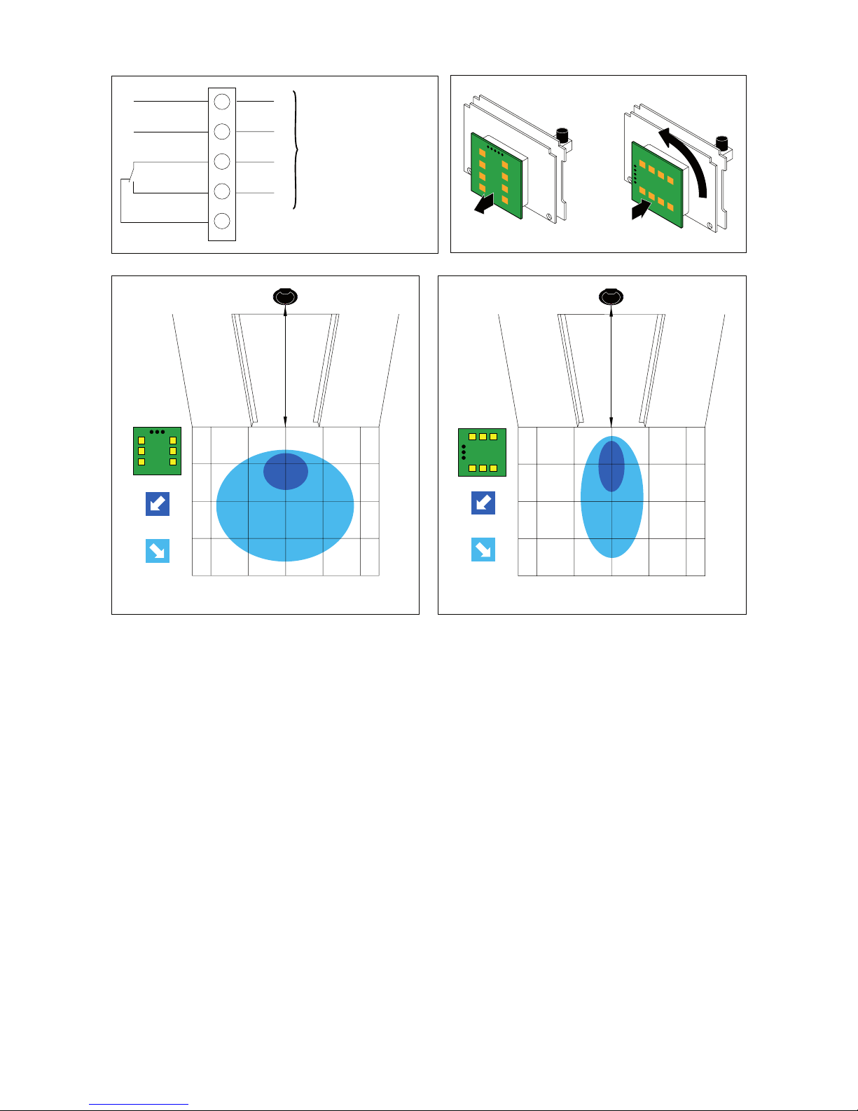
To the control panel
N.C.
24 V=
(60 mA max.)
N.O.
0
Output 30V / 1 A
1
1
3
1
2
3
4
5
Fig. 5 Fig. 6
IP2064EN - 2011-06-01
Page 3

3
DECLARATION OF CONFORMITY
Manufacturer: DITEC S.p.A.
via Mons. Ban, 3
21042 Caronno Pertusella (VA) - ITALY.
Herewith declares that the microwave sensor PASS24 is in conformity with
the provisions of the following EC directives:
- R&TTE Directive 1999/5/EC
- EMC Directive 2004/108/EC
- Low Voltage Directive 2006/95/EC.
Caronno Pertusella, 15-03-2010 Silvano Angaroni
(Managing Director)
GENERAL SAFETY PRECAUTIONS
This installation manual is intended for professionally competent personnel
only.
Read the instructions carefully before beginning to install the product. Incorrect installation may be a source of danger.
Packaging materials (plastic, polystyrene, etc.) must not be allowed to litter
the environment and must be kept out of the reach of children for whom they
may be a source of danger.
Before beginning the installation check that the product is in perfect condition.
For repairs or replacements of product only original spare parts must be
used. These instruction must be kept and forwarded to all possible future
user of the system.
To handle electronic parts, wear earthed antistatic conductive bracelets.
1. TECHNICAL DATA
Power supply 24 V=
Absorption at rest 50 mA
Absorption when detecting 80 mA
Frequency 24,125 GHz
Output contact 30 V / 1 A max (resistive load)
Protection degree IP54
Temperature from -20° C to +55°C
Max installation height 3 m
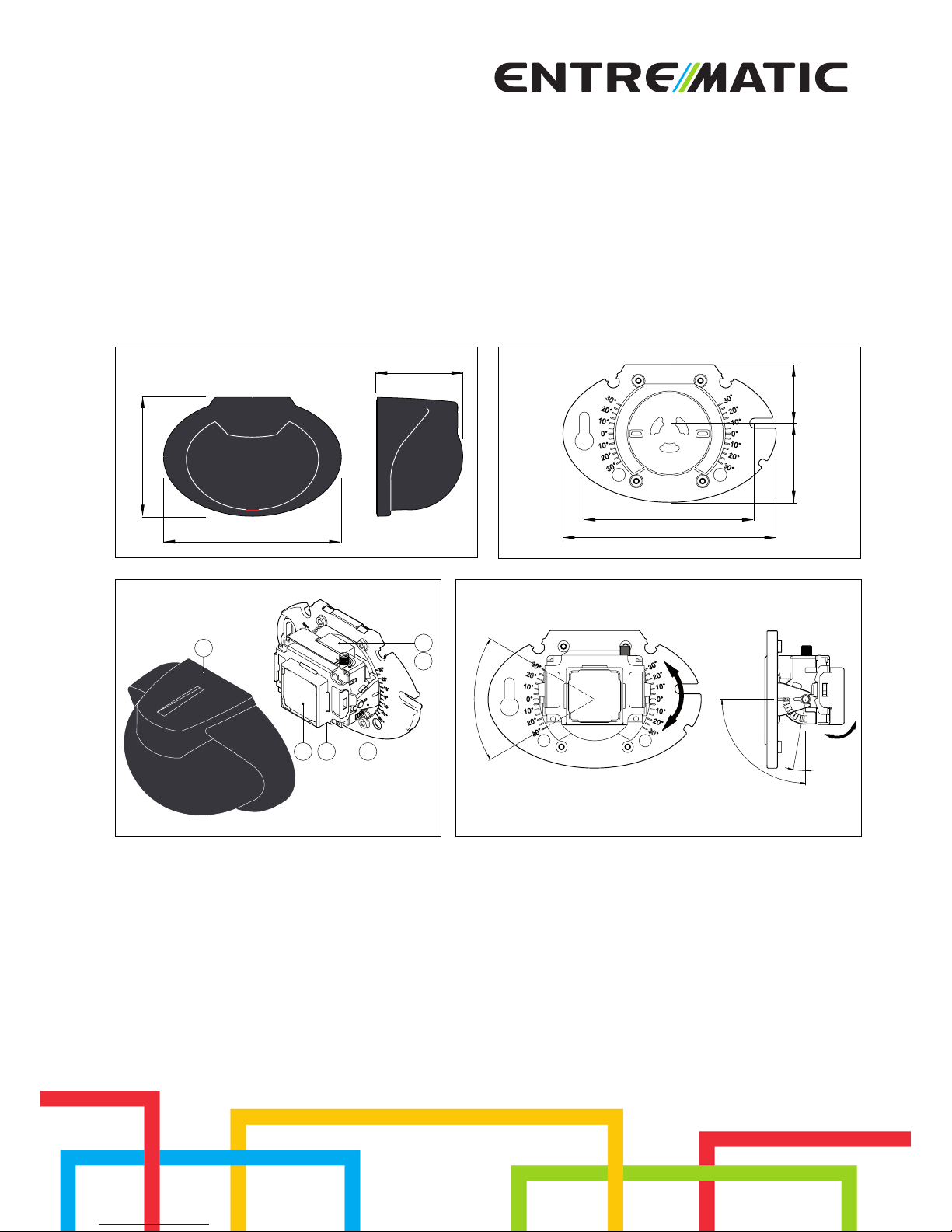
2. REFERENCE
[1] Cover
[2] Sensitivity adjustment trimmer
[3] Command terminal board
[4] Led / Operation indicator
[5] Sensor module
[6] Adjustment bracket
3. INSTALLATION AND FUNCTIONING
(Fig. 3) Remove the cover [1] by inserting a screwdriver in the hole on the
upper part of the sensor.
Securely x the sensor to a at surface using screws and plugs (not supplied)
and position it so that it can monitor the entire area opposite the passage
opening.
NOTE: avoid putting any swaying objects - such as curtains, signs or plants
- in the detection area. Ensure that rain and snow cannot fall directly onto
the sensor or it doesn’t detect them, and also that it is not directed towards
uorescent lamps.
Output
relay
N.O.
Outside the
detection area
Inside the
detection area
Outside the
detection area
Stand-by Stand-by
Motion
detection
Led
OFFOFF ON
4
4. ELECTRICAL CONNECTIONS
Make the connections indicated in g. 5.
WARNING: The product must be connected to an extra-low voltage power
source (SELV) which is protected from overcurrent and shortcircuiting.
5. ADJUSTING THE DETECTION AREAS
Selecting the type of detection area.
Choose the required form of the detection area, pointing the sensor module
[5] as indicated in gures 7 and 8.
(Fig.6) To select a restricted area, remove the sensor module cover, then
remove the sensor module [5] and rotate it by 90° anticlockwise before inserting it in the special connection.
Selecting the depth of the detection area.
The depth can be altered by changing the vertical positioning of the adjustment bracket [6]. In the examples of gures 7 and 8, the vertical angle is 30°.
NOTE: check the sensor does not detect the moving door wing.
Selecting the detection area
The position (towards the right or left) of the detection area is obtained by
rotating the adjustment bracket [6] clockwise or anticlockwise.
Adjusting the sensitivity
Adjust the sensitivity of the detection area by means of the sensitivity adjustment trimmer [2], as indicated in gures 7 and 8.
6. TROUBLESHOOTING
Problem Cause Solution
It does not work Power supply voltage Check the power supply
Faulty connection Check the wiring and the
connector
It does not
always work
Sudden change in the detection area conditions
Check the installation conditions
Check the direction of the
sensor and/or its sensitivity
It works by itself There is a moving object in
the detection area
Remove the object
Presence of water drops
on the cover.
Clean the cover and check the
sensor installation
The sensor detects
rainfalls or snowfalls
Check the installation conditions
The sensor is subject to
vibrations
Install the sensor rmly
The sensor detects the
moving door wing
Correctly adjust the detection
area and sensitivity with TR1.
All right reserved
All data and specications have been drawn up and checked with the greatest care. The manufacturer cannot however take any responsibility for
eventual errors, ommisions or incomplete data due to technical or illustrative
purposes.
IP2064EN - 2011-06-01
Page 4

IP2064EN - 2011-06-01
Entrematic Group AB
Lodjursgatan 10
SE-261 44, Landskrona
Sweden
www.ditecentrematic.com
 Loading...