

Page 1
Commercial HVLS Fans
This manual applies to fans
manufactured beginning
November 2016 with the serial
number C61174800 and higher.
Do not install, operate or service this product unless you
have read and understand the Safety Practices, Warnings,
and Installation and Operating Instructions contained in
this User’s Manual. Failure to do so could result in death
or serious injury.
User’s Manual
Installation, Operations,
Maintenance and Parts
Part No. 6020031A
Page 2
TABLE OF CONTENTS
Introduction .................................................................2
Safety Signal Words ..................................................2
Safety Practices..........................................................3
Owner’s Responsibilities ............................................4
Fan Kit ........................................................................5
Hardware ....................................................................6
Installation Considerations .........................................7
Fan Mount ..................................................................9
Components .............................................................12
Installation ................................................................13
Operating Instructions ..............................................20
Planned Maintenance ...............................................21
Troubleshooting ........................................................22
Fire Control System Fan Shutdown..........................24
Parts List...................................................................25
Warranty ...................................................................27
Distributor Information ..............................................28
INTRODUCTION
Welcome and thank you for choosing this commercial fan from Entrematic
This User's Manual contains basic information that you need to safely install and operate your fan. Please
read and keep this User's Manual before using your new fan. For more information, please consult website at
www.entrematicfans.com.
SAFETY SIGNAL WORDS
You may nd safety signal words such as DANGER, WARNING, CAUTION or NOTICE throughout this User’s
Manual. Their use is explained below:
This is the safety alert symbol. It is used
to alert you to potential personal injury
hazards. Obey all safety messages that
follow this symbol to avoid possible death or injury.
Indicates an imminently hazardous situation which,
if not avoided, will result in death or serious injury.
Indicates a potentially hazardous situation which, if
not avoided, could result in death or serious injury.
2 6020031A — Commercial HVLS Fans November 2016
© Entrematic Group AB 2015
Indicates a potentially hazardous situation which, if
not avoided may result in minor or moderate injury.
Notice is used to address practices not related to
personal injury.
Page 3

READ AND SAVE THESE INSTRUCTIONS.
READ THESE SAFETY PRACTICES BEFORE
INSTALLING, OPERATING OR SERVICING THE FAN.
Failure to follow these safety practices could result in
death or serious injury.
READ AND FOLLOW THE OPERATING INSTRUCTIONS
IN THIS MANUAL BEFORE OPERATING THE FAN. If you
do not understand the instructions, ask your supervisor
to teach you how to use the fan.
To reduce the risk of electric shock, do not expose to
water or rain.
Support directly from building structure.
SAFETY PRACTICES
Do not use this commercial fan until you have received proper
training. Improper use could result in property damage,
bodily injury and/or death. Read and follow the complete
OPERATING INSTRUCTIONS on page 20 before use. If
you do not understand the instructions, ask your supervisor
to explain them to you or call your local distributor.
DO NOT USE THE FAN IF IT APPEARS DAMAGED OR
DOES NOT OPERATE PROPERLY. Inform your supervisor
immediately.
Do not operate the fan until all personnel, building structure
and moveable equipment are clear of all moving parts. Install
guards as required.
Do not install the fan unit onto structure of insufcient
strength. Consult a professional engineer or registered
architect. Improper installation of the fan could result in
death or serious injury.
To reduce the risk of re, electric shock and injury to
persons, HVLS fan motor assemblies must be installed
with the blade assemblies that are marked on their
cartons to indicate the suitability with this model. Other
blade assemblies cannot be substituted.
To reduce the risk of re or electric shock, do not use
this fan with any solid-state speed control device
Be certain to follow the instructions in this manual.
If you do not understand the instructions, ask your
supervisor to explain them to you or call your authorized
local distributor.
To reduce the risk of injury to persons, install fan so that
the blade is at least 3.05m (10') above the oor.
INSTALLATION AND OPERATION:
Installation of the equipment must comply with local and
national electrical codes and must be in accordance with
ANSI/NFPA 70 clauses 400.7 and 400.8.
For fans that will be subjected to high cross winds (open
bay doors or air conditioning diffuser ducts) the fan must be
at least one fan diameter (as measured from the end of the
winglet) from open bays or A/C ducts mounted below the
blade plane or there must be at least one fan diameter (as
measured from the end of the winglet) for A/C ducts mounted
at or above the blade plane.
MAINTENANCE AND SERVICE:
Before service, inspection, or cleaning make certain
that the power is disconnected and properly locked off.
If the fan does not operate properly using the procedures
in this manual, BE CERTAIN TO REMOVE POWER FROM
THE UNIT AND LOCK-OUT THE DISCONNECT ON THE
POWER CIRCUIT. Call your local distributor for service.
Keep your body clear of moving parts at all times.
All electrical troubleshooting and repair must be done by a
qualied technician and meet all applicable codes.
November 2016 6020031A — Commercial HVLS Fans 3
© Entrematic Group AB 2015
Page 4

OWNER’S RESPONSIBILITIES
The owner’s responsibilities include the following:
The owner should recognize the inherent danger of the
interface between the commercial fan and shop worker. The
owner should, therefore, train and instruct operators in the
safe use of the commercial fan.
Nameplates, cautions, instructions and posted warnings shall
not be obscured from the view of operating or maintenance
personnel for whom such warnings are intended. Warnings
which are worn or non-legible should be replaced.
Manufacturer’s recommended periodic maintenance and
inspection procedures in effect at date of shipment shall be
followed, and written records of the performance of these
procedures should be kept.
Commercial fans that are structurally damaged or have
experienced impacts from external sources, shall be removed
from service, inspected by the manufacturer’s authorized
representative, and repaired as needed before being placed
back in service.
The owner shall see that all nameplates and caution and
instruction markings or labels are in place and that the
appropriate operating and maintenance manuals are provided
to users.
Modications or alterations of commercial fans shall be made
only with written permission of the original manufacturer.
4 6020031A — Commercial HVLS Fans November 2016
© Entrematic Group AB 2015
Page 5
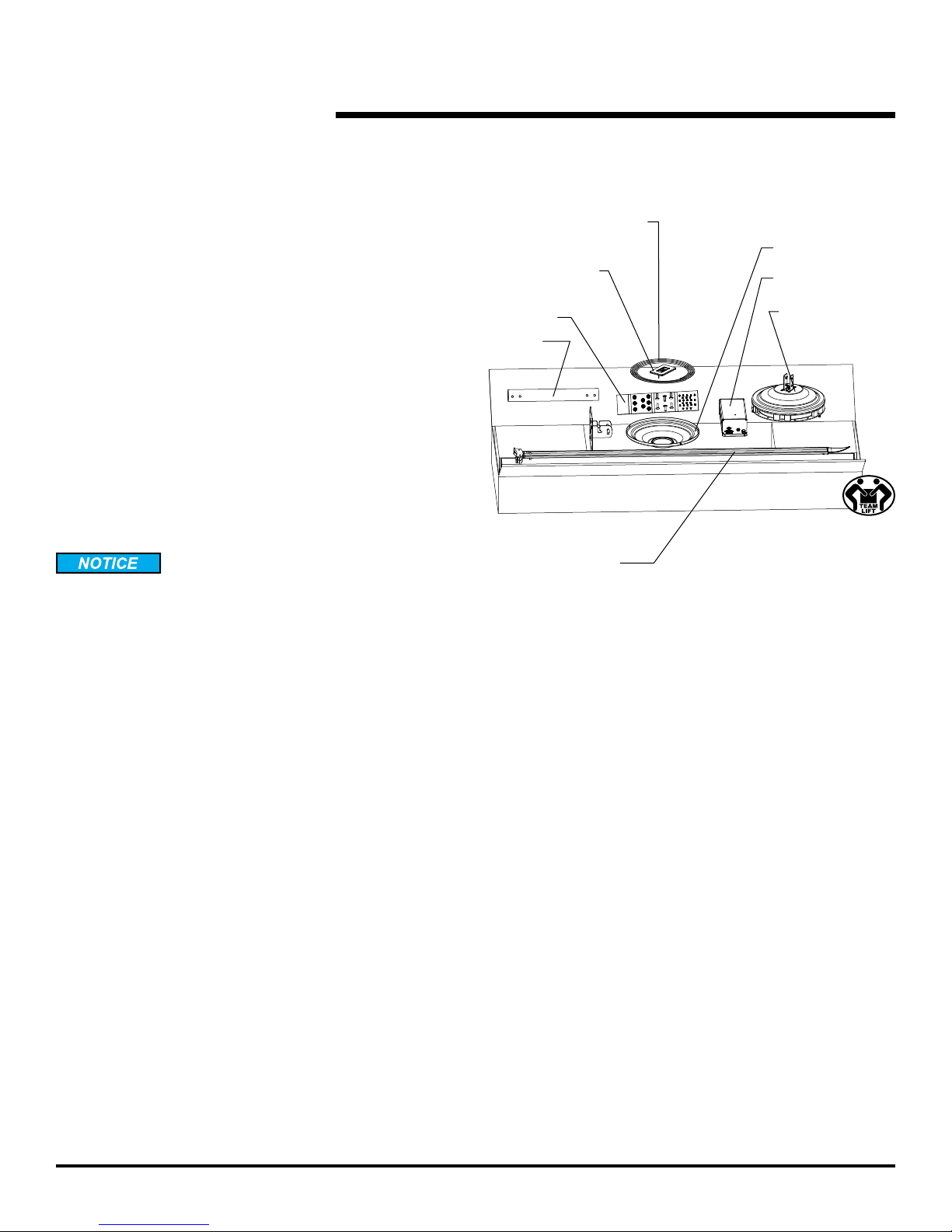
FAN KIT
PACKING KIT
1. Blade Box – 5 blades
2. Fan Motor Box
a. Motor assembly with cover.
b. Remote control.
c. Controller box.
d. Mounting hardware.
e. Power and communication cables.
REQUIRED TOOLS
• Wrenches: 9/16
• Sockets: 1/2, 9/16
• Spirit level, short
• Torque wrench: 15-60 Ft-lbs (for use with sockets)
• Tape measure
• T-15 Torx (included)
• T-40 Torx (included)
PRIOR TO FAN INSTALLATION:
1. Ensure blade length matches fan model size.
Fig. 1
Power and
communication cables
Remote control
Mounting
hardware
Down
tube
Blade assemblies
Bottom cover
Controller box
Motor assembly
with cover
3. Ensure all mounting hardware is present.
NATIONAL FIRE PROTECTION ASSOCIATION STANDARD
In accordance with NFPA 13 Standard from the National Fire
Prevention Association as referenced in sections 12.1.4 and
11.1.7: High Volume Low Speed (HVLS) Fans: The installation
of HVLS fans in buildings equipped with sprinklers, including
ESFR sprinklers, shall comply with the following:
• The maximum fan diameter shall be 14 feet (4.3 m).
• The fan shall be approximately centered between four
adjacent sprinklers.
• The vertical clearance from the fan to sprinkler deector
shall be a minimum of 3 feet (0.9 m).
• All fans shall be interlocked to shut down immediately
upon receiving a water ow signal from the alarm system
in accordance with the requirements of NFPA 72- National
Fire Alarm and Signaling Code.
November 2016 6020031A — Commercial HVLS Fans 5
© Entrematic Group AB 2015
Page 6
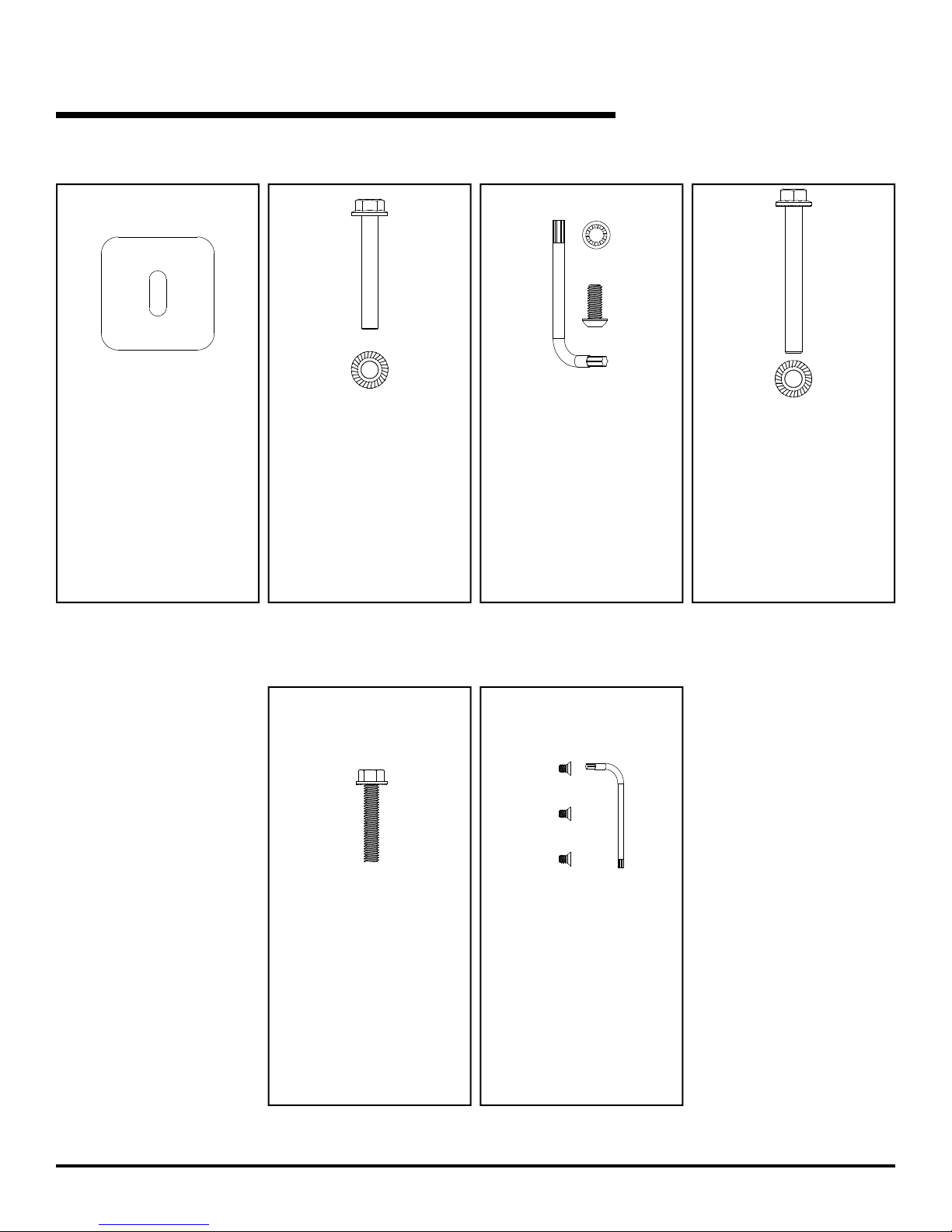
HARDWARE
Fan mount
6017852 (x4)
Clamp plate
Fan mount
6017873 (x4)
3/8-16UNC x 2-1/2" hex bolt
grade 5
serrated head
6015118 (x4)
3/8-16UNC hex nut
grade 5
serrated head
Motor mount hardware
6017838 (x4)
5/16" lock washer
6017835(x4)
5/16-18UNC x 3/4" Torx screw
grade 5
6017872 (x1)
T40 Torx wrench
Down tube mount
6017748 (x2)
3/8-16UNC x 3-1/4" hex bolt
grade 5
serrated head
6015118 (x2)
3/8-16UNC hex nut
grade 5
serrated head
Blade hardware
6017837 (x10)
5/16-18UNC x 1-3/4" hex bolt
6 6020031A — Commercial HVLS Fans November 2016
© Entrematic Group AB 2015
grade 5
serrated head
Bottom cover hardware
6017870 (x3)
8-32UNC x 1/4" Torx screw
6017871 (x1)
T15 Torx wrench
Page 7
INSTALLATION CONSIDERATIONS
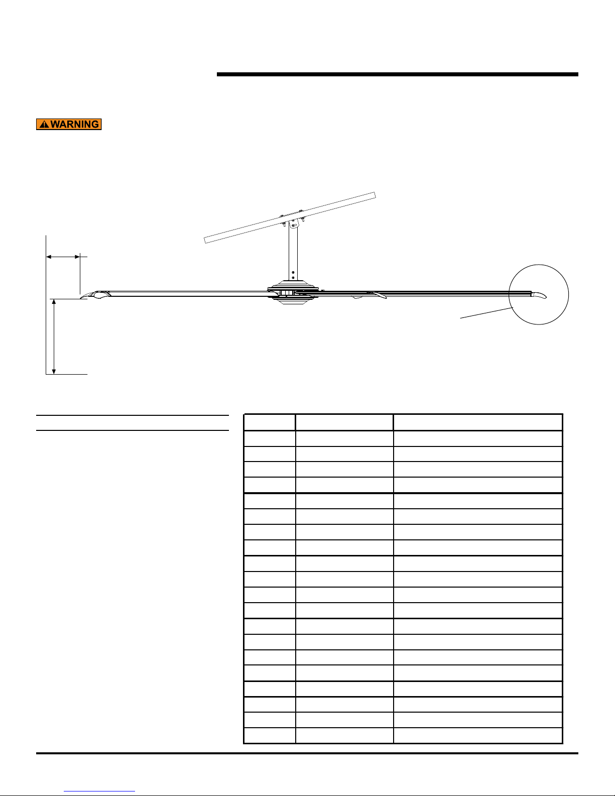
Do not mount directly under or within exclusion zone or
in line with HVAC supply discharge vent.
Fig. 2
36" min.
(to wall)
10' min.
(to floor)
36" exclusion zone
(18" radius)
[both sides]
NOTE:
Angle mount has 45° of motion. The
extension lengths shown are minimum
recommendations only, based solely of roof
pitch and fan diameter. Other considerations
must be evaluated when determining
extension requirements, such as placement
of lights, sprinkler systems, HVAC systems,
etc. In addition, OSHA requirements state
that fan blades must be a minimum of 10'
above the oor.
Fan Size Extension size (Ft) Max Roof Angle Allowable (degrees)
6Ft 1.5 17
6Ft 2 20
6Ft 3 35
6Ft 4 40
8Ft 1.5 10
8Ft 2 15
8Ft 3 25
8Ft 4 32
10Ft 1.5 10
10Ft 2 12
10Ft 3 19
10Ft 4 28
12Ft 1.5 8
12Ft 2 10
12Ft 3 17
12Ft 4 25
14Ft 1.5 6
14Ft 2 8
14Ft 3 15
14Ft 4 21
November 2016 6020031A — Commercial HVLS Fans 7
© Entrematic Group AB 2015
Page 8
INSTALLATION CONSIDERATIONS, continued
PLACEMENT AND SPACING
Consult your local distributor to help you plan the most
efcient installation of your fans.
Ensure fan placement is such that the fans blades are a
minimum of 10' from any manned working suface (oor or
mezzanine)
Ensure fan blade does not extend into exclusion zone.
Extensions are available if required. See Fig. 2.
Avoid mounting fans directly under lights or skylights to
avoid visual strobing affect.
NOTE:
If the fan is part of a networked system, ensure placement is
in accordance with the building layout.
NOTE:
Be certain to comply with all local and national codes during
installation.
For fans that will be subjected to high cross winds (open
bay doors, outdoor applications or air conditioning
diffuser ducts) the fan must be at least one fan diameter
(as measured from the end of the winglet) from open
bays or A/C ducts mounted below the blade plane or
there must be at least one fan diameter (as measured
from the end of the winglet) for A/C ducts mounted at or
above the blade plane.
In addition, all outdoor mounted fans must be protected
from exposure from the elements. Consult your local
distributor for outdoor patio applications.
8 6020031A — Commercial HVLS Fans November 2016
© Entrematic Group AB 2015
Page 9
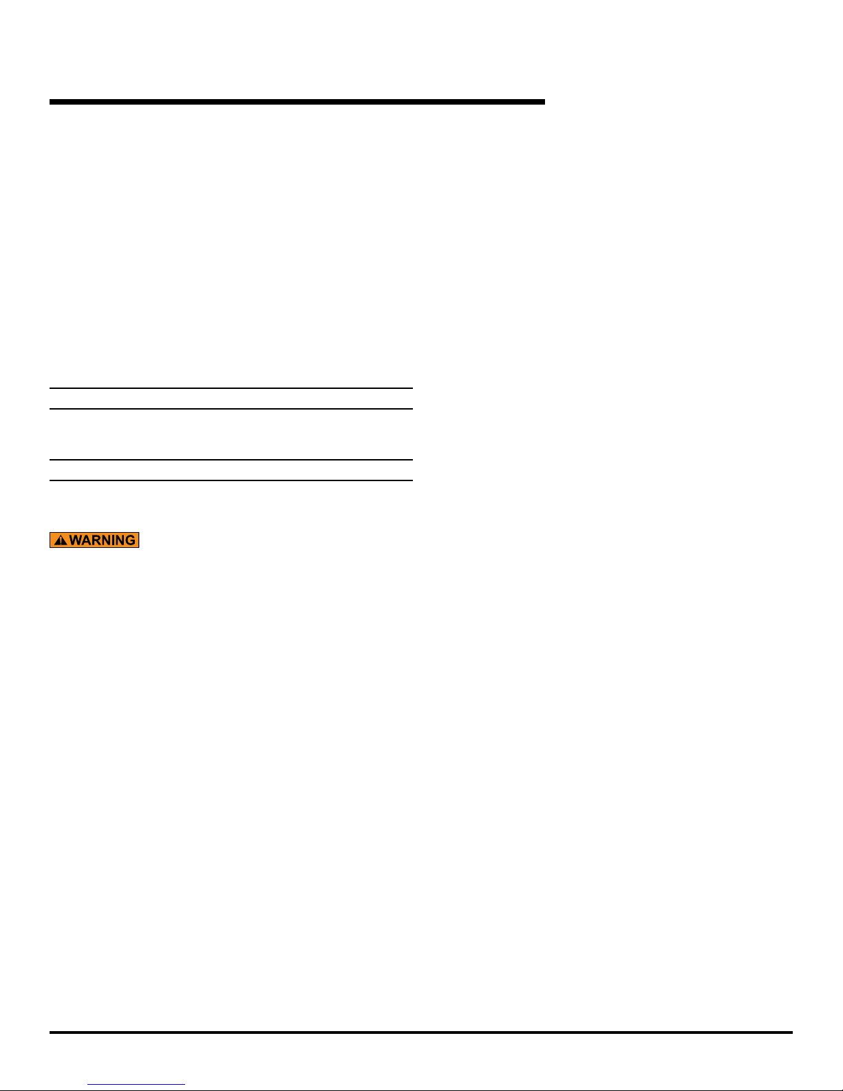
FAN MOUNT (TYPICAL MOUNTING TYPES)
I-BEAM MOUNTED
See page 9 for I-beam mounting instructions.
SOLID BEAM MOUNTED
See page 9 for solid beam mounting instructions.
I-beam
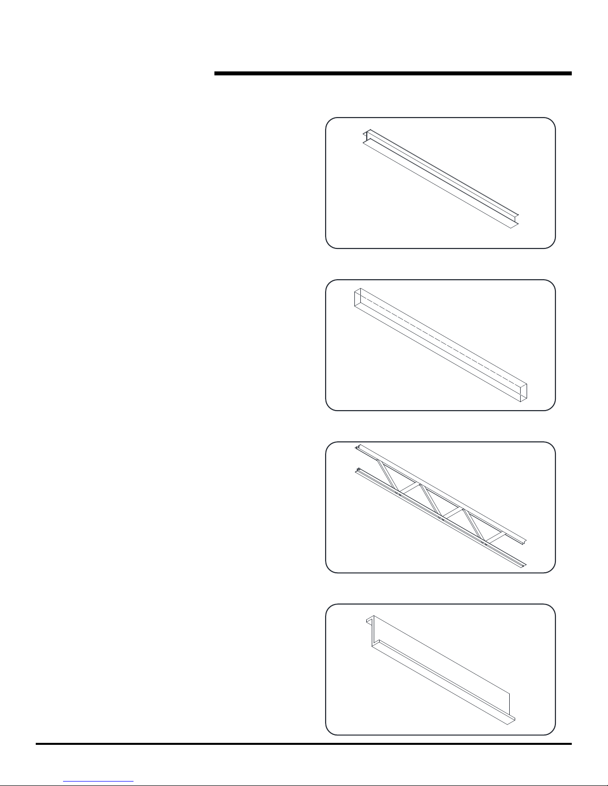
TRUSS MOUNTED
See page 10 for truss mounting instructions.
Z-PURLIN MOUNTED
See page 10 for z-purlin mounting instructions.
Solid beam
Truss
November 2016 6020031A — Commercial HVLS Fans 9
Z-purlin
© Entrematic Group AB 2015
Page 10

FAN MOUNT (TYPICAL MOUNTING TYPES), continued
Fig. 3
If building support beam is not level, ensure proper fan
clearance using the mounting information shown on
page 6 or add mounting extensions as required to ensure
clearance. See Fig 2.
I-BEAM MOUNTING
1. Locate fan centered square to the bottom ange of the
I-beam.
2. Locate and secure the clamp plates (6017852) using the
provided 3/8-16UNC hex serrated ange nuts and 3/816UNC X 2 1/2" long bolts. See Fig. 3.
NOTE:
Ensure that the clamp plates overlap the I-beam ange by
at least 30%.
3. Torque the nuts to 20-28 ft-lbs.
SOLID BEAM MOUNTING
(6018175 — CONCRETE; 6018026 — WOOD)
1. Locate the beam bracket (6018108). Ensure that the
bottom ange of the bracket is below the bottom of the
beam and square to the beam.
NOTE:
The vertical ange of the beam bracket must be square with
respect to the oor. Shim as required.
2. Using the holes in the beam bracket as a template, mark
and drill at least four (4) 9/16" dia. holes through the beam.
Space the holes as widely as practical. See Fig. 4.
3. Locate both beam brackets with respect to the holes and
fasten using 3/8" dia. grade 5 bolts (not provided). Torque
to 20-28 ft-lbs. Locking hardware (nuts and washers)
required.
Do not use lag bolt style fasteners to secure the solid
beam bracket.
Fig. 4
10 6020031A — Commercial HVLS Fans November 2016
© Entrematic Group AB 2015
Page 11

FAN MOUNT (TYPICAL MOUNTING TYPES), continued
TRUSS MOUNT INSTALLATION
NOTE:
The recommended additional structural material for truss
mounting is 1-5/8" x 1-5/8" strut channel beams and hardware.
Other structural materials may be used but consult factory
prior to use.
1. Size the strut channel beams to ensure at least 3" of
overlap at each end on adjoining building truss members.
2. Locate the mount bracket at the desired location (center
preferred) on the strut channel beams and fasten using
the provided 6017873 and 6015118 3/8" dia. grade 5
hardware. Use 6017852 clamp plates as required. Torque
to 20-28 ft-lbs.
3. Locate beam/mount assembly on building truss system.
See Fig. 5. (top mounting preferred)
4. Fasten strut channel beams to building truss system using
3.8" dia., grade 5 hardware (not provided). DO NOT use
spring loaded strut channel beam hardware. Locking
hardware (nuts and washers) required.
Fig. 5
Fig. 6
Z-PURLIN MOUNT INSTALLATION – (OPTIONAL KIT 6017945)
1. The z-purlin mounting kit is available from Entrematic.
Consult a structural engineer prior to installation.
2. Using the z-purlin backer plate as a template, locate and
mark the holes in the z-purlins for both opposing mounts.
3. Attach the z-purlin brackets to the z-purlins. Torque to
20-28 ft-lbs. See Fig. 6.
4. Cut angle irons to required length and install, spanning
the z-purlin mounts using the supplied hardware. Torque
to 20-28 ft-lbs. See Fig. 6.
5. Using the fan mount as a template, mark and drill four
7/16" dia. holes into the spanned angle irons.
6. Mount bracket to the angle irons using the supplied 3/8"
x 1" grade 5 screws and nuts. Torque to 20-28 ft-lbs. See
Fig 6.
November 2016 6020031A — Commercial HVLS Fans 11
© Entrematic Group AB 2015
Page 12

COMPONENTS
Controller box
Blade assembly
Bottom cover
Fig. 7
Fan mount
Down tube
Guy wires
(if required
see page 18)
Power/
communication
cables
Motor assembly
Remote control
12 6020031A — Commercial HVLS Fans November 2016
© Entrematic Group AB 2015
Page 13

INSTALLATION
Downtube
Downtube
DOWN TUBE ASSEMBLY
1. Route the power and communication cables through the
down tube.
2. With the down tube located next to the motor assembly,
install the cable connections to the top of the motor
assembly. See Fig 8. Use the support materials contained
in the shipping package to support motor assembly to
prevent damage.
3. Install the ground cable connector to the terminal located
on the top of the motor assembly. Ensure that the cable
is oriented to prevent interference with the down tube.
See Fig 8.
Ensure proper connection of the power and communication
cables. Failure to properly connect the cables can lead
to operating issues.
4. Slide the down tube over the motor assembly mount bracket
ensuring that the cables are not pinched or placed into a
bind. Align the down tube so that the holes in the down
tube align with the holes in the motor assembly mount
bracket.
Fig. 8
fasteners
Ensure downtube
cables are firmly
engaged
Motor
assembly
5. Attach the down tube to the motor assembly mount bracket
using the 6017838 5/16" dia. Torx screws and 6017838
washers supplied. Tighten the Torx screws using the
provided 6017872 Torx wrench.
Route ground wire
to avoid plug
Motor ground
fastener
November 2016 6020031A — Commercial HVLS Fans 13
© Entrematic Group AB 2015
Page 14

INSTALLATION, continued
communication cables
HANG THE MOTOR
1. In the top hole of the down tube, install a supplied 6017448
3/8" dia. x 3-1/4" bolt and 6015118 nut loosely. Ensure
that the screw does not pinch or bind the power and
communication cables. See Fig 9.
2. Using the bolt installed in the previous step, hang the motor
and down tube assembly on the fan mount. Ensure that
the power and communication cables are free of binding
or pinching. See Fig 10.
3. Loosely install the second 6017448 3/8" dia. x 3-1/4" bolt
and nut in the bottom hole at the top of the down tube.
Ensure that the bolt does not pinch or bind the power and
communication cables. See Fig 11.
4. Using a spirit level, ensure that the down tube is plumb.
5. Tighten the 3/8" dia x 3-1/4" bolts to 20-28 ft-lbs.
Fig. 9
Top hole
Down tube
Fig. 10
Hang down tube
from fan mount
Fig. 11
Power and
(to controller box)
Bottom hole
14 6020031A — Commercial HVLS Fans November 2016
© Entrematic Group AB 2015
Page 15

are firmly engaged.
(to building power)
CONTROLLER INSTALLATION
Building power
(from controller box)
INSTALLATION, continued
Fig. 12
Before doing any electrical work, make certain the power
is disconnected and properly tagged or locked off. All
electrical work must be done by a qualied technician
and meet all applicable codes. USE EXTREME CAUTION.
Touching wires could result in electrical shock, death or
serious injury.
On 120V fan, never allow more than 130 volts incoming
power to be connected to the controller box. Damage to
the fan and serious personal injury or death may result.
NOTE:
The controller box should be located outside of the blade arc
where possible and oriented such that the connections at
either end are accessible.
1. Install the controller box to building structure such that the
box is secure against movement. Fasteners not included.
2. Route the power and communication cables from the fan
mounting location to the controller box. Ensure that the
cables are routed clear of the fan blades and supported
throughout their run.
3. Connect the power and communication cables from the
fan to the controller box. See Fig. 12.
From fan
Ensure
cable connectors
Power cord
Fig. 13
Line
Ground
Neutral
Ensure proper connection of the power and communication
cables. Do not alter factory supplied cables. Failure to
properly connect the cables can lead to operating issues.
4. Connect controller box power cord to building power. See
Fig. 13.
NOTE:
If re alarm option is not being used, ensure re alarm jumper
is in place to ensure proper operation. See page 24.
November 2016 6020031A — Commercial HVLS Fans 15
Power cord
Fig. 14
Fire alarm jumper
© Entrematic Group AB 2015
Page 16

INSTALLATION, continued
12-17 ft-lbs.
Tang Blade pocket
INSTALL BLADES
1. Position mounting end of blade assembly in an open
blade pocket on the motor assembly rim as shown.
Angle the blade approximately 45° downward and rotated
approximately 15° forward. See Fig 15. This will position
the forward tang of the blade mount between the two steel
mount rings on the motor assembly.
2. Rotate the blade backward and upward to allow the mount
end of the blade to slide into the blade pocket on the motor
assembly rim. Position the forward tang of the mount in
the forward end of the blade pocket.
3. Rotate in the same plane as the hub to seat the blade
mount into the blade pocket.
4. Insert two 6017837 5/16" dia x 1-3/4" long fasteners
from below through the hub mount ring and blade mount.
Tighten enough to hold the blade in place but do not fully
tighten at this time.
5. Repeat installation steps 1 through 4 for each of the
remaining blades.
Fig. 15
Insert blade
tab at an angle.
6. Fully torque the blade mount fasteners to 12-17 ft-lbs.
Slide tab in
and to left.
Rotate until
blade tab
clicks in
place.
Install bolts
through
bottom of
hub and
tighten with
1/2" socket.
Torque to
16 6020031A — Commercial HVLS Fans November 2016
© Entrematic Group AB 2015
Page 17

Bottom cover
INSTALL BOTTOM COVER
1. Align the mounting holes on the bottom cover with the
mounting holes on the motor assembly. Install the three
6017870 #8 dia Torx fasteners supplied. Firmly tighten
the fasteners using the 6017871 Torx tool provided. See
Fig 16.
INSTALLATION, continued
Fig. 16
November 2016 6020031A — Commercial HVLS Fans 17
© Entrematic Group AB 2015
Page 18

thin rod provided into
the end of the clamp.
cable end.
INSTALLATION, continued
OPTIONAL GUY WIRE KIT (6016307)
NOTE:
Guy wires are required on all fan installations where the down
tube is greater than 4' in length. Guy wires are designed to
constrain lateral movement of the fan while in operation.
This movement may be due to impacts on the fan or winds
impinging on the blades that would cause the fan to sway.
Failure to attach guy wires may result in loss of warranty.
Ensure that the proper guy wire length is accompanying
the extension used. Ensure that the angle formed by the
guy wire with the roof structure is less than 45 degrees.
See Fig 17. Avoid any sharp edges or corners to reduce
fatiguing and fraying of the guy wires. Failure to attach
guy wires may result in severe injury or death.
1. Remove parts from package and inventory. Package
contents include: 4 cables, 4 gripple cable clamps, 2
5/16-18 x 1" serrated anged hex nuts, 2 guywire clamp
brackets and 1 Gripple release tool.
Fig. 17
45°
2. Locate the down tube clamp bracket on the down tube. The
clamp bracket should be located approximately halfway
between the mounting bracket and the motor assembly.
3. Fasten the halves of the down tube clamp bracket with
the 5/16" dia x 1" carriage bolts supplied. Torque to 12-17
ft-lbs.
4. Attach each cable to the building structure by either looping
the cable through the cable eyelet and around a beam/
truss or other secure building structure (preferred method)
or by using 3/8" dia. grade 5 fasteners and lock-washers
(not provided) to secure to structure. Tighten fasteners
to 20-28 ft-lbs.
5. On each cable assembly, slide one Gripple cable clamp
approximately 12" on the cable. See Fig 17.
6. Loop one cable assembly through each lug on the down
tube clamp bracket using the free end of the cable.
7. Thread the free end of each cable assembly back through
the Gripple cable clamp. Leave loose.
45°
To loosen, insert the
While gripping the
clamp and pressing
the rod into the
clamp, pull on the
18 6020031A — Commercial HVLS Fans November 2016
© Entrematic Group AB 2015
Page 19

INSTALLATION, continued
8. Using a spirit level on the down tube, tighten the cable
assemblies by pulling the cable through the Gripple
cable clamp as required to achieve a taut cable set while
maintaining the down tube plumb. Either secure the loose
cable ends or trim.
INSTALLING THE REMOTE
1. The fan remote may be mounted directly into a standard
wall junction box or directly to a wall surface using mounting
tape. Locate the remote within 50' of the fan. See Fig 18.
NOTE:
A clear sight line between the fan and the remote is preferred
in order to maximize the remote's effective distance.
Fig. 18
‘snap’
Wallplate
adapter
Wallplate
November 2016 6020031A — Commercial HVLS Fans 19
© Entrematic Group AB 2015
Page 20

OPERATING INSTRUCTIONS
and status light
Decrease speed
Before operating the fan, read and follow the Safety Practices,
Warnings and Operating Instructions in this manual. Use by
untrained personnel could result in death or serious injury.
VERIFY PRIOR TO OPERATION
1. Power supplied to fan.
2. Obstruction clearance.
3. Safety cables (optional) properly installed.
4. All fasteners are properly torqued.
Fig. 19
Green LED
Power on
STARTING THE FAN
NOTE:
Pressing the POWER ON button once, while the fan is running
will set fan to full speed.
Visually inspect the fan to ensure that there are no obstructions
or personnel in the movement area.
1. Press the FAVORITE button. The fan will start and spin
up to approximately 2/3 full speed.
2.
Adjust the speed by pressing either the INCREASE SPEED
or DECREASE SPEED buttons. Each press of the buttons
will adjust the fan speed by approximately 5%.
STOPPING THE FAN
1. Press the POWER OFF button once to stop the fan.
PROGRAMMING THE FAVORITE BUTTON
NOTE:
The fan ships from the factory with the FAVORITE button
pre-programmed to approximately 2/3 full speed.
Increase speed
Favorite button
Power off
Fig. 20
1. With the fan running, adjust the speed of the fan using
either the INCREASE SPEED or DECREASE SPEED
button to achieve desired speed. See Fig. 19.
2. Once desired speed is achieved, press and hold the
FAVORITE button for 10 seconds. This speed now
becomes the new FAVORITE speed.
CHANGING DIRECTION
1. The fan direction control is located on the top of the motor
assembly. To reverse direction, stop the fan and press the
button. See Fig. 20.
20 6020031A — Commercial HVLS Fans November 2016
© Entrematic Group AB 2015
Fan direction control
Page 21

Before service, inspection, or cleaning make certain that
the power is disconnected and properly locked off.
Before servicing the fan, read and follow the Safety
Practices on page 3 and the Operation section in this
manual. Failure to do so could result in death or serious
injury.
To ensure the continued proper operation of your fan,
perform the following planned maintenance procedures.
Fig. 21
PLANNED MAINTENANCE
ANNUALLY
1. Inspect blade mounting hardware and tighten as required.
Torque to 20-28 ft-lbs.
2. Inspect guy wires for chafng or wear. Ensure wires are
taut. Re-tighten cables as required and ensure all cable
mounting hardware is secure. Maintain plumb attitude of
downtube. Torque to 12-17 ft-lbs.
3. Inspect fan blades and winglets. Clean fan blades as
required. Use a soft dry cloth. If necessary, use a mild
detergent to clean surfaces. Do not use harsh cleansers.
Legend
Symbol
Description
Cleaning
(Location - Frequency)
Visually Inspect
(Replace Damaged Or Worn)
Check Fasteners
(Torque to spec. if necessary)
November 2016 6020031A — Commercial HVLS Fans 21
© Entrematic Group AB 2015
Page 22

TROUBLESHOOTING
Before servicing the fan, read and follow the Safety
Practices on page 3 and the Operation section in this
manual. Failure to do so could result in death or serious
injury.
Use the Troubleshooting Guide if the fan fails to perform
properly. Find the condition that most closely matches your
situation and make the recommended adjustments.
Problem Possible Cause Solution
1. No blue light, no fan movement
a) No power to fan
b) Circuit breaker on controller
box tripped
c) Communication cable loose
d) Remote is not programmed
e) Bad remote
f) Issue inside controller box
Before service, inspection, or cleaning make certain that
the power is disconnected and properly locked off.
Before doing any electrical work, make certain the power
is disconnected and properly locked or tagged off. Failure
to do so may result in death or serious injury. All electrical
troubleshooting and repair must be done by a qualied
technician and meet all applicable codes. Failure to do so
could result in electrical shock, death or serious injury.
a) Check incoming power
b) Reset circuit breaker See Fig. 22.
c) Ensure communication cable is rmly
attached at each end.
d) Program remote. See page 23.
e) Replace and program new remote
f) Consult technical service
2.
Fast blink (approx. 2 blinks/sec.)
blue light, no fan movement
3. Fast blink blue light, fan
movement.
4. Slow blink blue light, no
movement
5. Solid blue light, sustained
shuddering movement
6. Fan runs but makes noise or
vibrates
a) Power cable loose
a) Bad communication cable
b) Encoder cable loose
c) Motor power lead loose
d) Issue inside controller box
a) Fire alarm jumper issue
a) Issue inside controller box
a) Bad motor bearing
b) Missing or damaged winglet
c) Loose or damaged blade
d) Loose or damaged guy
wires
a) Ensure power cable is rmly attached at
each end
a) Replace cable
b) Consult technical service
c) Consult technical service
d) Consult technical service
a) Ensure jumper wire is in place
a) Consult technical service
a) Check if fan rotates freely by hand
without binding
b) Check winglets
c) Ensure blades are rmly attached and
mounting fasteners are tight
d) Ensure guy wires are taut and properly
installed
22 6020031A — Commercial HVLS Fans November 2016
© Entrematic Group AB 2015
Page 23

TROUBLESHOOTING, continued
Controller box
Green LED
PROGRAMMING THE REMOTE
NOTE:
The fan ships from the factory with the remote pre-programmed
and ready to use. To program or reprogram the remote, access
to the controller box will be required. Ensure that the fan is
not running and there is power to the controller box.
1. Locate the controller box and ensure that there is access
to the top cover.
2. On the top cover, locate the remote program access hole.
See Fig 22.
3. With a small dowel or other blunt object, gently depress
the programming button for 10 seconds.
4. On the remote, press and hold the power off button for 6
seconds. Release the button when the green LED on the
remote begins to ash to show that the wireless remote
has been associated with the controller. See Fig 23.
CHANGING THE BATTERY IN THE REMOTE
Fig. 22
Fig. 23
Circuit breaker
Program
access hole
Power off
Burn hazard. To avoid the risk of re, explosion or burns, DO
NOT recharge, disassemble, crush, puncture or incinerate
the battery. DO NOT heat the battery above 212°F (100°C).
NOTE:
A dead battery must be replaced promptly in order to retain
programming.
1. Remove the wireless remote from the faceplate assembly.
2. Place a athead screwdriver into the slot at the bottom of
3. Slide the battery out, toward the top of the remote.
4. Slide a new CR 2032 battery underneath the contact strap,
5. Replace the back enclosure.
6. Ensure proper fan operation. If the remote fails to control
Fig. 24
the remote. Twist to open. DO NOT press buttons without
back enclosure on. See Fig. 24.
with the (-) terminal toward the front of the remote.
the fan, re-program the remote using the process described
above.
7. Re-install remote into faceplate as required.
November 2016 6020031A — Commercial HVLS Fans 23
© Entrematic Group AB 2015
Page 24

FIRE CONTROL SYSTEM FAN SHUTDOWN — OPTIONAL
This fan includes a re alarm jumper for a building re control
systems option that allows the fan to be shut down by the re
control system in case of a re emergency.
NOTE:
Ensure that the re alarm jumper is in place or the building
re control system is connected and jumper removed.
1. The normally closed (NC) contacts must be dry contacts.
They open in the event of an active re alarm.
2. The re control system fan shutdown option is not
enabled when shipped. To enable the re control system
fan shutdown option, remove jumper and route a pair of
conductors to a set of customer supplied N.C. contacts
in the building's re alarm panel. See Fig. 25.
3. To test the re control system fan shutdown operation
remove the wire from the NC contact at the building re
control panel. The fan should coast to a stop.
If the jumper is left installed the fan will not shut down
due to re control system contacts.
Fig. 25
Fire alarm jumper
24 6020031A — Commercial HVLS Fans November 2016
© Entrematic Group AB 2015
Page 25

PARTS LIST
Fig. 26
2
1
To ensure proper function, durability and safety of the
product, only replacement parts that do not interfere with
the safe, normal operation of the product must be used.
Incorporation of replacement parts or modications that
weaken the structural integrity of the product, or in any
way alter the product from its normal working condition
at the time of purchase from Entrematic may result in
product malfunction, breakdown, premature wear, death
or serious injury.
4
11
3
8
12
10
9
21
November 2016 6020031A — Commercial HVLS Fans 25
18
14
22
7
6
13
5
17
20
19
15
© Entrematic Group AB 2015
16
Page 26

PARTS LIST
Item Quantity Description Part Number
1 1 MOUNT, 45° 6018002
2* 1 UPPER COVER - SILVER 6016269
3* 1 LOWER COVER - SILVER 6017786
4 1 CONTROLLER CONSULT FACTORY
5 1 POWER CABLES - 132" 6016279
6 1 CONTROL CABLES - 132" 6017645
7 1 CONCRETE BEAM MOUNT — OPTIONAL 6018175
8* 1 DOWN TUBE - SILVER - 18" 6017726
9* 1 BLADE ASSEMBLY — 6FT - SILVER 6017580
BLADE ASSEMBLY — 8FT - SILVER 6017581
BLADE ASSEMBLY — 10FT - SILVER 6017582
BLADE ASSEMBLY — 12FT - SILVER 6017583
BLADE ASSEMBLY — 14FT - SILVER 6017584
10 1 REMOTE CONSULT FACTORY
11 1 MOTOR ASSEMBLY 6016280
12 1 CEILING COVER PLATE 6017848
13 1 WOOD BEAM CLAMP — OPTIONAL 6018026
14 1 EXTENSION GUY WIRE KIT, 3-5' 6016307
EXTENSION GUY WIRE KIT, 6-10' 6017765
EXTENSION GUY WIRE KIT, 11-15' 6017766
15 2 3/8-16UNC X 3 1/4", FLNG SERTD HEX BOLT, GRD-5 6017748
16 3 8-32UNC X1/4 LG FLT HD SCREW-TORX, ZP 6017870
17 10 5/16-18UNC X 1 3/4", FLGD SRTD HEX BOLT,GRD-5, ZP 6017837
18 6 3/8-16UNC HEX SERRATED FLANGE NUT 6015118
19 4 5/16-18UNC X 3/4 LG TORX SOC HD SCREW, GRD 2, ZP 6017835
20 4 5/16 INT TOOTH LOCK WASHER 6017838
21 4 CLAMP PLATE, COMM FAN 6017852
22 4 3/8-16UNC X 2 1/2", FLNG SERTD HEX BOLT, GRD-5 6017873
*Consult factory for colors other than silver.
26 6020031A — Commercial HVLS Fans November 2016
© Entrematic Group AB 2015
Page 27

WARRANTY
THIS LIMITED WARRANTY IS ENTREMATIC’S SOLE AND EXCLUSIVE WARRANTY WITH RESPECT TO THE HVLS
FAN AND IS IN LIEU OF ANY OTHER GUARANTEES OR WARRANTIES, EXPRESS OR IMPLIED. THIS LIMITED
WARRANTY APPLIES ONLY TO THE ORIGINAL PURCHASER OF THE HVLS FAN AND CANNOT BE TRANSFERRED.
ENTREMATIC warrants that this HVLS FAN will be free from aws in material and workmanship under normal use for a
period of one (1) year from the earlier of 1) 60 days after the date of initial shipment by ENTREMATIC, or 2) the date of
installation of the HVLS FAN by the original purchaser, provided that the owner maintains and operates the HVLS FAN in
accordance with this User's Manual.
In the event that this HVLS FAN proves decient in material or workmanship within the applicable Limited Warranty period,
owner shall so notify ENTREMATIC, and Entrematic will, at its option:
1. Replace the HVLS FAN, or the decient portion(s) thereof, without charge to the owner; or
2. Alter or repair the HVLS FAN, on site or elsewhere, without charge to the owner.
In addition, ENTREMATIC warrants the HVLS FAN for an additional nine (9) years for replacement parts only.
This Limited Warranty does not cover any failure caused by improper installation, abuse, improper operation,
negligence, or failure to maintain and adjust the HVLS FAN properly. Parts requiring replacement due to damage
resulting from impact, abuse, or improper operation are not covered by this warranty. ENTREMATIC DISCLAIMS ANY
RESPONSIBILITY OR LIABILITY FOR ANY LOSS OR DAMAGE OF ANY KIND (INCLUDING WITHOUT LIMITATION,
DIRECT, INDIRECT, CONSEQUENTIAL OR PUNITIVE DAMAGES, OR LOST PROFITS OR LOST PRODUCTION)
arising out of or related to the use, installation or maintenance of the HVLS FAN (including premature product
wear, product failure, property damage or bodily injury resulting from use of unauthorized replacement parts or
modication of the HVLS FAN). ENTREMATIC’s sole obligation with regard to a HVLS FAN that is claimed to be
decient in material or workmanship shall be as set forth in this Limited Warranty. This Limited
Warranty will be null and void if the original purchaser does not notify ENTREMATIC’s warranty department within
ninety (90) days after the product deciency is discovered.
THERE ARE NO WARRANTIES, EXPRESS OR IMPLIED, WHICH EXTEND BEYOND THE DESCRIPTION ON THE
FACE HEREOF, INCLUDING, BUT NOT LIMITED TO, A WARRANTY OF MERCHANTABILITY OR OF FITNESS FOR A
PARTICULAR PURPOSE, ALL OF WHICH ENTREMATIC HEREBY DISCLAIMS.
November 2016 6020031A — Commercial HVLS Fans 27
© Entrematic Group AB 2015
Page 28

Please direct questions about your fan to your local distributor.
Your local distributor is:
Corporate Head Ofce:
1612 Hutton Dr. Suite 140
Carrollton, TX. 75006
Tel. 1-972-466-0707
Fax 1-972-323-2661
Part No. 6020031A© Entrematic Group AB 2015
 Loading...