

Page 1
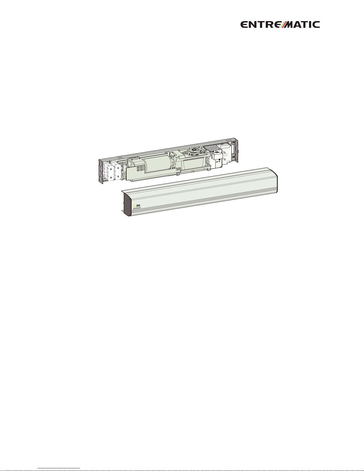
Swing Door Operator
EM EMSW EMO
ILL-01780
Installation and Service Manual
Original instructions
1005088-EMEI-16.0 – Issue 2016-10-24
Page 2

© All rights in and to this material are the sole property of Entrematic Nordic AB. Copying, scanning, alterations or modifications are
expressly forbidden without the prior written consent of Entrematic Nordic AB. Rights reserved for changes without prior notice.
Backtrack information: folder:Workspace Main, version:a356, Date:2016-10-24 time:10:35:20, state: Frozen
Page 3

CONTENTS - Original instructions
51 Revision .....................................................................................................................................................................................
62 Instructions for safe operation ...........................................................................................................................................
73 Important information .........................................................................................................................................................
73.1 Intended use ....................................................................................................................................................................................
73.2 Safety precautions .........................................................................................................................................................................
73.3 Electronic equipment reception interference .....................................................................................................................
83.4 Environmental requirements .....................................................................................................................................................
94 Technical specifications ........................................................................................................................................................
104.1 Permitted door weight and door width ................................................................................................................................
115 How the EM EMSW EMO works .........................................................................................................................................
115.1 Opening ............................................................................................................................................................................................
115.2 Closing ...............................................................................................................................................................................................
115.3 Functions on the basic control unit CU-ESD .........................................................................................................................
115.3.1 Power failure ..................................................................................................................................................................
115.3.2 Spring force ....................................................................................................................................................................
115.3.3 Extended closing force/torque (CLTQ) ..................................................................................................................
115.3.4 Power assist (POAS) .....................................................................................................................................................
115.3.5 Push and go (PAG) ........................................................................................................................................................
115.3.6 Overhead presence detector (OPD), frame mounted .....................................................................................
125.3.7 Mat ....................................................................................................................................................................................
125.4 Functions on the extension unit EXU-SI .................................................................................................................................
125.4.1 KILL function ..................................................................................................................................................................
125.4.2 Function of locks ...........................................................................................................................................................
125.4.3 Program selector ..........................................................................................................................................................
125.4.4 Impulses ..........................................................................................................................................................................
135.4.5 OPEN/CLOSE impulse ..................................................................................................................................................
135.4.6 Power failure mode (backup batteries are installed) – optional ..................................................................
135.4.7 Nurse and bed functionality .....................................................................................................................................
135.5 Functions on the extension unit EXU-SA – optional ...........................................................................................................
135.5.1 Presence impulse approach, door mounted .......................................................................................................
145.5.2 Presence detection swingpath, door mounted ..................................................................................................
145.5.3 Monitored safety sensors ...........................................................................................................................................
145.5.4 Open door indication ..................................................................................................................................................
145.5.5 Error indication .............................................................................................................................................................
156 Models ........................................................................................................................................................................................
156.1 EM EMSW EMO, standard cover (wall mounted) ................................................................................................................
167 Part identification & Accessories ......................................................................................................................................
177.1 Arm system, PUSH .........................................................................................................................................................................
177.1.1 PUSH-arm extensions .................................................................................................................................................
177.2 Arm system, PUSH-335 ................................................................................................................................................................
177.3 Arm system, PULL ...........................................................................................................................................................................
187.4 Arm system, PULL-220 .................................................................................................................................................................
187.5 Arm system, ST-V / ST-H ...............................................................................................................................................................
187.5.1 Options for ST-V / ST-H ................................................................................................................................................
187.6 Reveal spacer: PULL / PULL-220 .................................................................................................................................................
197.7 20 mm extension ...........................................................................................................................................................................
197.8 Drive shaft extension kits ............................................................................................................................................................
207.9 Control switches ............................................................................................................................................................................
207.9.1 Power ON/OFF switch .................................................................................................................................................
207.9.2 ON/OFF/HOLD open switch (will not operate electric lock) ..........................................................................
207.9.3 4-position switch PS-4C (operates the electric lock) .......................................................................................
217.10 Sync cable for double doors (synchronizing of 2 operators) ..........................................................................................
237.11 Extension units ................................................................................................................................................................................
237.12 Battery backup unit .......................................................................................................................................................................
247.13 Cover piece kit ................................................................................................................................................................................
247.13.1 Middle piece kit .............................................................................................................................................................
247.14 Labels .................................................................................................................................................................................................
3Issue 2016-10-241005088-EMEI-16.0
Page 4

258 Pre-installation ........................................................................................................................................................................
258.1 General tips/Safety concerns .....................................................................................................................................................
258.2 Operator/Door handing ...............................................................................................................................................................
268.3 Installation examples ....................................................................................................................................................................
268.4 Fastening requirements (but not included) .........................................................................................................................
278.5 Tools required .................................................................................................................................................................................
278.6 Installation on double doors ......................................................................................................................................................
289 Mechanical installation ........................................................................................................................................................
289.1 Operator with PUSH arm system ..............................................................................................................................................
349.2 Operator with PULL arm system ...............................................................................................................................................
409.3 Installation of operator with arm system ST .........................................................................................................................
4910 Electrical connection .............................................................................................................................................................
4910.1 Mains connection ..........................................................................................................................................................................
5010.2 Control units ....................................................................................................................................................................................
5010.2.1 CU-ESD .............................................................................................................................................................................
5010.2.2 Arm system selection ..................................................................................................................................................
5110.2.3 Extension units EXU-SI / EXU-SA ..............................................................................................................................
5210.2.4 Extension unit EXU-SI ..................................................................................................................................................
5310.2.5 Extension unit EXU-SA ................................................................................................................................................
5410.3 Sensor cable inlet ...........................................................................................................................................................................
5511 Start-up ......................................................................................................................................................................................
5511.1 Adjusting the door stop ...............................................................................................................................................................
5711.2 Auto-learn – automatically sets back and latch check (recommended) .....................................................................
5711.2.1 One push / two pushes on the LEARN BUTTON (LRN) .....................................................................................
5711.2.2 Double doors .................................................................................................................................................................
5811.3 General adjustment ......................................................................................................................................................................
5911.4 Connection of activation units and accessories ..................................................................................................................
6012 Cover ..........................................................................................................................................................................................
6012.1 Fitting and removing the cover .................................................................................................................................................
6112.2 Middle piece cover ........................................................................................................................................................................
6213 Signage .......................................................................................................................................................................................
6314 Advanced settings ..................................................................................................................................................................
6314.1 Learn with advanced setting of “back- and latch-check” ..................................................................................................
6314.2 Revert to default values for “back- and latch-check" (Level 1) .......................................................................................
6414.3 Changing group of parameters (Level 2) ...............................................................................................................................
6514.4 Classification (Level 3) ..................................................................................................................................................................
6614.5 Overhead Presence Detection (OPD) Monitoring (Level 4) ............................................................................................
6714.6 Lock kick (Level 5) ..........................................................................................................................................................................
6714.7 Lock unlocked status (Level 6) ..................................................................................................................................................
6815 Reducing / Increasing the “Spring pre-tension” (SPTE) .............................................................................................
6916 Installation and adjustments ..............................................................................................................................................
6916.1 Complementary Safety Devices Swing Doors ......................................................................................................................
6916.2 Swing Doors Opening and Closing Time ................................................................................................................................
6916.2.1 How to find the correct opening and closing time ...........................................................................................
7016.3 Diagrams for Door weight ..........................................................................................................................................................
7016.3.1 Aluminium frame with glass .....................................................................................................................................
7117 Troubleshooting .....................................................................................................................................................................
7217.1 Error indication ...............................................................................................................................................................................
7318 Service / Maintenance ...........................................................................................................................................................
1005088-EMEI-16.0Issue 2016-10-244
Page 5

1 Revision
The following pages have been revised:
Revision 15.0 → 16.0Page
Updated.53
Added this new section.54
5Issue 2016-10-241005088-EMEI-16.0
1 Revision
Page 6

2 Instructions for safe operation
• Failure to observe the information in this manual may result in
personal injury or damage to equipment.
• Toreduce the risk of injury to persons - use this operator with single
or double pedestrian swinging or folding doors only.
• Do not use the equipment if repair or adjustment is necessary.
• Disconnect supply when cleaning or other maintenance is to be
carried out.
• The operator can be used by children age 8 and above, and persons
with reduced physical, sensory or mental capabilities, or lack of experience and knowledge, if they have been given supervision or instruction by a person responsible for their safety concerning safe
operator use and the possible hazards involved.
This does not however prevent those persons to use the door where
the operator is installed.
• Cleaning and user maintenance shall not be made by children
without supervision.
• Do not let children climb on or play with the door or the fixed/remote controls.
• Risk of battery explosion if wrong type of battery is used.
• In all instances, where work is being done, the area is to be secured
from pedestrian traffic, and the power removed to prevent injury.
• The doorset can be operated automatically by sensors or manually
by activators. It can also be used manually as a door closer.
1005088-EMEI-16.0Issue 2016-10-246
2 Instructions for safe operation
Page 7

3 Important information
3.1 Intended use
The door is designed to offer continuous use, a high degree of safety and maximum lifetime. The
system is self-adjusting to the effects caused by normal variations in the weather conditions and
to minor friction changes caused by e.g. dust and dirt.
For escape in emergency situations the doorset is opened manually.
This manual contains the necessary details and instructions for the installation, maintenance and
service of the Swing Door Operator EM EMSW EMO.
The EM EMSW EMO is an automatic swing door operator developed to facilitate entrances to
buildings and within buildings through swing doors. The EM EMSW EMO is a low-energy operator
using a DC motor and a gear-reduction system to drive an arm system, which opens the door. It is
to be installed indoors where it is suitable for almost all types of external and internal swing doors.
This widely-used operatorcanbe found on applications ranging from handicapped-access in private
homes to high-traffic retail operations.
The motor and gear system are combined into a compact unit mounted alongside the control unit
within the cover. The operator is connected to the door leaf with different arm systems.
For use see User manual 1005099.
Save these instructions for future reference.
3.2 Safety precautions
Be sure to complete a risk assessment and site acceptance test before taking the door into operation.
To avoid bodily injury,material damage and malfunction of the product, the instructions contained
in this manual must be strictly observed during installation, adjustment, repairs and service etc.
Training is needed to carry out these tasks safely.Only Entrematic Nordic-trained technicians should
be allowed to carry out these operations.
3.3 Electronic equipment reception interference
The equipment complies with the European EMC directive (US market FCC Part 15), provided installed according to Installation and Service manual.
The equipment may generate and use radio frequency energy and if not installed and used properly,
it may cause interference to radio, television reception or other radio frequency type systems.
If other equipment does not fully comply with immunity requirements interference may occur.
There is no guarantee that interference will not occur in a particular installation. If this equipment
does cause interference to radio or television reception, which can be determined by turning the
equipment off and on, the user is encouraged to try to correct the interference by one or more of
the following measures:
• Re-orient the receiving antenna.
• Relocate the receiver with respect to the equipment.
• Move the receiver away from the equipment.
• Plug the receiver into a different outlet so that equipment and receiver are on different branch
circuits.
• Check that protective earth (PE) is connected.
If necessary, the user should consult the dealer or an experienced electronics technician for additional suggestions.
7Issue 2016-10-241005088-EMEI-16.0
3 Important information
Page 8

3.4 Environmental requirements
Entrematic Nordic products are equipped with electronics and may also be equipped with batteries
containing materials which are hazardous to the environment. Disconnect power before removing
electronics and battery and make sure it is disposed of properly according to local regulations (how
and where) as was done with the packaging material.
1005088-EMEI-16.0Issue 2016-10-248
3 Important information
Page 9

4 Technical specifications
Ensure that the door operator with technical specification below is suitable for the installation.
Entrematic Nordic ABManufacturer:
Lodjursgatan 10, SE-261 44 Landskrona, SwedenAddress:
EM EMSW EMOType:
100-240 V AC +10/-15%, 50/60 Hz, mains fuse max 10A (building
installation)
Mains supply:
Note! The mains supply shall be installed with protection and an
all-pole mains switch with isolating capability of Category III, at least
3 mm between contacts, shall be installed according to local regulations. These articles are not provided with the door.
Max. 75 WPower consumption:
24 V DC, max. 400 mAAuxiliary voltage:
2 x T 6,3 AH/250 VMains fuse F1, F2:
PUSH arm system; size 4Door size:
PULL arm system; size 1
ST-V/H arm system; size 3
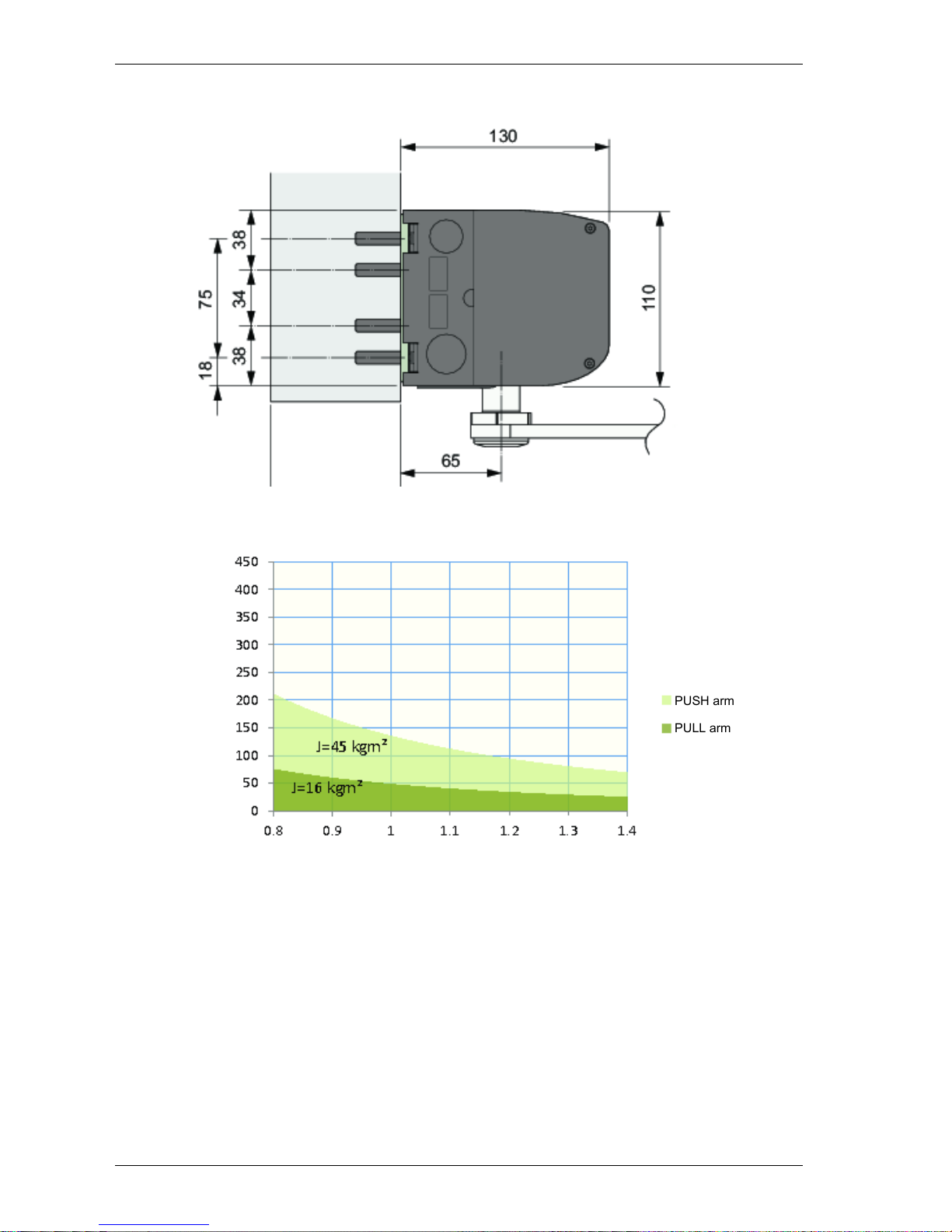
For PUSH = 45 kgm
2
Max. Inertia J:
For PULL = 16 kgm
2
Inertia = Door weight x (Door width)2/ 3
The EM EMSW EMO complies with the door weights/widths stated
in the:
Controlled door closing, EN 1154 Table I, size 4
Selectable: 12V DC, max. 500 mA or 24 V DC, max. 250 mAElectro-mechanical locking
device:
PUSH arm: 80° - 110°, with reveal 0 - 305 mmDoor opening angle:
PULL arm: 80° - 110°, with reveal -20 - 130 mm
Variable between 3 - 6 secondsOpening time (0° - 80°):
Variable between 3 - 6 secondsClosing time (90° - 10°):
1.5 - 30 secondsHOLD open time:
-20 °C to +45 °CAmbient temperature:
Max. 85%Relative humidity:
7.1 kgDrive unit weight:
IP20Class of protection:
IP54Degree of protection, con-
trol actuators:
Third party approvals from established certification organizations
valid for safety in use, see Declaration of Incorporation.
Approvals:
9Issue 2016-10-241005088-EMEI-16.0
4 Technical specifications
Page 10
This product is to be installed internally.
4.1 Permitted door weight and door width
PUSH arm
PULL arm
Door weight (kg)
Door width (m)
1005088-EMEI-16.0Issue 2016-10-2410
4 Technical specifications
Page 11

5 How the EM EMSW EMO works
The swing door operator EM EMSW EMO uses a DC motor and a gear-reduction system to drive an
arm system, which opens the door. Closing power is provided by a motor and a clock spring. An
electronic control unit uses a motor encoder and a microprocessor to control the door’s movement.
5.1 Opening
When an opening signal is received by the control unit, the door is opened at the operator-adjusted
opening speed. Before the door is fully open at back check, it slows automatically to low speed.
The motor stops when the selected door opening angle has been reached. The open position is
held by the motor.
If the door is obstructed while opening, it will either stall or stop which can be selected with a DIPswitch (SOS). Stop on stall is always active in program selector Mode Off.
• Continue on stall - the door will continue to try to open during the hold open time.
• Stop on stall - the door will, even if hold open time has not expired, close after 2 seconds.
5.2 Closing
When the hold open time has elapsed, the operator will close the door automatically, using spring
force and motor. The door will slow to low speed at latch check before it reaches the fully closed
position. The door is kept closed by spring power or combined with extended closing torque by
the motor.
5.3 Functions on the basic control unit CU-ESD
Also see page 50 for more information.
5.3.1 Power failure
During power failure the operator acts as a door closer with controlled closing speed.
5.3.2 Spring force
The operator is delivered with spring pre-tension factory set to 210°. If necessary, the spring tension
can be electronically adjusted with a potentiometer to required closing force.
5.3.3 Extended closing force/torque (CLTQ)
If the potentiometer CLTQ is set to 0°, the door will close with normal spring power. If the potentiometer is turned clockwise, the motor will increase the closing force/torque.
5.3.4 Power assist (POAS)
If the potentiometer POAS is set to 0°, the door gives no power assist. If the potentiometer is turned
clockwise, the motor will give/increase power assist when the door is opened manually.
5.3.5 Push and go (PAG)
DIP-switch to select PUSH and GO, ON or OFF. PUSH and GO is available from any door position.
PUSH and GO is not active in programme selector setting OFF.
5.3.6 Overhead presence detector (OPD), frame mounted
When an OPD sensor is mounted on the frame or operator cover just above the swing side of the
door, it will–when activated–either keep the door open or closed. The sensor is not active during
opening and closing. Lock-out signal must be connected for proper function.
• a closed door will not open, if the OPD detects activity in the field
11Issue 2016-10-241005088-EMEI-16.0
5 How the EM EMSW EMO works
Page 12

• an open door will not close, if the OPD detects activity in the field
• during opening, the door will continue to open, even if the OPD detects activity in the field
• during closing, the door will continue to close, even if the OPD detects activity in the field
• the OPD is not active in program mode OFF, manually opened door or during battery operation
(Power Save Mode).
5.3.7 Mat
Mat safety means that:
• a closed door will not open, if someone steps on the mat
• an open door will not close, if someone steps on the mat
• during opening, the door will continue to open, even if someone steps on the mat
• during closing, the door will continue to close, even if someone steps on the mat
• opening impulses are prevented during closing, if someone steps on the mat
• the mat is not active in program mode OFF, manually opened door or during battery operation
(Power Save Mode).
5.4 Functions on the extension unit EXU-SI
Also see page 52 for more information.
5.4.1 KILL function
• If KILL circuit is closed, the control will ignore all signals and close door(s) at normal speed.
• When KILL is no longer active, operator will resume normal operation.
• If KILL function must have manual reset, jumper must be removed and reset button connected
to terminal No. 8 and Ground.
• The lock will lock when KILL is active regardless of program selector setting.
• The function of the lock can be changed during KILL (see page 64).
• In a double door application, KILL is only connected to the master operator.
5.4.2 Function of locks
• The lock output is short circuit proof and can source a lock with 12 V DC, max. 500 mA or 24 V
DC, max 250 mA. Lock function is active in programme selection EXIT and OFF
• DIP-switch to select 12 or 24 V DC
• DIP-switch to select locked with or without power
• DIP-switch for lock release and potentiometer for opening delay
• DIP-switch for lock kick if door is not fully closed, to overcome binding in the locking device
during closing
• Input to unlock signal from lock. Potentiometer for opening delay is to be set to max. As soon
as unlock signal is received the door will start to open. The output signal shall be active low.
5.4.3 Program selector
• Input for OPEN, EXIT and OFF (if no program selector, AUTO is default).
5.4.4 Impulses
• Input for OUTER impulse, KEY impulse and OPEN/CLOSE impulse.
1005088-EMEI-16.0Issue 2016-10-2412
5 How the EM EMSW EMO works
Page 13

5.4.5 OPEN/CLOSE impulse
The impulse will open the door and the door will stay open until a new impulse is given. If no impulse
is given the door will close after 15 minutes. This can be made infinite by changing group of parameters, see page 64.
OPEN/CLOSE impulse works only in program selection ON.
5.4.6 Power failure mode (backup batteries are installed) – optional
• In case of power failure, normal operation can be carried out with impulses from the KEY SWITCH.
• Two contacts are available for connection of 2 x 12 V batteries (NiMH).
• DIP-switch for monitoring of batteries is also available. Faulty battery will be indicated by the
LED on the CU-ESD. If selected the relay on EXU-SA can give a contact information. An audible
warning signal can be achieved by using the accessory board AIU. It is connected to the 24 VDC
and plugged into the EXU-SA relay output terminal.
• During POWER FAILURE the operator will finish the actual operating cycle and then switch of
the battery supply.The battery powered operator can be reactivated to achieve a new operating
cycle by an impulse on the KEY input.
• The operating mode during battery power can be changed from POWER SAVE to CONVENIENCE,
see page 64. During CONVENIENCE MODE the operator will work as normal until the batteries
are discharged. The batteries are rechargeable and will be charged by the control unit in the
operator. New, fully charged batteries can typically open and close a door max. 300 times in
convenience mode. In power save mode the operator can stand-by in up to 1 week, waiting for
KEY impulse.
The following sensors are not active during battery operation POWER SAVE mode.
- Mat
- Overhead presence detector (OPD/OPS), frame mounted
- Presence impulse approach, door mounted
- Presence detection swingpath, door mounted
Note! All sensors works normally in CONVENIENCE MODE.
5.4.7 Nurse and bed functionality
To make it possible to open the master door only in a double door, connect a 0/1 switch to the
slave operator EXU-SI board Kill impulse terminal 7 and 3.
5.5 Functions on the extension unit EXU-SA – optional
Also see page 53 for more information.
5.5.1 Presence impulse approach, door mounted
The presence impulse is active during fully open and closing. The sensor is mounted to the approach
side of the door. Once the door is closed, the sensor is ignored and will not be active until the next
impulse is received.
Note! When installed as a pair of doors, the presence impulse signal will re-open both doors. The
sensor is not active in program mode OFF, manually opened door or during battery operation
(Power Failure Mode).
13Issue 2016-10-241005088-EMEI-16.0
5 How the EM EMSW EMO works
Page 14

5.5.2 Presence detection swingpath, door mounted
When a sensor that is mounted on the swing side of a door detects an object, it will send a command
to the control unit to stall the door. If the control unit has received a short signal from the sensor
and there is still hold open time left on the control unit, the door will continue on its way open if
the object has cleared.
The inhibit/blanking potentiometer can be adjusted so that the sensor will avoid detecting a wall
or object near the full open position. Presence detection has a higher priority than presence impulse.
Note! When installed as a pair of doors the presence detection signal will stop both doors, except
for double egress doors. The behavior for double egress doors can be changed (see page 64). The
sensor is not active in program mode OFF, manually opened door or during battery operation.
5.5.3 Monitored safety sensors
Both presence impulse and presence detection can be monitored. If a sensor becomes defective,
the operator will not accept any impulses and will then work as a manual door closer.
5.5.4 Open door indication
A relay output is used to indicate an opening cycle or a specific position of the door. The indication
position is set by adjusting the inhibit/blanking potentiometer.
5.5.5 Error indication
A potential free contact COM/NO/NC for external error indication, see page 72.
1005088-EMEI-16.0Issue 2016-10-2414
5 How the EM EMSW EMO works
Page 15
6 Models
One main model with standard cover is available of the EM EMSW EMO.
The operator are non-handed and not dependent on the hinges. The operator suits both pushing
and pulling arm systems.
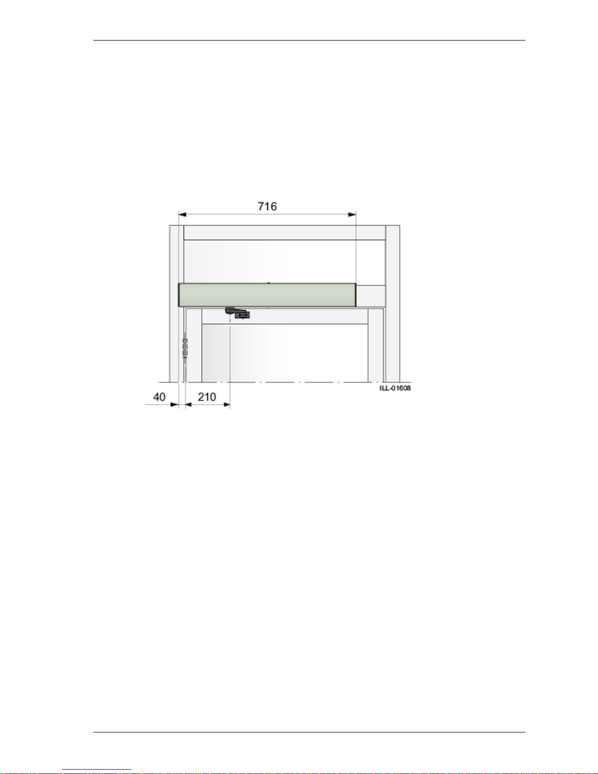
6.1 EM EMSW EMO, standard cover (wall mounted)
EM EMSW EMO is the standard operator. Pushing arm system shown. Measurement from hinge
centerline to outgoing shaft is always 210 mm regardless if butt or pivot hinged systems.
15Issue 2016-10-241005088-EMEI-16.0
6 Models
Page 16
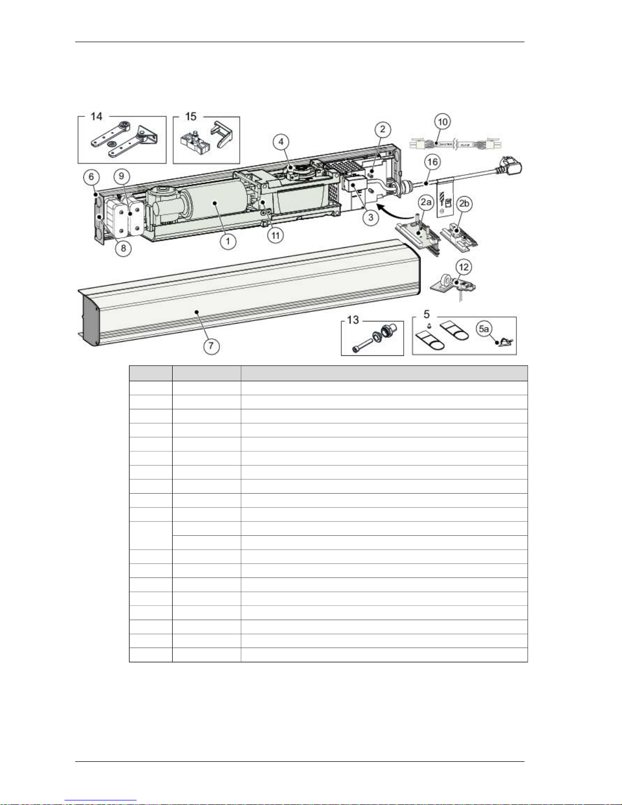
7 Part identification & Accessories
DescriptionArt. No.Item No.
Transmission unit3310034981
Control unit CU-ESD3310035322
EXU-SI (Kit to extend the security functions) - optional3310035542a
EXU-SA (Kit to extend the safety functions) - optional3310035572b
Mains contact3317006073
Door stop body3300002304
Mounting kit3310117975
Cable holder (50 pcs)3310035785a
Bottom end plate331003543BK/SI6
Cover3310049987
Power ON/OFF switch3310035818
ON/OFF/HOLD open switch - optional331003582
Battery backup unit - optional3310035679
Sync cable - optional33100358310
Encoder cable33000023311
MUL33100573612
Adaptor kit330000484BK/SI13
PUSH arm service kit330000485BK/SI14
PULL arm service kit330000486BK/SI15
Cable kit100634016
1005088-EMEI-16.0Issue 2016-10-2416
7 Part identification & Accessories
Page 17
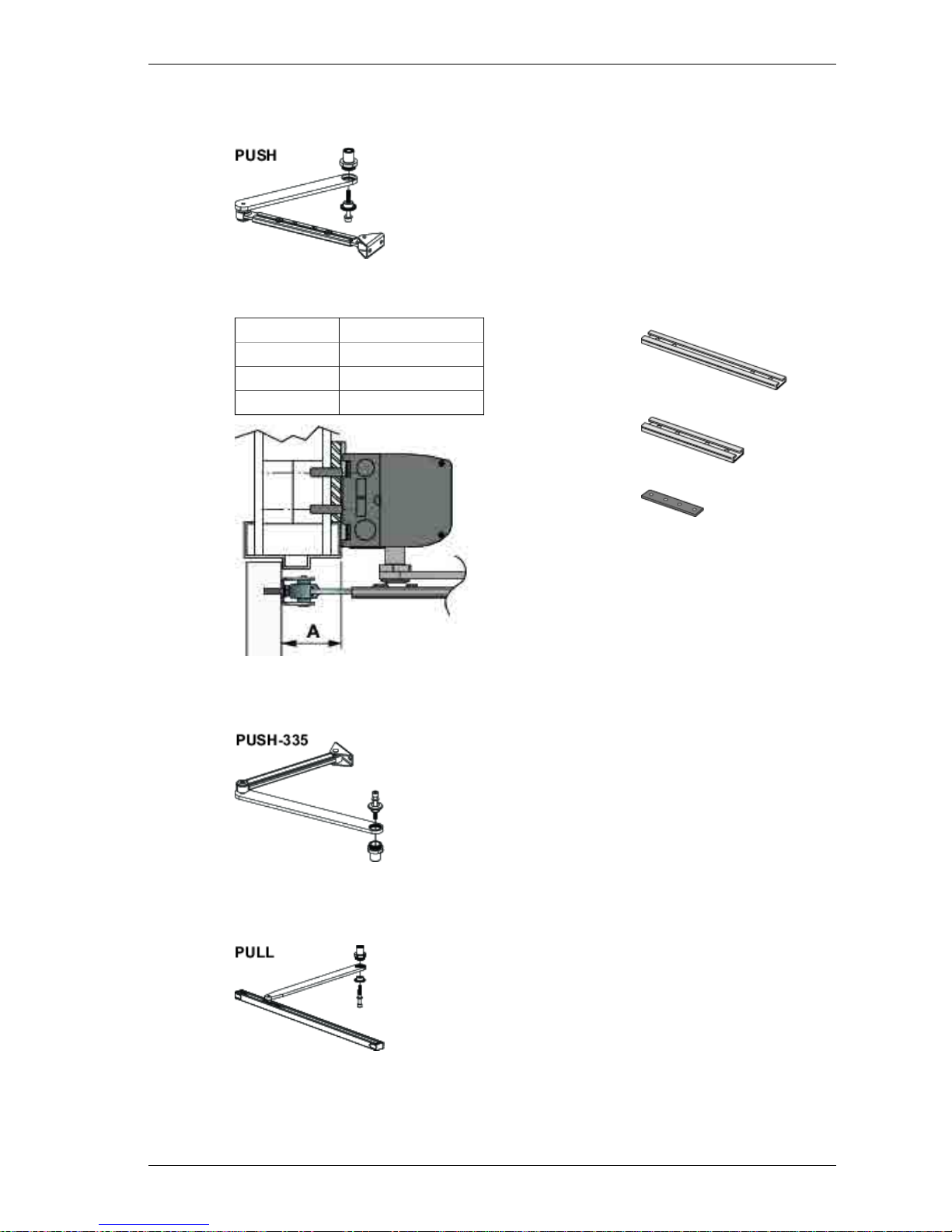
7.1 Arm system, PUSH
Art. No. 1014113BK/SI
It is used if the operator is installed on the wall on the opposite side of
the door swing and approved for fire applications.
7.1.1 PUSH-arm extensions
345 mm extension
Art. No. 173005BK/SI
ExtensionReveal = A
None (standard arm)0-100 mm
345 mm100-215 mm
230 mm + Joint part215-305 mm
230 mm extension
Art. No. 173004BK/SI
Joint part
Art. No. 173191
7.2 Arm system, PUSH-335
Art. No. 1011706BK/SI
It is used if the operator is installed on the door leaf hinge side.
7.3 Arm system, PULL
Art. No. 1011707BK/SI
It is used if the operator is installed on the wall on the same side as the
door swing.
17Issue 2016-10-241005088-EMEI-16.0
7 Part identification & Accessories
Page 18
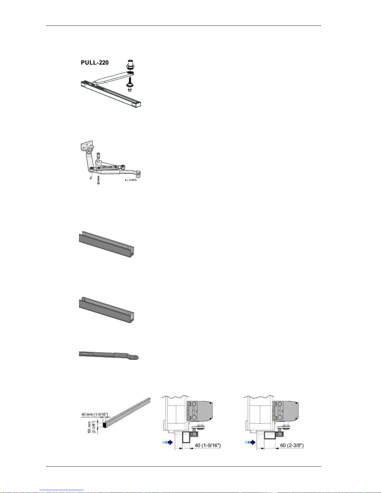
7.4 Arm system, PULL-220
Art. No. 1014114BK/SI
It is used if the operator is installed on the wall on the same side as the
door swing and when the door is 450-700 mm wide.
7.5 Arm system, ST-V / ST-H
ST-V, Art. No. 172312SI, 172313BK
ST-H, Art. No. 172314SI, 172315BK
Note! Door fitting not included.
It is used if the operator is installed on the wall on the same side
as the door swing and break-out unit is required.
7.5.1 Options for ST-V / ST-H
Door fitting standard
Art. No. 172071
Door fitting Break-out (pivot doors)
Art. No. 172325, right, reveal A = 0-60 mm or left when A > 60-100 mm
Art. No. 172327, right, reveal A > 60-100 mm or left when A = 0-60 mm
Arm extension
Art. No. 172320 required when the reveal A >60-100 mm
7.6 Reveal spacer: PULL / PULL-220
Art. No. PULL 1014667BK/SI
1005088-EMEI-16.0Issue 2016-10-2418
7 Part identification & Accessories
Page 19
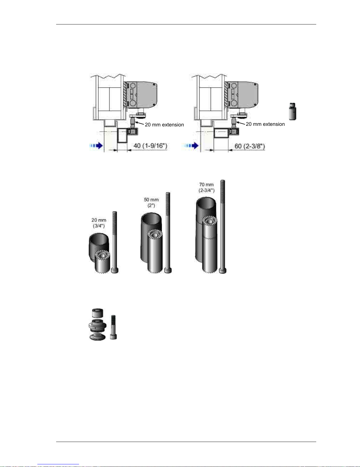
7.7 20 mm extension
Extension 20 mm for PULL/PAS and lower mounting of slide track profile.
Art. No.: 1011205
20 mm extension
20 mm extension
7.8 Drive shaft extension kits
Art. No.
173109BK/173109SI
Art. No.
173108BK/173108SI
Art. No.
173107BK/173107SI
Lower adapter M8, used for 20 mm lower installation height.
Art. No.
1007618
19Issue 2016-10-241005088-EMEI-16.0
7 Part identification & Accessories
Page 20

7.9 Control switches
7.9.1 Power ON/OFF switch
White
Brown
Art. No. 1003581
7.9.2 ON/OFF/HOLD open switch (will not operate electric lock)
White
Brown
Green
Art. No. 1003582
ProgramFunction
Impulses from activation units connected to XIMP are forwarded into inner impulse
(see page 50).
ON
Impulses from activation units connected to XIMP are not forwarded into inner impulse.
These units cannot open the door.
OFF
The door is held permanently open.HOLD
7.9.3 4-position switch PS-4C (operates the electric lock)
FunctionPosition
Art. No
655845
The door is closed. The door cannot be opened with inner and
outer activation units. The door is locked if an electromechanical
locking device has been fitted. The door can be opened with a key
switch (if fitted).
OFF
Passage from inside only. The door is normally locked if an electromechanical locking device has been fitted. The door can only
be opened with the inner activation unit and with a key switch (if
fitted).
EXIT
The door can be opened with the inner and outer manual and/or
automatic activators. The electric strike, if fitted, is open.
AUTO
Normal pos-
ition
The door is held permanently open by the motor.OPEN
1005088-EMEI-16.0Issue 2016-10-2420
7 Part identification & Accessories
Page 21
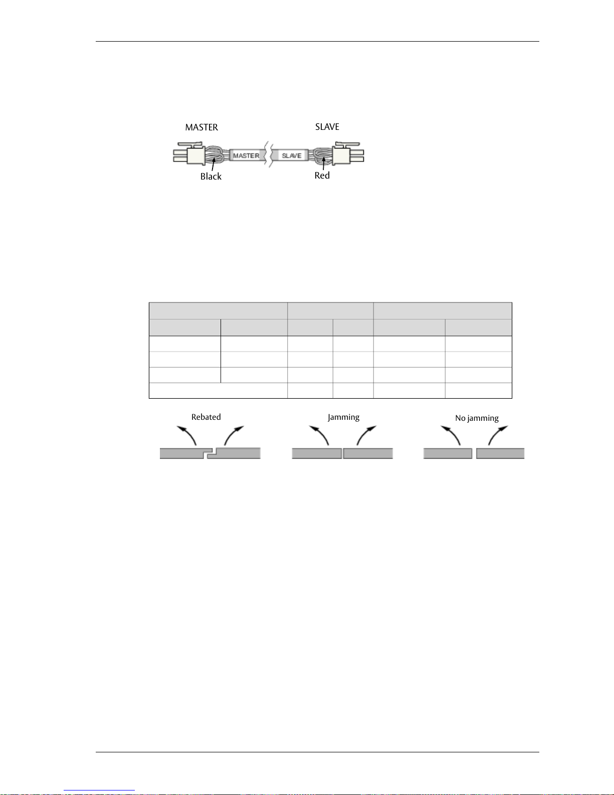
7.10 Sync cable for double doors (synchronizing of 2 operators)
Note! Connect a cable between Master CU and Slave CU.
Red
Black
SLAVE
MASTER
Note! The connection/marking of the sync cable determines which of the operators is the MASTER
and SLAVE.
For a Rebated door;
• the Master door must open before the Slave door
• the Slave door must close before the Master door
How to cut the jumper for double doors
Cut the jumper with colorDoor designFunction
SLAVE sideMASTER sideJammingRebatedClosingOpening
No cuttingNo cuttingNoNoSynchronousSynchronous
No cuttingCut blackNoYesAsynchronousSynchronous
Cut redNo cuttingYesYesAsynchronousAsynchronous
Cut redCut black——Double egress
Rebated
Jamming
No jamming
21Issue 2016-10-241005088-EMEI-16.0
7 Part identification & Accessories
Page 22

Settings for double doors
Settings on the
Function
SLAVEMASTER
Common
XProgram selection
XOpening time
XClosing time
XHold open time
XClose / Continue to open when the door is obstructed
XPAG On/Off
(X)*XLevel of Power assist
(X)*XExtended closing force
XOPD Impulse or Mat Logic Impulse
XSelection of operating mode during operation on battery
power
Individual
XXLock/Unlock signal voltage
XXLocked without/with power
XXLock release Enable/Disable
XXOpen Delay Time
XXLock kick Enable/Disable
* For “Double egress doors”, these functions must be set separately for MASTER and SLAVE as the
arm systems as well as the air pressure may be different.
Note!
• Locks on the MASTER and SLAVE doors must be connected to the control unit (CU) on the corresponding operator.
• Inner and outer impulses can be connected to either MASTER or SLAVE CU or both.
• The OPD is to be connected to the MASTER CU except for “Double egress”, where each OPD
must be connected to corresponding CU.
• Door leaf mounted sensors must always be connected to corresponding CU.
• The slave door can be prevented to open, if kill is activated on the SLAVE control unit.
1005088-EMEI-16.0Issue 2016-10-2422
7 Part identification & Accessories
Page 23
7.11 Extension units
For installation see page 51.
EXU-SA (kit for safety functions)
Art. No. 1003557
EXU-SI (kit for security functions)
Art. No. 1003554
AIU (Audible warning signal)
Art. No. 656083
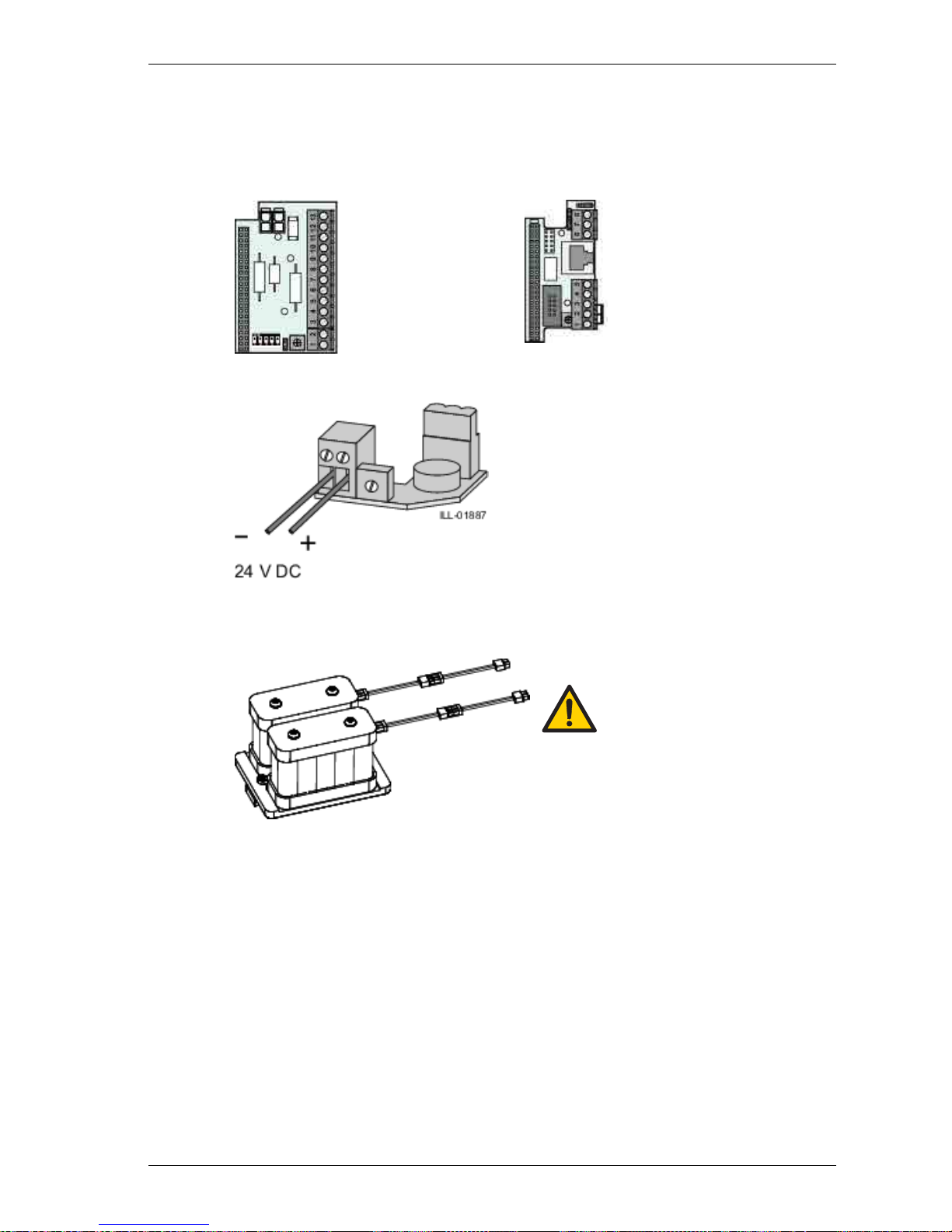
7.12 Battery backup unit
Note! Disconnectmains when replacing battery.
Risk of explosion if wrong type of battery is used.
Art. No. 1003567
23Issue 2016-10-241005088-EMEI-16.0
7 Part identification & Accessories
Page 24

7.13 Cover piece kit
7.13.1 Middle piece kit
Art. no 1008383
7.14 Labels
Label kit - including all below
Art. No. 1005227
Emergency break-out, DIN right door
Art. No. 1001785
Emergency break-out, DIN left door
Art. No. 1001786
Activation by disabled people
Art. No. 1003963
Operator designed for disabled people
Art. No. 1003964
Supervision of child
Art. No. 1001695
1005088-EMEI-16.0Issue 2016-10-2424
7 Part identification & Accessories
Page 25

8 Pre-installation
8.1 General tips/Safety concerns
In all instances, where work is being done, the area is to be secured from pedestrian traffic, and the power removed to prevent injury.
• If there are sharp edges after drilling the cable outlets, chamfer the edges to avoid damage to
the cables.
• For enhanced security and vandalism protection, always mount the operator access in the interior of a building whenever possible.
• Make sure the ambient temperature is in the range specified in section Technical specification.
• Make sure that the power is off before installing.
• Make sure that the door leaf and the wall are properly reinforced at the installation points.
• Unpack the operator and make sure that all parts are delivered in accordance with the packing
note and that the operator is in good mechanical condition.
• Ensure proper material is being used for the door leaves and that there are no sharp edges.
Projecting parts shall not create any potential hazards. If glass is used bare glass edges shall not
come in contact with other glass. Toughened or laminated glass are suitable glasses.
• Ensure that entrapment between the driven part and the surrounding fixed parts due to the
opening movement of the driven part is avoided. The following distances are considered sufficient
to avoid entrapments for the parts of the body identified;
- for fingers, a distance greater than 25 mm or less than 8 mm
- for heads, a distance greater than 200 mm
- for feet, a distance greater than 50 mm
- and for the whole body, a distance greater than 500 mm
• Danger points shall be safe guarded up to a height of 2.5 m from the floor level.
• The operator shall not be used with a doorset incorporating a wicket door.
8.2 Operator/Door handing
Operator/Door handing (DIN Right or DIN Left) is determined by which side the hinges are mounted
seen from the swing side.
DIN Left
DIN Right
25Issue 2016-10-241005088-EMEI-16.0
8 Pre-installation
Page 26

8.3 Installation examples
Non combustible
material in fire ap-
plication
Non combustible
material in fire
application
Steel reinforcement or rivnutA
Wood reinforcementB
Expansion-shell bolt (for brick wall min. M6x85,
UPAT PSEA B10/25)
C
Aluminium profile system1
Plasterboard wall2
Reinforced concrete wall and brick wall3
Plasterboard wall4
8.4 Fastening requirements (but not included)
Minimum requirements of wall profile*Base material
5 mm**Steel
6 mm**Aluminium
min. 50 mm from the undersideReinforced concrete
50 mmWood
Expansion-shell bolt, min. M6x85, UPAT PSEA B10/25, min. 50 mm from
the underside
Brick wall
* Entrematic Nordic minimum recommended requirements. Building Codes may give different
specifications.
** Thinner wall profiles must be reinforced with rivnuts.
1005088-EMEI-16.0Issue 2016-10-2426
8 Pre-installation
Page 27

8.5 Tools required
• Torx T10
• Metric Allen wrenches 2,5; 3; 4 and 6 mm
• Flatblade screwdriver (potentiometer and terminal size)
• Screwdriver (Philips size 2)
• Nut driver, 5 mm
• Carpenter’s level
• Tape rule
• Power drill and set of drill bits
• Center punch
• Wire stripper
• Silicone sealant
• Installation and Service Manual (this manual)
8.6 Installation on double doors
If the operators are to be mounted at the same height with pushing and pulling arm systems, the
height is determined by the pulling arm system, PULL. The pushing arm system PUSH must always
have a shaft extension, minimum 50 mm, maximum 70 mm to match the mounting heights visually.
Example: if PULL has a 20 mm extension, the PUSH must have a 70 mm extension. If PULL has 0 mm
extension, the PUSH must have a 50 mm extension.
27Issue 2016-10-241005088-EMEI-16.0
8 Pre-installation
Page 28

9 Mechanical installation
Note! Consider all power wire entry locations and signaling wires before preparing back plate.
9.1 Operator with PUSH arm system
0 - 100 (305)
1005088-EMEI-16.0Issue 2016-10-2428
9 Mechanical installation
Page 29

Cont. "Operator with PUSH arm system"
DIN Right
Cable inlet
29Issue 2016-10-241005088-EMEI-16.0
9 Mechanical installation
Page 30

Cont."Operator with PUSH arm system"
Operator should be attached using the
top/centered bolt first, then follow pattern
1005088-EMEI-16.0Issue 2016-10-2430
9 Mechanical installation
Page 31

Cont."Operator with PUSH arm system"
DIN Left
31Issue 2016-10-241005088-EMEI-16.0
9 Mechanical installation
Page 32

Cont."Operator with PUSH arm system"
Operator should be attached using
the top/centered bolt first, then fol-
low pattern
1005088-EMEI-16.0Issue 2016-10-2432
9 Mechanical installation
Page 33

Cont."Operator with PUSH arm system"
33Issue 2016-10-241005088-EMEI-16.0
9 Mechanical installation
Page 34

9.2 Operator with PULL arm system
Note! Measurement Z must be reduced by 20 mm if lower adapter from
kit 1007618 is used.
1005088-EMEI-16.0Issue 2016-10-2434
9 Mechanical installation
Page 35

Cont. "Operator with PULL arm system"
DIN Left
35Issue 2016-10-241005088-EMEI-16.0
9 Mechanical installation
Page 36

Cont. "Operator with PULL arm system"
Operator should be attached using
the top/centered bolt first, then follow
pattern
1005088-EMEI-16.0Issue 2016-10-2436
9 Mechanical installation
Page 37

Cont. "Operator with PULL arm system"
DIN Right
37Issue 2016-10-241005088-EMEI-16.0
9 Mechanical installation
Page 38

Cont. "Operator with PULL arm system"
Operator should be attached using
the top/centered bolt first, then follow
pattern
1005088-EMEI-16.0Issue 2016-10-2438
9 Mechanical installation
Page 39

Cont. "Operator with PULL arm system"
DIN Right
DIN Left
39Issue 2016-10-241005088-EMEI-16.0
9 Mechanical installation
Page 40

9.3 Installation of operator with arm system ST
1005088-EMEI-16.0Issue 2016-10-2440
9 Mechanical installation
Page 41

Cont. "Installation of operator with arm system ST"
Outside open door
DIN Left
41Issue 2016-10-241005088-EMEI-16.0
9 Mechanical installation
Page 42

Cont. "Installation of operator with arm system ST"
Operator should be attached
using the top/centered bolt
first, then follow pattern
Operator should be attached using
the top/centered bolt first, then fol-
low pattern
1005088-EMEI-16.0Issue 2016-10-2442
9 Mechanical installation
Page 43

Cont. "Installation of operator with arm system ST"
Outside open door
DIN Right
43Issue 2016-10-241005088-EMEI-16.0
9 Mechanical installation
Page 44

Cont. "Installation of operator with arm system ST"
Operator should be attached us-
ing the top/centered bolt first, then
follow pattern
1005088-EMEI-16.0Issue 2016-10-2444
9 Mechanical installation
Page 45

Cont. "Installation of operator with arm system ST"
Note, the way of mounting the arm!
45Issue 2016-10-241005088-EMEI-16.0
9 Mechanical installation
Page 46

Cont. "Installation of operator with arm system ST"
1005088-EMEI-16.0Issue 2016-10-2446
9 Mechanical installation
Page 47

Cont. "Installation of operator with arm system ST"
47Issue 2016-10-241005088-EMEI-16.0
9 Mechanical installation
Page 48

Cont. "Installation of operator with arm system ST"
Cut out for arm bracket
DIN Right
DIN Left
1005088-EMEI-16.0Issue 2016-10-2448
9 Mechanical installation
Page 49

10 Electrical connection
Note! During any work with the electrical connections the mains must be disconnected.
• Place the electric switch easily accessible from the operator. If a plug contact is used in the installation the wall socket shall be placed easily accessible from the operator.
• If the supply cord is damaged, it must be replaced by the manufacturer, its service agent or
similarly qualified persons in order to avoid a hazard.
10.1 Mains connection
a Switch off the mains.
b Assemble the bottom end plates and tighten the two screws firmly.
c Connect the plug contact to the wall socket or connect to the mains switch.
Note! The mains switch must be connected according to national regulation.
d Connect the mains to the operator.
Mains:100-240 V AC – 50/60 Hz
Alt. 1
Mains
Alt. 2
Symbol shown to ensure that the manual is read before the installation starts.
PE = Yellow/Green
L = Brown
N = Blue
Mains
49Issue 2016-10-241005088-EMEI-16.0
10 Electrical connection
Page 50

10.2 Control units
10.2.1 CU-ESD
The CU-ESD can be equipped with extension units, EXU-SI and/or EXU-SA, depending on the functions
required. See page 12 or 13.
Power ON/OFF switch
Encoder
Motor
Synchronizing of double doors
ON/OFF/HOLD open switch
Lock-out for OPD (–)
Overhead presence detection/Mat safety
Inner impulse
Ground
Overhead presence detection (incl. 24 V, LOUT and
Safety Impulse)
= ERROR
Hold open time
DIP-switches shown in
OFF position
Closing torque
Power assist
Closing speed
Opening speed
Spring tension
PAG
MAT
SOS
PUSH & GO
Safety mat
Stop on stall
ARM 1/2 Arm system setting
LEARN BUTTON
Inner impulse controlled by
10.2.2 Arm system selection
Factory set arm configuration is PUSH, if PULL or ST is required:
a Switch power OFF
b Select arm configuration
c Switch power ON
1005088-EMEI-16.0Issue 2016-10-2450
10 Electrical connection
Page 51

10.2.3 Extension units EXU-SI / EXU-SA
Installation
To extend the functions, the extension units can be mounted on top of the control unit CU-ESD,
separately or combined.
5 mm nut driver
Torx T10
Mains
Tag strip
long 2 pcs EXU
short 1 pc EXU
51Issue 2016-10-241005088-EMEI-16.0
10 Electrical connection
Page 52

10.2.4 Extension unit EXU-SI
Functions
This extension unit has inputs for electro-mechanical lock, program selector, batteries, KILL function, OPEN/CLOSE,
KEY opening and outer impulse.
Program selector
Unlocked signal from lock
KILL reset (see jumper below)
KILL impulse
KEY impluse (5 s)
OPEN / CLOSE impulse (latching relay)
Outer Impulse
Ground
Electro-mechanical locking device (12V DC max. 500 mA /
24 V DC max 250 mA, see DIP-switch No. 1 below)
Potentiometer for opening delay
2)
Manual kill reset (jumper off)
Automatic kill reset (jumper on)
Battery monitoring
Lock kick
1)
Lock release
2)
Locked without power (OFF) / with power (ON)
Lock 12 V (OFF) / 24 V (ON)
DIP-switches
shown in OFF
position
Battery backup unit
Position OFF: Smooth closing, to be used on doors without lock.
Position ON: More powerful closing, to be used on doors with lock, to overcome binding in the locking device.
1)
If the switch is set to ON, the LOCK RELEASE is active during the opening delay time set by the potentiometer.
For PAIR OF DOORS installations, the LOCK RELEASE works in sequence: First the MASTER then the SLAVE.
2)
Note! Lock only functions when Program Selector is in OFF or EXIT.
1005088-EMEI-16.0Issue 2016-10-2452
10 Electrical connection
Page 53

10.2.5 Extension unit EXU-SA
This extension unit has inputs for door mounted sensors, which can give presence impulse on approach side
and/or presence detection on swing path side. Relay output for error indication, KILL output, Lock output or
door indication is also integrated. When the jumper for the relay is set to ‘Open/Closed door indication’, its activation will follow the Blanking LED.
Functions
Monitoring of presence detection/DMPS.SS
Monitoring of presence impulse/DMPS.NS
No monitoring (both jumpers on)
Monitoring of presence detection and presence impulse
External error indication
Opened door indication
Relay output (“External error indication” or“Open
door indication”, see above) 24 V, 1 A
Ground
Remove strapping when connecting to terminals 2
and/or 3
Blanking potentiometer
(Adjust the potentiometer to avoid presence detection sensor to detect
the wall. Range 45 - 90 degrees.)
Blanking LED
Door mounted sensors
2)
DMPS:
Relay 1: Presence impulse (NC)
Relay 2: Presence detection (NC)
(-) 0 VDC Ground
(+) 24 VDC
QTST = Sensor monitoring
PDET = Presence detection (NC)
1)
PIMP = Presence impulse (NC)
1)
1)
If not used strap to “Ground”.
2)
Remove strapping from terminals 2 and/or 3.
53Issue 2016-10-241005088-EMEI-16.0
10 Electrical connection
Page 54

10.3 Sensor cable inlet
Art. No.: 1007567
Alt. 1
Alt. 2
Art. No.: 1015369BK/SI
1005088-EMEI-16.0Issue 2016-10-2454
10 Electrical connection
Page 55

11 Start-up
The spring pre-tension is factory set to 210° and is normally not necessary to adjust. If adjustment
has to be carried out, see page 68.
11.1 Adjusting the door stop
a Close the door.
b Turn the potentiometer SPTE to 0° (if not already on 0°).
c Switch on the mains (the operator will find its closed position).
d Open the door to required open position, plus approx. 5/8” (15 mm), by turning the poten-
tiometer SPTE on the CU-ESD, clockwise.
55Issue 2016-10-241005088-EMEI-16.0
11 Start-up
Page 56

e Loosen the door stop arm.
f Mount the door stop arm on the splines a), as close as possible to the stop block b). Fine-adjust
if necessary with the screw on the stop block c).
g Close the door by turning the potentiometer SPTE to 0° and let the door close.
Note! Impulses are not accepted if SPTE is more than 0°.
Door stop arm1
Fixing screw2
Stop block3
Fine-adjustment screw4
1005088-EMEI-16.0Issue 2016-10-2456
11 Start-up
Page 57

11.2 Auto-learn – automatically sets back and latch check (recommended)
This learning is performed by pushing the LEARN BUTTON (LRN).
• Before the learning procedure starts, make sure that the door has been properly closed i.e., not
by force.
• If any of the parameters SPRING PRE-TENSION, CLOSING TORQUE (CLTQ) and LOCK RELEASE
(DIP-switch No. 3 on EXU-SI) are changed after performing a learn, a new learn must be carried
out.
• Learn can be carried out with activation units and locks connected.
• The back-check will be automatically adjusted to 10° and 1 second before open position. The
latch-check will be automatically adjusted to 10° and 1.5 seconds before closed position.
Back-check
Latch-check
11.2.1 One push / two pushes on the LEARN BUTTON (LRN)
Note! Remain clear of swing path of door, as door may close rapidly. The door has no safety during
auto-learn cycle.
One push (delayed opening)
Push the button once. The door will open after 2 seconds and adjust the back-check and latchcheck automatically.
Two pushes (direct opening)
Push the button twice. As above, but the door starts to move directly.
11.2.2 Double doors
For double doors, the MASTER door must be learned first and thereafter the SLAVE door. When the
SLAVE door is learned, the MASTER door will open up to fully open position during the learning
phase of the SLAVE door.
The doors can also be learned separately before connecting the sync cable. In case of astragal doors
and separate learning, the MASTER door must be held open before the SLAVEdoor learn is carried
out.
57Issue 2016-10-241005088-EMEI-16.0
11 Start-up
Page 58

11.3 General adjustment
a Set the hold open time with the potentiometer on the control unit.
b Adjust the opening speed (OPSP). Turning clockwise increases the speed.
c Adjust the closing speed (CLSP). Turning counter-clockwise decreases the speed.
d Connect the required activation units.
e Check that the installation complies with Installation and adjustments on page 69.
1005088-EMEI-16.0Issue 2016-10-2458
11 Start-up
Page 59

11.4 Connection of activation units and accessories
See sensor manuals for mounting and adjustments. Protective device shall comply with EN 12978.
Door mounted
When sensors are used in order to avoid contact with the door leaf it is required that the presence
detect sensor and the presence impulse sensor fulfills Performance Level = d according to EN ISO
13849-1. These sensors shall also be monitored (tested) by EM EMSW EMO door operator.
Configue sensor EMSP33-M:
DIP A7 to ON (for Master sensor)
DIP B4 to ON for Presence impulse
DIP B4 to OFF for presence detection
** Note! When using the quick connector, opening
and closing side will be reversed.
PS-4C
Eye-Tech
Activation
sensor
BrownAInner impulse
YellowBOuter Impulse
PinkCKey Impulse
VioletDPresence impulse
WhiteEPresence detection
BlueFOff
RedGKill impulse NO
GreenHStandard*
BlackI
59Issue 2016-10-241005088-EMEI-16.0
11 Start-up
Page 60

12 Cover
The cover and back plate are manufactured in clear anodized aluminium. The end plates are made
of black painted steel sheet.
12.1 Fitting and removing the cover
The cover is slid over flanges in the back plate so that the ridges fit in the grooves.
Break off and snap on the fill cover into the back plate for output shaft. Snap on the other fill cover
for the second slot. Secure cover with the screw.
When properly installed and adjusted, attach the product label, which includes the CE mark on the
right side of the lower part of the operator cover (see illustration).
Apply the EM logotype to the cover – see illustration.
Only for SE: Apply the SITAC label next to the product label - see illustration.
Disconnect from
supply before
servicing
1005088-EMEI-16.0Issue 2016-10-2460
12 Cover
Page 61

12.2 Middle piece cover
61Issue 2016-10-241005088-EMEI-16.0
12 Cover
Page 62

13 Signage
Check that all required signage is applied and intact. Mandatory indicates that the signage is required
by European directives and equivalent national legislation outside the European Union.
Product label: Mandatory
Emergency break-out: Mandatory, if approved for escape route.
Entrematic Nordic door sticker: Mandatory, if applicable to highlight the presence of the glass (applied to all glass sections
that are moving).
Supervision of child: Mandatory, if applicable (applied to both sides of the door). To be placed on entrances where the risk
analysis shows use by children, elderly and disabled.
Operator designed for disabled people:
Recommended, if applicable (applied to both sides of the door).
Activation by disabled people: Recommended, if applicable.
SITAC label: Mandatory in SE
No entry, identifying one-way traffic: Mandatory in GB and US, if applicable, not included in the product.
1005088-EMEI-16.0Issue 2016-10-2462
13 Signage
Page 63

14 Advanced settings
14.1 Learn with advanced setting of “back- and latch-check”
See the prerequisites for performing a “learn” under the heading Auto-learn – automatically sets
back and latch check (recommended) on page 57.
a Push the button once or twice as for auto-setting.
b Stop the door at required back-check.
c The door reverts towards closed position.
d Remove the stop.
e Stop the door at required latch-check.
f The door reverts to learn the fully open position.
g Remove the stop.
h The door reverts to closed position.
14.2 Revert to default values for “back- and latch-check" (Level 1)
a Disconnect batteries if any.
b Disconnect the mains.
c Press the LEARN BUTTON (LRN) and keep it depressed.
d Connect the mains.
e Watch the ERROR LED.
f Release the LEARN BUTTON after 1 flash (LED is out).
g The BACK CHECK, LATCH CHECK and OPEN POSITION have now reverted to default values.
h Disconnect the mains.
i Next time the mains is connected, a new learn is needed to be run, and the operator will use
the default values.
63Issue 2016-10-241005088-EMEI-16.0
14 Advanced settings
Page 64

14.3 Changing group of parameters (Level 2)
a Disconnect batteries if any.
b Disconnect the mains.
c Press the LEARN BUTTON (LRN) and keep it depressed.
d Connect the mains.
e Watch the ERROR LED.
f Release the LEARN BUTTON after 2 flashes (LED is out).
The ERROR LED flashes a number of short flashes that corresponds to the parameter group
number (see table). After a short pause the LED will repeat the group number, and so on.
g Pushing the LEARN BUTTON once, increases the parameter group number. When the highest
parameter group number is reached it will start with number 1 (default) again.
h Pushthe button until you get the requested parameter group. Ensure that the requested group
of parameters has been selected by counting the number of flashes.
i Disconnect the mains.
j Next time the mains is connected, the operator will use the new group of parameters.
10987654321 (default)Parameter/ Group
15 minutes15 minutes15 minutes15 minutes15minutes15 minutes15 minutes15 minutesInfinite15 minutesOPEN/CLOSE
HOLD OPENTIME
ConveniencePower SavePower SavePower SavePower SavePower SavePower SaveConveniencePower SavePower SaveBATTERY mode
Locked during KILL
Lock follows
program selector during
KILL
Locked during KILL
Locked during KILL
Locked during KILL
Locked during KILL
Lock follows
program selector during
KILL
Locked during
KILL
Locked during KILL
Locked during KILL
KILL mode
Reverses
when obstructed
Door closerDoor closerDoor closerDoor closerReverses
when obstructed
Door closerDoor closerDoor closerDoor closerOBSTRUCTION
mode
1)
Separate
presence detection
Separate pres-
ence detec-
tion
Separate
presence detection
Separate
presence detection
Common
presence detection
Separate
presence detection
Separate
presence detection
Separate presence detection
Separate
presence detection
Separate
presence detection
DOUBLE EGRESS
mode
OnOnOnOffOnOnOnOnOnOnLOCK RETRY
In AUTO
mode
In AUTO
mode
In OFF, EXIT
and AUTO
mode
In AUTO
mode
In AUTO
mode
In AUTO
mode
In AUTO
mode
In AUTO
mode
In AUTO
mode
In AUTO
mode
OPEN/CLOSE impulse
Normally
Open
Normally
Closed
Normally
Open
Normally
Open
Normally
Open
Normally
Open
Normally
Open
Normally
Open
Normally
Open
Normally
Open
KILL Impulse
Configuration
1)
If set to REVERSES WHEN OBSTRUCTED, the operator re-opens when obstructed, similar to a presence impulse.
As default the operator tries to close two times extra in automatic operation, OFF or EXIT mode and one time in manual operation, OFF or
EXIT mode if there is a problem with binding striking plates. This function can be switched off (see LOCK RETRY above).
Note! When changing group of parameters, normally only the master control must be configured in a double door application. When
changing from or to group seven, both MASTER and SLAVE must be configured.
1005088-EMEI-16.0Issue 2016-10-2464
14 Advanced settings
Page 65

14.4 Classification (Level 3)
a Disconnect batteries if any.
b Disconnect the mains.
c Press the LEARN BUTTON (LRN) and keep it depressed.
d Connect the mains.
e Watch the ERROR LED.
f Release the LEARN BUTTON after 3 flashes (LED is out).
g Identify the current classification
The ERROR LED flashes an amount of short flashes that correspond to the classification number.
After a short pause the LED will repeat the classification number and so on.
h Changing the classification
If you push the LEARN BUTTON once, the classification number will increase. When you have
reached the highest classification number it will start at number one again.
• Push the button until you get the requested classification
• Disconnect the mains
Next time the mains is connected, the operator will use the new classification.
i Classification table
21Classification
Low energyFull power(Default)
EN 16005Standard
Automatic limitation 1.69 J3 - 6 sOpening speed
Automatic limitation 1.69 J3 - 6 sClosing speed
The fastest setting of Opening Speed and Closing Speed are automatically limited to the value
in the table, and can only be reduced.
If classification 2, Low energy,is used the operator will automatically follow the speed limitation
in EN 16005.
The learn procedure must be carried out after a change of the classification setting.
Speed settings for Low energy mode
The table shows minimum opening time to back check or to 80° open or minimum closing
time from 90° to 10° open.
Door mass (kg)Width of door leaf (mm)
9080706050
Time (s) min
3,53,33,23,23,0750
3,63,43,23,13,1850
4,24,03,73,43,21000
5,14,84,54,23,81200
65Issue 2016-10-241005088-EMEI-16.0
14 Advanced settings
Page 66

14.5 Overhead Presence Detection (OPD) Monitoring (Level 4)
a Disconnect batteries if any.
b Disconnect the mains.
c Press the LEARN BUTTON (LRN) and keep it depressed.
d Connect the mains.
e Watch the ERROR LED.
f Release the LEARN BUTTON after 4 flashes (LED is out).
g Identify the current monitoring
The ERROR LED flashes an amount of short flashes that correspond to the status number.
After a short pause the LED will repeat the status number and so on.
h Changing the status
If you push the LEARN BUTTON once, the status number will increase. When you have reached
the highest status number it will start at number one again.
• Push the button until you get the requested monitoring status, 1 = OFF (default), 2 = ON
• Disconnect the mains
Next time you connect the mains the operator will use the new status setting.
i Recommended settings for sensor SP34-M
Sensor dip switch settings
Dip 1 = ON
Dip 2-8 = OFF
Interface dip switch settings
Dip 1, 4 and 7 = OFF
Dip 2, 3, 5, 6 and 8 = ON
1005088-EMEI-16.0Issue 2016-10-2466
14 Advanced settings
Page 67

14.6 Lock kick (Level 5)
a Disconnect batteries if any.
b Disconnect the mains.
c Press the LEARN BUTTON (LRN) and keep it depressed.
d Connect the mains.
e Watch the ERROR LED.
f Release the LEARN BUTTON after 5 flashes (LED is out).
g Identify the current lock kick status
The ERROR LED flashes an amount of short flashes that correspond to the status number.
After a short pause the LED will repeat the status number and so on.
h Changing the status
If you push the LEARN BUTTON once, the status number will increase. When you have reached
the highest status number it will start at number one again.
• Push the button until you get the requested lock kick status, 1 = Basic (default), 2 = Enhanced
• Disconnect the mains
Next time the mains is connected, the operator will use the new status setting.
14.7 Lock unlocked status (Level 6)
a Disconnect batteries if any.
b Disconnect the mains.
c Press the LEARN BUTTON (LRN) and keep it depressed.
d Connect the mains.
e Watch the ERROR LED.
f Release the LEARN BUTTON after 6 flashes (LED is out).
g Identify the current lock unlocked status
The ERROR LED flashes an amount of short flashes that correspond to the status number.
After a short pause the LED will repeat the status number and so on.
h Changing the status
If you push the LEARN BUTTON once, the status number will increase. When you have reached
the highest status number it will start at number one again.
• Push the button until you get the requested status, Lock is unlocked at
1= Lock is unlocked when door is not closed
2= Lock is unlocked when door is 0-10 degrees from closed position, during opening
• Disconnect the mains
Next time the mains is connected, the operator will use the new status setting.
67Issue 2016-10-241005088-EMEI-16.0
14 Advanced settings
Page 68

15 Reducing / Increasing the “Spring pre-tension” (SPTE)
The spring pre-tension is factory set to 210° and is normally not necessary to adjust. If adjustment
has to be carried out see below.
a Loosen the door stop arm. Remove if fitted on the topside, slide down if fitted on the bottom.
b Turn the potentiometer for spring pre-tension (SPTE) clockwise until the door opens to 45°.
c Loosen the drive arm fixing screw.
d Moving the door towards open position, reduces the tension, or:
Moving the door towards closed position, increases the tension.
e Tighten the drive arm.
f Turn the potentiometer SPTE to 0°.
g Open the door to required open position, plus approx. 15 mm, by turning the potentiometer
SPTE clockwise.
h Mount the door stop arm as close as possible to the open door stop block, fine- adjust with the
screw if necessary.
i Turn the potentiometer SPTE to 0°.
j Push the LEARN BUTTON.
k Let the door do the learn cycle without touching it.
Note! Max. allowable spring pre-tension is 210°. Over-tension may damage the spring or overheat
the motor.
1005088-EMEI-16.0Issue 2016-10-2468
15 Reducing / Increasing the “Spring pre-tension” (SPTE)
Page 69

16 Installation and adjustments
16.1 Complementary Safety Devices Swing Doors
If there is any risk for finger jam, add finger protection strip at the hinge side for internal doors,
article No. 833334 or add finger protection roll for external doors, article No. 833333.
16.2 Swing Doors Opening and Closing Time
Adjust, as a minimum, the operator's opening and closing time according to the diagram below.
16.2.1 How to find the correct opening and closing time
• Measure the door width.
• If the door weight is unknown, follow the instructions in “Diagrams for door weight”.
• Go into the diagram below to find the correct minimum opening/closing time “t”.
Example: If the door width is 1,1 m and the door weight is 50 kg the minimum opening and closing
time will be ~3,5 seconds.
Minimum Swing Door Opening/Closing Time, t for LE
Compliance [s]
Door Width in metres
Example
Door Weight
69Issue 2016-10-241005088-EMEI-16.0
16 Installation and adjustments
Page 70

16.3 Diagrams for Door weight
a Measure the door width (DW) and the door height (DH) in metres for one door leaf only.
b Calculate the area DW x DH.
c Select diagram for your type of door and the actual glass thickness. Find the weight.
Example: Aluminium door with measurement DW = 1.5 m, DH = 2 m and glass thickness 12 mm.
Calculate 1.5 x 2 = 3 m2. Look into the first diagram for “Aluminium Frame with glass”. Start with
the area and follow the line up to the 12 mm glass, go left to receive the door weight 95 kg.
Note! The weights can vary depending on the door design (the table shows only typical values).
16.3.1 Aluminium frame with glass
Door leaf weight [kg]
Door leaf area [m2]
Example
8/24/8 glass
12 mm glass
6/10/6 glass
10 mm glass
8 mm glass
6 mm glass
1005088-EMEI-16.0Issue 2016-10-2470
16 Installation and adjustments
Page 71

17 Troubleshooting
Remedies/ExplanationsPossible reasons whyFault
Change the setting of the control switchControl switch is set to OFFThe door does not open
The motor does not start
Check the mains switchMains are missing
Strap impulse inputsActivation unit does not function
Check that there are no objects in the detection zone
Presence detection is activated
Deactivate KILLKILL activated
Turn SPTE to 0°Potentiometer SPTE not turned
to 0°
Unlock the lockMechanical lock is lockedThe motor starts
Remove objectSomethingjammed beneath the
door
Select lock releaseElectric striking plate is binding
Adjust striking
Turn potentiometer SPTE until the door-stop
hits the stop-block. Put the door in required
open position. Tighten the arm system. Turn
SPTE to 0°
Arm system has come loose
Change the setting of the control switchControl switch is set to HOLDThe door does not close
Remove objects in the detection zonePresence impulse is activated
Remove objectSomethingjammed beneath the
door
a Turn up the potentiometer SPTE until it is
possible to loosen the door stop
b Removethe door stop and the arm system
c Unplug the mains and let spring close
d Unplug the motor plug
e Mount the drive arm from the arm system
and find the o-pre-tension by moving back
and forth
f Loosen the arm
g Connect the motor plug
h Connect the mains
i Turn the SPTE pot to 210° and wait until
the spindle stops turning
j Mount the door stop against the closing
stop block
k Turn down SPTE to 0º - operator is now
factory set
l Turn to section 11 to adjust open stop po-
sition
Too many adjustments carried
out
The operator has unknown spring pre-tension
71Issue 2016-10-241005088-EMEI-16.0
17 Troubleshooting
Page 72

17.1 Error indication
• During normal operation the ERROR LED on the control unit is illuminated.
• An extinguished LED indicates that there is no mains.
• A flashing light on the LED indicates that the operator is out of function (see table below).
• An audible warning signal can be achieved by using the accessory board AIU. It is connected to
the 24 VDC and plugged into the EXU-SA relay output terminal.
RemedyReasonLED flash frequency
Check for short circuit or broken monitored
sensor
+ 24 V DC external error or
sensor monitoring error
One 0.3 s flash, pause etc.
Replace battery (normal operation with mains)Battery defectiveTwo 0.3 s flashes, pause etc.
Replace control unitControl unit defectiveThree 0.3 s flashes, pause etc.
Check the encoder cable.
Open and close the door manually and thereafter
check the automatic function. If the operator is
still out of function replace the drive unit.
Encoder errorFour 0.3 s flashes, pause etc.
Check for e.g. short circuit in the locking deviceLocking device defectiveFive 0.3 s flashes, pause etc.
Replace locking device
Replace EXU-SI boardEXU-SI board defective
Connect the sync cableSync cable not connected or
defective (double door only)
Six 0.3 s flashes, pause etc.
Replace the sync cable
Check the flash frequency on the SLAVE LED and
take necessary measures in accordance with this
table.
SLAVE control unit defective
(double door only)
Seven 0.3 s flashes, pause etc.
Wait for the motor to cool downMotor overheatedEight 0.3 s flashes, pause etc.
Toggle impulseBlocked door and constant
impulse
Nine 0.3 s flashes, pause etc.
1005088-EMEI-16.0Issue 2016-10-2472
17 Troubleshooting
Page 73

18 Service / Maintenance
Regular inspections shall be made according to national regulations and product documentation
by an Entrematic Nordic-trained and qualified technician. The number of service occasions should
be in accordance with national requirements and product documentation. This is especially important when the installation concerns a fire-approved door or a door with an emergency opening
function.
As with all other technical products, an automatic door needs maintenance and service. It is essential
to know the importance of maintenance to have a reliable and safe product.
Service and adjustments will ensure a safe and proper operation of an automatic door unit.
The “Service Log Book” shall be used together with the “Site Acceptance Testand Risk Assessment”
document provided. Keep both documents available for maintenance and service records.
The table below shows the recommended interval in months, when to replace parts during preventive maintenance.
Abusive
Environment
Cycles/hour in operation
Part numberPart
>100<100<10
High
traffic
Medium
traffic
Low
traffic
661224331003498Transmission unit
661224330000485BK/SIPUSH/PUSH-335 service kit
661224330000486BK/SIPULL/PULL-220 service kit
661224330000484BK/SIAdaptor kit
661224331003540Door stop body
661224331003887ST-V/H service kit
24242424331003567Battery backup unit *
60606060331003532CU-ESD control unit
Disconnect mains when replacing battery.*
Risk of battery explosion if wrong type of battery is used. If Battery Monitoring DIP is ON, then
a reset of this is needed (after changed batteries), see section 5.4.6.
73Issue 2016-10-241005088-EMEI-16.0
18 Service / Maintenance
Page 74

Entrematic Nordic AB, Lodjursgatan 10, SE-261 44 Landskrona, Sweden
Tel: +46 10 47 48 300
www.entrematic.com • info.em@entrematic.com
 Loading...