

Page 1

Swing Door Operator
EM EMSW
701500
HSO
HSO
LSO
LSO
LSCLK
HSC
HSC
LSC
701448
LK
12 3 4
TB2
TB2
0 V DC
24 V DC
0 V DC
Kill
Key Impulse
Lock 24 V DC
Kill jumper
MVI N.O. / N.C.
MVI Open Lock / Door
Lock w. / w.o. power
Lock time 1.5 s / until closing
Slave delay off / on
Master / Slave
Push & Go
Outer Impulse
MVI Impulse
1003870
ALL TB1 AND TB2,
CLASS 2 SUPPLY
MAX. 24 V
0 V DC
24 V DC
Motor control
"Slave"
ON
123
4
5678
H.O.T
Opening Delay
MVI H.O.T
1
2
3
4
S
W
5
6
7
8
9
10
11
13
12
14
Installation and Service Manual
Original instructions
1004291-EMEI-10.0 – Issue 2016-01-27
Page 2

© All rights in and to this material are the sole property of Entrematic Group AB. Copying, scanning, alterations or modifications are
expressly forbidden without the prior written consent of Entrematic Group AB. Rights reserved for changes without prior notice.
Backtrack information: folder:Workspace Main, version:a289, Date:2016-01-27 time:06:49:12, state: Frozen
Page 3

CONTENTS - Original instructions
51 Revision .....................................................................................................................................................................................
62 Instructions for safe operation ...........................................................................................................................................
73 Important information .........................................................................................................................................................
73.1 Intended use ....................................................................................................................................................................................
73.2 Safety precautions .........................................................................................................................................................................
83.3 Electronic equipment reception interference .....................................................................................................................
83.4 Environmental requirements .....................................................................................................................................................
94 Technical specification ..........................................................................................................................................................
114.1 Permitted door weight and door width .................................................................................................................................
125 How the EM EMSW works ....................................................................................................................................................
125.1 Opening ............................................................................................................................................................................................
125.2 Closing ...............................................................................................................................................................................................
125.3 Functions on the Control Unit CSDB .......................................................................................................................................
125.3.1 Key Impulse ....................................................................................................................................................................
125.3.2 Outer Impulse ................................................................................................................................................................
135.3.3 Multi Voltage Input (MVI) ..........................................................................................................................................
145.3.4 Kill Input ..........................................................................................................................................................................
145.3.5 Limit Switch Open ........................................................................................................................................................
145.3.6 Home Switch (optional) ............................................................................................................................................
145.3.7 Lock output ....................................................................................................................................................................
155.3.8 Double Door ..................................................................................................................................................................
155.3.9 Push to Go .......................................................................................................................................................................
155.3.10 Error Messages ...............................................................................................................................................................
155.3.11 Programme Selector ...................................................................................................................................................
155.4 Functions on the Extension Unit EXB ......................................................................................................................................
155.4.1 Inner impulse .................................................................................................................................................................
155.4.2 Low Pass Filter (automatic cycle delay) ................................................................................................................
165.4.3 Presence Impulse ..........................................................................................................................................................
165.4.4 Presence Detection ......................................................................................................................................................
165.4.5 Sensor Monitoring .......................................................................................................................................................
165.4.6 Overhead Presence Detection (OPD) ....................................................................................................................
165.4.7 Mat Safety .......................................................................................................................................................................
165.4.8 LockOut ...........................................................................................................................................................................
175.4.9 Programme selector ....................................................................................................................................................
186 Models ........................................................................................................................................................................................
186.1 EM EMSW, standard cover (wall or door leaf mounted) ...................................................................................................
197 Part identification & Accessories ......................................................................................................................................
197.1 Arm systems, PUSH ......................................................................................................................................................................
197.2 Arm systems, PUSH-335 .............................................................................................................................................................
207.3 Arm system, PULL ...........................................................................................................................................................................
207.4 Arm system, PULL-220 .................................................................................................................................................................
207.5 Arm system, ST-V / ST-H ...............................................................................................................................................................
207.5.1 Options for ST-V / ST-H ................................................................................................................................................
217.6 Further accessories ........................................................................................................................................................................
237.7 Labels .................................................................................................................................................................................................
248 Pre-Installation ........................................................................................................................................................................
248.1 General tips/Safety concerns .....................................................................................................................................................
248.2 Fastening requirements ...............................................................................................................................................................
258.3 Tools required .................................................................................................................................................................................
258.4 Installation on double doors ......................................................................................................................................................
268.5 Installation examples for fire approved doors .....................................................................................................................
279 Mechanical installation ........................................................................................................................................................
279.1 Wall mounted operator with arm system PUSH .................................................................................................................
309.2 Door leaf mounted operator with arm system PUSH-335 ...............................................................................................
3Issue 2016-01-271004291-EMEI-10.0
Page 4

319.3 Wall mounted operator with arm system PULL, PULL-220 and ST ................................................................................
319.3.1 Changing the direction of rotation .........................................................................................................................
329.3.2 Installation of operator with arm system PULL ..................................................................................................
369.3.3 Installation of operator with arm system ST .......................................................................................................
4210 Electrical connection .............................................................................................................................................................
4210.1 Control units ....................................................................................................................................................................................
4210.1.1 CSDB .................................................................................................................................................................................
4210.1.2 CSDA-S .............................................................................................................................................................................
4210.1.3 EXB .....................................................................................................................................................................................
4210.1.4 CSDA-F ..............................................................................................................................................................................
4310.2 Connection of control unit CSDB – single doors .................................................................................................................
4410.3 Connection of control units CSDB and CSDA-S – double doors ....................................................................................
4510.4 Connection of control units CSDB/CSDB – double doors ................................................................................................
4610.5 Connection of extension unit EXB – option ..........................................................................................................................
4710.6 Sensor cable inlet ...........................................................................................................................................................................
4811 Start-Up .....................................................................................................................................................................................
4811.1 Closing torque ................................................................................................................................................................................
4911.2 Opening torque ..............................................................................................................................................................................
5011.3 Connection of activation units and accessories ..................................................................................................................
5112 Cover ..........................................................................................................................................................................................
5112.1 Fitting and removing the cover .................................................................................................................................................
5212.2 Middle piece cover ........................................................................................................................................................................
5313 Signage .......................................................................................................................................................................................
5414 Installation on fire doors ......................................................................................................................................................
5414.1 Control unit CSDA-F (option) ....................................................................................................................................................
5514.1.1 Connection of control unit CSDA-F – single door ..............................................................................................
5614.1.2 Connection of control unit CSDA-F – double door ...........................................................................................
5614.1.3 Function check ..............................................................................................................................................................
5714.2 Automation of fire doors without overriding fire detection and alarm system .......................................................
5714.2.1 General connection .....................................................................................................................................................
5714.3 Automation of fire doors with overriding fire detection and alarm system ..............................................................
5814.3.1 Connection of CSDA-F to a fire alarm system ......................................................................................................
5915 Installation and adjustments - Low Energy Operator .................................................................................................
5915.1 Complementary Safety Devices Swing Doors ......................................................................................................................
6015.2 Swing Doors Opening and Closing Time ................................................................................................................................
6015.2.1 How to find the correct opening and closing time ...........................................................................................
6015.3 Diagrams for Door weight ..........................................................................................................................................................
6115.3.1 Aluminium frame with glass .....................................................................................................................................
6115.3.2 Steel frame with glass .................................................................................................................................................
6215.3.3 Solid wood ......................................................................................................................................................................
6316 Installation instructions for Accessories .........................................................................................................................
6316.1 COOA - Coordination unit ...........................................................................................................................................................
6316.1.1 EM EMSW 2 - Push ........................................................................................................................................................
6416.1.2 EM EMSW 2 - Pull ..........................................................................................................................................................
6516.2 PAG .....................................................................................................................................................................................................
6616.3 Door stop ..........................................................................................................................................................................................
6717 Troubleshooting .....................................................................................................................................................................
6818 Service/Maintenance .............................................................................................................................................................
1004291-EMEI-10.0Issue 2016-01-274
Page 5

1 Revision
Following pages have been revised:
Revision 9.0 → 10.0Page
Updated illustration with arm.10
Added this new section.11
Updated Art. No., texts and illustration with arm.19
Added PUSH-335.19
Updated Art. No., texts and illustration with arm.20
Updated Art. No. and deleted 600149.21
Updated texts.24
Updated illustration with arm.28
Updated illustration with arm.29
Changed "PUSH-325" to "PUSH-335" and updated illustration with arm.30
Updated dimension.32
Updated illustration with arm.34
Updated illustration with arm.35
Updated illustration with arm.36
Updated illustration with arm.38
Updated illustration with arm.39
Updated illustration with arm.40
Updated illustration with arm.41
Added "Note".38
Updated illustration.55
Updated illustration with arm.56
Updated illustration with arm.63
Updated illustration with arm.64
Updated illustration with arm.66
Added the fault for "1 flashing LED".67
Updated Art. No. for PUSH and PULL/PULL-220 service kit and added PUSH-335.68
5Issue 2016-01-271004291-EMEI-10.0
1 Revision
Page 6

2 Instructions for safe operation
• Failure to observe the information in this manual may result in
personal injury or damage to equipment.
• Toreduce the risk of injurytopersons - use this operatorwithsingle
or double pedestrian swinging or folding doors only.
• Do not use the equipment if repair or adjustment is necessary.
• Disconnect supply when cleaning or other maintenance is to be
carried out.
• The operator can be used by childrenage8andabove, and persons
with reduced physical, sensory or mental capabilities, or lack of experience and knowledge, if they have been given supervision or instruction by a person responsible for their safety concerning safe
operator use and the possible hazards involved.
This doesnothowever prevent those persons touse the door where
the operator is installed.
• Cleaning and user maintenance shall not be made by children
without supervision.
• Do not let children climb on or play with the door or the fixed/remote controls.
• In all instances, where work is being done, the area is to be secured
from pedestrian traffic, and the power removed to prevent injury.
• The doorset can be operated automatically by sensors or manually
by activators. It can also be used manually as a door closer.
1004291-EMEI-10.0Issue 2016-01-276
2 Instructions for safe operation
Page 7

3 Important information
3.1 Intended use
The door is designed to offer continuous use, a high degree of safety and maximum lifetime. The
system is self-adjusting to the effects caused by normal variations in the weather conditions and
to minor friction changes caused by e.g. dust and dirt.
For escape in emergency situations the doorset is opened manually.
This manual contains the necessary details and instructions for the installation, maintenance and
service of the Swing Door Operator EM EMSW.
The EM EMSW is an automatic swing door operator developed to facilitate entrances to buildings
and within buildingsthrough swingdoors. The EMEMSW isan electrohydraulic operatorapproved
for fire door applications. It is to be installed indoors where it is suitable for almost all types of external and internal swing doors. This widely-used operator can be found on applications ranging
from handicapped-access in private homes to high-traffic retail operations.
Door operator usedin escape routesshall beinstalled so thatthe door opensin theescape direction
unless the system allows breakout in this direction.
These operators shall be connected to a fire alarm system, see section 11.1, 14.2 or 14.3.
The motor,oil pump and hydraulic unitare combined into a compact unit mounted alongside the
control unit within the cover. The operator is connected to the door leaf with a range of different
arm systems.
For use see User manual 1004131.
Save these instructions for future reference.
3.2 Safety precautions
Be sure tocomplete a riskassessment and siteacceptance test beforetaking thedoor into operation.
Toavoid bodily injury,material damage andmalfunction ofthe product, theinstructions contained
in this manual must be strictly observed during installation, adjustment, repairs and service etc.
Trainingis neededto carry outthese taskssafely. Only EntrematicGroup-trained techniciansshould
be allowed to carry out these operations.
7Issue 2016-01-271004291-EMEI-10.0
3 Important information
Page 8

3.3 Electronic equipment reception interference
The equipment complies with the European EMC directive (US market FCC Part 15), provided installed according to Installation and Service manual.
The equipment maygenerate and useradio frequencyenergy and ifnot installed and used properly,
it may cause interference to radio, television reception or other radio frequency type systems.
If other equipment does not fully comply with immunity requirements interference may occur.
There is no guarantee that interference will not occur in a particular installation. Ifthis equipment
does cause interference to radio or television reception, which can be determined by turning the
equipment off and on, the user is encouraged to try to correct the interference by one or more of
the following measures:
• Re-orient the receiving antenna.
• Relocate the receiver with respect to the equipment.
• Move the receiver away from the equipment.
• Plug the receiver into adifferent outlet sothat equipment and receiver are on different branch
circuits.
• Check that protective earth (PE) is connected.
If necessary, the user should consult the dealer or an experienced electronics technician for additional suggestions.
3.4 Environmental requirements
Entrematic Group productsare equipped withelectronics andmay also beequipped with batteries
containing materials whicharehazardous totheenvironment. Disconnect powerbefore removing
electronics and batteryand makesure it isdisposed ofproperly according tolocal regulations(how
and where) as was done with the packaging material.
1004291-EMEI-10.0Issue 2016-01-278
3 Important information
Page 9

4 Technical specification
Ensure that the door operator with technical specification below is suitable for the installation.
Entrematic Group ABManufacturer:
Lodjursgatan 10, SE-261 44 Landskrona, SwedenAddress:
EM EMSWType:
230 V AC ±10%, 50 Hz, mains fuse max 10AMains power supply:
Note! The mains power supply shall be installed with protection and an all-pole
mains switch with isolating capability of Category III, at least 3 mm between contacts, shall beinstalled according tolocal regulations. Thesearticles are notprovided
with the door.
Max. 230 W (Max 460 W Double door set)Power consumption:
24 V DC, 700 mA (stabilized)Auxiliary voltage:
6,3 ATMotor fuse F1:
250 mATControl fuse F2:
Max 250 kgDoor weight:
Max 1600 mmDoor width:
For PUSH = 80 kg m
2
Max. Inertia J:
For PULL = 28 kg m
2
Inertia = Door weight x (Door width)2/ 3
The EM EMSW complies with the door weights/widths stated in the:
Controlled door closing, EN 1154 Table I, size 3-6
Coordination unit for rebated doors, EN 1158
Türschliesser mit Öffnungsautomatik(Drechflügelantrieb), DIN 18263-4AU Grösse
3-6
In compliance with DIN 18650–1/2Safety requirements:
-15°C to +30°CAmbient temperature:
max. 85%Relative humidity:
Length: EM EMSW (standard cover) 716 mmDimensions:
EM EMSW-SPEC 750--1600 mm
EM EMSW-2 1435--3200 mm
Height: 110 mm
Depth: 110 mm
IP20Degree of protection:
IP54Degree of protection, con-
trol actuators:
Third party approvals from established certification organizations valid for safety
in use, see Declaration of Incorporation.
Approvals:
9Issue 2016-01-271004291-EMEI-10.0
4 Technical specification
Page 10
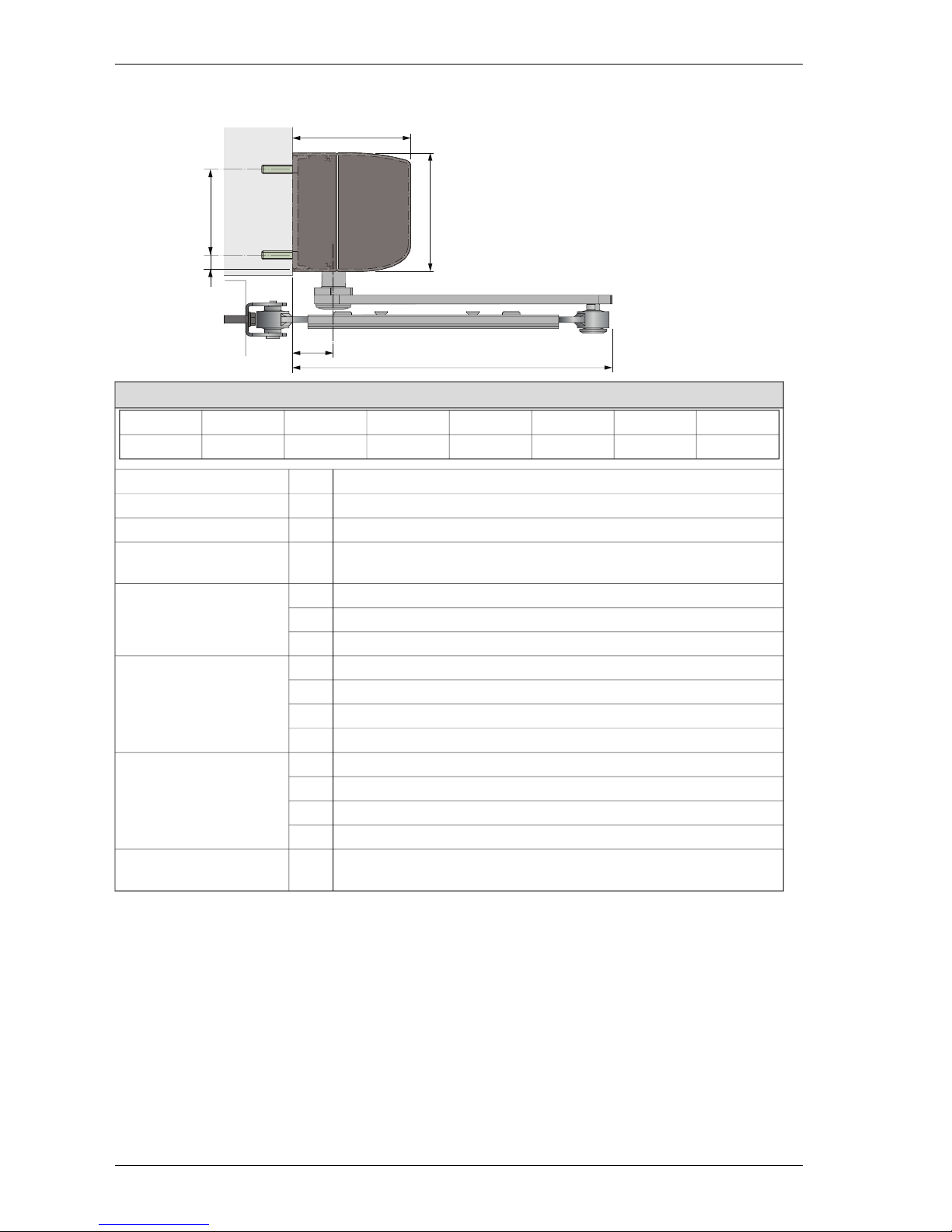
This product is to be installed internally.
38
298
110
110
8013
Classification to DIN 18650-1
Digit 8Digit 7Digit 6Digit 5Digit 4Digit 3Digit 2Digit 1
41,2,3,41,2,3,41,2,32131
swing door drive1Type of drive, digit 1.
1 000 000 test cycles, at 4 000 cycles/day3Drive durability, digit 2.
swing door1Type of door leaf, digit 3.
suitable for use as a fire door2Suitability for use as a fire
protection door, digit. 4
force limitation1Drive safety devices, digit
5.
connection for external safety systems2
low energy3
in escape routes with a break-out system1Special requirements for
drives/functions/fittings,
digit 6.
in escape routes without a break-out system2
for self-closing fire protection doors with a break-out system3
for self-closing fire protection doors without a break-out system.4
with sufficiently dimensioned safety distances1Safety at door leaf or
leaves, digit 7.
with protection to prevent fingers being crushed, shorn off or drawn in2
with integrated break-out unit3
with presence sensor4
temperature range as specified by the manufacturer4Ambienttemperature, digit
8.
1004291-EMEI-10.0Issue 2016-01-2710
4 Technical specification
Page 11

4.1 Permitted door weight and door width
0
50
100
150
200
250
300
350
400
450
0.8 0.9 1 1.1 1.2 1.3 1.4
PUSH arm
PULL arm
J=80 kgm²
J=28 kgm²
PUSH arm
PULL arm
Door weight (kg)
Door width (m)
11Issue 2016-01-271004291-EMEI-10.0
4 Technical specification
Page 12

5 How the EM EMSW works
The EM EMSW works electro-hydraulically. It opens with an AC-motor that via a hydraulicunit and
an arm system transmits the power to the door leaf. The closing power is from a coil spring. The
movement of the door is controlled by limit switches and valve screws.
5.1 Opening
When an opening impulse is received by the control unit, the motor starts and the hydraulic unit
rotates the drive shaft and arm system (door) with high speed towards open position. Before fully
open position, the speed is reduced to low speed. The door stops and the motor rotation ceases
when the selected door opening angle is reached. This open position is kept by a hydraulic valve.
5.2 Closing
The spring closing starts when the hold open time has run out. Before fully closed position the
speed is reduced to low speed, which will be kept until the door is completely closed. The door is
kept closed by spring power. To overcome the resistance of a striking plate a “lock kick” can be
adjusted to required level.
5.3 Functions on the Control Unit CSDB
5.3.1 Key Impulse
Key impulse will open the door in programme selection OFF, EXIT and AUTO and keep the door
open during key hold open time.
Key hold open time can be adjusted between 0-30 sec.
5.3.2 Outer Impulse
Outer impulse will open the doorif programme selection is AUTO and keep the door open during
the outer hold open time, which can be adjusted between 0-30 s.
1004291-EMEI-10.0Issue 2016-01-2712
5 How the EM EMSW works
Page 13
5.3.3 Multi Voltage Input (MVI)
MVI impulse accepts a potential-free contact or 6-24 V AC/DC.
Status of lock (operation mode) can be selected via a function selector FS2 and depends on input
TB2:11 and 13.
TB2:11 and 13
6-24 V AC/DC*
TB2:11 and 13TB2:11 and 13FS-2 = OFF /factory setting)
FS-3 = OFF (factory setting)
AUTO
OFF
CSDB (No PS)
OFFEXB OFF
EXITEXB EXIT
AUTOEXB AUTO
OPENEXB OPEN
TB2:11 and 13
6-24 V AC/DC*
TB2:11 and 13TB2:11 and 13sFS-2 = ON
FS-3 = OFF (factory setting)
OFF
AUTOCSDB (No PS)
OFFEXB OFF
EXITEXB EXIT
AUTOEXB AUTO
OPENEXB OPEN
TB2:11 and 13
6-24 V AC/DC*
TB2:11 and 13TB2:11 and 13FS-2 = OFF (factory setting)
FS-3 = ON
Open doorOFFCSDB (No PS)
Open doorOFFEXB OFF
Open doorEXITEXB EXIT
Open doorAUTOEXB AUTO
Open doorOPENEXB OPEN
TB2:11 and 13
6-24 V AC/DC*
TB2:11 and 13TB2:11 and 13FS-2 = ON
FS-3 = ON
OFFOpen doorCSDB (No PS)
OFFOpen doorEXB OFF
EXITOpen doorEXB EXIT
AUTOOpen doorEXB AUTO
OPENOpen doorEXB OPEN
* +6-24 V DC must be connected to TB2:13 and MVI jumper must be removed.
Programme selector mustnot beconnectedto TB2:13 ifinput is 6-24V.Connectinstead programme
selector to EXB.
MVI impulse willunlock thelock and open the dooror onlyunlock thelock (changes the operation
mode of the operator). Can be selected via the function selector FS3.
MVI hold open time can be adjusted between 0-30 sec.
13Issue 2016-01-271004291-EMEI-10.0
5 How the EM EMSW works
Page 14

5.3.4 Kill Input
When kill is activated, the door will close immediately if not already closed. Hold open and low
pass filter timers are reset.
Key impulse will open lock during activated kill if not connected to TB2:5 for 0 V DC.
When kill is deactivated, the door will act according to current input status.
Several kill inputs are possible to connect in parallel with other CSDB control units. Connect kill
on the first operator according to the connection diagram. The second, third etc. operator is only
to be connected in parallel, from terminal 5 to 5 and 6 to 6.
Kill function is selected via a function selector (Kill jumper).
As an alternative to the shown connection under Connection of activation units and accessories
on page 50, an alarm loop 24 VDC can be connected to the CSDB connect +24 VDC to terminal 6
and 0 VDC to terminal 5.
5.3.5 Limit Switch Open
The limit switch indicates a fully open door and can be adjusted for opening angles up to 120º.
When the limitswitch isactivated the motor will stop.If thelimit switch isnot activated,the motor
will stop after 14 sec.
If the limit switch is deactivated when the door is open, the motor will restart to reposition the
door.
The LED indicates an activated limit switch.
Contact rating: 1A, 48 V DC, normally open.
5.3.6 Home Switch (optional)
When no home switch is mounted and the limit switch is deactivated in open position, a timer
starts and after 6 sec the status will change from closing to closed door.
If the optional home switch is mounted, this will indicate closed door instead of the timer.
“Opening delay” for lock (0-3s) is ignored as soon as home switch is not activated.
“Slave delay” (0,5s) is ignored as soon as home switch for the master is not activated.
Presence impulse is ignored when home switch indicates a closed door within 6 seconds.
The LED indicates an activated home switch.
5.3.7 Lock output
The lock output is short circuit proof and can source a lock with 24V, 375 mA.
The output can be locked with power or locked without power. It can be selected via a function
selector (Locked w. / w.o. power).
The lock activation time can be either 1,5 s + (opening delay) or until closing. It can be selected
via a function selector (Lock time 1,5 s/until closing).
“Opening delay” for lock, the time that will pass before the motor starts, can be adjusted from 0-3
s.
If ahome switch is installed, the lock opening time will first start when thehome switch is deactivated. This to prevent door to jam in the lock, if presence detection is activated.
1004291-EMEI-10.0Issue 2016-01-2714
5 How the EM EMSW works
Page 15

5.3.8 Double Door
The CSDB works as the master in a double door application and is connected to the slave unit
CSDA-S.
The slave unit has a standard opening delay of 0,2 sec. The delay can be increased to 0,5 sec. to
prevent jamming of thicker door leaves. This can be selected via a function selector (Slave Delay).
Home switch is recommended to prevent delay during closing.
When there is a need for more power supply than a single CSDB can deliver, a second CSDB can
be connected as a slave. The CSDB on the slave unit must then be configured as a slave. This can
be selected via a function selector (Master / Slave).
To enable only one door to open, connect impulse parallel on both units. Slave door must have
CSDB+EXB and the low pass filter potentiometer adjusted.
5.3.9 Push to Go
A push on the door will, from closed position, start an automatic opening cycle if the programme
selection is AUTO or EXIT and remain open during the hold open time “Outer HOT” (0-30 s).
A home switch on the operator is needed to achieve Push to Go. Can be selected via a function
selector (Push to Go).
The LED indicates when the home switch is active.
5.3.10 Error Messages
The LED indicates:
• Sensor error; 1 flash of 0,2 sec and then 1 sec pause etc.
• Lock error(too high current draw or short circuit); 1 flash of 0,2sec and then 0,2 sec pause etc.
• CSDB defect; 3 or 4 flashes of 0,2 sec and 0,2 pause
• No slave connected and Slave monitoring jumper is missing; 7 flashes of 0,2 sec and 0,2 pause
• Slave connected but Slave monitoringjumper isnot removed;7 flashes of 0,2 secand 0,2pause
• Defect slave CSDA-S; 7 flashes of 0,2 sec and 0,2 pause
• Old slave connected and Slave monitoring jumper removed; 7 flashes of 0,2 sec and 0,2 pause
5.3.11 Programme Selector
Aprogramme selector PS-3B,with three positionsOFF-AUTO-OPEN,can be connectedto the CSDB.
Note! If the MVI-input is used for 6-24 V, the PS-3B can not be used.
The key impulse is still valid in programme selection OFF.
Presence sensors are enabled in all programme selector settings but not when kill is active.
5.4 Functions on the Extension Unit EXB
5.4.1 Inner impulse
Inner impulse will open the door if programme selection is AUTO or EXIT and keep the door open
during the hold open time.
The hold open time is adjustable from 0-30 sec.
5.4.2 Low Pass Filter (automatic cycle delay)
This function demands a constant inner impulse fora certain timeto start an automatic cycle. The
time can be adjusted from 0-5 sec.
During closing the door will reopen immediately if impulsed.
15Issue 2016-01-271004291-EMEI-10.0
5 How the EM EMSW works
Page 16

5.4.3 Presence Impulse
Presence impulse will prevent an open door from closing and will re-open a closing door and the
control will make sure that the hold open time is not shorter than 1,5 s.
Presence impulse is ignored when home impulse is active.
Presence impulse is not a valid impulse if the door is manually opened.
Presence impulse is a valid impulse if the door is opened with Push to Go.
The inputcan beeither “normally open” or “normally closed”, which can beselected viaa function
selector (Presence Impulse NO/NC).
5.4.4 Presence Detection
Presence Detection will prevent a closed door from opening and stop an opening door.
A blankout switch is used toblank out the sensor fromseeing for instance a wall close to the open
door. There can be two switches overlapping each other for the master door and two for the slave
door.
Two LED’s indicate the blank out switch status. One LED for the master door and one for the slave
door. The LED will light up if either of the two blanking switches is activated.
Presence detection can be selected via two function selectors, “Presence Detect Master” and
“Presence Detect Slave”.
5.4.5 Sensor Monitoring
Test of Presence detection is performed before opening. Test of Presence impulse is performed
before closing. Themaster sensors aretested first andthe slavesensors are testedwhen the answer
is received from master sensors.
If sensor test is not performed successfully the door will enter manual mode and report sensor
error. The sensor test will continue during manual mode.
If no slave operator is present, when sensor monitoring is enabled, the “presence impulse slave”
should be connected to “sensor test slave”.
It is only possible to monitor sensors with output of type normally closed (NC).
If the sensor error disappears during manual mode the door will re-enter automatic mode again.
Monitoring can be selected via a function selector (Presence Sensor Monitoring).
5.4.6 Overhead Presence Detection (OPD)
OPD impulse will prevent a closed door from opening and an open door from closing.
A moving door will ignore the OPD input. The OPD will be active 6 sec. after the door has started
to close. If a home switch is mounted, the OPD will be active as soon as the door is closed.
OPD can be selected via a function selector (Sensor type OPD/Mat).
5.4.7 Mat Safety
Mat safety impulse will prevent a closed door from opening and an open door from closing.
No impulses are accepted during closing if mat is activated.
Mat safety can be selected via a function selector (Sensor type OPD/Mat).
5.4.8 LockOut
LockOut is used to ignore the OPD sensor during opening and closing. Output will be low when
the door isconsidered closed,high during openingand open andtoggling whenthe dooris closing.
LockOut output will be low when the door is manually opened.
1004291-EMEI-10.0Issue 2016-01-2716
5 How the EM EMSW works
Page 17

5.4.9 Programme selector
Programme selector PS-4C can be connected to the EXB.
The PS-4C, compared toPS-3B, hasa fourth position EXIT that will make the CSDB ignore theouter
impulse device.
Presence sensors are enabled in all programme selector settings but not when kill is active.
17Issue 2016-01-271004291-EMEI-10.0
5 How the EM EMSW works
Page 18
6 Models
One main model with standard cover is available of the EM EMSW.
The operator are non-handed and not dependent on the hinges. The operator suits both pushing
and pulling arm systems.
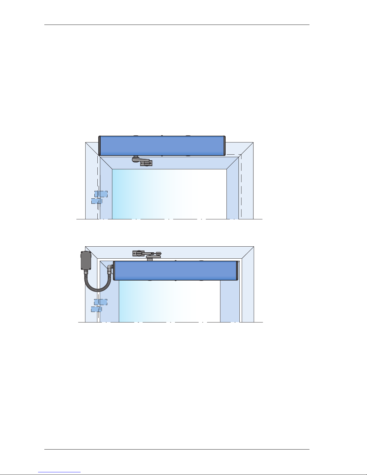
6.1 EM EMSW, standard cover (wall or door leaf mounted)
EM EMSW is the standard operator. Pushing arm system on a wall-mounted and on a door leafmounted operator shown.
Wall mounted
AAD174
Door leaf mounted
ILL-01652
1004291-EMEI-10.0Issue 2016-01-2718
6 Models
Page 19
7 Part identification & Accessories
701500
HSO
HSO
LSO
LSO
LSCLK
HSC
HSC
LSC
701448
LK
12 3 4
TB2
TB2
0 V DC
24 V DC
0 V DC
Kill
Key Impulse
Lock 24 V DC
Kill jumper
MVI N.O. / N.C.
MVI Open Lock / Door
Lock w. / w.o. power
Lock time 1.5 s / until closing
Slave delay off / on
Master / Slave
Push & Go
Outer Impulse
MVI Impulse
1003870
ALL TB1 AND TB2,
CLASS 2 SUPPLY
MAX. 24 V
0 V DC
24 V DC
Motor control
"Slave"
ON
1234 56
78
H.O.T
Opening Delay
MVI H.O.T
1
2
3
4
S
W
5
6
7
8
9
10
11
13
12
14
8
9
7
6
2
3
1
10
11
11
5
L2
C
L1
C
4
15
14
12
13
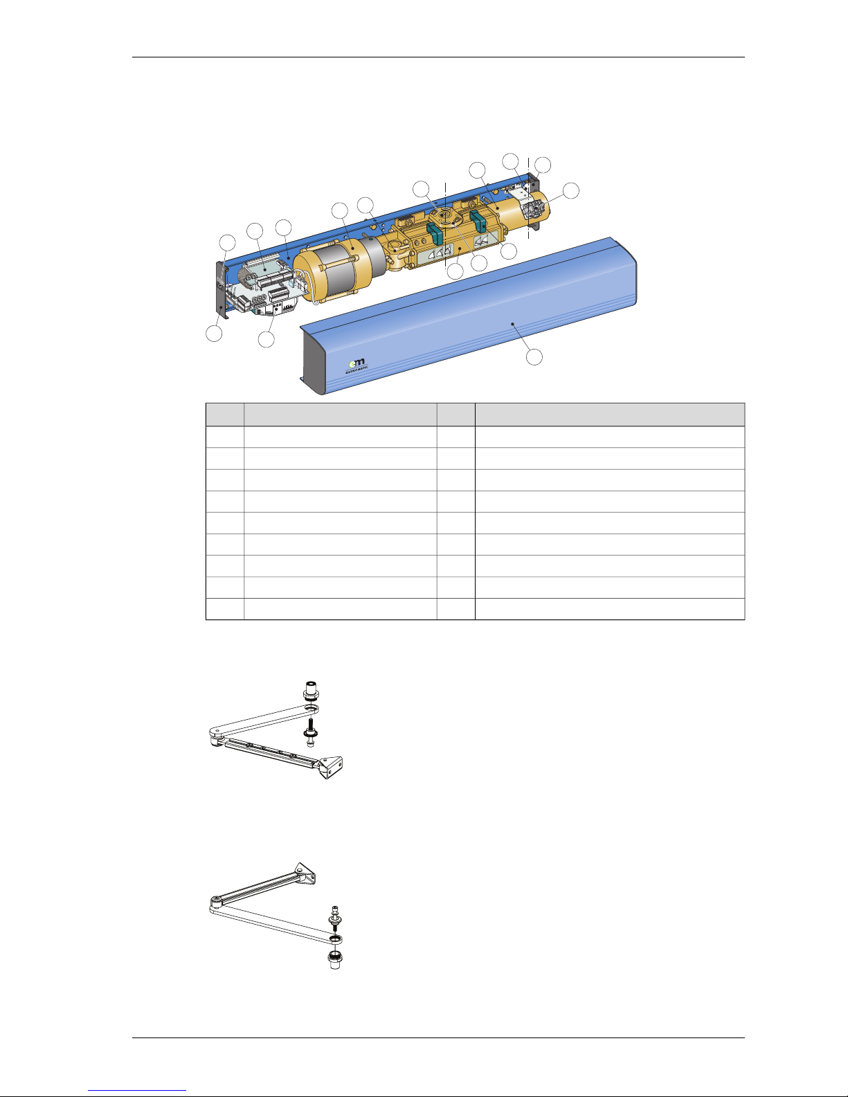
DescriptionNo.DescriptionNo.
Extension unit, EXB (option)10Mounting plate1
End plate11Motor/pump2
Programme selector, PS-3B (option)12Magnetic valve3
Cover13Hydraulic unit4
Bearing sleeve14Drive shaft5
Cable holder15Spring tube6
Centre line, drive shaftCL1=Cable inlet7
Centre line, hingeCL2=Mains connection8
Control unit, CSDB9
7.1 Arm systems, PUSH
Art. No. 1014113BK/SI
PUSH
It is used if the operator is installed on the wall on the opposite side of
the door swing and approved for fire applications.
7.2 Arm systems, PUSH-335
Art. No. 1011706BK/SI
PUSH-335
It is used if the operator is installed on the door leaf hinge side.
19Issue 2016-01-271004291-EMEI-10.0
7 Part identification & Accessories
Page 20

7.3 Arm system, PULL
Art. No. 1011707BK/SI
PULL
It is used if the operator is installed on the wall on the same side as the
door swing.
7.4 Arm system, PULL-220
Art. No. 1014114BK/SI
PULL-220
It is used if the operator is installed on the wall on the same side as the
door swing and when the door is 450-700 mm wide.
7.5 Arm system, ST-V / ST-H
ST-V, Art. No. 172312SI, 172313BK
ST-H, Art. No. 172314SI, 172315BK
Note! Door fitting not included.
It is used if the operator is installed on the wall on the same side as the
door swing and break-out unit is required.
7.5.1 Options for ST-V / ST-H
Door fitting standard
Art. No.: 172071
Door fitting Break-out
Art. No. 172325 for pivot (break-out) door, right when the reveal A = 0-60 mm (0-2 3/8”) or left
when A > 60-100 mm (>2 3/8”-3 15/16”) for ST-H/ST-V
Art. No. 172327 for pivot (break-out) door, right when A > 60-100 mm (>2 3/8”-3 15/16”) or left
when A = 0-60 mm (0-2 3/8”)
Arm extension
Art. No. 172320 required when the reveal A >60-100 mm (>2 3/8”-3 15/16”)
1004291-EMEI-10.0Issue 2016-01-2720
7 Part identification & Accessories
Page 21
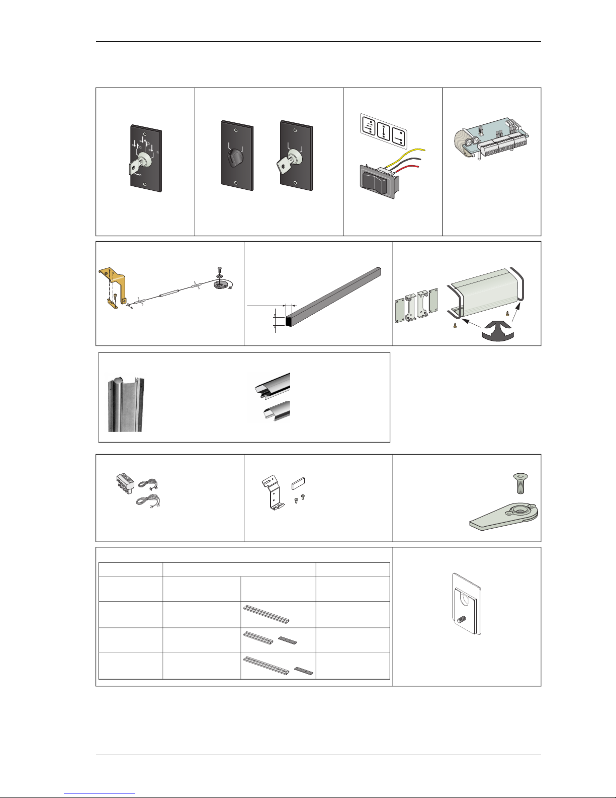
7.6 Further accessories
Extension unit3-Position2-Position Switch4-Position Switch
EXBSwitch PS-3B
PSK-2PSW-2
0
1
0
1
ILL-01578
Art. No.
655844
Art. No.
655843
(with EXB)
PS-4C
Art. No.
655845
Art. No. 1004116
Art. No. 1004117
Middle piece kitPULL-Arm Reveal SpacerCoordination unit, COOA
Art. No. 1008385Art. No. 1014667BK/SI
40 mm (1-37/64")
60 mm
(2-23/64")
Art. No. 100091
Finger protection strips
Art. No. 833334Art. No. 833333
Door stopPCB Attachment plateCable kit slave
Art. No. 100147
Art. No. 1003884
Art. No. 656064
1
2
3
4
S
W
Cable inletPUSH, Arm Extensions
Art. No. 1007567
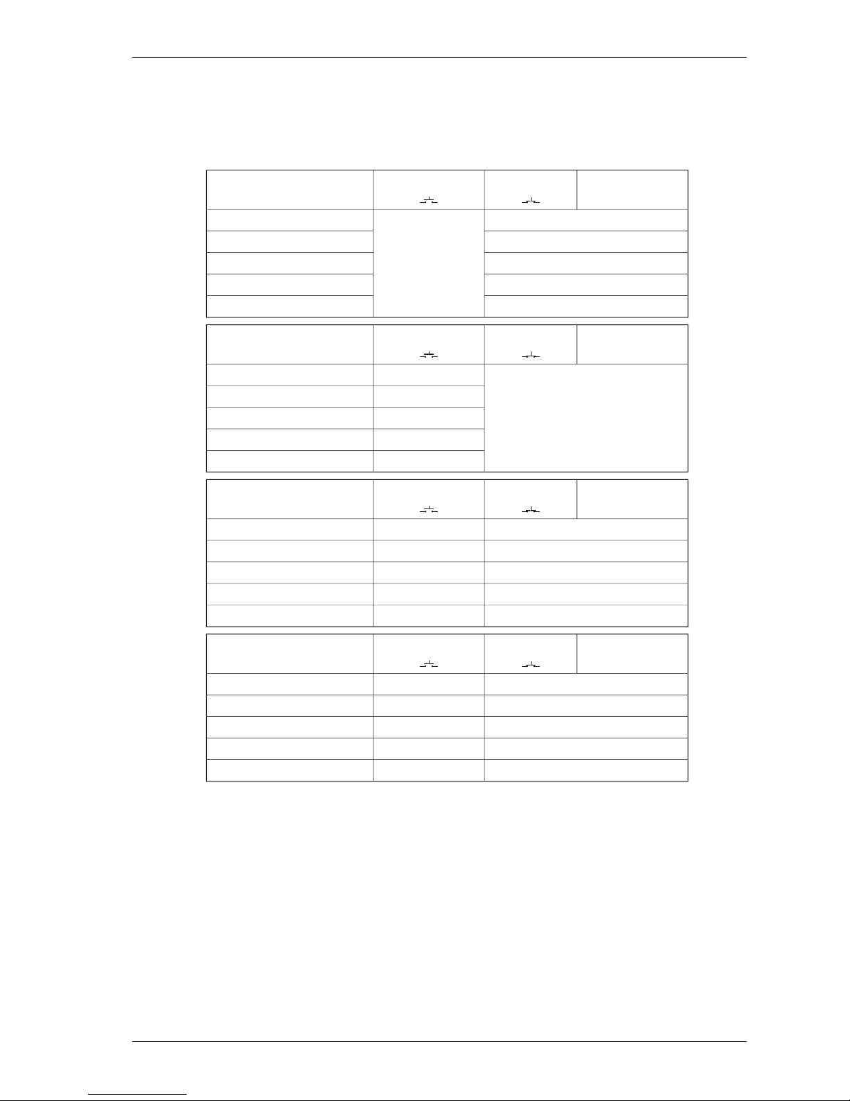
Art. No.ExtensionReveal
--None (Standard arm)0-110 mm
Up to 4-3/8”
173005BK/SI345 mm110-235 mm
4-3/8” to 9-1/4”
173004BK/SI +
173191
+
230 mm + Joint part235-360 mm
9-1/4” to 14-1/8”
173005BK/SI +
173191
+
345 mm + Joint part360-485 mm
14-1/8” to 19”
21Issue 2016-01-271004291-EMEI-10.0
7 Part identification & Accessories
Page 22

Control unit, CSDA-F
Art. No. 600081
Drive Shaft Extension Kits
20 mm
(3/4")
50 mm
(2")
70 mm
(2-3/4")
Art. No.
173109/173109SI
Art. No.
173108/173108SI
Art. No.
173107/173107SI
Drilling template
Art. No. 1000219
Limit SwitchRestore after alarm buttonTool kit to change rotation direction
Art. No. 655614 (L = 500 mm)Art. No. 600090Art. No. 173719
Art. No. 1004205 (L = 2000 mm)
Smoke Detector ORS 142
Art. No. 738794
Ceiling socket 143W
for smoke detector
Art. No. 738795
Ceiling socket 143A
for smoke detector
Art. No. 738795
Shaft extension, SEKDoor mounting kitMounting plate
(including bearing for extension 70-420
mm)
Art. No. 173039
8x
2x
(for door leaf mounted operators)
Art. No. 100132
Art. No.T
(mm)
H
(mm)
L
(mm)
1736806125
State
1736618160
1004291-EMEI-10.0Issue 2016-01-2722
7 Part identification & Accessories
Page 23

7.7 Labels
Label kit - including all below
Art. No. 1005227
Emergency break-out, DIN right door
Art. No. 1001785
Emergency break-out, DIN left door
Art. No. 1001786
Activation by disabled people
Art. No. 1003963
Click!
Operator designed for disabled people
Art. No. 1003964
Supervision of child
Art. No. 1001695
23Issue 2016-01-271004291-EMEI-10.0
7 Part identification & Accessories
Page 24

8 Pre-Installation
8.1 General tips/Safety concerns
In all instances, where work is being done, the area is to be secured from pedestrian traffic, and the power removed to prevent injury.
• If there are sharp edges after drilling the cable outlets, chamfer the edges to avoid damage to
the cables.
• For enhanced security and vandalism protection, always mount the operator access in the interior of a building whenever possible.
• Make sure the ambient temperatureis in the range specified in section Technical specification.
• Make sure that the power is off before installing.
• Make sure that the door leaf and the wall are properly reinforced at the installation points.
• Unpack the operator and makesure that all parts are delivered in accordance with the packing
note and that the operator is in good mechanical condition.
• Ensure proper material is being used for the door leaves and that there are no sharp edges.
Projecting partsshall not create any potential hazards. If glassis used bare glass edges shall not
come in contact with other glass. Toughened or laminated glass are suitable glasses.
• Ensure that entrapment between the driven part and the surrounding fixed parts due to the
opening movement ofthe driven partisavoided. Thefollowingdistances areconsideredsufficient
to avoid entrapments for the parts of the body identified;
- for fingers, a distance greater than 25 mm or less than 8 mm
- for heads, a distance greater than 200 mm
- for feet, a distance greater than 50 mm
- and for the whole body, a distance greater than 500 mm
• Danger points shall be safe guarded up to a height of 2.5 m from the floor level.
• The operator shall not be used with a doorset incorporating a wicket door.
It is not possible to replace a EM operator component with a component from
a different brand.
8.2 Fastening requirements
Minimum requirements of wall profile*Base material
5 mm **Steel
6 mm **Aluminium
min. 50 mm from the undersideReinforced concrete
50 mmWood
Expansion shell bolt, min. M6x85, UPAT PSEA B10/25, min. 50
mm from the underside
Brick wall
* Entrematic Group minimum recommended requirements. Building Codes may give different
specifications. Refer to AHJ (Authority Having Jurisdiction).
** Thinner wall profiles must be reinforced with rivnuts.
1004291-EMEI-10.0Issue 2016-01-2724
8 Pre-Installation
Page 25

8.3 Tools required
• Torx T8, T10, T20 and T25
• Metric hexagonal key 3, 4 and 6 mm
• Flatblade screwdriver, small
• Torque wrench with metric Allen socket 6 mm
8.4 Installation on double doors
If the operators are to be mounted at the same height with pushing and pulling arm systems, the
height is determinedby the pullingarm system, PULL/ST. Thepushing arm systemPUSH mustalways
have a shaft extension, minimum 50 mm.
Example: If PULL has a 20 mm extension, the PUSH must have a 70 mm extension.
For installation follow the instructions for the applicable arm system.
25Issue 2016-01-271004291-EMEI-10.0
8 Pre-Installation
Page 26

8.5 Installation examples for fire approved doors
Illustrations below show examples of approved reinforcements when mounting a fireproof swing
door operator.
Note! The type approval for fireproof swing doors is valid only with the arm system PUSH. Reveal
max 480 mm and shaft extension max 70 mm.
Min.
45
Min.
45
2
1
2
7
8
4
2
6
8
3
5
9
DescriptionNo.DescriptionNo.
Wood screw M6, KST, L=45 (2x)6Steel min. 50x5, L=min.100, centered for mountingholes
(4x)
This is a requirement with aluminium profiles.
Screw M6, FS-TT FZB, Taptite, L=40 (4x)
1
Rivnut M6, FTT/ST, L=15,9 (4x)
Screw M6, FS-TT FZB Tabtite, L=40 (4x).
Rivnuts are only allowedtobe used with steelprofileswith
thickness of min 1,5 mm.
7Steel min. 50x5, L=min. 150, centered at the arms length
on the door.
This is a requirement with aluminium profiles.
Screw M6, FS-TT FZB, Tabtite, L=40 (2x).
2
Rivnut M6, FTT/ST, L=15,9 (2x)
Screw M6, FS-TT FZB, Tabtite, L=40 (2x).
Rivnuts are only allowed to be used with steel profiles
8Steel min. 50x5,L=min.100, centered for mountingholes
(4x)
This is a requirement with aluminium profiles.
Screw M6, FS-TT FZB, Tabtite, L=50 (4x) Distance piece
ø10/13
3
Rivnut M6, FTT/ST, L=15,9 (4x)
Screw M6, FS-TT FZB, Tabtite, L=50 (4x)
Distance piece ø10/13.
Rivnuts are only allowed to be used together with a plas-
terboard beam made of steel with a material thickness of
min 1,5 mm.
9Expansion-shell bolt (4x)
(for brickwall min. M6x85, UPAT PSEA B 10/25)
4
Wood screw M6, KST, L=min. 70 (4x)
Distance piece ø10/13
5
1004291-EMEI-10.0Issue 2016-01-2726
8 Pre-Installation
Page 27

9 Mechanical installation
This instruction comprises the installation of the EM EMSW with arm systems PUSH, which push
the door openand PULL / ST-V/H, which pullthe door open.See also“QuickStart” which isenclosed
with each operator.
9.1 Wall mounted operator with arm system PUSH
1
80
13
X
Y
0-110 (485)
C
L
1
Y
45
248
X
2
X
ø 5,1 mm, 8x
102
217
364
13
2 – 17 48
2 – 37 68
2 – 67 98
2 – 87
X Y
20
50
70 118
C
L
2
Drilling template
Art. No. 1000219
27Issue 2016-01-271004291-EMEI-10.0
9 Mechanical installation
Page 28

Cont. “Wall mounted operator with arm system PUSH”
6
5
701500
HSO
HSO
LSO
LSO
LSCLK
HSC
HSC
LSC
701448
LK
C
L
1
C
L
2
4
C
L
1
210
701500
HSO
HSO
LSO
LSO
LSCLK
HSC
HSC
LSC
701448
LK
C
L
2
2x
C
L
1
3
25
ø 16 mm
15
(Cable inlet hole)
1004291-EMEI-10.0Issue 2016-01-2728
9 Mechanical installation
Page 29

Cont. “Wall mounted operator with arm system PUSH”
7b
7
9
90°
60
90°
Adjust +/– 1 tooth = ±5°
7a
I
I
I
I
I
I
I
I
I
I
I
I
I
I
I
I
25 Nm
8
29Issue 2016-01-271004291-EMEI-10.0
9 Mechanical installation
Page 30

9.2 Door leaf mounted operator with arm system PUSH-335
716
0
0
1
max. 135
min. 45
min. 120
C
L
1
C
L
2
245 45
210
180
108,5
108,5
2
110
110
3
3
80 4813
min. 5017
min. 45
min. 120
min. 50
max. 135
Pivot or butt hinges
CL1
Operator drive shaftCL2
Cable inlet at end plate1
Door mounting kit,Art. No. 100132,
optional
2
Reinforcements required indoorleaf
and at the fixing holes
3
1004291-EMEI-10.0Issue 2016-01-2730
9 Mechanical installation
Page 31

9.3 Wall mounted operator with arm system PULL, PULL-220 and ST
Note! If the operator is not ordered for pulling arm system, the direction of rotation must be reversed.
9.3.1 Changing the direction of rotation
701500
HSO
HSO
LSO
LSO
LSCLK
HSC
HSC
LSC
701448
LK
701500
HSO
HSO
LSO
LSO
LSCLK
HSC
HSC
LSC
701448
LK
701500
HSO
HSO
LSO
LSO
LSCLK
HSC
HSC
LSC
701448
LK
701500
HSO
HSO
LSO
LSO
LSCLK
HSC
HSC
LSC
701448
LK
701500
HSO
HSO
LSO
LSO
LSCLK
HSC
HSC
LSC
701448
LK
701500
HSO
HSO
LSO
LSO
LSCLK
HSC
HSC
LSC
701448
LK
1 2
3 4
5 6
165˚
30
(1 3/16")
34
(1 11/32")
30 34
(1 11/32")(1 3/16")
ILL-01556
31Issue 2016-01-271004291-EMEI-10.0
9 Mechanical installation
Page 32

9.3.2 Installation of operator with arm system PULL
80
13
46
66
96
116
Z
20
50
70
_
40 x 60
10
Z
≤ 60
1
C
L
1
652
74
Z10
2
Z
ø 5,1 mm, 8x
102
217
364
13
Top of door
Drilling template
Art. No. 1000219
(turnable)
1004291-EMEI-10.0Issue 2016-01-2732
9 Mechanical installation
Page 33

Cont. “Installation of operator with arm system PULL”
701500
HSO
HSO
LSO
LSO
LSCLK
HSC
HSC
LSC
701448
LK
C
L
1
C
L
2
4
3
C
L
1
210
701500
HSO
HSO
LSO
LSO
LSCLK
HSC
HSC
LSC
701448
LK
C
L
2
6x
5
0 V DC
24 V DC
TB
1 AN
D TB
2,
CLA
SS 2 S
UPPL
Y
MAX
. 24
V
5
6
7
8
9
10
11
13
12
14
TB2
C
L
1
25
ø 16 mm
15
(Cable inlet hole)
Connect mains power
33Issue 2016-01-271004291-EMEI-10.0
9 Mechanical installation
Page 34

Cont. “Installation of operator with arm system PULL”
7
8
9
I
I
I
I
I
I
I
I
I
I
I
I
I
I
I
I
I
25 Nm
C
L
1
C
L
2
C
L
2
2x
6
701500
HSO
HSO
LSO
LSO
HSC
701448
C
L
2
701500
HSO
HSO
LSO
LSO
LSCLK
HSC
HSC
LSC
701448
LK
1004291-EMEI-10.0Issue 2016-01-2734
9 Mechanical installation
Page 35

Cont. “Installation of operator with arm system PULL”
0 V DC
24 V DC
CLASS 2 SUPPLY
MAX. 24 V
5
6
7
8
9
10
11
13
12
14
TB2
11
10
Click
Click
701500
HSO
HSO
LSO
LSO
LSCLK
HSC
HSC
LSC
701448
LK
701500
HSO
HSO
LSO
LSO
LSCLK
HSC
HSC
LSC
701448
LK
35Issue 2016-01-271004291-EMEI-10.0
9 Mechanical installation
Page 36

9.3.3 Installation of operator with arm system ST
80
13
40
61
A
1
C
L
1
6140
2
61
ø 5,1 mm, 6x
2x
102
81
217
364
A > 60 - 100
A = 0 - 60
C
L
2
Top of door
Drilling template
Art. No. 1000219
(Optional)
Outside open door
1004291-EMEI-10.0Issue 2016-01-2736
9 Mechanical installation
Page 37

Cont. “Installation of operator with arm system ST”
3
25
96
4
291
701500
HSO
HSO
LSO
LSO
LSCLK
HSC
HSC
LSC
701448
LK
C
L
2
6x
ø 16 mm
Outside open door
(Cable inlet hole)
Outside open door
37Issue 2016-01-271004291-EMEI-10.0
9 Mechanical installation
Page 38

Cont. “Installation of operator with arm system ST”
7
6
C
L
2
701500
HSO
HSO
LSO
LSO
LSCLK
HSC
HSC
LSC
701448
LK
5
C
L
2
0 V DC
24 V DC
CLASS 2 SUPPLY
MAX. 24 V
5
6
7
8
9
10
11
13
12
14
TB2
701500
HSO
HSO
LSO
LSO
LSCLK
HSC
HSC
LSC
701448
LK
701500
LSO
143
Connect mains power
Note, the way of mounting the arm!
1004291-EMEI-10.0Issue 2016-01-2738
9 Mechanical installation
Page 39

Cont. “Installation of operator with arm system ST”
9
10
701500
HSO
HSO
LSO
LSO
LSCLK
HSC
HSC
LSC
701448
LK
0 V DC
24 V DC
CLASS 2 SUPPLY
MAX. 24 V
5
6
7
8
9
10
11
13
12
14
TB2
0º
10a
10b
10c
≈ 45º
≈ 90º
8
I
I
I
I
I
I
I
I
I
I
I
I
I
I
I
I
I
25 Nm
C
L
2
39Issue 2016-01-271004291-EMEI-10.0
9 Mechanical installation
Page 40

Cont. “Installation of operator with arm system ST”
11
701500
HSO
HSO
LSO
LSO
LSCLK
HSC
HSC
LSC
701448
LK
12
701500
HSO
HSO
LSO
LSO
LSCLK
HSC
HSC
LSC
701448
LK
310
210
=
=
Break-out
1004291-EMEI-10.0Issue 2016-01-2740
9 Mechanical installation
Page 41

Cont. “Installation of operator with arm system ST”
ø 5,1 mm, 2x
13
14
2x
701500
HSO
HSO
LSO
LSO
LSCLK
HSC
HSC
LSC
701448
LK
2x
701500
HSO
HSO
LSO
LSO
LSCLK
HSC
HSC
LSC
701448
LK
41Issue 2016-01-271004291-EMEI-10.0
9 Mechanical installation
Page 42

10 Electrical connection
Note! During any work with the electrical connections the mains power must be disconnected.
• Place the electric switch easily accessible from the operator. If a plug contact is used in the installation the wall socket shall be placed easily accessible from the operator.
• If the supply cord is damaged, it must be replaced by the manufacturer, its service agent or
similarly qualified persons in order to avoid a hazard.
10.1 Control units
The operator can be equipped with different control units adapted to the functions required.
10.1.1 CSDB
This basiccontrol unit is equipped with inputs for connectionof automatic and manual activation
units such as radars, photocells, normal push buttons, emergency push buttons etc. Electromechanical striking-plate and slave control unit CSDA-S for double doors can be connected.
10.1.2 CSDA-S
This slave control unit is used together with CSDB for double doors as explained above.
10.1.3 EXB
This extension unit is mounted on top of the CSDB to extend the CSDB functions with inputs for
presence impulse, presence detection, inner impulse, off and exit.
10.1.4 CSDA-F
This unit is, together with CSDB, mainly used for fire doors. Electro-mechanical striking-plate 24 V
AC can be connected.
1004291-EMEI-10.0Issue 2016-01-2742
10 Electrical connection
Page 43

10.2 Connection of control unit CSDB – single doors
Connect the mains power to the mains terminal block.
Note! Accessories and activation units must not be connected until the adjustment of speeds etc.
has been carried out.
Note! It is important that the high and low voltage cables are well separated and fixed. The high
voltage cables must be routed and fixed on one side of the drive unit by using the enclosed cable
holders and the low voltage cables must be
routed on the opposite side using the same type of cable holders.
1 2 3 4
TB2
TB2
Kill jumper
MVI N.O. / N.C.
MVI Open Lock / Door
Lock w. / w.o. power
Lock time 1.5 s / until closing
Slave delay off / on
Master / Slave
Push & Go
1003870
0 V DC
24 V DC
Motor control
"Slave"
ON
H.O.T
Opening Delay
MVI H.O.T
LSCLK
HSC
LSC
LK
5
6
7
8
9
10
11
12
13
14
1
2
3
4
S
W
TB1
TB2
FS
ON
1
2
3
4
5
6
7
8
(–)
(–)
(+)
(+)
max. 700 mA
N L
F2 = 250 mAT
F1 = 6,3 ATH
TB2
TB1
FS
LED
12 34
TB2
TB2
0 V DC
24 V DC
0 V DC
Kill
Key Impulse
Lock 24 V DC
Kill jumper
MVI N.O. / N.C.
MVI Open Lock / Door
Lock w. / w.o. power
Lock time 1.5 s / until closing
Slave delay off / on
Master / Slave
Push & Go
Outer Impulse
MVI Impulse
1003870
ALL TB1 AND TB2,
CLASS 2 SUPPLY
MAX. 24 V
0 V DC
24 V DC
Motor control
"Slave"
ON
1
234 567 8
H.O.T
Opening Delay
MVI H.O.T
1
2
3
4
S
W
5
6
7
8
9
10
11
13
12
14
Limit switch open
Home switch
Opening valve
Mains power
230 V AC - 50 Hz,10A
F2= 250 mAT
F1= 6,3ATH
MVI / Key HOT
Opening delay
Outer HOT
Sensor Monitoring
OFF / ON
Kill jumper
MVI NO / NC
MVI Open Lock / Door
Locked w. / wo. power
Locked tome 1.5 s until closing
Slave delay off / on
Master / Slave
Push to Gp
Kill -
Kill +
1)
0 V DC
Key Impulse
Lock
24 V DC, 375 mA
0 V DC
24 V DC
MVI Impulse
Outer Impulse
Motor control
0 V DC
Slave control
24 V DC
MVI Jumper 2)
1) See page 48 when connecting "Kill"
2) If 6-24 VDC on TB2: 11-13, remove jumper
3) Remove jumper when connecting ta slave CSDA-S (but
not when connecting to slave CSDB).
Slave monitoring jumper 3)
Slave feed back
Watchdog
max. 700 mA
43Issue 2016-01-271004291-EMEI-10.0
10 Electrical connection
Page 44

10.3 Connection of control units CSDB and CSDA-S – double doors
For double door operators, both operators have to be connected to the mains. A six-pole cable
(enclosed) has to be connected between TB1 on the CSDB and TB6 on the CSDA-S.
Note! It is important that the high and low voltage cables are well separated and fixed. The high
voltage cables must be routed and fixed on one side of the drive unit by using the enclosed cable
holders and the low voltage cables must be routed on the opposite side using the same type of
cable holders.
12 34
TB2
TB2
0 V DC
24 V DC
0 V DC
Kill
Key Impulse
Lock 24 V DC
Kill jumper
MVI N.O. / N.C.
MVI Open Lock / Door
Lock w. / w.o. power
Lock time 1.5 s / until closing
Slave delay off / on
Master / Slave
Push & Go
Outer Impulse
MVI Impulse
1003870
ALL TB1 AND TB2,
CLASS 2 SUPPLY
MAX. 24 V
0 V DC
24 V DC
Motor control
"Slave"
ON
1
234 567 8
H.O.T
Opening Delay
MVI H.O.T
5
6
7
8
9
10
11
13
12
14
W
S
4
3
2
1
F1
TB1
TB1
CSDB
N L
F2
LSCLK
HSC
HSC
LSC
701448
LK
NL
TB6
TB6
CSDA-S
F2 = 250 mAT
F1 = 6,3 ATH
1
2
3
4
S
W
1
2
3
4
S
W
1
2
3
4
S
W
1 2 3 4
TB2
Kill jumper
MVI N.O. / N.C.
MVI Open Lock / Door
Lock w. / w.o. power
Lock time 1.5 s / until closing
Slave delay off / on
1003870
0 V DC
24 V DC
Motor control
"Slave"
ON
1
2
3
4
S
W
ON
1
2
3
4
5
6
7
8
Motor control
0 V DC
Slave control
24 V DC
Motor control
0 V DC
Slave control
24 V DC
Limit switch open
Mains power
230 V AC - 50 Hz,10A
Mains power
230 V AC - 50 Hz,10A
Opening valve
F2= 250 mAT
F1= 6,3 AT
Slave feed back
Watchdog
Watchdog
Slave monitoring Jumper.
Remove when connecting to slave
CSDA-S.
Slave feed back
1004291-EMEI-10.0Issue 2016-01-2744
10 Electrical connection
Page 45

10.4 Connection of control units CSDB/CSDB – double doors
For double door operators both operators have to be connected to the mains. A three-pole cable
(not enclosed) has to be connected between TB1 on the CSDB (master) and TB2 on the CSDB
(slave).
Note! It is important that the high and low voltage cables are well separated and fixed. The high
voltage cables must be routed and fixed on one side of the drive unit by using the enclosed cable
holders and the low voltage cables must be routed on the opposite side using the same type of
cable holders.
Door mounted sensors must be connected to it's own master and slave CSDB/EXB.
1 2 3 4
TB2
Kill jumper
MVI N.O. / N.C.
MVI Open Lock / Door
Lock w. / w.o. power
Lock time 1.5 s / until closing
Slave delay off / on
Master / Slave
Push & Go
1003870
0 V DC
24 V DC
Motor control
"Slave"
ON
H.O.T
1
2
3
4
S
W
5
6
7
12 34
TB2
TB2
0 V DC
24 V DC
0 V DC
Kill
Key Impulse
Lock 24 V DC
Kill jumper
MVI N.O. / N.C.
MVI Open Lock / Door
Lock w. / w.o. power
Lock time 1.5 s / until closing
Slave delay off / on
Master / Slave
Push & Go
Outer Impulse
MVI Impulse
1003870
ALL TB1 AND TB2,
CLASS 2 SUPPLY
MAX. 24 V
0 V DC
24 V DC
Motor control
"Slave"
ON
123
4
567 8
H.O.T
Opening Delay
MVI H.O.T
5
6
7
8
9
10
11
13
12
14
F1
CSDB
N L
F2
1
2
3
4
S
W
TB1
CSDB
CSDB
8
7
6
5
4
3
2
1
9
10
NL
TB2
LSCLK
HSC
HSC
LSC
701448
LK
Slave
Master
FS
FS-7 = ON
1
ON
2
3
4
5
6
7
8
5 6 7 8
TB2
9 10 11121314
(–)
(+)
(+)
F2 = 250 mAT
F1 = 6,3 ATH
max. 700 mA
TB1
1
2
3
4
S
W
Mains power
230 V AC - 50 Hz,10A
F2= 250 mAT
F1= 6,3 AT
Motor control
0 V DC
Slave control
24 V DC
Kill -
Kill +
0 V DC
Key Impulse
Lock
24 V DC, 375 mA
0 V DC
24 V DC
MVI Impulse
Outer Impulse
Mains power
230 V AC - 50 Hz,10A
Adjust opening
delay to "0"
Adjust MVI / Key
Hot to "0"
Slave feed back
Watchdog
45Issue 2016-01-271004291-EMEI-10.0
10 Electrical connection
Page 46

10.5 Connection of extension unit EXB – option
The extension unit EXB is to be installed on top of the CSDB.
a Connect the flat cable on the EXB to the CSDB.
b Snap on the EXB to the CSDB.
HSO
LSCLK
HSC
HSC
LSC
701448
LK
12 34
TB2
TB2
0 V DC
24 V DC
0 V DC
Kill
Key Impulse
Lock 24 V DC
Kill jumper
MVI N.O. / N.C.
MVI Open Lock / Door
Lock w. / w.o. power
Lock time 1.5 s / until closing
Slave delay off / on
Master / Slave
Push & Go
Outer Impulse
MVI Impulse
1003870
ALL TB1 AND TB2,
CLASS 2 SUPPLY
MAX. 24 V
0 V DC
24 V DC
Motor control
"Slave" control
ON
H.O.T
Opening Delay
MVI H.O.T
5
6
7
8
9
10
11
13
12
14
5
6
7
8
9
10
11
13
12
14
20
21
22
23
24
25
26
27
28
29
30
31
32
33
34
35
36
37
20 2122 23
TB3
24 25
26 27 28 29
TB4
30 3132
33 34 35 36
TB5
37
Blanking switch
Presence detect Slave
Blanking LED
Blanking switch
Presence detect Master
OPD / MAT
Sensor type
Presence impulse configuration
NC / NO*
Presence detect Slave
Presence impulse Slave
Presence impulse Master
Presence detect Master
Low pass filter
Inner HOT
0 V DC
24 V DC
Presence detect slave
Sensor test slave
0 V DC
24 V DC
Presence detect master
Sensor test master
Lock out
OPD / MAT
24 V DC
EXIT
OFF
0 V DC
Inner impulse
0 V DC
Presence impulse master
Presence impulse slave
* When selecting NO, remove both jumpers
for presence impulse Master and Slave.
Note! It is important that the high and low voltage cables are well separated and fixed. The high
voltage cables must be routed and fixed on one side of the drive unit by using the enclosed cable
holders and the low voltage cables must be routed on the opposite side using the same type of
cable holders.
1004291-EMEI-10.0Issue 2016-01-2746
10 Electrical connection
Page 47

10.6 Sensor cable inlet
15
,
5
12
2
9
ø 3,7
1 2
8
4 5
6 7
3
Alt. 1
8
Alt. 2
Alt. 1
Alt. 2
Alt. 1
Alt. 2
47Issue 2016-01-271004291-EMEI-10.0
10 Electrical connection
Page 48

11 Start-Up
Adjust the operator to have maximum 25% duty cycle, which means motor run time.
Give a short opening impulse bystrapping theimpulse inputand adjustif necessaryas follows.See
also illustration under Closing torque.
See the “Guide for installers of Powered Pedestrian Swing Doors”, document PRA-0006, for calculation of speed.
a Set the hold open time with the potentiometer on the control unit.
b Adjustment of the opening speed.
• Adapt the high speed opening HSO, to the existing traffic situation. Turning clockwise decreases the speed.
• The low speedopeningLSO, needs tobe adjusted onlyif the doorisextremely heavy.Turning
clockwise decreases the speed.
Note! If it is hard to obtain an even and smooth braking, the opening torque (pump pressure)
must be reduced.
c Adjustment of the closing speed.
• Adjust the low speed closing LSC as low as the traffic situation allows. Turning clockwise
decreases the speed.
• If a higher closing speed is required, open the high speed closing valve HSC (closed from
factory).
Note! If the installation requires adjustment of the closing torque follow the instructions on
page 48.
d Fine-adjust the openingangle bymeans of thelimit switch.Thelimit switch isslid into agroove
in the hydraulic unit and tightened with a lock screw. By moving the limit switch sideways, the
opening angle is changed.
Note! To make the adjustment easier, the limit switch can be moved to the underside of the
hydraulic unit. Any of the grooves at the motor side of the outgoing shaft can be used.
e If an electromechanical striking plate is installed, an additional “lock-kick” can be obtained
during the last 5° of the closing cycle by adjusting thescrew LKon thehydraulic unit.This screw
is normally closed. Adjust by opening the screw 90° and check the function.
Note! Opening the screw too much may delay the opening.
f Connect the activation units.
g Check that the installation complies with valid regulations and requirements from the author-
ities.
h Special careshould be takenregarding entrapment betweendriven partsand surrounding fixed
parts.
11.1 Closing torque
To comply with authority requirements or to overcome over/under pressure the closing torque
can be adjusted.
The closing torque (spring force) is adjusted by means of an Allen screw placed at the end of the
spring tube. The end plate has to be dismantled. Turning the screw clockwise increases the force.
One turn equals a torque change of approx. 1 Nm (28 turns from min. to max.). The door must be
in open position when extremely low torque is adjusted.
Note! Max opening force in escape route is 150 N.
1004291-EMEI-10.0Issue 2016-01-2748
11 Start-Up
Page 49

11.2 Opening torque
If the closing torque (spring force) has been changed, or if the door does not open to its full extent,
the opening torque (pump pressure) must be adjusted as follows:
a The factory set torque for PUSH is 70 Nm and for PULL 40 Nm at a door opening angle of 0-2°.
b Measure the opening torque by using a spring balance and adjust if necessary.
The torque isadjusted by meansof an Allenscrew placed onthe pump. Turning clockwise increases
the opening torque/pump pressure. One turn equals a torque change of approx. 30 Nm.
701500
HSO
LSO
LSO
HSO
LSCLK
HSC
LSC
701448
LK
HSC
3 mm
LSO
HSO
LK
F
5°
3 mm
10 mm
POCKET
BALA
NCE
0 0
2 2
4
4
6
6
8 8
10
10
12 12
14 14
16
16
18
18
20 20
22 22
25
25
PUSH = 70 N
PULL = 40 N
F
POCKET
BALANCE
0 0
2 2
4
4
6
6
8 8
10
10
12
12
14 14
16
16
18
18
20
20
22 22
25
25
5°
PUSH = 35 N
PULL = 20 N
6 mm
2 mm
LSC
HSC
49Issue 2016-01-271004291-EMEI-10.0
11 Start-Up
Page 50

11.3 Connection of activation units and accessories
See sensormanuals formounting and adjustments. Protective device shall comply with EN12978.
AK / ES-P
PB…
123
1234567
R2
25 2020 21 21
EXB/TB3
EXB/TB4
32 30 3126
GND
EYE-TECHBodyguard
4 SAFE
7 8 1211 8
CSDB/TB2
CSDB/TB2
CSDB/TB2
6 - 24 V AC/DC
71113 13
714 121114
1234
SR120-1
20 2520
111211
111211
21
8
14
(+)
1003909 1003921
Key Impulse
MVI impulse
Outer impulse
Inner impulse
Overhead presence detection OPD
(monitored)
A
B
C
D
E
F
A
B
C
D
E
F
Red
Black
White
Green
Brown
Blue
(SuperScan)
E
D
C
G
G
Yellow
PS-4C 24 V DC
1 2 3 4 5
AK / ES-P
PB…
1 2 3
1 2 3 4 5 6 7
R2
25 2020 21 21
EXB/TB3
EXB/TB4
EXB/TB3
32 30 3126
2122 23 24
GND
EYE-TECHBodyguard
4 SAFE
7 8 1211 8
CSDB/TB2
CSDB/TB2
CSDB/TB2
6 - 24 V AC/DC
7 1113 13
7 14 121114
1 2 3 4
SR120-1
20 2520
111211
111211
21
8
14
PS…-2
1 3
3)
2
Kill
1)
CSDB/TB2
7 8
1 32
11 13 5 6 7 12 11 13
0 1
PS-3B
8 7 13
(+)
+−
1003909 1003921
ILL-00573
Time switch
3),4)
(by others)
Off/Exit/Auto
/Open
2)
Off/Auto
Auto/Open
2)
Yellow
Black
Red
1) Set FS-1 to OFF, when connecting “Kill”
2) Set FS-2 to ON
3)If PS-3B and “Time switch”, connect “Time Switch” in serial to TB2:13
4)Switching is dependent on Key HOT
External Alarm loop
1004291-EMEI-10.0Issue 2016-01-2750
11 Start-Up
Page 51

12 Cover
The cover and mounting plate are manufactured in clear anodized aluminium. The end plates are
made of steel.
12.1 Fitting and removing the cover
Break off and snap on the fill cover into the mounting plate for output shaft. Snap on the other fill
cover for the second slot.
The cover is slid over flanges in the end plates and fixed to the underside of the mounting plate
with one screw for earth connection.
When properly installed and adjusted, attach theproduct label,which includesthe CEmark on the
right side of the lower part of the operator cover (see illustration).
Apply the EM logotype to the cover – see illustration.
Only for SE: Apply the SITAC label next to the product label - see illustration.
701500
HSO
HSO
LSO
LSO
LSCLK
HSC
HSC
LSC
701448
LK
1123 4
TB2TB2
TB2
0 V DC
24 V DC
0 V DC
Kill
Key Impulse
Lock 24 V DC
Kill jumper
MVI N.O. / N.C.
MVI Open Lock / Door
Lock w. / w.o. power
Lock time 1.5 s / until closing
Slave delay off / on
Master / Slave
Push & Go
Outer Impulse
MVI Impulse
10038701003870
AL
L
T
B1
A
N
D
T
B
2
,
C
L
AS
S
2
S
U
PPL
Y
M
A
X
.
2
4
V
0 V DC
24 V DC
Motor control
"Slave"
O
N
1
2
3
4
56
78
H.O.T
Opening Delay
MVI H.O.T
1
2
3
4
S
W
5
6
7
8
9
10
1
1
1
3
12
14
3
1
1
2
Entrematic Group AB
LODJURSGATAN 10
LANDSKRONA SWEDEN
FACTORY NO. X
DESIGNATIONART. NO.
YEAR+WEEK
1004197
XXXXXXX XXXXXXXXXXXXX
TYPE
XXXXXXXXXX
TEMPERATURE
XXXXXXXXXXXXXXX
LOAD
XXXXX
PROD. ORDER
XXXXXXX
XXXXXX
XX/XX
Hz
PROJECT/SERIAL NO.
XXXXXXXXXXWXXXX
AVAC
xxxxxxxxxxxxx
xxxxxxxxxxxxx
SÜD
CLASSIFICATION DIN 18650
1 23 4 56 7 8
SITAC1002
xxxxxxx
xxxxxxx
1002
SITAC XXXX
TG XXXX/XX
Ersätter lås med fallkolv till
typgodkända
slagdörrar enl. förteckning
Skydd mot olyckor vid
rörliga anordningar
1 Fill cover (2 pcs)
2 End plate
3 Earth/Fastening screw
51Issue 2016-01-271004291-EMEI-10.0
12 Cover
Page 52

12.2 Middle piece cover
X
4 4
X-8
X
(4)
Cover
Cover
1004291-EMEI-10.0Issue 2016-01-2752
12 Cover
Page 53

13 Signage
SITAC XXXX
TG XXXX/XX
Ersätter lås med fallkolv till
typgodkända
slagdörrar enl. förteckning
Skydd mot olyckor vid
rörliga anordningar
Click!
Click!
800 mm
F
E
B
C
1004197
TEMPERATURE
XXXXXXXXXXX
LOAD
XXXXX
xxxxxxxxxxxxx
xxxxxxxxxxxxx
SÜD
CLASSIFICATION DIN 18650
1
2 3 4 5 6 7 8
SITAC1002
xxxxxxx
xxxxxxx
1002
TYPEART. NO.
YEAR+WEEK
XXXXXXX XXXXXXX XXXX
XXXXXX XX/XX
Hz
PROJECT
SERIAL NO.
XXXXXXXXXXWXXXX
AVAC
LODJURSGATAN 10
LANDSKRONA SWEDEN
FACTORY NO. X
G
A
D
Check that allrequired signage isapplied and intact.Mandatory indicatesthatthe signageis required
by European directives and equivalent national legislation outside the European Union.
Product label: Mandatory
A
Emergency break-out: Mandatory, if approved for escape route.
B
Entrematic Group door sticker: Mandatory, if applicable to highlight the presence of the glass (applied to all glass sections
that are moving).
C
Supervision of child: Mandatory, if applicable (applied to both sides of the door). To be placed on entrances where the risk
analysis shows use by children, elderly and disabled.
D
Operator designed for disabled people:
Recommended, if applicable (applied to both sides of the door).
E
Activation by disabled people: Recommended, if applicable.
F
SITAC label: Mandatory in SE
G
53Issue 2016-01-271004291-EMEI-10.0
13 Signage
Page 54

14 Installation on fire doors
• The EM EMSW is approved in accordance with DIN 18263-4 for use on fire doors. The approval
covers compliance with EN1154 Table 1, sizes 3-6, for use on fire doors with controlled door
closing. For size 3 max door leaf weight is 60 kg and max door leaf width is 950 mm. For size 6
max door leaf weight is 120 kg and max door leaf width is 1400 mm.
• For rebated double doors the coordination unit COOA, which is an accessory integrated in the
EM EMSW, canbe used. TheCOOAis in compliancewith EN1158, whichguarantees for acorrect
closing order both after manual and automatic openings.
• The EM EMSWcan beconnected to theoverriding firealarm central and,if required,emergency
push buttons for door closing can be installed locally. When the signal is broken, an opening
or open door will immediately close.
• The Arm System PUSH must be used.
14.1 Control unit CSDA-F (option)
For a more advanced solution, a special control unit CSDA-F can be installed alongside the basic
control unit CSDB. This unit can be used as a central for required detectors, manual push button
for closing etc. It also secures that the automatic door opening function will not be restored after
alarms fromdetectors or after manual door closing. To restorethe automatic door operation each
door must receive a separate restoring signal.
The connection of CSDA-F can be carried out in two ways:
• For automation of fire doors without overriding fire detection and alarm system.
• For automation of fire doors with overriding fire detection and alarm system.
Different connection examples are shown on page 57 and page 57.
Cover length (with CSDA-F)
Single door operators L = 865-1600 mm
Double door operators L = 1560-3200 mm
1004291-EMEI-10.0Issue 2016-01-2754
14 Installation on fire doors
Page 55

14.1.1 Connection of control unit CSDA-F – single door
Note! It is important that the high and low voltage cables are well separated and fixed. The high
voltage cables must be routed and fixed on one side of the drive unit by using the enclosed cable
holders and the low voltage cables must be routed on the opposite side using the same type of
cable holders.
In order to prevent faults caused by short circuit (unintended electrical connection) a separate
laying of the lines to the external fire detectors is required.
TB1
TB4
AAE277
AAE277
AAE277
Lock
TB3
AC
DC
0 V DC, detectors
Alarm loop
24 V DC, detectors
Restore alarm
Alarme COM
Alarme NO
Alarme NC
Close
87
6
5
4
321
1211
10
9
Lock 24 V AC/DC
0 V AC, Lock
0 V DC, Lock
TB2
54
3
21
CSDA
TB1
CSDA
TB1
6
5
2
1
CSDB
87654321 1211109
TB1
543
TB2
21
1)1)
TB4
21
N L
1)
CSDA-F
5
6
7
8
9
10
11
12
1
2
3
4
CSDA-F
TB1
EXB
20 21 22 23
TB3
24 25
CSDA-F
5
6
7
8
9
10
11
12
1
2
3
4
N L
CSDB
1
2
3
4
5
TB3
FS
ON
1 2 3 4 5 6 7 8
5 6 7 8
TB2
9 101112 1314
(–) (–)
(+)
12 3 4
TB2
TB2
0 V DC
24 V DC
0 V DC
Kill
Key Impulse
Lock 24 V DC
Kill jumper
MVI N.O. / N.C.
MVI Open Lock / Door
Lock w. / w.o. power
Lock time 1.5 s / until closing
Slave delay off / on
Master / Slave
Push & Go
Outer Impulse
MVI Impulse
1003870
ALL TB1 AND TB2,
CLASS 2 SUPPLY
MAX. 24 V
0 V DC
24 V DC
Motor control
"Slave"
ON
1
2
3
45 6 78
H.O.T
Opening Delay
MVI H.O.T
1
2
3
4
S
W
5
6
7
8
9
10
11
13
12
14
TB2
1003870
0 V DC
Motor control
S
W
5
6
7
0 V DC, Lock output
Not used
24V DC, max. 850 mA, Lock output
Alarm output, NO
Alarm output, NC
Alarm output, COM
0 V DC, detectors
24 V DC, detectors, max. 75 mA
Mains power
230 V AC - 50 Hz,10A
Mains power and earth to CSDA-S if used
F3=250 mAT
TB4
TB1
TB2
FS
TB2
F2=250 mAT
F1= 6,3 AT
F4=250 mAT
Restore after alarm button with mains
indicator.
Art. No. 600090
Note!
Fixed jumper on EXIT, TB3:
22-24
Green
Brown
White
1)
Remove jumper when connecting
to terminal
Kill jumper
MVI NO / NC
MVI Open Lock / Door
Locked w / wo power
Locked time 1.5 s / until closing
Slave delay off / on
Master / Slave
Push to Go
Kill -
Kill +
0 V DC
Key Impulse
0 V DC
24 V DC
MVI Impulse
Outer Impulse
Max.550 mA
Activation units
This includes door
mounted sensor
connected to EXB.
Restore after alarm button
Close door button, normally closed
24 V DC, alarm loop after detectors
F5=250 mAT
TB3
55Issue 2016-01-271004291-EMEI-10.0
14 Installation on fire doors
Page 56

14.1.2 Connection of control unit CSDA-F – double door
“Master”
“Slave”
1234
TB2
TB2
0 V DC
24 V DC
0 V DC
Kill
Key Impulse
Lock 24 V DC
Kill jumper
MVI N.O. / N.C.
MVI Open Lock / Door
Lock w. / w.o. power
Lock time 1.5 s / until closing
Slave delay off / on
Master / Slave
Push & Go
Outer Impulse
MVI Impulse
1003870
ALL TB1 AND TB2,
CLASS 2 SUPPLY
MAX. 24 V
0 V DC
24 V DC
Motor control
"Slave"
ON
123456 7 8
H.O.T
Opening Delay
MVI H.O.T
1
2
3
4
S
W
5
6
7
8
9
10
11
13
12
14
AAE277
CSDA
TB1
5
6
7
8
9
10
11
12
1
2
3
4
1
2
3
4
5
12 3 4
TB2
TB2
0 V DC
24 V DC
0 V DC
Kill
Key Impulse
Lock 24 V DC
Kill jumper
MVI N.O. / N.C.
MVI Open Lock / Door
Lock w. / w.o. power
Lock time 1.5 s / until closing
Slave delay off / on
Master / Slave
Push & Go
Outer Impulse
MVI Impulse
1003870
ALL TB1 AND TB2,
CLASS 2 SUPPLY
MAX. 24 V
0 V DC
24 V DC
Motor control
"Slave"
ON
12 3 4 5
67 8
H.O.T
Opening Delay
MVI H.O.T
1
2
3
4
S
W
5
6
7
8
9
10
11
13
12
14
AAE277
CSDA
TB1
5
6
7
8
9
10
11
12
1
2
3
4
1
2
3
4
5
CSDA-F
CSDB
Mains
Mains
CSDA-S
N L
Mains power
230V AC - 50 Hz, 10A
Mains
Mains
"Slave"
"Master"
14.1.3 Function check
Check that the systems works:
• Connect the mains.
• Give a reset on "Restore after alarm button".
• Give impuls on terminal 7-8 on CSDB.
• Cut the jumper terminal 10-12 on CSDA-F during the opeing cycle.
Make sure that opening cycle is interupted and that the door closes.
• Give a new opening impulse - the operator shall not open.
• Connect the jumper (or the alarm loop) between terminal 10-12.
• Give a reset on "Restore after alarm button".
• Give a new impulse and the door shall make a new open/close cycle.
1004291-EMEI-10.0Issue 2016-01-2756
14 Installation on fire doors
Page 57

14.2 Automation of fire doors without overriding fire detection and alarm system
14.2.1 General connection
For this type of installation the required fire detectors are direct-connected to the CSDA-F.
1
1200 Ohn
CSDA - F
+24 V
TB1
250 mAT
9
10
9
668
4
4
8
COM
NO
BN
BN
BN
BN
4
CSDA - F CSDA - F
250 mAT
250 mAT
1010
+24 V +24 V
TB1TB1
4
4
4
4 4 4
44444
F4
F4
F4
Alarm
Potential free contact alarm
Restore after alarm button
Close door button
Power consumption max. 25 mA
Smoke detector
LED green
Power consumption
max. 25 mA
Power consumption
max. 25 mA
Power consumption
max. 25 mA
Power consumption
max. 25 mA
Power consumption
max. 25 mA
Option with 3 smoke
detectors
Option with 2 smoke
detectors
14.3 Automation of fire doors with overriding fire detection and alarm system
This connection is only possible if the fire alarm system has a potential free breaking contact. To
make the fire doors close on an alarm, the contact must open. Required fire detectors are to be
connected to the alarm system. A push button for manual door closing can be connected to each
door. The number of fire doors that can be connected to the breaking contact inthe alarm system
depends on the breaking capacity of the contact.
57Issue 2016-01-271004291-EMEI-10.0
14 Installation on fire doors
Page 58

The capacity of the fire alarmsystem powersupply iscalculated accordingto thenumber ofCSDAF used x 0,05 A.
14.3.1 Connection of CSDA-F to a fire alarm system
CSDA-F # 1
10
11
12
CSDA-F # 2
10
11
12
CSDA-F # n
10
11
12
24 VDC
+
-
Fire alarm system (by others)
Potential free contact with
breaking capacity.
1004291-EMEI-10.0Issue 2016-01-2758
14 Installation on fire doors
Page 59

15 Installation and adjustments - Low Energy Operator
To limit entrapment force and push opening force, parameters to work with are pump pressure,
opening and closing time, spring tension and the way the PUSH arm system is mounted. ThePULL
arm system is standard mounted.
All force measurements are made at the door handle approx. 25 mm from the leading edge.
a Install the operatoras to the manual but the PUSH arm system door adaptor should be moved
50 mm further out from the hinges (illustration 1).
b Adjust the springclosing force todesiredvalue but max67 N. Thedoormust be inopen position
when adjusting. It is only necessary to measure the force in open position were the force is
highest.
c Adjust the closing time from 90-0º (illustration 2), on the LSC valve only (fully close the HSC
valve). See diagram for opening and closing time.
Note! Add 2 seconds for latch check.
d Check that max manual opening force does not exceed 90 N. It is only necessary to measure
the force in open position were the force is highest.
e Adjust the pump opening force to max 67 N in closed position.
f Adjust the back check (illustration 3), on the LSO valve, to 2 seconds.
g Adjust the opening time from 0-80º (approx. 200 mm from full open position, see illustration
3), on the HSO valve. See diagram for opening and closing time.
h Adjust the hold open time, on the potentiometer, to desired value but minimum 5 seconds
1
2 3
300 mm 45 mm
200 mm
t+2
>3 s
2 s
12
9 3
6
12
9 3
6
15.1 Complementary Safety Devices Swing Doors
If there is any risk for finger jam, add finger protection strip at the hinge side for internal doors,
article No. 833334 or add finger protection roll for external doors, article No. 833333.
59Issue 2016-01-271004291-EMEI-10.0
15 Installation and adjustments - Low Energy Operator
Page 60

15.2 Swing Doors Opening and Closing Time
Adjust, as a minimum, the operator's opening and closing time according to the diagram below.
15.2.1 How to find the correct opening and closing time
• Measure the door width.
• If the door weight is unknown, follow the instructions in “Diagrams for door weight”.
• Go into the diagram below to find the correct minimum opening/closing time “t”.
Example: If the doorwidth is1.1 mand thedoor weightis 50 kg the minimum opening and closing
time will be ~3,5 seconds.
6
100 kg
90 kg
80 kg
70 kg
60 kg
50 kg
40 kg
30 kg
5
4
3
0,7 0,8 0,9 1 1,1 1,2 1,3
Minimum Swing Door Opening/Closing Time, t for LE
Compliance [s]
Door Width in metres
Example
Door Weight
15.3 Diagrams for Door weight
a Measure the door width (DW) and the door height (DH) in metres for one door leaf only.
b Calculate the area DW x DH
c Select diagram for your type of door and the actual glass thickness. Find the weight.
Example: Aluminium door with measurement DW = 1.5 m, DH = 2 m and glass thickness 12 mm.
Calculate 1.5 x 2 = 3 m2. Look into the first diagram for “Aluminium Frame with glass”. Start with
the area and follow the line up to the 12 mm glass, go left to receive the door weight 95 kg.
Note! The weights can vary depending on the door design (the table shows only typical values).
1004291-EMEI-10.0Issue 2016-01-2760
15 Installation and adjustments - Low Energy Operator
Page 61

15.3.1 Aluminium frame with glass
200
190
180
170
160
150
140
130
120
110
100
90
80
70
60
50
40
30
20
1 2 3 4 5
Door leaf weight [kg]
Door leaf area [m2]
Example
8/24/8 glass
12 mm glass
6/10/6 glass
10 mm glass
8 mm glass
6 mm glass
15.3.2 Steel frame with glass
200
190
180
170
160
150
140
130
120
110
100
90
80
70
60
50
40
30
20
1 2 3 4 5
Door leaf weight [kg]
Door leaf area [m2]
10 mm glass
8 mm glass
6 mm glass
61Issue 2016-01-271004291-EMEI-10.0
15 Installation and adjustments - Low Energy Operator
Page 62

15.3.3 Solid wood
200
190
180
170
160
150
140
130
120
110
100
90
80
70
60
50
40
30
20
1 2 3 4 5
Door leaf weight [kg]
Door leaf area [m2]
60 mm
wood
50 mm
wood
40 mm
wood
30 mm
wood
20 mm
wood
1004291-EMEI-10.0Issue 2016-01-2762
15 Installation and adjustments - Low Energy Operator
Page 63

16 Installation instructions for Accessories
16.1 COOA - Coordination unit
16.1.1 EM EMSW 2 - Push
701500
HSO
HSO
LSO
LSO
LSC
LK
HSC
HSC
LSC
701448
LK
701500
HSO
HSO
LSO
LSO
LSCLK
HSC
HSC
LSC
701448
LK
min. 1406 mm (55.3"), max. 3200 mm (126")
4
1
2
AB
3
2
6
4
6
6
5
5-6
C
C
1
7
"Master" door
"Slave" door
“Master”
“Slave”
8
6
5
Return spring7Cable strap4Hook bracket1
Follow roller (carry bar)8Balance spring5Lever bracket2
Plastic hose6Wire wheel3
Installation of coordination unit
The brackets
1
2
are to be mounted to the pump flange on the ”master” door operator and the
wire wheel3to the drive shaft on the ”slave” door operator.
Note! Ifthe ”master” and ”slave” doors are interchanged,the bracketsare to be fitted to the under-
side of the pump flange.
a
Fit the hook bracket1to the pin in the pump flange and screw the bracket tight.
b
Fit the lever bracket2onto the hooks on the hook bracket1including return spring7.
c
Install the wire through the plastic hoses6and fix to the motor screws with cable straps4.
d
Mount the wire wheel3on the ”slave” door operator using screw and washer. The wheel is to
be mounted in accordance with fig. A or B depending on which door being the ”slave” door.
Always on top of the operator.
e
Close the doors and mount the wire in the lever bracket2and in the wire wheel3with the
spring5pre-tensioned approx. 10 mm. Open the ”master” door and let it hook up. Adjust the
spring tension (loosen the wire) so that the ”master” door starts to close with normal speed.
f Adjust the closing time to approx. 6 seconds.
g
Mount the follow roller (carry bar)8according to illustration.
h Give opening impulse and check the function.
63Issue 2016-01-271004291-EMEI-10.0
16 Installation instructions for Accessories
Page 64

16.1.2 EM EMSW 2 - Pull
701500
HSO
HSO
LSO
LSO
LSCLK
HSC
HSC
LSC
701448
LK
701500
HSO
HSO
LSO
LSO
LSCLK
HSC
HSC
LSC
701448
LK
min. 1406 mm
(55.3")
, max. 3200 mm
(126")
2
6
6
4
4
5
1
2
AB
3
5
6
6
5-6
C
C
1
7
min. 1180 mm
(46
15
/
32
")
, max. 2780 mm
(109
7
/
16
")
"Master" door
"Slave" door
"Master"
"Slave"
Return spring7Cable strap4Hook bracket1
Balance spring5Lever bracket2
Plastic hose6Wire wheel3
Installation of coordination unit
The brackets
1
2
are to be mounted to the pump flange on the ”master” door operator and the
wire wheel3to the drive shaft on the ”slave” door operator.
Note! Ifthe ”master” and ”slave” doors are interchanged,the bracketsare to be fitted to the under-
side of the pump flange.
a
Fit the hook bracket1to the pin in the pump flange and screw the bracket tight.
b
Fit the lever bracket2onto the hooks on the hook bracket1including return spring7.
c
Install the wire through the plastic hoses6and fix to the motor screws with cable straps4.
d
Mount the wire wheel3on the ”slave” door operator using screw and washer. The wheel is to
be mounted in accordance with fig. A or B depending on which door being the ”slave” door.
Always on top of the operator.
e
Close the doors and mount the wire in the lever bracket2and in the wire wheel3with the
spring5pre-tensioned approx. 10 mm. Open the ”master” door and let it hook up. Adjust the
spring tension (loosen the wire) so that the ”master” door starts to close with normal speed.
f Adjust the closing time to approx. 6 seconds.
g Give opening impulse and check the function.
1004291-EMEI-10.0Issue 2016-01-2764
16 Installation instructions for Accessories
Page 65

16.2 PAG
5
689
10
1112
14
CSDB
TB2
Black
Red
Green
X
A
A
2 mm
A – A
Alternative PC-board fixing hole depending
on mounting side and if "Push" or "Pull"
PC-board fixing and
adjustment screw
Remove screw before installing
Hall-switch
Magnet
Adjustment of impulse sensitivity
α
α
X
0
Important notice
To avoid bodily injury, the opening time from closed to fully open door must not be less than 4
seconds.
If door stop is mounted on operator, PAG can be mounted on opposite side.
65Issue 2016-01-271004291-EMEI-10.0
16 Installation instructions for Accessories
Page 66

16.3 Door stop
701500
HSO
HSO
LSO
LSO
LSCLK
HSC
HSC
LSC
701448
LK
• Install door stop to top side of output spindle to prevent door from extending beyond 90º.
• Mount door stopwhen door isin open positionwith a clearanceof 2mm(2/32") asshown below.
Fine adjust, if necessary, on limit switch and/or on armsystem.
min. 2 mm (
2
/
32
")
1004291-EMEI-10.0Issue 2016-01-2766
16 Installation instructions for Accessories
Page 67

17 Troubleshooting
Remedies/ExplanationPossible reasons whyFault
Change settingProgramme selector is set to OFFThe door does not open
- The motor does not start
Check motor cableMotor power is missing
Check powerMains power is missing
Replace fuseFuse has blown
Strap impulse inputsActivationunit does not function
Adjust striking plateElectric striking plate is binding- The motor starts
Readjust pre-tension and tighten arm systemArm system has come loose
Check limit switchLimitswitch opening has come looseThe door does not open
to required angle
Disconnect activation unit or replace control unitConstant impulse is createdThe door does not close
Adjust pump pressurePump pressure is too lowThe door does not open
fast enough
Adjust valve screw“Lock-kick” valve is opened too muchThe door opens with too
much delay
Adjust pump pressurePump pressure too highNo smooth braking dur-
ing operation
Increase opening angle, orLow speed distance too short
increase pre-tension of arm system
Mount two extra screws at the motor side to seduce
the mounting plate to the wall
Motor in contact with mounting plateHigh sound level
Check by pressing thepinon top of themagnetic valve.Magnetic valve out of operationThe door does not stay
open or cannot open
If the doorstops, then checkthe resistance (shouldbe
150 ohm) for thewire betweenthemagnetic valve and
the control unit.
Check wire or replace sensorDoor mounted sensor defect1 flashing LED
Check wire or replace lockToo high current draw or short circuit
Replace control unitCSDB default3 or 4 flashing LED
Replace jumperNo slave connected and slave monitoring jumper is
missing
7 flashing LED
Remove jumperSlave connected but slave monitoring jumper is not
removed
Replace contol unitCSDA-S defect
Replace jumperOldCSDA-Sconnected and slave monitoringremoved
67Issue 2016-01-271004291-EMEI-10.0
17 Troubleshooting
Page 68

18 Service/Maintenance
Regular inspections shall be made according to national regulations and product documentation
by a Entrematic Group-trained and qualified technician. The number of service occasions should
be in accordance with national requirements and product documentation. This is especially important when the installation concerns a fire-approveddoor ora doorwith anemergency opening
function.
As with allother technical products,an automatic doorneeds maintenanceand service. Itis essential
to know the importance of maintenance to have a reliable and safe product.
Service and adjustments will ensure a safe and proper operation of an automatic door unit.
The “Service Log Book” shall be used together withthe “SiteAcceptance Test and Risk Assessment”
document provided. Keep both documents available for maintenance and service records.
The table below shows the recommended interval in months, when to replace parts during preventive maintenance.
Abusive
Environment
Cycles/hour in operation
Part numberPart
>100<100<10
High
traffic
Medium
traffic
Low
traffic
661224331003882Vibration absorbersand oil plug
661224330000485BK/SIPUSH/PUSH-335 service kit
661224330000486BK/SIPULL/PULL-220 service kit
661224331003887ST-V/H service kit
66122433655614Limit switch
6060606033655599Capacitor
60606060331004115CSDB-230 control unit
60606060600089CSDA-S
60606060600081CSDA-F
1004291-EMEI-10.0Issue 2016-01-2768
18 Service/Maintenance
Page 69

Page 70

Entrematic Group AB, Lodjursgatan 10, SE-261 44 Landskrona, Sweden
Tel: +46 10 47 48 300 • Fax: +46 418 201 15
www.entrematic.com • info.em@entrematic.com
 Loading...