

Entrematic Ditec LOGIC M Installation Manual
Ditec LOGIC M
Control panel installation manual for 230 V~ automation with
one or two motors
www.ditecentrematic.com
IP1854EN
TM
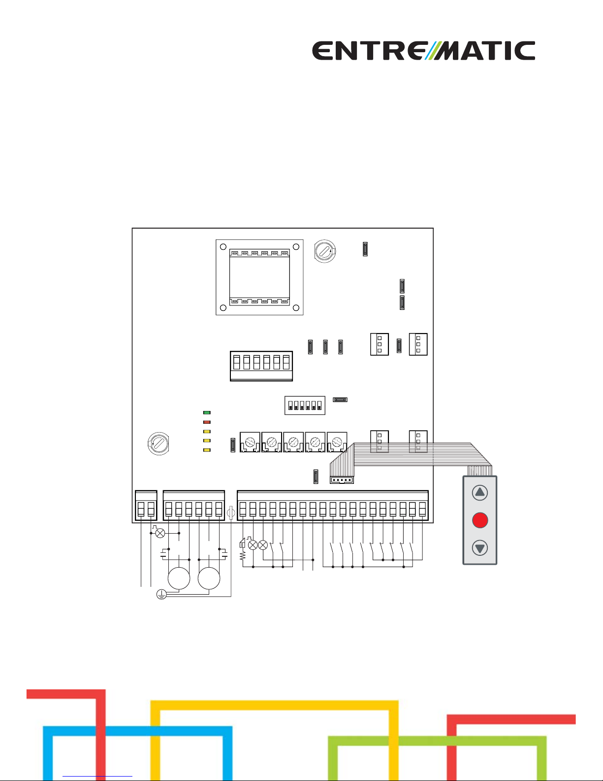
AUX
AUX
JR6
POWER
SA
IN
11
12
F1
F2
TC RP TR R1
OM
J7
15141312110011234567892041UWV X Z YLN
LN
com
com
Electric lock
Power suuply
Flashing light
Lamp
Limit switch
Limit switch
Accessories output
Automatic closing
Opening
Closing
Step by step
Opening safety device
Closing safety device
Safety reopening
Stop
Partial opening
Safety test
M1
1~
M2
1~
D5 S5 JT
NIO
SO
JR10
JR4
EO
1ON23456
F
U
S
E
F
U
S
E
LOGICM
RF
CT12345

24
IP1854EN - 2015-04-17

25
IP1854EN - 2015-04-17
Index
Subject Page
1. General safety precautions 26
2. EC declaration of conformity 27
3. Technical data 27
3.1 Applications 27
4. Commands 28
4.1 Self-controlled safety edge 29
5. Outputs and accessories 29
6. Adjustments 31
6.1 Trimmer 31
6.2 Dip-switch 31
6.3 Jumper 32
6.4 Signals 32
7. Start-up 33
8. Troubleshooting 34
9. Example application for two-motors swing gates 35
10. Example application for one-motor swing gate 37
11. Example application for sliding gate 39
12. Example application for barrier 39
13. Example of parallel 40
Caption
i
This symbol indicates informations which are useful for correct product function.
This symbol indicates instructions or notes regarding safety issues which require par ticular attention.

26
IP1854EN - 2015-04-17
1. General safety precautions
This installation manual is intended for qualified personnel only.
Installation, electrical connections and adjustments must be performed in accordance
with Good Working Methods and in compliance with applicable regulations.
Before installing the product, carefully read the instructions. Bad installation could be hazardous.
The packaging materials (plastic, polystyrene, etc.) should not be discarded in the environ-
ment or left within reach of children, as these are a potential source of hazard.
Before installing the product, make sure it is in perfect condition.
Do not install the product in an explosive environment and atmosphere: gas or inflammable
fumes are a serious hazard risk.
Before installing the motors, make all structural changes relating to safety clearances and
protection or segregation of all areas where there is risk of being crushed, cut or dragged, and
danger areas in general.
Make sure the existing structure is up to standard in terms of strength and stability. The motor
manufacturer is not responsible for failure to use Good Working Methods in building the frames
to be motorized or for any deformation occurring during use.
The safety devices (photocells, safety edges, emergency stops, etc.) must be installed taking
into account: applicable laws and directives, Good Working Methods, installation premises,
system operating logic and the forces developed by the motorized door.
The safety devices must protect any areas where the risk exists of being crushed, cut or gragged,
or where there are any other risks generated by the motorized door.
Apply hazard area notices required by applicable regulations.
Each installation must clearly show the identification details of the motorized door.
When necessary, connect the motorized door to a reliable earth system made in accordance
with applicable safety regulations.
During installation, maintenance and repair, interrupt the power supply before opening the lid
to access the electrical parts.
The protective casing of the automation must be removed by qualified personnel only.
To handle electronic parts, wear earthed antistatic conductive bracelets. The motor manu-
facturer declines all responsibility in the event of component parts being fitted that are not
compatible with the safe an correct operation.
For repairs or replacements of products only original spare parts must be used. The installer
shall provide all information relating to automatic, manual and emergency operation of the
motorized door, and provide the user with operating instructions.
27
IP1854EN - 2015-04-17
The manufacturer Entrematic Group AB with headquarters in Lodjursgatan 10, SE-261 44
Landskrona, Sweden
declares that the control panel Ditec LOGICM is in conformity with the provisions of the following
EC directives:
EMC Directive 2004/108/CE;
Low Voltage Directive 2006/95/CE.
Landskrona, 29-01-2013 Marco Pietro Zini
(President & CEO)
2. EC Declaration of conformity
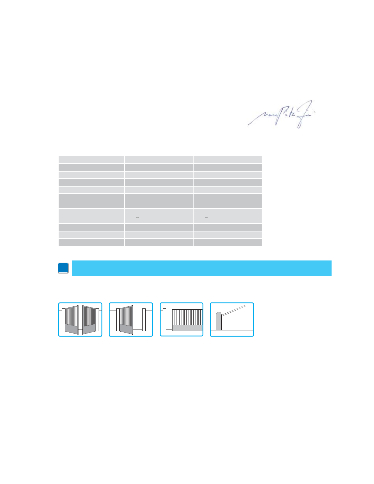
3. Technical data
LOGICM LOGICMJ
Power supply 230 V~ 50/60 Hz 120 V~ 60 Hz
F1 fuse F6,3A F6,3A
F2 fuse F3,15A F3,15A
One motor output 230 V~ 5A max 120 V~ 6,3A max
Two motor output
230 V~
2x2,5A max
120 V~
2x3,15A max
Accessories power
supply
24 V
0,5 A 24 V 0,5 A
Temperature min -20 °C max +55 °C min -20 °C max +55 °C
Degree of protection IP55 IP55
Dimensions 187X261X105 187X261X105
3.1 Applications
i
NOTE: the given operating and performance features can only be guaranteed with the use of DITEC
accessories and safety devices.
28
IP1854EN - 2015-04-17
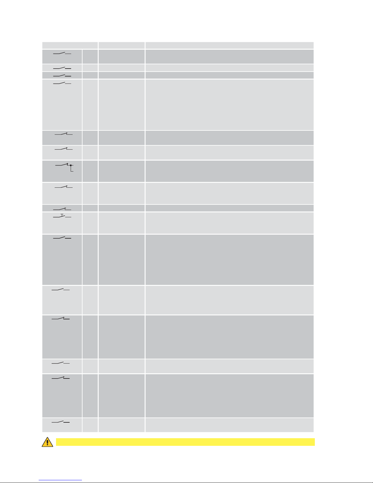
4. Commands
Command Function Description
1
2 N.O. AUTOMATIC
CLOSING
Permanently closing the contact enables automatic closing.
1
3 N.O. OPENING The opening operation starts when the contact is closed.
1
4 N.O. CLOSING The closing operation starts when the contact is closed.
1
5 N.O. STEP-BY-STEP With D5=ON closing the contact starts a sequential opening or clo-
sing operation: open-stop-close-open.
With D5=OFF closing the contact starts a sequential opening or closing operation: open-stop-close-stop-open.
Note: if automatic closing is enabled, with S5=ON the stop is not
permanent but at a time that is set by the TC, with S5=OFF the stop
is permanent.
41
6 N.C. OPENING SAFETY
DEVICE
Opening the safety contact stops the current opening operation in
progress and impedes any future opening operations.
41
7 N.C. CLOSING SAFETY
DEVICE
Opening the safety contact stops the current closing operation in
progress and impedes any future closing operations.
41
6
7
N.C. SAFETY STOP Opening the safety contact stops and prevents any movement.
Note: it does not carry out the disengagement operation. Use with
photocells installed only.
41
8 N.C. REVERSAL
SAFETY
DEVICE
Opening the safety contact triggers a reversal of motion (re-opening)
during a closing operation.
1
9 N.C. STOP Opening the safety contact stops the current operation.
1 9 N.C. EMERGENCY
STOP
To enable the emergency stop function (e.g. with a specific red button), connect the opening and closing controls to terminal 9 instead
of 1 (9-3, 9-4, 9-20).
1
9 N.O. HOLD-TO-RUN
FUNCTION
Permanently opening the safety contact enables the operator presence dependent function.
In this state, the opening (1-3, 1-20) and closing (1-4) controls function only if held in the pressed position and the automation stops
when the controls are released.
All safety switches, the step-by-step control and the automatic closing function are disabled.
1
20 PARTIAL
OPENING
Closing the contact activates a partial opening operation of the door
wing powered by motor 1, of the duration set with the RP trimmer.
Once the automation stops, the partial opening control performs the
opposite operation to the one performed before stoppage.
0 11 N.C. M2 LIMIT SWITCH With TC=MAX, the limit switch contact opening stops closing move-
ment of motor 2 (M2).
With OM=OFF (1 motor mode) and DIP2=OFF, the limit switch stops
closing movement of motor 1 (M1).
With OM=OFF (1 motor mode) and DIP2=ON, the limit switch stops
opening movement of motor 1 (M1).
0
11 N.O. M2 PROXIMITY
LIMIT SWITCH
See Chapters 9-10, example 4.
0
12 N.C. M1 LIMIT SWITCH With TC=MAX, the limit switch contact opening stops closing move-
ment of motor 1 (M1).
With OM=OFF (1 motor mode) and DIP2=OFF, the limit switch stops
opening movement of motor 1 (M1).
With OM=OFF (1 motor mode) and DIP2=ON, the limit switch stops
closing movement of motor 1 (M1).
0
12 N.O. M1 PROXIMITY
LIMIT SWITCH
See Chapters 9-10, example 4.
WARNING: Make a jumper on all N.C. contacts if not in use. The terminals with the same number are equal.
 Loading...