

Entrematic Ditec ION4, Ditec ION6, Ditec ION4J, Ditec ION6J Technical Manual
Ditec ION4-ION6
Sliding gates
(translation of the original instructions)
www.entrematic.com
IP2288EN • 2019-04-10
Technical Manual

Contents
1. General safety precautions 3
General safety precautions for the user 4
2. Declaration of incorporation of partly completed machinery 5
2.1 Machinery Directive 5
3. Technical specifications 6
4. Standard installation 7
5. Dimensions 8
6. Main components 8
7. Installation 9
7.1 Preliminary checks 9
7.2 Base plate position 9
7.3 Gearmotor installation 10
7.4 Rack installation
7.5 Operation with virtual encoder 12
7.6 Installation of optional accessories 12
7.6.1
Magnetic limit switches
7.6.2
Battery kit
7.6.3
Remote release handle
8. Electrical connections 13
9. LCU48 card 14
10. Using of the menus 15
10.1 Switching the display on and off 15
10.2 Navigation keys 15
10.3 Menu map 16
11. Product start-up 18
11.1 WZ configuration wizard menu 18
12. Commands 20
12.1
SOFA1-SOFA 2 or GOPAVRS self-controlled safety edge
13.
Outputs and accessories
14.
Jumper setting
15.
Adjustments
15.1
Main menu
15.2
Second level menu - AT (Automatic Configurations)
15.3
Second level menu - BC (Basic Configurations)
15.3.1
Additional BC level parameters that can be configured (available with AT → AA enabled)
15.4
Second level menu - BA (Basic Adjustment)
15.4.1
Additional BA level par ameters that can be configured (available with AT → AA enabled)
15.5
Second level menu - RO (Radio Operations)
15.5.1
Additional RO level par ameters that can be configured (available with AT → AA enabled)
15.6
Second level menu - SF (Special Functions)
15.6.1
Additional SF level parameters that can be configured (available with AT → AA enabled)
15.7
Second level menu - CC (Cycle Counter)
15.7.1
Additional CC level parameters that can be configured (available with AT → AA enabled)
15.8
Second level menu - EM (Energy Management)
15.8.1
Additional EM level parameters that can be configured (available with AT → AA enabled)
15.9
Second level menu - AP (Advanced Parameters)
15.9.1
Additional AP level parameters that can be configured (available with AT → AA enabled)
16.
Signals visualised on the display
16.1
Display of automation status
16.2
Display of safety devices and commands
16.3
Display of alarms and faults
17.
Troubleshooting
Subject Page
11
12
12
12
21
21
22
23
23
24
25
26
27
28
30
31
32
33
34
35
35
36
36
38
40
40
42
43
46
IP2288EN
EN
2
1. General safety precautions
Please follow these instructions. Failure to observe the information given in
this manual may lead to personal injury or damage to the equipment.
Keep these instructions for future reference.
This installation manual is intended for qualified personnel only.
Installation, electrical connections and adjustments must be performed by qualified personnel, in accordance with Good Working Methods and in compliance with the current regulations.
Read the instructions carefully before installing the product.
Bad installation could be dangerous.
This manual and those for any accessories can be downloaded from www.entrematic.com.
The packaging materials (plastic, polystyrene, etc.) should not be discarded in the environ-
ment or left within reach of children, as they are a potential source of danger.
Before installing the product, make sure it is in perfect condition.
Do not install the product in explosive areas and atmospheres: the presence of inflammable
gas or fumes represents a serious safety hazard.
Before installing the motorisation device, make all the necessary structural modifications to
create safety clearance and to guard or isolate all the crushing, shearing, trapping and general
hazardous areas.
Make sure the existing structure is up to standard in terms of strength and stability. The motorisation device manufacturer is not responsible for failure to observe Good Working Methods
when building the frames to be motorised, or for any deformation during use.
The safety devices (photocells, safety edges, emergency stops, etc.) must be installed taking into
account: applicable laws and directives, Good Working Methods, installation premises, system
operating logic and the forces developed by the motorised door or gate.
The safety devices must protect against crushing, cutting, trapping and general danger areas
of the motorised door or gate.
Display the signs required by law to identify hazardous areas.
Each installation must bear a visible indication of the data identifying the motorised door or gate.
When nece ssar y, connec t the motor ised door or gate to an effective earthing system that complies with the current safety standards.
During installation, maintenance and repair operations, cut off the power supply before
opening the cover to access the electrical parts.
The automation protection casing must be removed by qualified personnel only.
The electronic parts must be handled using earthed antistatic conductive arms. The manu-
facturer of the motorisation declines all responsibility if component parts not compatible
with safe and correct operation are fitted.
Only use original spare parts for repairing or replacing products.
The installer must supply all information concerning the automatic, manual and emergency operation of the motorised door or gate, and must provide the user with the operating instructions.
The installer must ensure that the temperature range indicated in the technical specifications
is compatible with where the gate will be used.
IP2288EN
3
EN

General safety precautions for the user
These precautions are an integral and essential part of the product
and must be supplied to the user.
Read them carefully since they contain important information on safe
installation, use and maintenance.
These instructions must be kept and forwarded to all possible future
users of the system.
This product must only be used for the specific purpose for which it
was designed.
Any other use is to be considered improper and therefore dangerous.
The manufacturer cannot be held responsible for any damage caused
by improper, incorrect or unreasonable use.
Avoid operating in the proximity of the hinges or moving mechanical
parts. Do not enter within the operating range of the motorised door
or gate while it is moving.
Do not obstruct the motion of the motorised door or gate, as this may
cause a dangerous situation.
The motorised door or gate may be used by children over the age of 8
and by people with reduced physical, sensorial or mental abilities, or
lack of experience or knowle dge, as long as they are properly super vised
or have been instructed in the safe use of the device and the relative
hazards.
Children must be supervised to make sure they do not play with the
device, nor play/remain in the sphere of action of the motorised door
or gate.
Keep remote controls and/or any other command devices out of the
reach of children, to avoid any accidental activation of the motorised
door or gate.
In the event of a product fault or malfunction, turn off the power supply
switch. Do not attempt to repair or intervene directly, and contact only
qualified personnel.
Failure to comply with the above may cause a dangerous situation.
Any repair or technical intervention must be carried out by qualified
personnel.
Cleaning and maintenance work must not be carried out by children
unless they are supervised.
To ensure that the system works efficiently and correctly, the manufacturer’s indications must be complied with and only qualified personnel
must perform routine maintenance on the motorised door or gate. In
particular, regular checks are recommended in order to verify that the
safety devices are operating correctly.
All installation, maintenance and repair work must be documented and
IP2288EN
EN
4

made available to the user.
Only lock and release the door wings when the motor is switched off.
Do not enter within the operating range of the wing.
To dispose of electrical and electronic equipment correctly, users
must take the product to special "recycling centres" provided by
the municipal authorities.
2. Declaration of incorporation of partly completed machinery
(Directive 2006/42/EC, Annex II-B)
The manufacturer Entrematic Group AB, with headquarters in Lodjursgatan 10, SE-261 44 Landskrona, Sweden, declares that the Ditec ION4-ION6 automation for swing gates:
- is designed to be installed on a manual gate to form a machine pursuant to Directive 2006/42/
EC. The manufacturer of the motorised gate must declare conformity with Directive 2006/42/
EC (annex II-A) prior to initial machine start-up;
- complies with the applicable essential safety requirements indicated in Annex I, Chapter 1 of
the Directive 2006/42/EC;
- complies with the RED Directive 2014/53/EU;
- the safety functions are compliant with Category 2, PLc according to EN ISO 13849-1;
- the technical documentation complies with Annex VII-B of the Directive 2006/42/EC;
- the technical documentation is managed by the Technical Office of Entrematic Italy (with
headquarters in Largo U. Boccioni 1 – 21040 Origgio (VA) – ITALY) and is available upon request,
sending an e-mail to ditec@entrematic.com ;
- a copy of the technical documentation will be given to competent national authorities, following
a suitably justified request.
Landskrona, 26-02-2018 Matteo Fino
(Chairman)
2.1 Machinery Directive
Pursuant to Machinery Directive (2006/42/EC) the installer who motorises a door or gate has the
same obligations as the manufacturer of machinery and as such must:
- prepare the technical data sheet which must contain the documents indicated in Annex V of the
Machinery Directive;
(The technical data sheet must be kept and placed at the disposal of competent national authori-
ties for at least ten years from the date of manufacture of the motorised door or gate);
- draw up the EC Declaration of Conformity in accordance with Annex II-A of the Machinery Direc-
tive and deliver it to the customer;
- affix the EC marking on the motorised door or gate, in accordance with point 1.7.3 of Annex I of
the Machinery Directive;
- ensure compliance of the motorised door or gate with safety regulations, by installing the neces-
sary safety devices;
IP2288EN
5
EN
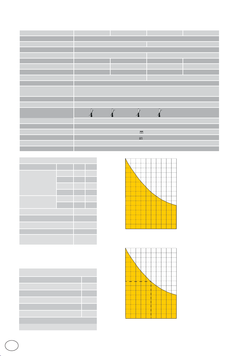
3. Technical specifications
Maximum stroke 12m
Maximum gate weight 400Kg 600Kg
Gate speed 0,1÷0,3 m/s
Thrust 200N nominal, 600N start-up 300N nominal, 800N start-up
Power supply 230 V~ 50/60Hz 120 V~ 50/60Hz 230 V~ 50/60Hz 120 V~ 50/60Hz
Power absorption 0,45A 0,9A 0,6A 1,2A
Fuse T1A F2A F1,6A F3,15A
Power 100 W 130 W
Intermittence 80 cycles/day, 30 continuous cycles
Lifespan
Acoustic pressure LpA ≤ 70dB(A)
IP degree of protection 44
Usage temperature
Product size 300 x 260 x 195
Control panel LCU48
Motor output 24V
Power supply to accessories 24V
Radio frequency 433,92 MHz
Storable radio codes 100 / 200 vedi RO → MU → 20/10
Index of conditioning factors
>150Kg 10 -
Gate wing weight
>200Kg 20 10
>300Kg 30 20
>400Kg - 30
Gate wing width
>4m 20 10
>8m - 20
Wheel diameter <100mm 10
Saline environment 10
Safety edge installed 10
R1/R2 > default 10
VA/VC > default
OC/CB < default
Example of lifespan calculation for ION4
Gate wing weight>150Kg 10
Gate wing width> 4.5m 10
Dust 10
Safety edges installed 10
VA/VC > default 10
Total stress index 50
Estimated lifespan - 80,000 cycles
Estimated daily cycles 22 (for 10 years)
ION4 ION4J ION6 ION6J
From 50,000 to 150,000 cycles, depending on the conditions indicated in table
(see the product lifespan charts)
-20°C +55°C ( -35°C +55°C with active NIO)
10A max
0,3A max
150.000
ION4 ION6
10
140.000
130.000
120.000
110.000
100.000
90.000
80.000
cicli
70.000
cycles
60.000
50.000
40.000
30.000
20.000
10.000
0
0
102030
indice di gravosità
Index of conditioning factors
150.000
140.000
130.000
120.000
110.000
100.000
90.000
80.000
cicli
70.000
cycles
60.000
50.000
40.000
30.000
20.000
10.000
0
0
102030
Index of conditioning factors
indice di gravosità
405060
405060
90
70
80
100
90
70
80
100
IP2288EN
EN
6
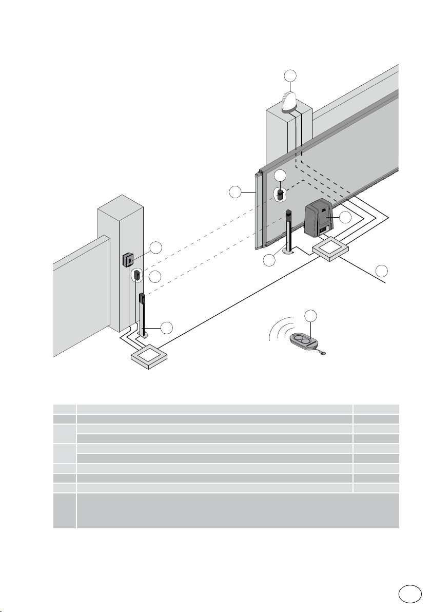
4. Standard installation
3
4
4
2
4
6
5
4
A
1
Rif. Description Cable
1 Remote control /
Flashing light 2 x 1 mm²
2
Antenna (integrated into the flashing light) coaxial 58 Ω
Key selector switch 4 x 0,5mm²
3
Digital combination wireless keypad /
4 Photocells 4 x 0,5 mm²
5 Actuator ION with control panel 3G x 1,5 mm²
6 Safety edge 2 x 0,5 mm²
Connect the power supply to a type-approved omnipolar switch, with a contact opening distance of at
least 3mm (not supplied).
A
The connection to the mains must follow an independent path, separate from the connections to the
control and safety devices.
IP2288EN
7
EN
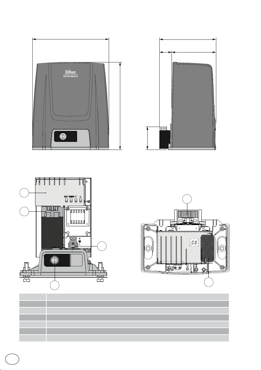
5. Dimensions
260
6. Main components
9
8
195
15540
300
80
11
EN
12
10
Rif. Descrizione
8 Motor
9 Control panel
10 Key release
11 Pinion
12 Cable inlet
13 Power supply terminal and fuse
8
12
IP2288EN

7. Installation
The given operating and performance features can only be guaranteed with the use of DITEC ac-
cessories and safety devices.
Unless otherwise specified, all measurements are expressed in mm.
7.1 Preliminary checks
Check the stability of the wing (derailing and lateral falls) and the sliding wheels and that the upper
guides do not cause any friction.
The sliding guide must be securely fixed to the ground for the full length within doorway and must
have no irregularities that could hinder the movement of the wing.
The opening and closing stops must be fitted.
If the gate has slits, make sure they are covered to prevent shearing points or install active safety
edges on the columns.
Safety device should be installed at the end of the wing to reduce the collision force.
NB:
•Make sure that the gate can not exit the sliding guides and fall.
•Make sure that the protection system and any manual release function correctly.
7.2 Base plate position
Make a concrete base with the anchor ties and base plate embedded, which must be level and
clean and of the size indicated in the figure.
NB: if the concrete base has already been made, base plate can be fixed using M8 plugs
i
(not supplied).
IP2288EN
[*] CROSSCRI
[*] CROSSCRN2
X=40
X+20 [*]
160
OPENING
220
260
9
Ø80
40
min
90°
M12
low type
EN
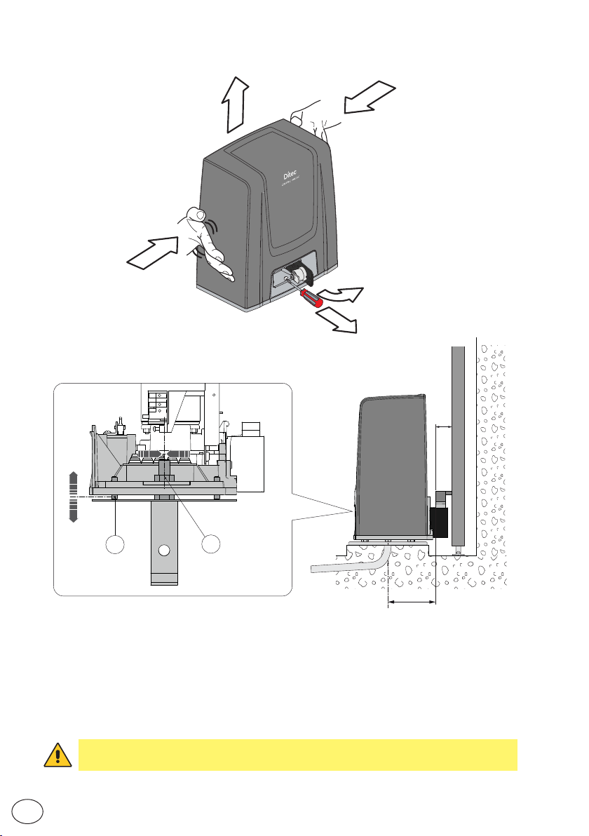
7.3 Gearmotor installation
4
3
3
1
2
X
-5 +20
±5
A
- Release the gearmotor [1] (see OPERATING INSTRUCTIONS). Loosen the front screw [2] and
remove the casing by pressing on its sides [3-4].
- Place the gearmotor on the base plate.
- Adjust the gearmotor horizontally by sliding it along the slots of the gearmotor base and vertically with
four levelling screws [A].
NB: during the vertical adjustment, keep the gearmotor slightly raised from the base plate so
that the rack can be fixed and subsequent adjustments are possible.
- After adjusting, fix the gearmotor using screws [B].
WARNING: The gearmotor must be suitably raised from the ground to avoid flooding.
Tighten the [B] screws using a tightening torque of 20-25 Nm.
B
100
10
EN
IP2288EN
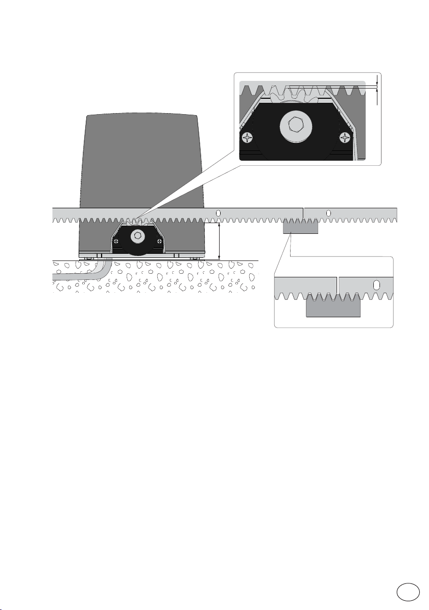
7.4 Rack installation
2÷3
min.80
- Release the gearmotor (see OPERATING INSTRUCTIONS) and open the gate.
- Place the rack against the pinion and sliding the gate manually fix it along its whole length.
NB: To make it easier to align the rods correctly, use a scrap piece of rack and rest it underneath
the junction point, as shown in the figure detail.
- Once fixed, vertically adjust the gearmotor to give a play of about 2 to 3 mm between the pinion
and the rack.
- Secure the gearmotor with the [B] screws using a tightening torque of 20-25 Nm.
- Slightly lubricate the rack and pinion after assembly.
Manually check that the gate slides evenly and without friction.
IP2288EN
11
EN
7.5 Operation with virtual encoder
ION4-ION6 gearmotors do not require limit switches because they have a virtual encoder.
Mechanical opening and closing end stops must be installed.
The gate automatically slows when approaching the end stops.
WARNING: when the gate reaches the opening or closing limit stop, it reverses briefly to facilitate
manual release of the gearmotor.
7.6 Installation of optional accessories
7.6.1 Magnetic limit switches
The limit switch kit is used to stop the gate before it reaches the opening and closing
mechanical stops.
i
With a limit switch installed, slowdown is carried out at regulated power to overcome
possible friction.
For the installation of the limit switch kit, refer to the NES100FCM manual.
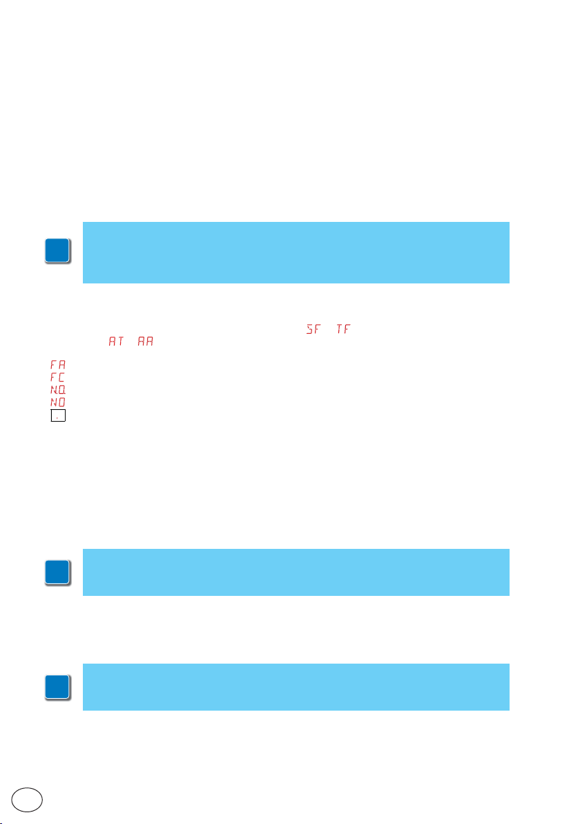
To position the limit switches, you can use the menu
configurations
The display shows the status of the limit switches:
•
: opening limit switch configured and activated;
•
: closing limit switch configured and activated;
•
(both parts of display active): opening limit switch not configured and activated;
•
(no par t of display active): closing limit s witch not configured and activated;
•
(central part of display active): no limit s witch activated;
With the limit switches configured as STOP (FA = SX; FC = SX) the anti-violation function is activated. When
the auto mation stopped open or closed, if the gate ba cks off rel easing the limit swi tch, it is brou ght back into
position avoiding openings from external forces [energy saving must be disabled ES = OFF].
→ ).
→ (visible by activating the additional
7.6.2 Battery kit
For installation of the battery kit, refer to the SBU-IONSBU-BBU20-BBU65 (IP2254) manual.
The battery kit guarantees operation if there is a power cut.
For advanced control of battery-powered operation, refer to the
i
EM menu.
7.6.3 Remote release handle
For installation of the remote release handle, refer to the IONSBM and ASR2 manual.
The kit can be used to remotely release the gearmotor.
A microswitch guarantees safety.
i
When the handle is released, the control panel performs a reset
EN
IP2288EN
12

8. Electrical connections
B
A
B
A
Before connecting the power supply, make sure the plate data correspond to that of the
mains power supply.
An omnipolar disconnection switch with a contact opening distance of at least 3mm must be
fitted on the mains supply.
Check there is an adequate residual current circuit breaker and overcurrent cutout upstream
of the electrical system.
For the po wer supply, use a H0 5RN-F 3G1.5 type electric cable. Connect it to terminals L (brown),
N (blue), (yellow/green) inside the automation.
NOTE: the maximum permisible section of the wire is AWG14 (2 mm2).
In order to comply with essential requirements of standards in force, reclose the cover once
the wires have been connected to the terminal.
In the external automation section, the connections to the mains power supply and any other low
voltage wires (230V) must be made on an independent channel separated from the connections
to the command and safety devices (SELV = Safety Extra Low Voltage).
The channel must penetrate the automation through the holes on the base plate by a few centimetres.
Make sure there are no sharp edges that may damage the power supply cable.
Make sure the mains power wires (230V) and the accessor y wires (24V) are separated. The cables
must be double insulated. Unsheathe them in line with the relative connection terminals, and
use cable fasteners (see ref. A) or straps (not supplied by us) to hold them in place.
IP2288EN
13
EN
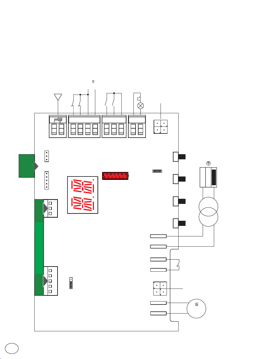
9. LCU48 card
Antenna
Sicurezza in chiusura
Closing safety device
Antenna
Arresto di sicurezza
Safety stop
+
-
24V output
Uscita 24 V
Apertura parziale
Partial opening
Passo-passo
Step-by-step
Lampeggiante
Flashing light
kit
SBU
SBU battery
Kit batteria
6ZENRS
ZENPRS
PLUG-IN BOARD
SCHEDA AD INNESTO
8
016
30
520
+-LP
BAT
Power supply
UPDOWN
C
O
RDX
M
JR1
ENTERESC
Alimentazione
LN
Fuse
Fusibile
Transformer
Trasformatore
24V~
AUX
Microswitch
SSW
Release
microswitch
di sblocco
LSW
JR5
130
Limit switch
Finecorsa
NES100FCM
NES100FCM
EN
14
M+ M-
24V
Motor
Motore
IP2288EN

10. Using of the menus
NB: pressure on the keys may be quick (less than 2 s) or prolonged (longer than 2 s).
Unless specified otherwise, quick pressure is intended.
i
To confirm the setting of a parameter, prolonged pressing is necessar y.
10.1 Switching the display ON and OFF
The procedure to switch on the display is as follows:
• press the ENTER key
• the display functioning check starts
• the first level menu is displayed
The procedure to switch off the display is as follows:
• press the ESC key
NB: there is no automatic exit from the WZ quick configuration menu. For all the other menus,
the display switches off automatically after 60 seconds of inactivity.
10.2 Navigation keys
• The simultaneous pressing of the ↑ and ENTER keys produces an opening command.
• The simultaneous pressing of the ↓and ENTER keys produces a closing command.
• The simultaneous pressing of the ↑ and ↓ keys produces a POWER RESET command (power supply interruption and automation restart).
• Keep the UP ↑ or DOWN ↓ key pressed to begin fast menu scrolling.
To set a parameter, select the desired value and press ENTER for 2 seconds to save.
Example: setting of 30 seconds for parameter TC
x 2 s
• In some menus, the parameter measurement unit can be viewed by pressing the ENTER key
once the value has been displayed.
IP2288EN
15
EN
 Loading...