

Entrematic Ditec EL34 Installation Manual
www.ditecentrematic.com
IP2152EN
Ditec EL34
Control panel installation manual for QIK80EH barrier
(Original instructions)
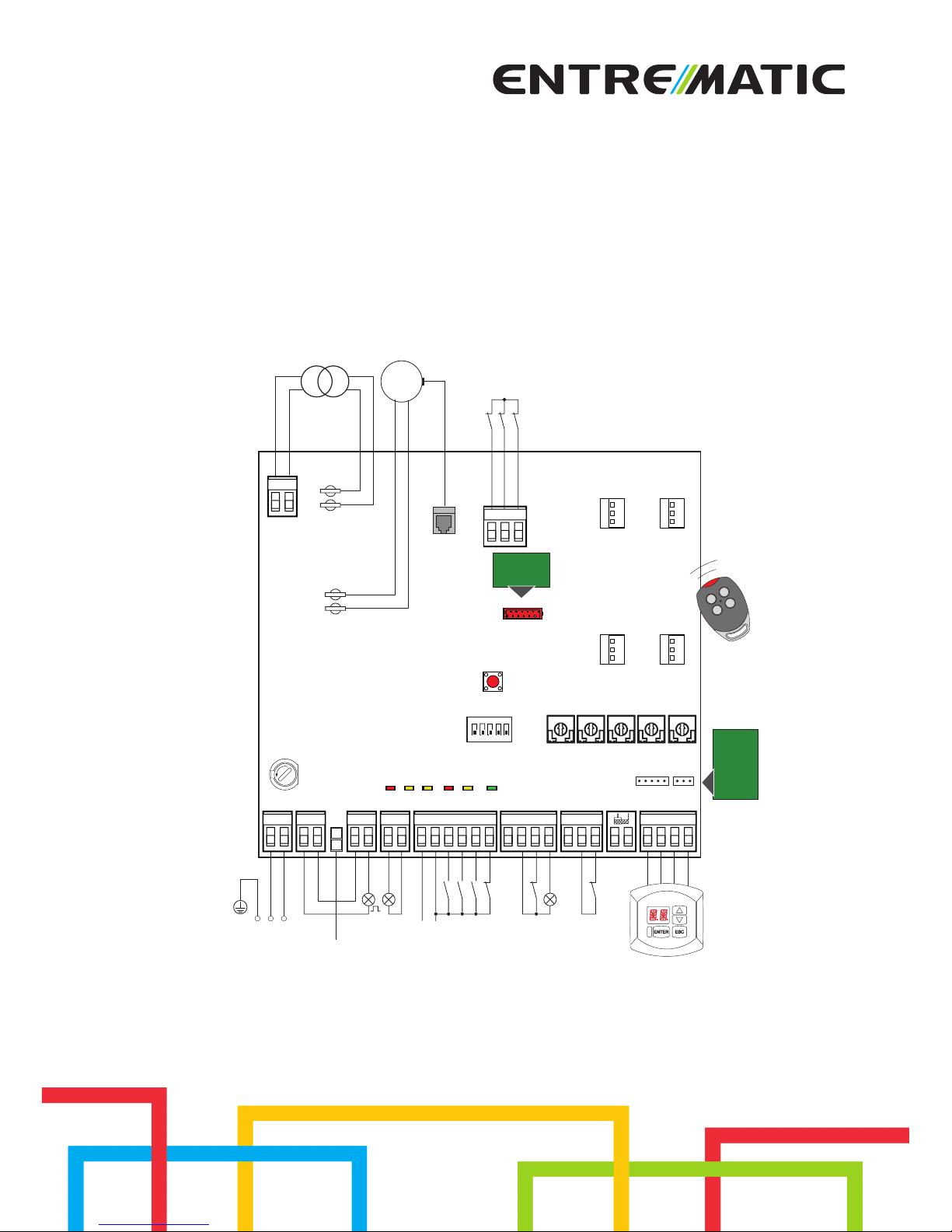
Safety reopening
Safety reopening
Automation status lamp
-
+
Output 24 V= / max 0,5 A
Power supply
BATKH
Flashing light
Lighting kit
Automatic closing
Opening
Closing
Stop
RDX
MD2
GOLR
POWER
ALARMSA11 IN12
VA VC TC R1 CB
AUX
24V~
012349 01G1 G3 0121 22018CNO
TRF
LN 14 0
PRG
COM
ENC
AUX
1ON2345
EL34
SIG
Transformer
24V=
Motor
BAT +G2-
1112 0
F1
F
U
S
E
BIXMR2
Limit switch
Limit switch
Safety switch
GOL4
+
M
-
20
IP2152EN - 2015-03-16
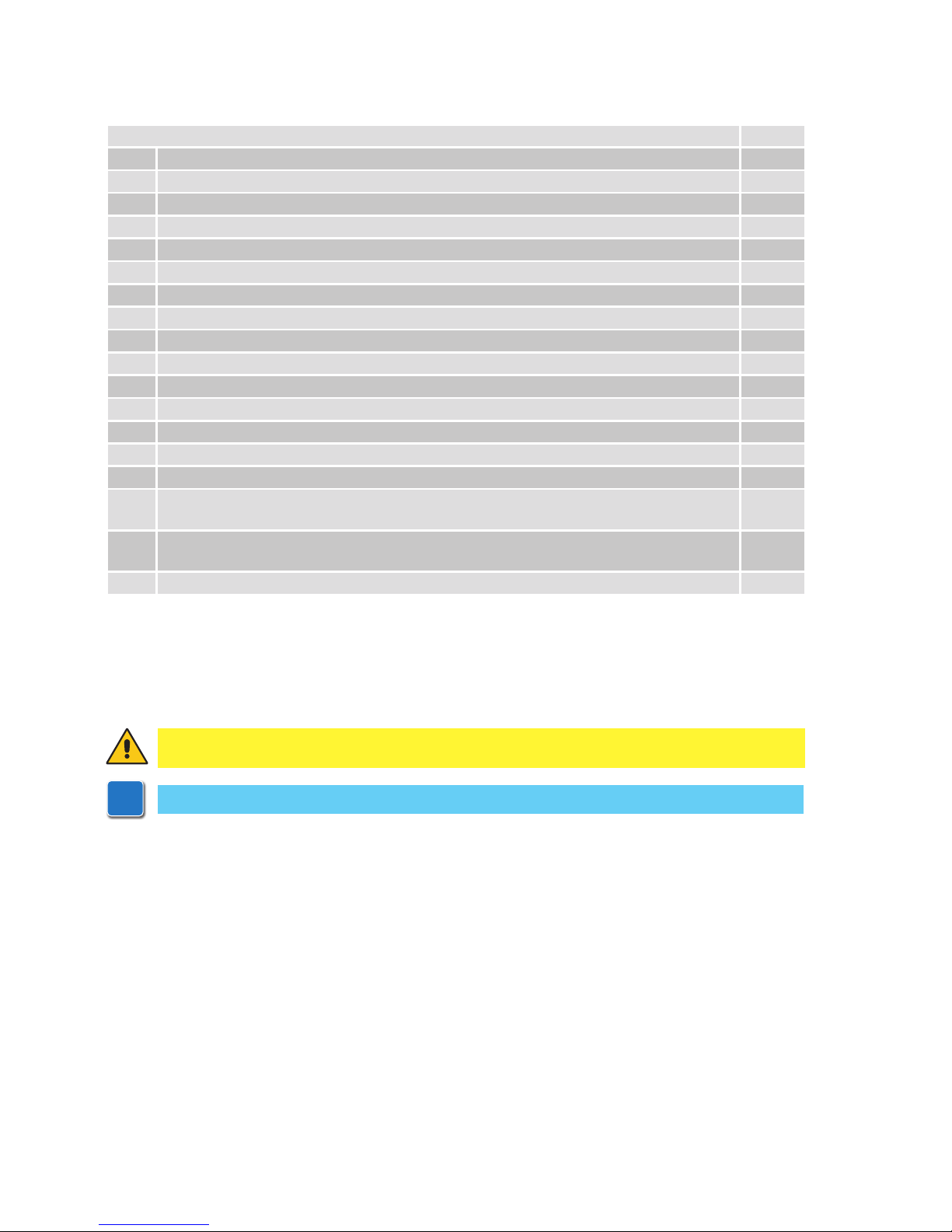
Index
Subject Page
1. General safety precautions 21
2.
EC declaration of conformity 22
3. Technical specifications 22
3.1
Applications 22
4. Commands 23
5. Outputs and accessories 24
6. Settings 25
6.1 Trimmers 25
6.2 Dip-switches
26
6.3 Jumper 26
6.4 Signals 26
7. Radio 27
8. Start-up 28
9. Troubleshooting 29
10. Example of application for parallel automations 30
11. Example of application for automations with two-way interlocking device without presence detection
31
12. Example of application for automations with two-way interlocking device with presence
detection
32
13. Example of application for automations with two-way operating mode 33
Key
All the rights concerning this material are the exclusive property of Entrematic Group AB. Although the contents of this publication have been drawn up with the greatest care, Entrematic Group AB cannot be held
responsible in any way for any damage caused by mistakes or omissions in this publication.
We reserve the right to make changes without prior notice. Copying, scanning and changing in any way are
expressly forbidden unless authorised in writing by Entrematic Group AB.
i
This symbol indicates useful information for the correct functioning of the product.
This symbol indicates instructions or notes regarding safety, to which special attention must be paid.
21
IP2152EN - 2015-03-16
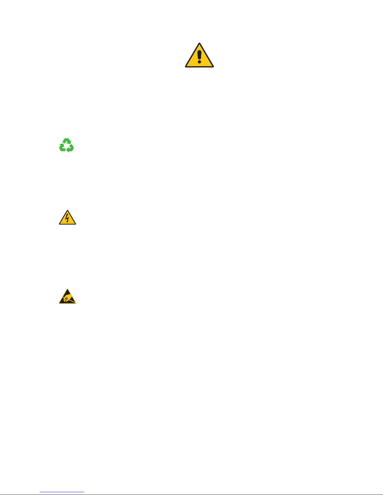
This installation manual is intended for qualified personnel only.
Installation, electrical connections and adjustments must be performed in accordance
with Good Working Methods and in compliance with the present standards.
Read the instructions carefully before installing the product. Bad installation could
be dangerous.
The packaging materials (plastic, polystyrene, etc.) should not be discarded in
the environment or left within reach of children, as these are a potential source
of danger.
Before installing the product, make sure it is in perfect condition.
Do not install the product in explosive areas and atmospheres: the presence of inflammable gas or fumes represents a serious safety hazard.
The safety devices (photocells, safety edges, emergency stops, etc.) must be installed
taking into account: applicable laws and directives, Good Working Methods, installation premises, system operating logic and the forces developed by the automation.
Before connecting the power supply, make sure the plate data correspond to that
of the mains power supply. An omnipolar disconnection switch with minimum
contact gaps of 3 mm must be included in the mains supply.
Check that there is an adequate residual current circuit breaker and a suitable overcurrent cut-out upstream of the electrical installation in accordance with Good Working
Methods and with the laws in force.
When requested, connect the automation to an effective earthing system that complies
with current safety standards.
During installation, maintenance and repair operations, cut off the power supply before
opening the cover to access the electrical parts.
The electronic parts must be handled using earthed antistatic conductive arms.
The manufacturer of the motorisation declines all responsibility in the event
of component parts being fitted that are not compatible with the safe and correct
operation.
Use original spare parts only for repairing or replacing products.
1. General safety precautions
“Important instructions for installation safety.
Incorrect installation can cause serious injury”

22
IP2152EN - 2015-03-16
The manufacturer Entrematic Group AB, with headquarters in Lodjursgatan 10, SE-261 44 Landskrona, Sweden,
declares that the Ditec EL34 type control panel complies with the conditions of the following
EC directives:
EMC Directive 2004/108/EC
Low Voltage Directive 2006/95/EC
R&TTE Directive 1999/5/EC
Landskrona, 14-02-2013 Marco Pietro Zini
(President EA)
2. EC Declaration of Conformity
3. Technical specifications
QIK80EH
Power supply 230 V~ 50/60 Hz
F1 fuse F2A
Motor output 24 V 16 A
Accessories power supply 24 V 0.5 A
Temperature
min -20° C max +55° C
min -35° C max +55° C with NIO activated
min -10° C max +50° C with batteries
Degree of protection IP55
Radio frequency 433.92 MHz
Storable transmitters 200
3.1 Applications
i
NOTE: The given operating and performance features can only be guaranteed with the
use of DITEC accessories and safety devices.
23
IP2152EN - 2015-03-16
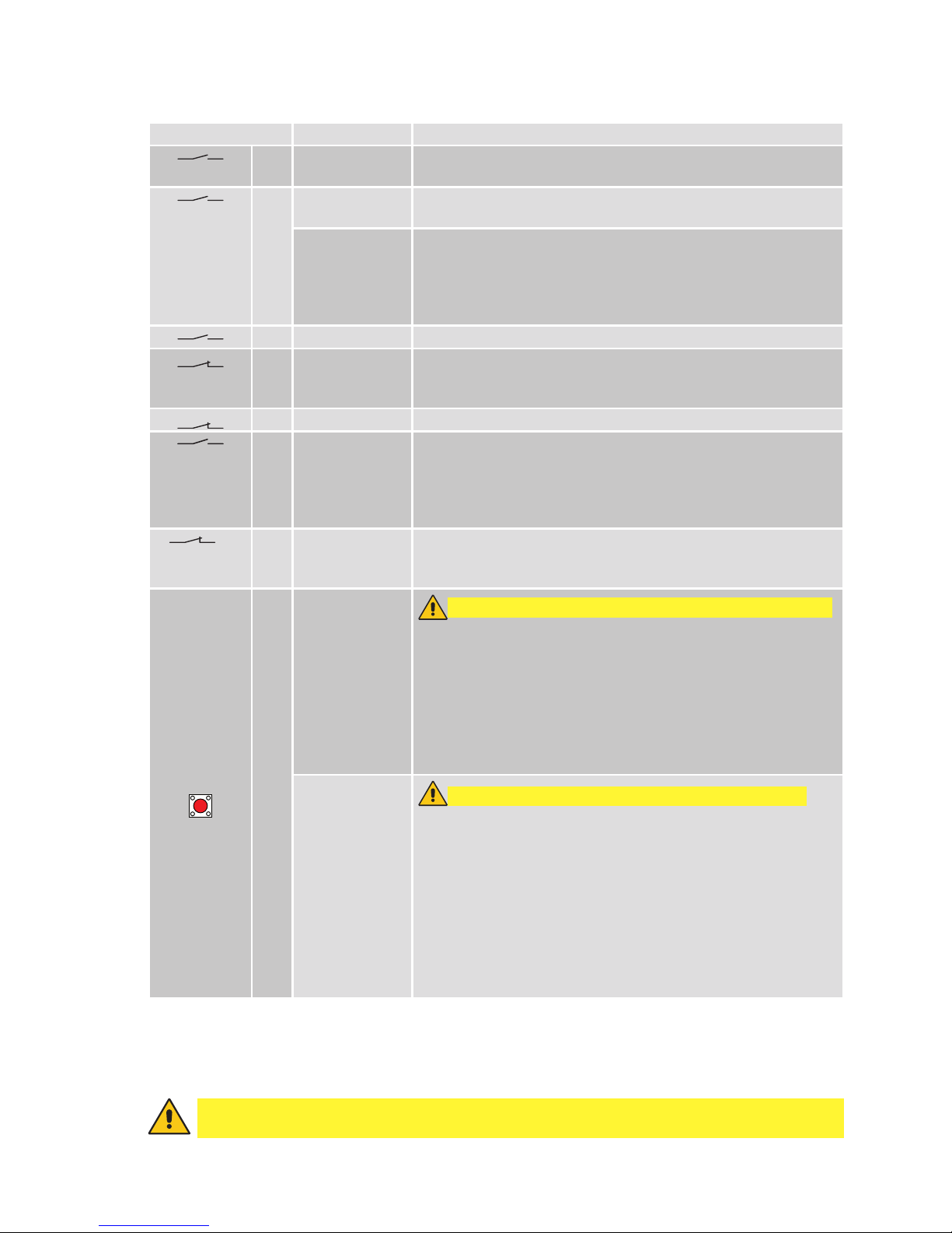
4. Commands
Command Function Description
1 2 N.O. AUTOMATIC
CLOSING
Permanently closing the contact enables automatic closing.
1 3
N.O. OPENING
With DIP1=ON, closing the contact activates an opening operation.
STEP-BY-STEP With DIP1=OFF, closing the contact activates an opening or clos-
ing operation in the following sequence: opening-stop-closingopening.
N.B.: if automatic closing is enabled, the stop is not permanent
but has a duration set with the TC trimmer.
1 4 N.O. CLOSING The closing operation starts when the contact is closed.
1 8 N.C. REVERSAL
SAFETY
CONTACT
Opening the safety contact triggers a reversal of the movement
(reopening) during the closing operation.
1 9 N.C. STOP Opening the safety contact stops the current operation.
1 9 N.O. OPERATOR
PRESENT
CONTROL
Opening of contact 1-9 enables the operator present function.
- opening with operator present 1-3 [with DIP1=ON];
- closing with operator present 1-4.
N.B.: any safety devices, automatic closing and plug-in cards in
the AUX1, AUX2 and RDX housings are disabled.
1 G1 N.C. REVERSAL
SAFETY
CONTACT
Opening the safety contact triggers a reversal of the movement
(reopening) during the closing operation.
PRG
N.O. TRANSMITTER
STORAGE AND
CANCELLATION
WARNING: the storage module MUST BE inser ted.
Transmitter storage:
- press the PRG key (the SIG LED turns on),
- proceed with transmission from the transmitter to be stored
(the SIG LED flashes),
- wait 10 s for storage to be completed (the SIG LED turns off).
Transmitter cancellation:
- press the PRG key for 3 s (the SIG LED flashes),
- press the PRG key again for 3 s (the SIG LED flashes faster).
SETTINGS
RESET
WARNING: the storage module must NOT be inserted.
- press the PRG key for 4 s (the IN LED flashes),
- press the PRG key within 4 sec for another 2 sec (the IN LED
comes on).
The SETTINGS RESE T deletes all the remote software settings
made using the MD2 display module. After SETTINGS RESET it
is possible to adjust the control panel directly.
WARNING: if the MD2 display module is disconnected from the
control panel, a SETTINGS RESET must be performed.
Warning: make a jumper for all NC contacts if not in use. The terminals with the same
number are equal.
 Loading...