

Entre Matic Ditec EL31R Installation Manual
Ditec EL31R
Installation Manual for control panel for 24V automations with
built-in radio.
www.ditecentrematic.com
IP1851EN
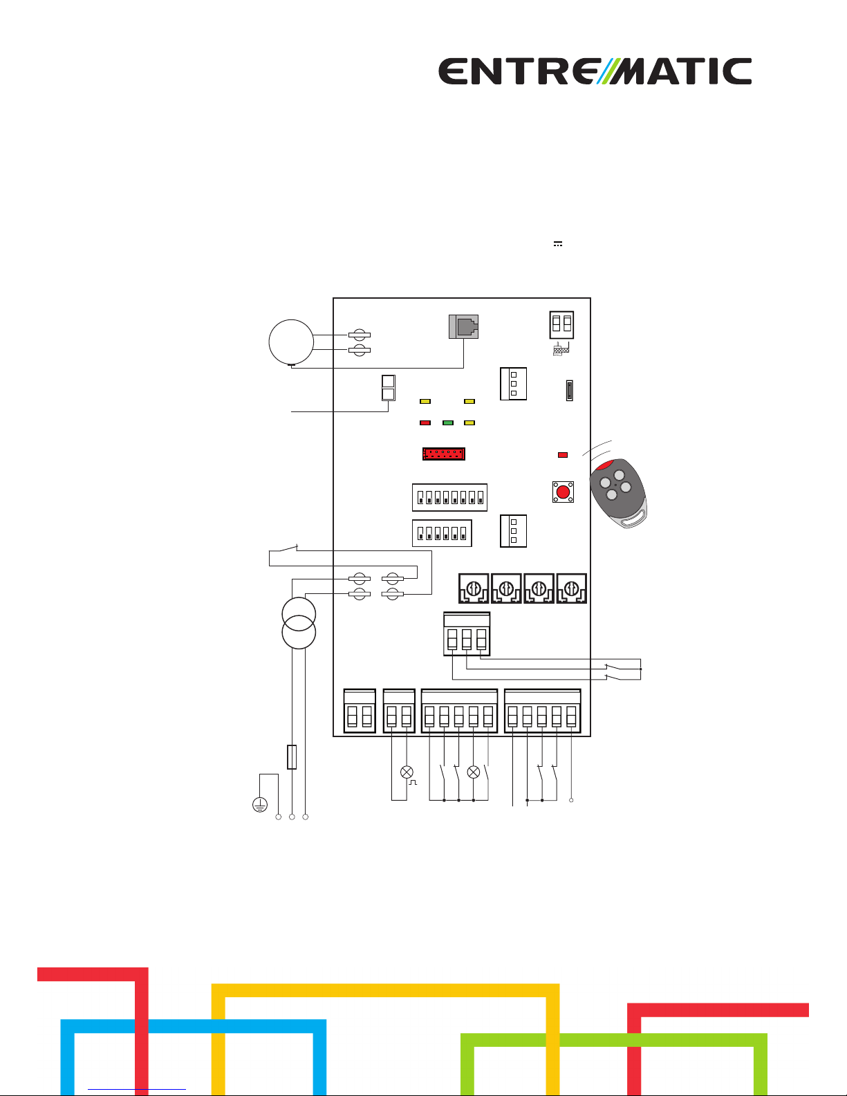
POWER
SA
11IN
Limit switch
Limit switch
Accessories output
12
VAAVC TC R1
AUX
A
N
T
B
A
T
SAFETY24V~
1591320 016841CNO
1112 0
14 0
PRG
COM
ENC
JR1
1ON23456
B
1ON23456 78
EL31R
SIG
-M
+M
Power supply
Step-by-step
Safety stop
Safety reopening
Stop
Safety test
Flashing light
Gate open indicator light
Partial opening
GOL4
F1
Transformer
Safety switch
24V=
Motor
BATK3

28
IP1851EN - 2014-09-30

29
IP1851EN - 2014-09-30
Index
Subject Page
1. General safety precautions 30
2. EC declaration of conformity 31
3. Technical specifications 31
3.1 Applications 31
4. Commands 32
4.1 Self-controlled safety edge 33
5. Sliding gates outputs and accessories 34
6. Barriers outputs and accessories 35
7. Settings 36
7.1 Trimmers 36
7.2 Sliding gates dip-switches 37
7.3 Barriers dip-switches 38
7.4 Jumper 39
7.5 Signals 39
8. Radio 40
9. Working modes for sliding gates 41
10. Start-up 42
10.1 Sliding gates start-up 42
10.2 Barriers start-up 43
11. Troubleshooting 44
12. Application example for sliding gates 46
13. Application example for barriers 47
14. Example of operator present function mode 47
15. Application example for parallel automations 48
Key
i
This symbol indicates useful information for the correct functioning of the product.
This symbol indicates instructions or notes regarding safety, to which special attention must be paid.

30
IP1851EN - 2014-09-30
1. General safety precautions
This installation manual is intended for qualified personnel only.
Installation, electrical connections and adjustments must be performed in accordance
with Good Working Methods and in compliance with the present standards.
Read the instructions carefully before installing the product.
Bad installation could be dangerous.
The packaging materials (plastic, polystyrene, etc.) should not be discarded in the environ-
ment or left within reach of children, as these are a potential source of danger.
Before installing the product, make sure it is in perfect condition.
Do not install the product in explosive areas and atmospheres: the presence of inflammable
gas or fumes represents a serious safety hazard.
The safety devices (photocells, safety edges, emergency stops, etc.) must be installed taking
into account: applicable laws and directives, Good Working Methods, installation premises,
system operating logic and the forces developed by the automation.
Before connecting the power supply, make sure the plate data correspond to that of the
mains power supply.
An omnipolar disconnection switch with minimum contact gaps of 3 mm must be included
in the mains supply.
Check that upstream of the electrical installation there is an adequate residual current circuit
breaker and a suitable overcurrent cutout.
When requested, connect the automation to an effective earthing system that complies with
current safety standards.
During installation, maintenance and repair operations, cut off the power supply before opening
the cover to access the electrical parts.
The electronic parts must be handled using earthed antistatic conductive arms.
The manufacturer of the motorisation declines all responsibility in the event of component
parts being fitted that are not compatible with the safe and correct operation.
Use original spare parts only for repairs or replacements of products.
1.1 Installation precautions
Fix the control panel permanently. Pass the cables along the lower side of the container.
If they are accessible, block the cables with cable glands (not supplied). Keep the line and motor
conductors separated from the command conductors by at least 8mm in the terminal boards
connection points (e.g. using straps).
Connect together the protection conductors (yellow/green) of the line and the motors, using the
clamp supplied.
At the end of the installation, close the container.
Failure to observe the information in this manual may result
in minor personal injury or damage to equipment.
Save these instructions for future reference.
31
IP1851EN - 2014-09-30
The manufacturer Entrematic Group AB, with headquarters in Lodjursgatan 10, SE-261 44 Land-Lodjursgatan 10, SE-261 44 Landskrona, Sweden,
declares that the EL31R type control panel complies with the conditions of the following EC
directives:
EMC Directive 2004/108/EC
Low Voltage Directive 2006/95/EC
R&TTE Directive 1999/5/EC
Landskrona, 29-01-2013 Marco Pietro Zini
(President & CEO)
2. EC Declaration of Conformity
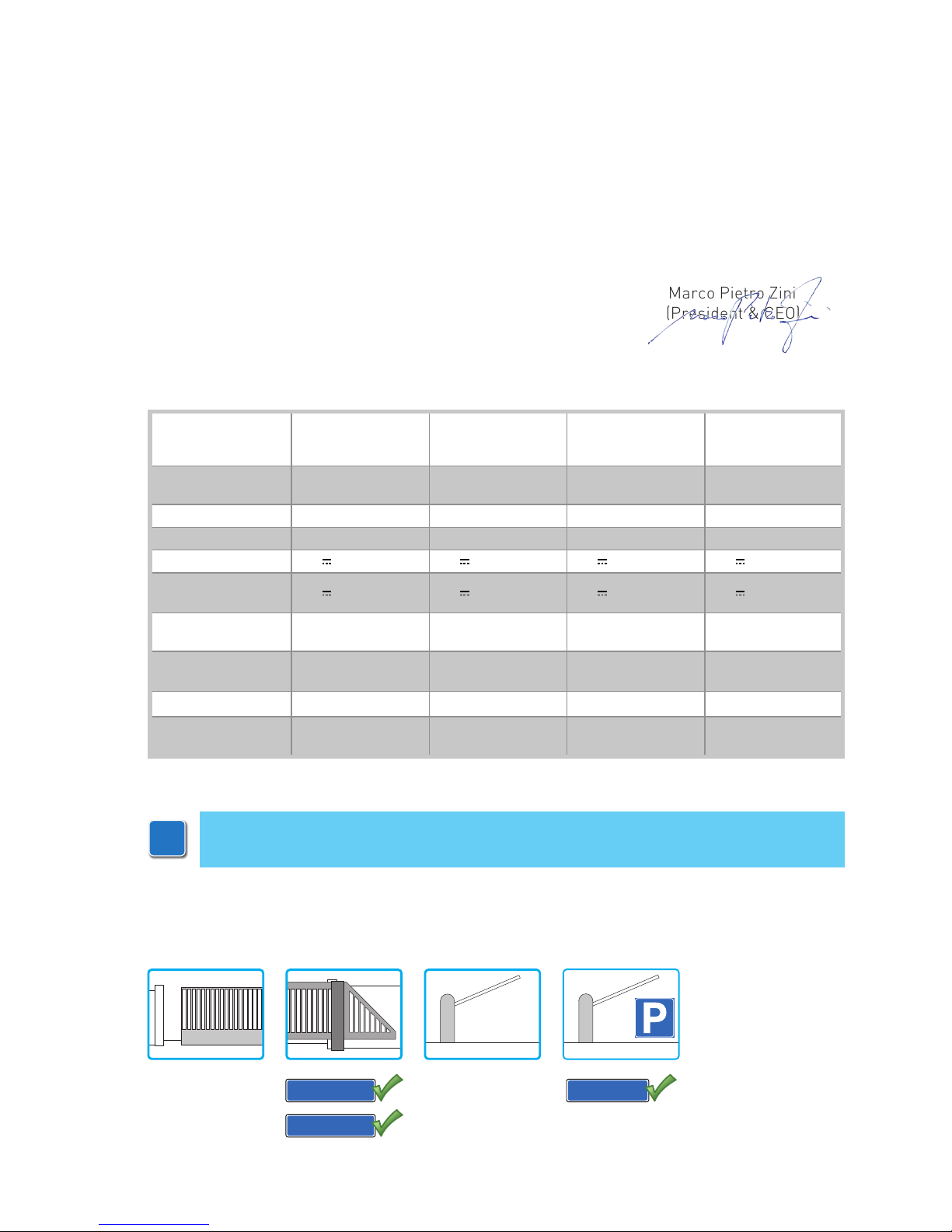
3. Technical specifications
CROSS3E
ALTA5EH
CROSS5EH
CROSS5EH1
ALTA7EH
CROSS7EH
CROSS7EH1
QIK7EH
QIK7YEH
Storage module 3M1CR3
3M1CR5
3M1CR5C5
3M1CR7
3M1CR7C5
3M1QK
3M1QKC7
Power supply 230 V~ 50/60 Hz 230 V~ 50/60 Hz 230 V~ 50/60 Hz 230 V~ 50/60 Hz
F1 fuse
F1,6A F1,6A F2A F1,6A
Motor output
24 V 8 A 24 V 9,5 A 24 V 14 A 24 V 7 A
Accessories
power supply
24 V 0,3 A 24 V 0,3 A 24 V 0,3 A 24 V 0,3 A
Temperature
min -20° C
max +55° C
min -20° C
max +55° C
min -20° C
max +55° C
min -20° C
max +55° C
Degree of
protection
IP24D IP24D IP24D IP24D
Radio frequency
433,92 MHz 433,92 MHz 433,92 MHz 433,92 MHz
Storable transmitters
100
(200-BIXMR2)
100
(200-BIXMR2)
100
(200-BIXMR2)
100 (200-BIXMR2)
i
3.1 Applications
N.B.: The given operating and performance features can only be guaranteed with the
use of DITEC Entrematic accessories and safety devices.
3M1CR5C5
3M1QKC7
3M1CR7C5

32
IP1851EN - 2014-09-30
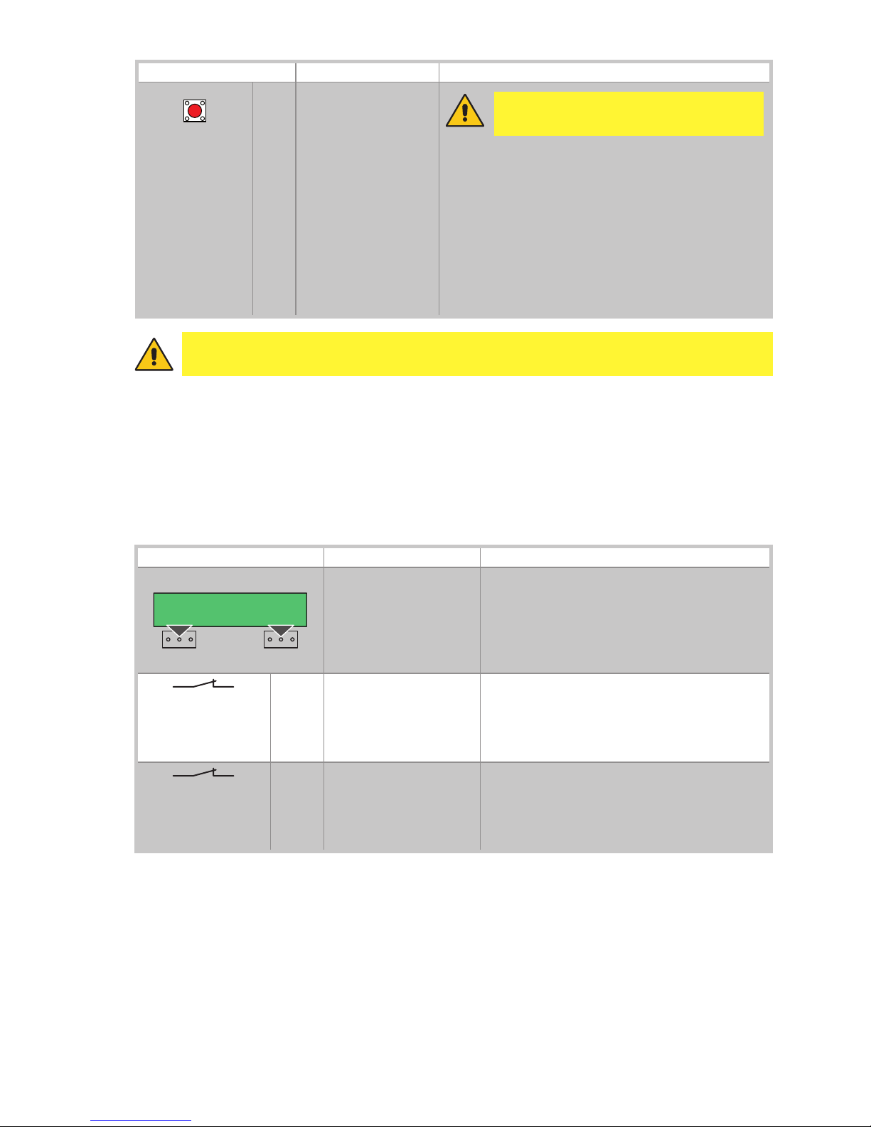
4. Commands
Command Function Description
1 5 N.O. STEP-BY-STEP
WITH AUTOMATIC
CLOSING
With DIP1A=OFF and TC<MAX, closing of the contact
activates an opening or closing operation in the following
sequence: opening-stop-closing-opening.
N.B.: the stop is not permanent, but has the duration set
with the TC trimmer.
STEP-BY-STEP
WITHOUT AUTOMATIC
CLOSING
With DIP1A=OFF and TC=MAX, closing of the contact
activates an opening or closing operation in the following
sequence: opening-stop-closing-opening.
OPENING
WITH AUTOMATIC
CLOSING
With DIP1A=ON and TC<MAX, closing of the contact
activates an opening operation.
OPENING WITHOUT
AUTOMATIC
CLOSING
With DIP1A=ON and TC=MAX, closing of the contact
activates an opening operation.
N.B.: Once the automation stops, command 1-5 performs
the opposite operation to the one performed before the
stop.
1 6
N.O. CLOSING With DIP2B=OFF, closing of the contact activates a clos-
ing operation.
1 6 N.C. OPENING
SAFETY CONTACT
With DIP2B=ON, opening of the safety contact stops and
prevents any movement.
1 8 N.C. REVERSAL
SAFETY CONTACT
Opening the safety contact triggers a reversal of the
movement (reopening) during the closing operation.
1 9 N.C. STOP Opening the safety contact stops the current operation.
1 9
N.O. OPERATOR PRESENT
CONTROL
Opening of contact 1-9 enables the operator present
function.
- opening with operator present 1-5 [with DIP1A=ON
and TC=MAX];
- closing with operator present 1-6 [with DIP2B=OFF].
N.B.: any safety devices, automatic closing and plug-in
cards in the AUX housing are disabled.
1 20
N.O. PARTIAL
OPENING
With DIP3B=ON, closing of the contact activates a partial opening operation.
Once the automation stops, the partial opening control
performs the opposite operation to the one performed
before the stop.
1 20
N.O. AUTOMATIC
CLOSING
With DIP3B=OFF, permanent closing of the contact enables automatic closing.
0 11 N.C. CLOSING LIMIT
SWITCH
Opening of the contact stops the closing operation.
0 12
N.C. OPENING LIMIT
SWITCH
Opening of the contact stops the opening operation.
41 SAFETY TEST With DIP6A=ON, connecting terminal 41 enables a safety
edge test cycle before every operation. If the test fails the
SA LED flashes and the test is repeated.
N.C. SAFETY SWITCH The SAFETY SWITCH contact is connected to the release
system of the automation. Opening the release contact
stops the operation.
CROSSQIK
33
IP1851EN - 2014-09-30
WARNING: make a jumper for all N.C. contacts if not in use. The terminals with the
same number are equal.
4.1 SOFA1-SOFA2 or GOPAVRS self-controlled safety edge
Command Function Description
GOPAV
SOFA1-SOFA2
SAFETY TEST Place the SOFA1-SOFA2 or GOPAVRS device into
the special housing for AUX plug-in cards.
With DIP6A=ON, connecting terminal 41 enables
a safety edge test cycle before every operation.
If the test fails the SA LED flashes and the test
is repeated.
1 6
N.C. SAFETY
STOP
Connect the output contact of the device to terminals 1-6 on the control panel (in series with the
photocell output contact, if installed).
WARNING: if not used, make a jumper for terminals 41-6.
1 8
N.C. REVERSE
SAFETY CONTACT
Connect the output contact of the device to terminals 1-8 on the control panel (in series with the
photocell output contact, if installed).
WARNING: if not used, make a jumper for terminals 41-8.
Command Function Description
PRG
N.O. TRANSMITTER
STORAGE AND
CANCELLATION
Transmitter storage:
- press the PRG key (the SIG LED turns on),
- proceed with transmission from the transmitter to be
stored (the SIG LED flashes),
- wait 10 s for storage to be completed (the SIG LED
turns off).
Transmitter cancellation:
- press the PRG key for 3 s (the SIG LED flashes),
- press the PRG key again for 3 s (the SIG LED flashes
faster).
WARNING: the storage module must
be inserted.
34
IP1851EN - 2014-09-30
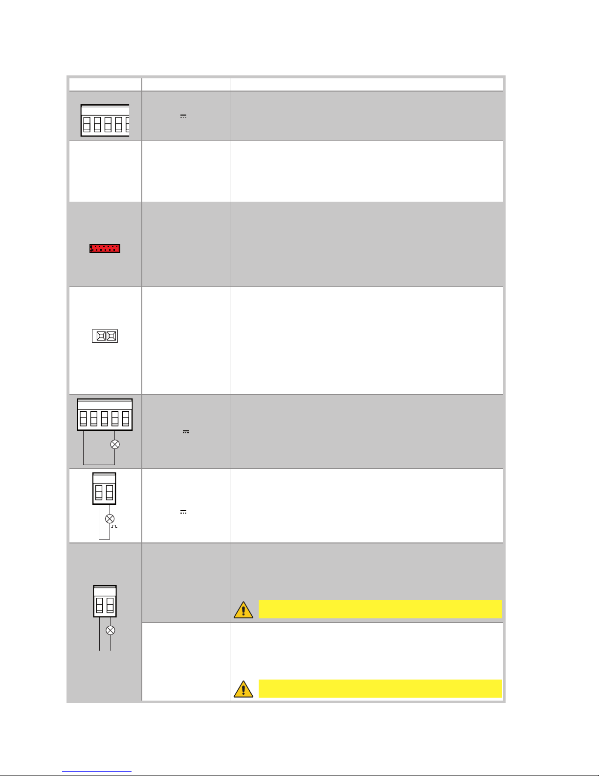
Output Value - Accessories Description
0-1
+
24 V 0.3 A
Accessories power supply.
Power supply output for external accessories, including automation status lamps.
AUX
SOFA1-SOFA2
GOPAV
The control panel is fitted with a housing for a plug-in card, such as
radio receivers, magnetic loops, etc.
Operating of the plug-in card is selected by DIP1A.
WARNING: the plug-in cards must be inserted and removed with
the power supply disconnected.
COM
STORAGE
MODULE
The storage module allows remote controls to be stored and the
type of control panel application to be defined (see TECHNICAL
SPECIFICATIONS on page 4).
If the control panel is replaced, the storage module being used can
be inserted in the new control panel.
WARNING: the storage module must be inserted and removed with
the power supply disconnected.
BAT
BATK3
2x12 V 2Ah
Barrier operation.
The batteries are kept charged when the power supply is on. If the
power supply is off, the panel is powered by the batteries until the
power is re-establish or until the battery voltage drops below the
safety threshold. The panel turns off in the last case.
WARNING: the batteries must always be connected to the control
panel for charging. Periodically check the efficiency of the batteries.
N.B.: the operating temperature of the rechargeable batteries is
approximately +5°C/+40°C.
15913 20
24 V 3 W
Automation status light (proportional)
The light goes off when the automation is closed.
The light comes on when the automation is open.
The light flashes with a variable frequency while the automation is
operating.
14 0
LAMPH
24 V 25 W
Flashing light.
The flashing light activates simultaneously with the opening and
closing operation.
CNO
LN
LUXK3E
LUXK7
230 V~ 60 W
Internal courtesy light.
A courtesy light that turns on for 180 seconds with every opening (total
or partial), step-by-step and closing command can be connected in
series to the NO contact.
230 V~ 400 W
External courtesy light.
An external courtesy light that turns on for 180 seconds with every
opening (total or partial), step-by-step and closing command can
be connected.
WARNING: use a double insulated cable
WARNING: use a double insulated cable
5. Sliding gates outputs and accessories
 Loading...