

Page 1

Ditec DAS801LOK-LOK A
IP2249 • 2018-06-13
Manuale di installazione dispositivo di blocco e leva di sblocco
Installation manual for lock and handle release
leva di sblocco
DAS801LOK
DAS801LOKA
AVVERTENZE GENERALI PER LA SICUREZZA
Il presente manuale di installazione è rivolto esclusivamente a personale professionalmente competente.
Leggere attentamente le istruzioni prima di iniziare l’installazione del prodotto. I materiali dell’imballaggio (plastica, polistirolo,
ecc.) non vanno dispersi nell’ambiente e non devono essere lasciati alla portata dei bambini in quanto potenziali fonti di pericolo.
Prima di iniziare l’installazione verificare l’integrità del prodotto.
Per l’eventuale riparazione o sostituzione dei prodotti dovranno essere utilizzati esclusivamente ricambi originali. Verificare periodicamente il corretto funzionamento dello sblocco manuale.
GENERAL SAFETY PRECAUTIONS
This installation manual is intended for professionally competent personnel only. Read the instructions carefully before begin-
ning to install the product. Packaging materials (plastics, polystyrene, etc.) must not be allowed to litter the environment and
must be kept out of the reach of children for whom they may be a source of danger.
Before beginning the installation check that the product is in perfect condition.
For repairs or replacements of products only original spare parts must be used. Periodically check for correct operation of the
manual release mechanism.
handle release
( DAS801LOK)
www.entrematic.com
Page 2
A
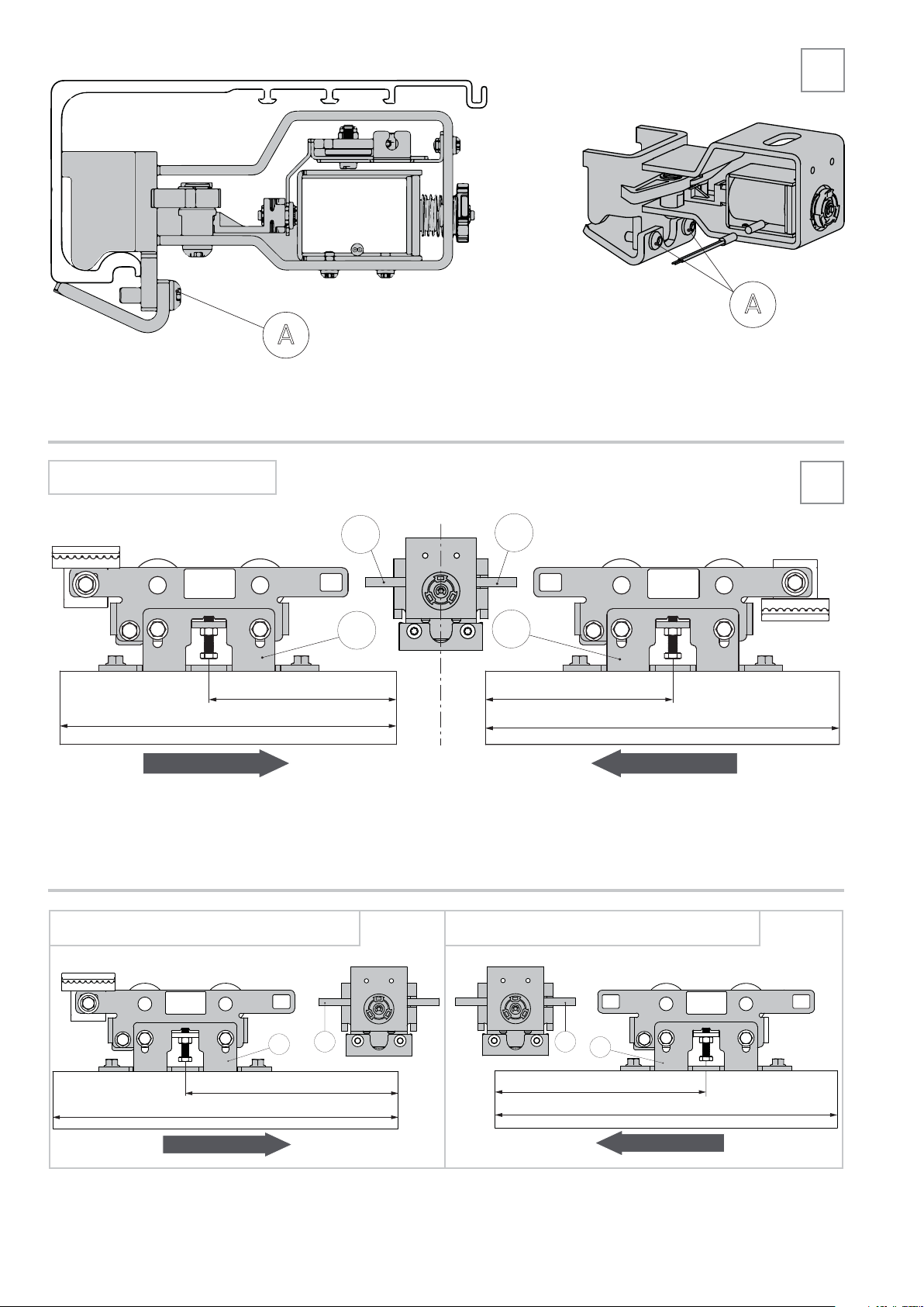
- Fissare come indicato il blocco al cassonetto utilizzando le viti [A in dotazione.
- Fix the blocking device to the box profile using the screws [A supplied, as indicated.
AUTOMAZIONE A 2 ANTE
AUTOMATION WITH 2 DOOR WINGS
1
A
2
C
B
C
B
130 130
LM
CHIUSURA / CLOSING CHIUSURA / CLOSING
- Con le ante chiuse regolare la posizione delle staffe attacco anta B alla distanza indicata per assicurare il corretto aggancio del
blocco C].
- Move the door wings to its closed position, and adjust the position of the wing connection bracket B to the distance indicated, so
as to ensure the correct connection with the block coupling bracket C].
AUTOMAZIONE A 1 ANTA APRE A SINISTRA
AUTOMATION WITH LEFT OPENING DOOR WING
AUTOMAZIONE A 1 ANTA APRE A DESTRA
AUTOMATION WITH RIGHT OPENING DOOR WING
LM
LM
CHIUSURA / CLOSING
B
180
C
2
C
B
180
LM
CHIUSURA / CLOSING
IP2249
Page 3

Installazione della leva di sblocco (DAS801LOK)
Handle release installation (DAS801LOK)
12.5
12.5
20.538
111
52.5
52
3
43
23
G
D
E
F
3
1
2
110
4
- Per aprire la leva di sblocco ruotare la maniglia [F] in senso orario, svitare la vite [E], ruotare la maniglia in senso antiorario, quindi
togliere il cover [D]. Posizionare la base [G] dove richiesto, forare la parete e fissare la base [G] con viti adeguate (non fornite).
ATTENZIONE: La leva di sblocco deve essere installata in una posizione facilmente accessibile così che l’utilizzatore non sia in
situazione di pericolo. La lunghezza massima del cordino e della guaina è di 5 m. La guaina non deve compiere curve strette.
- To open the release handle, turn the handle [F] clockwise, loosen the screw [E], turn the handle anti-clockwise, then take out the
cover [D].
Position the base plate [G] as required, then drill the wall and hold the plate [G] in place with suitable fixing screws (not supplied).
WARNING: the release device must be installed in an easily accessed place, so that the user is not in a dangerous area.
The maximum length of the cord and sheath is 5m. The sheath must not make any sharp bends.
4
- Inserire la cordina nel cassonetto. Se necessario forare il cassonetto nella parte superiore.
- Insert the cable in the box. If necessary, make a hole in the upper part of the box.
IP2249
3
Page 4

20 cm
- Posizionare la cordina vicino al blocco per prendere la misura per accorciarla.
Tagliare la guaina lasciando 20 cm di cordino fuori dalla guaina.
- Place the cord near the lock so as to take measures to shorten it.
Cut off the excess protective sheath leaving 20 cm of cable out of the sheath.
LEVA DI SBLOCCO, INSTALLAZIONE A DESTRA
HANDLE RELEASE, RIGHT INSTALLATION
5
6R
M
J
H
gruppo di sblocco
release group
I
O
- Smontare il blocco dal cassonetto, svitare le viti [O] e togliere le meccanica di sblocco
- Take off the lock from the beam, unscrew the screws [O] and take off the release group.
H
I
J
Destra
Right
7
- Inserire il cordino nel terminale [H], nella molla [I] e nella camma [J].
- Insert the steel cord in the terminal H, spring I and cam J].
4
IP2249
Page 5

LEVA DI SBLOCCO, INSTALLAZIONE A SINISTRA
HANDLE RELEASE, LEFT INSTALLATION
6L
K
Sinistra
J
L
O
- Assemblare la camma [J] con la vite [L] e fissarla con il dado [K]. Il dado deve essere stretto in modo che la camma possa ruotare liberamente.
NOTA: Quando la leva di sblocco è installata a sinistra del blocco, il cordino deve essere inserito prima attraverso il corpo del
blocco e poi si assembla il gruppo di sblocco.
- Assemble the cam J with the screw L and fix it in place with the nut K]. The nut must be tightened to a point that doesn't
prevent the cam from moving freely.
NOTE: When the handle is installed on the left side on the lock, the wire must go through the lock body firstly, then install the
whole handle release assembly.
Left
8
O
Q
- Fissare il gruppo di sblocco sul blocco inserendo la staffa [N] sull’alberino della bobina blocco, come indicato dalla freccia, e
fissarlo con le viti [O].
- Fix the release group to the lock inserting the part [N] on the coil shaft ,where indicated by the arrow,.and fix it by the screws [O].
J
S
M
N
9
Q
- Premere [Q] per posizionare il blocco nella posizione di sbloccato. Tirare il cordino regolando la posizione della camma [J] tangente alla staffa [S] e stringere la vite [M]. Tagliare il cordino in eccesso.
- Push [Q] to make the lock stay at unlock status. Pull the steel cord adjusting the position of cam [J] tangent to the bracket [S]
and tighten the screw [M]. Cut off the excess steel cord.
IP2249
5
M
Page 6

2 mm
2 mm
10
IP2249
T
A
- Installare il blocco sul cassonetto. Regolare la posizione del blocco lasciando circa 2 mm tra i ganci blocco e il carrello.
Avvitare le viti(A). E’ possibile regolare la posizione dei ganci blocco spostando la bobina blocco allentando le viti (T)
- Install the lock on the beam. Adjust the position of lock and make sure distance about 2mm between lock hook and carriages.
Tighten screws [A]. It’s possible adjust the position of the lock hooks by moving the coil group loosening the screws [T].
P
11
D
E
3
2
- Regolare il registro [P] in modo da avere una corretta tensione del cordino e bloccarlo con il controdado.Eseguire alcune manovre
di sblocco per verificare il corretto funzionamento della leva di sblocco. Chiudere la leva sblocco con la vite [E].
- Intervene on the adjuster [P] to obtain the correct cord tension, then lock it in place with the locknut. Replace the cover [D].
Perform some release operations to check the release handle is working properly. Close the release handle with the screw [E].
- Collegare il blocco ai morsetti 18-19 del quadro elettrico. Consultare il manuale installazione DAS107PLUS per maggiori
informazioni.
- Connect the lock to terminal 18-19 of the control unit. See DAS107PLUS installation manual for more details.
Tutti i diritti relativi a questo materiale sono di proprietà esclusiva di Entrematic Group AB.Sebbene i conte-nuti di questa pubblicazione siano stati redatti con la
massima cura, Entrematic Group AB non può assumersi alcuna responsabilità per danni causati da eventuali errori o omissioni in questa pubblicazione. Ci riserviamo
il diritto di apportare eventuali modifiche senza preavviso. Copie, scansioni,ritocchi o modifiche sono espres-samente vietate senza un preventivo consenso scritto di
Entrematic Group AB .
All the rights concerning this material are the exclusive property of Entrematic Group AB.
Although the contents of this publication have been drawn up with the greatest care, Entrematic Group AB cannot be held responsible in any way for any damage
caused by mistakes or omissions. We reserve the right to make changes without prior notice.
Copying, scanning and changing in any way are expressly forbidden unless authorised in writing by Entrematic Group AB.
Entrematic Group AB
Lodjursgatan 10
SE-261 44, Landskrona
Sweden
www.entrematic.com
12
 Loading...