

Page 1
IP2266EN • 2019-06-14
Technical manual
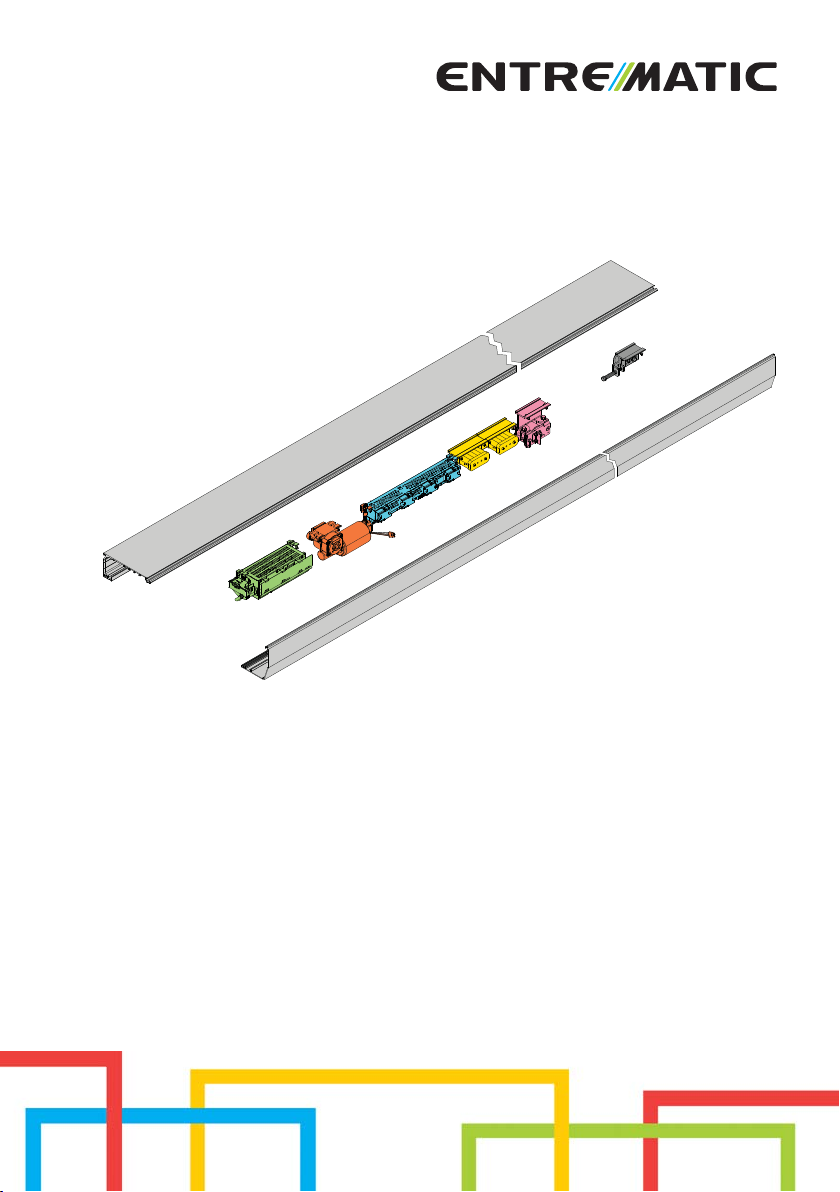
Ditec DAS200
DAS200HD-DAS200RF-DAS200RG
Sliding doors automation
(Original instructions)
www.entrematic.com
Page 2

Contents
Subject Page
1. General safety precautions 3
Declaration of incorporation of partly completed machinery 4
2. Technical data 5
2.1 Operating instructions 5
3. Standard installation 6
4. Main components 7
5. Installing the automation 8
5.1 Installing / Removing the cover 8
5.2 Installation/removal of the cover if installed side presence sensor 9
6. Fastening of box using supplied wing anchoring brackets 10
6.1 Examples with DAS11M8 11
6.2 Examples with DAS18M8 12
6.3 Example with DAS35M8 13
6.4 Example with DAS40M8 14
6.5 Example with ACV 14
7. Preparation of the glass door wing 15
7.1 Installing and adjusting the door wings 16
7.2 Installing the floor guides 18
7.3 Checking and adjusting the belt tension 19
7.4 Sensor positioning on the cover 19
7.5 External sensor cable fixing 19
8. Electrical connections 20
8.1 Electrical connections 21
8.2 Control panel commands 23
8.2.1 Commands 23
8.3 DAS902MP plus module (optional) 25
8.4 DAS902MP commands 26
9. Adjustment and selection of control functions 28
9.1 Display test 29
9.2 Status indication on the display 29
10. Start up 30
11. Parameters 32
11.1 Configuration parameters according to function 32
11.2 Main control board parameters 36
12. Example of connection 46
13. Troubleshooting 48
13.1 Active error indication 49
14. Routine maintenance plan 53
EN
Key
This symbol indicates instructions or notes regarding safety, to which special attention must be paid.
This symbol indicates useful information for the correct functioning of the product.
i
2
IP2266EN
Page 3

1. General safety precautions
Failure to respect the information given in this manual
may cause personal injury or damage to the device.
Keep these instructions for future reference
This assembly and installation manual is intended exclusively for the use of qualified personnel.
Installation, electrical connections and adjustments must be performed by qualified personnel, in
accordance with Good Working Methods and in compliance with the current regulations.
Read the instructions carefully before installing the product.
Incorrect installation could be dangerous.
The packaging materials (plastic, polystyrene, etc.) should not be discarded in the environment
or left within reach of children, as they are a potential source of danger.
Before installing the product, make sure it is in perfect condition.
Do not install the product in explosive areas and atmospheres: the presence of inflammable gas
or fumes represents a serious safety hazard.
Before installing the motorisation device, make all the necessary structural modifications to
create safety clearance and to guard or isolate all the crushing, shearing, trapping and general
hazardous areas.
Make sure the existing structure is up to standard in terms of strength and stability. The motorisation device manufacturer is not responsible for failure to observe Good Working Methods when
building the frames to be motorised, or for any deformations during use.
The safety devices (photocells, safety edges, emergency stops, etc.) must be installed taking into
account the applicable laws and directives, Good Working Methods, installation premises, system
operating logic and the forces developed by the motorised door or gate.
The safety devices must protect against crushing, cutting, trapping and general danger areas of
the motorised door or gate.
Display the signs required by law to identify hazardous areas.
Each installation must bear a visible indication of the data identifying the motorised door or gate.
When necessary, connect the motorised door or gate to an effective earthing system that complies
with the current safety standards.
During installation, maintenance and repair operations, cut off the power supply before
opening the cover to access the electrical parts.
The automation protection casing must be removed by qualified personnel only.
The electronic parts must be handled using earthed antistatic conductive arms. The manufac-
turer of the motorisation device declines all responsibility if component parts not compatible
with safe and correct operation are fitted.
Only use original spare parts when repairing or replacing products.
The installer must supply all information concerning the automatic, manual and emergency operation of the motorised door or gate, and must provide the user with the operating instructions.
IP2266EN
3
EN
Page 4

Declaration of incorporation of partly completed
g
Mat
Mat
teo
t
machinery
We:
Entrematic Group AB
Lodjursgatan 10
SE-261 44 Landskrona
Sweden
declare under our responsibility that the following types of equipment:
Ditec DAS200, Ditec DAS200HD, Ditec DAS200RF, Ditec DAS200RG
comply with the following directives:
2014/30/EU Electromagnetic Compatibility Directive (EMCD)
2006/42/EC Machinery Directive (MD) for the following essential health and safety requirements: 1.1.2, 1.2.1, 1.2.2, 1.2.3, 1.2.4.2, 1.2.6, 1.3.9, 1.4.3, 1.7.2, 1.7.4, 1.7.4.1, 1.7.4.2
Technical documentation for safe integration supplied.
Harmonised European standards which have been applied:
EN 60335 -1:2012+A13:2017 EN ISO 13849 -1:2015 EN 61000 -6-2:2005
EN 60335-2-103:2015 EN 16005:2012/AC:2015 EN 61000 -6-3:2007+A1:2011
Other standards or technical specifications, which have been applied:
IEC 60335-1: 2010 ed.5 IEC 60335-2-103:2006+A1:2010 AutSchR: 1999
DIN 18650-1:2010 DIN 18650-2:2010
The production process aims to guarantee that the equipment complies with the technical
documentation.
The production process is regularly assessed by an independent body.
The equipment must not be put into service until the final door system installed has been
declared compliant with the Machinery Directive 2006/42/EC by the installer.
Person in charge of technical data sheet:
Matteo Fino E-mail: matteo.fino@entrematic.com
Entrematic Group AB
Lodjursgatan 10
SE-261 44 Landskrona
Sweden
Place Date Signature Position
Landskrona 2018-06-14 Matteo Fino Entrance Automation President
Fi
4
EN
IP2266EN
Page 5
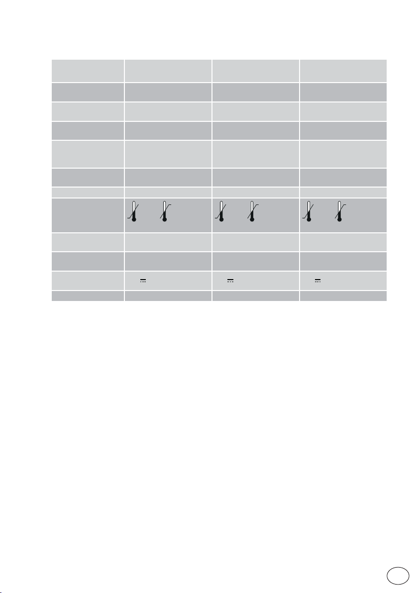
2. Technical data
Ditec DAS200
Power supply
Power supply rated
power (PS)
Max Opening speed
(2 door wings)
Maximum load
Service class
Intermittence S3=100% S3=100% S3=100%
Temperature
Degree of protection
Control panel
(MCU/MCU-ER)
Accessories power
supply
Durability test 1.000.000 cycles 1.000.000 cycles 1.000.000 cycles
110V~ / 240V~
50/60Hz
75W 150W 150W
1,3m/s 1,4m/s 1,4m/s
120kg (1 wing)
200kg (2 wings)
5
(HEAVY DUTY)
-20°C +50°C
(FOR INTERNAL USE ONLY)
1DAS20QE 1DAS20HDQE 1DAS20RGQE
24V
IP20
0,64A 24V 1A 24V 1A
Ditec DAS200HD
Ditec DAS200RF
110V~ / 240V~
50/60Hz
150kg (1 wing)
DAS200HD 280kg (2 wings)
DAS200RF 240kg (1 wing)
5
(HEAVY DUTY)
-20°C +50°C
IP20
(FOR INTERNAL USE ONLY)
Ditec DAS200RG
110V~ / 240V~
50/60Hz
150kg (1 wing)
280kg (2 wings)
5
(HEAVY DUTY)
-20°C +50°C
IP20
(FOR INTERNAL USE ONLY)
2.1 Operating instructions
Service class: 5 (minimum 5 years of working life with 600 cycles per day).
Applications: HEAVY DUTY (for entrances with very intense pedestrian use).
• The performance characteristics refer to the recommended weight (approx. 2/3 of the maximum weight allowed). When used with the maximum permissible weight a reduction in
the above mentioned per formance can be expected.
• The service class and number of consecutive cycles should be taken merely as a rough
indication. having been statistically determined under average operating conditions, and
are therefore not necessarily applicable to specific conditions of use.
• Each automatic entrance has variable elements such as: friction, balancing and environmental factors, all of which may substantially alter the performance characteristics of
the automatic entrance or curtail its working life or parts thereof (including the automatic
devices themselves). The installer should adopt suitable safety conditions for each particular installation.
IP2266EN
5
EN
Page 6
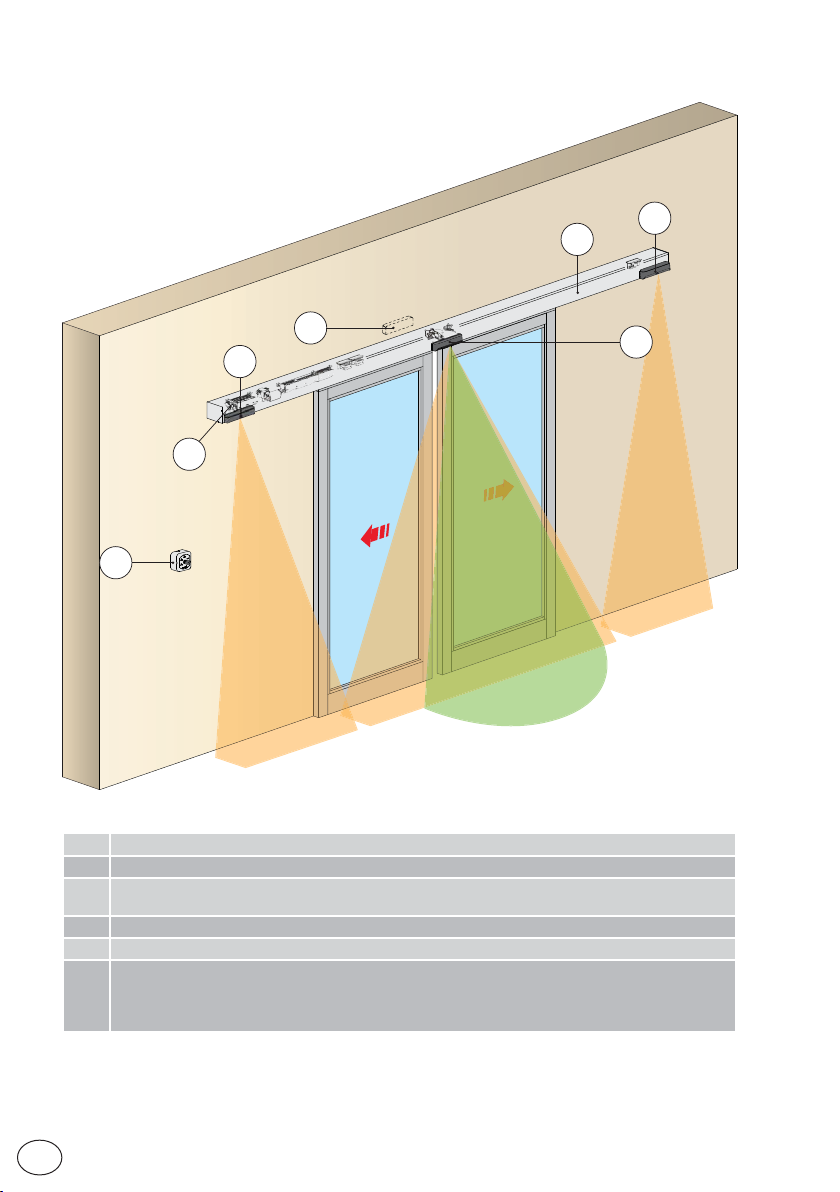
3. Standard installation
4
1
3
2
4
A
5
Ref. Description
1 Automation for sliding doors
2
Combined opening and safe closing sensor
3
4 Safe opening sensor
5 Safety photocell
A Connect the power supply cable to a type-approved omnipolar switch with category III insulation and
a contact opening distance of at least 3 mm.
The connections to the mains and low voltage wires must be made on an independent channel separated from the connections to the command and safety devices (SELV = Safety Extra Low Voltage).
EN
IP2266EN
6
Page 7
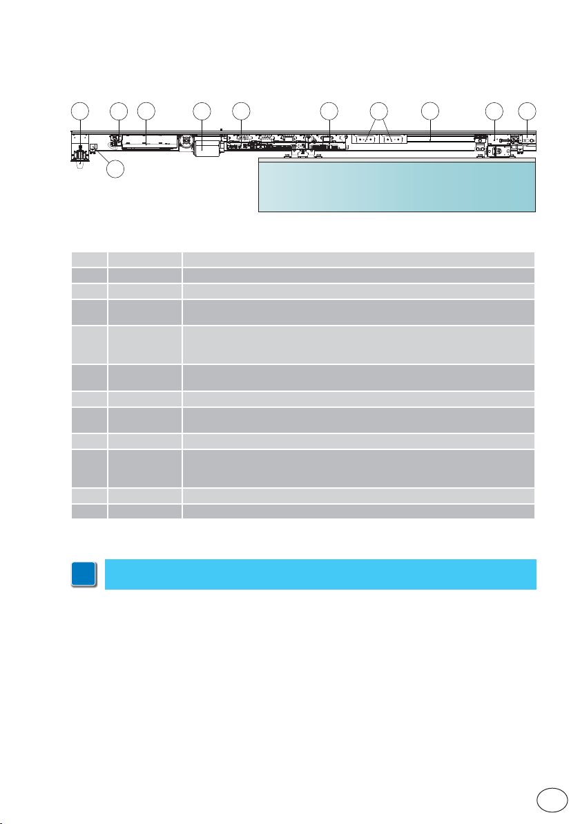
4. Main components
6
8
7
10 11
9
16
Ref. Code Description
6 DASLOKSB Built-in manual release device (optional)
7- Mains power supply
1DAS20AL
8
1DAS20HAL
1DAS20MR
9
1DAS20HMR
1DAS20RGMR
1DAS20QE
10
1DAS20RGQE
11 DAS902MP DAS902MP plus module
DAS901BAT1
12
DAS902BAT2
13 DAS802B50 Drive belt
DAS802LOK
14
DAS802LOKA
DAS802LOKB
15 - Belt transmission
16 - Mechanical stops
75W power supply unit (PS)
150W power supply unit (PS)
DAS200 gearmotor
DAS200HD gearmotor
DAS200RG gearmotor
DAS200-DAS200HD-DAS200RF (MCU) control panel
DAS200RG control panel (MCU-ER)
12V batteries
24V batteries
Standard lock. Locked with power - LD
Anti-panic lock. Locked without power - LDP
Bi-stable lock-LDB
12
13
14
15
IP2266EN
NB: the given operating and performance features can only be guaranteed with the
i
use of DITEC Entrematic accessories and safety devices.
7
EN
Page 8
5. Installing the automation
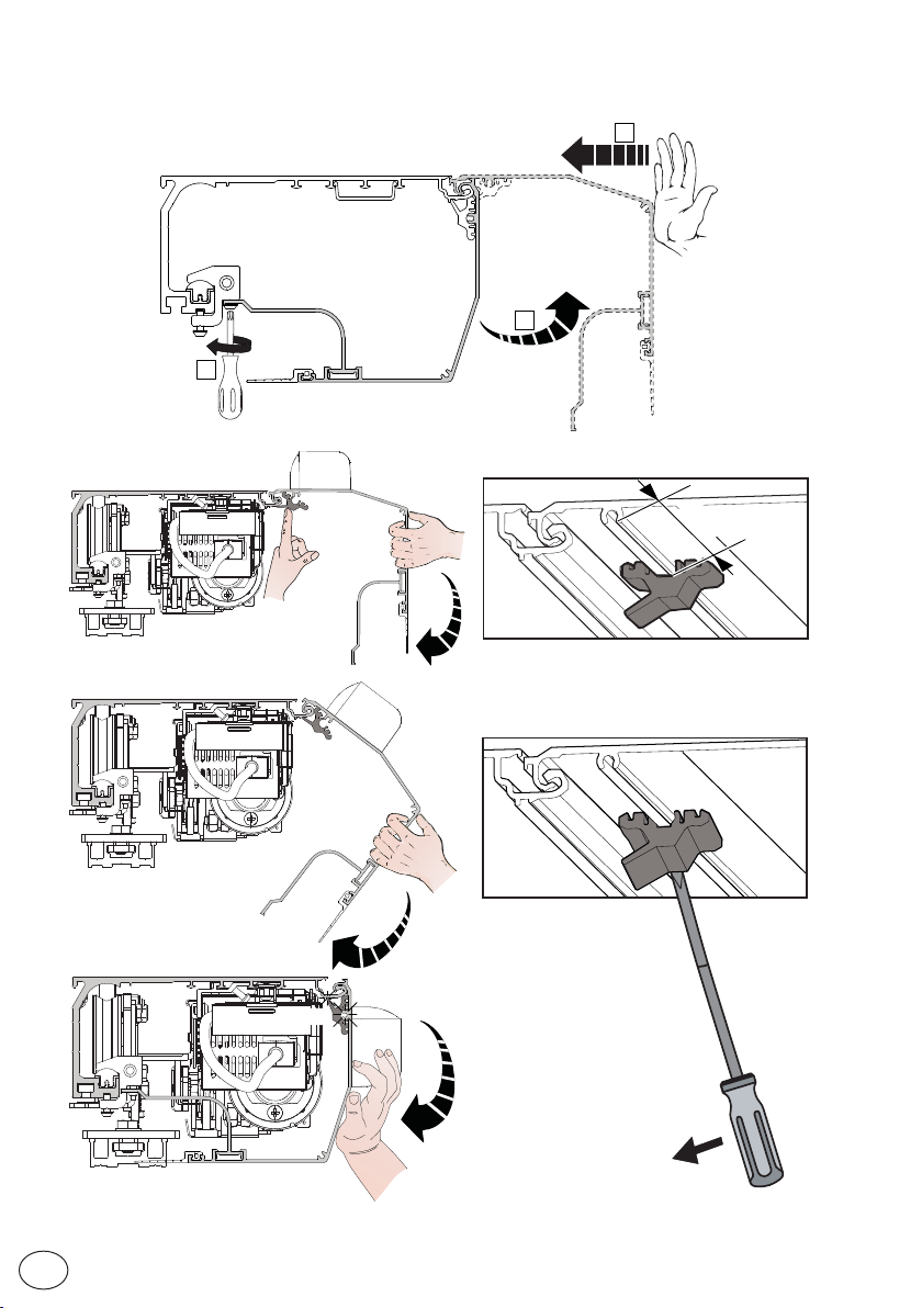
5.1 Installing / Removing the cover
1
• Secure and unsecure the open cover as shown below.
3
2
500
EN
CLICK
IP2266EN
8
Page 9
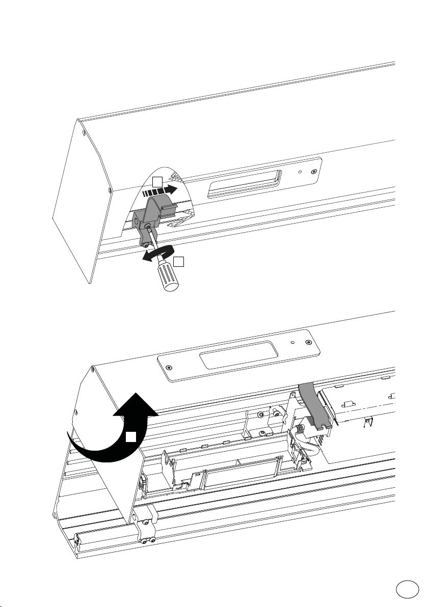
5.2 Installation/removal of the cover if installed side presence
sensor
2
1
IP2266EN
3
9
EN
Page 10
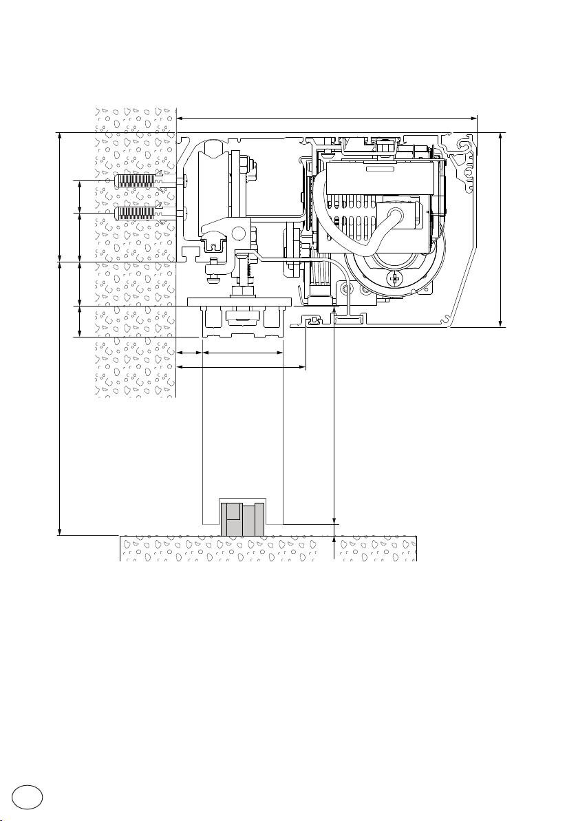
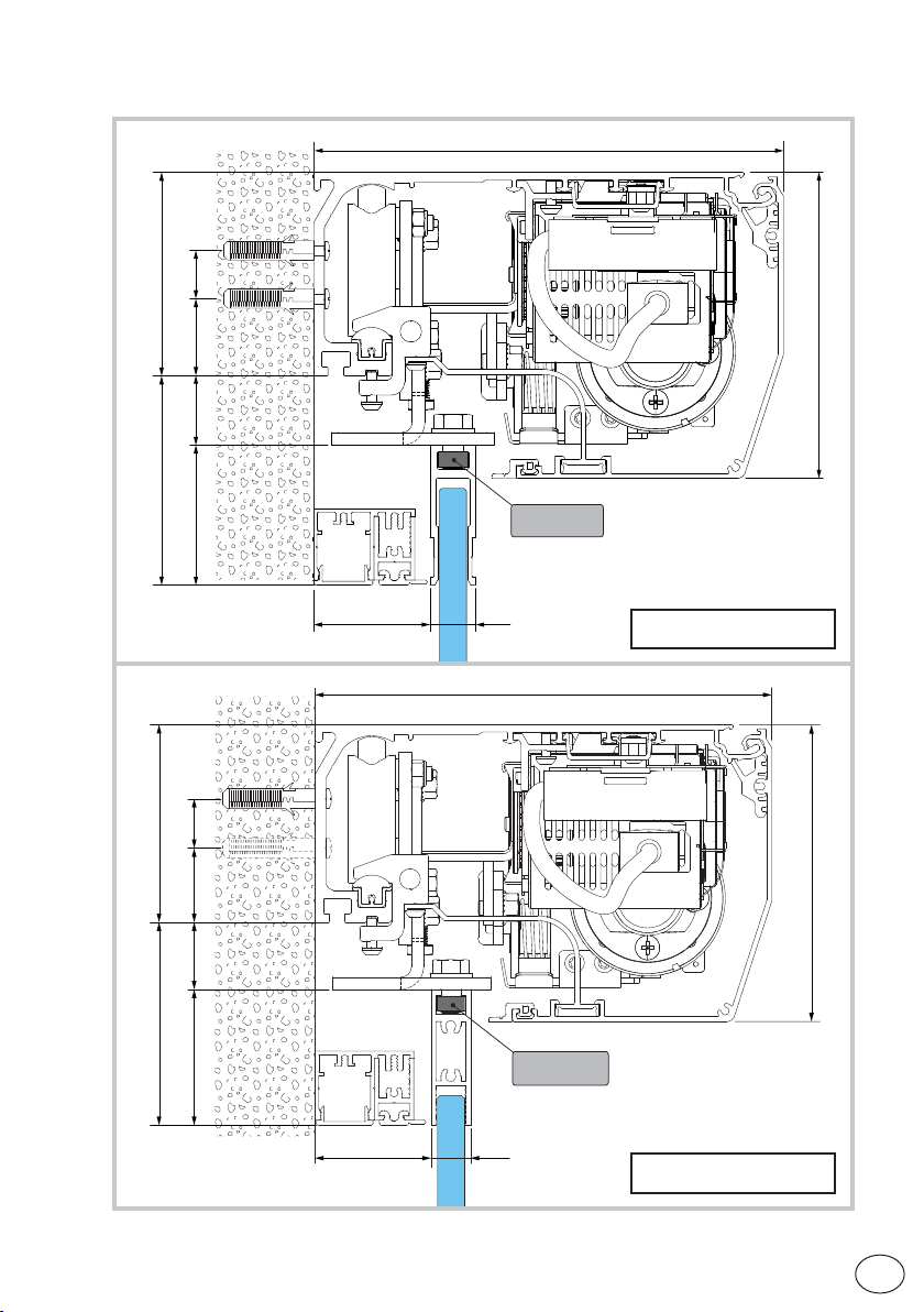
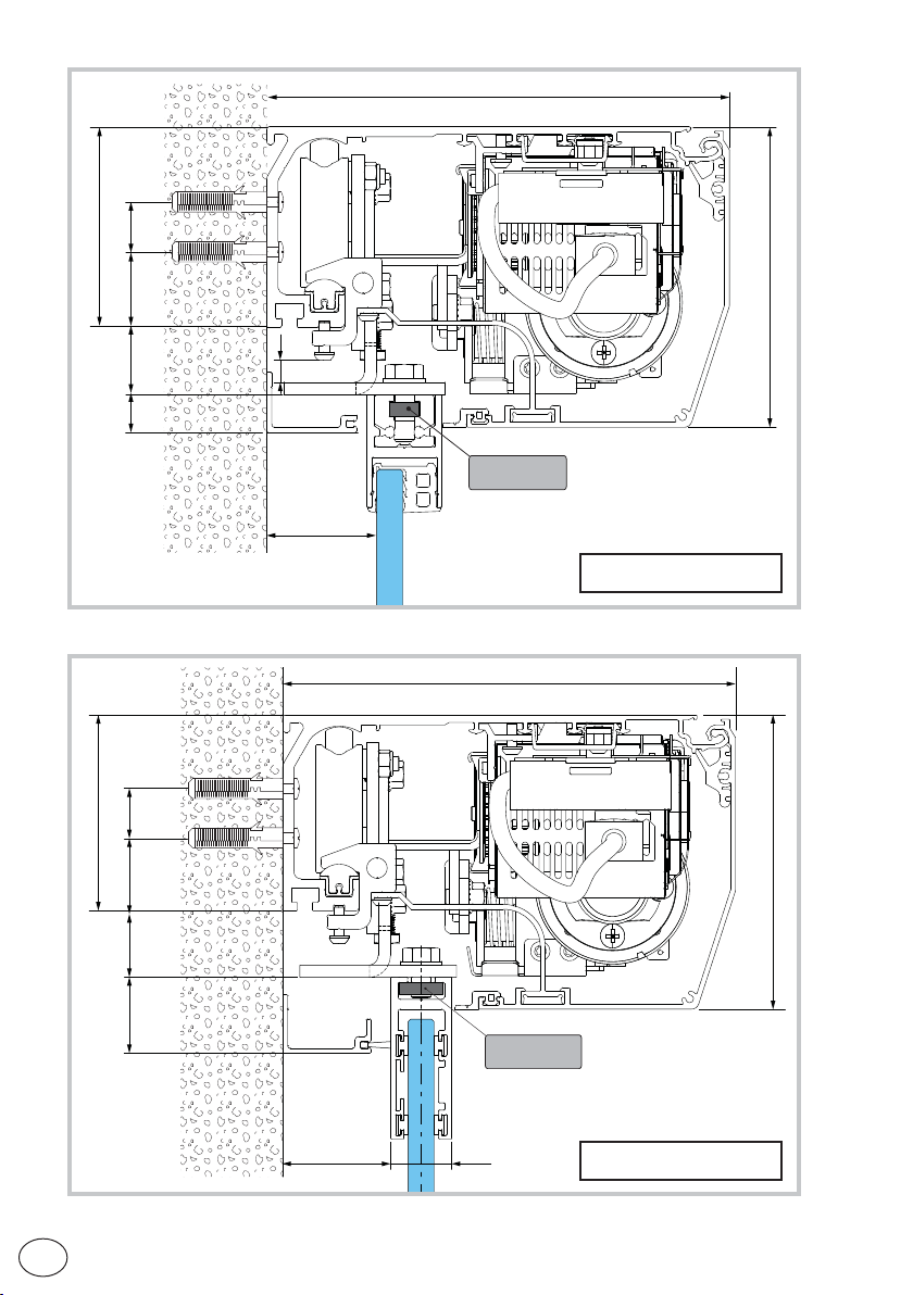
6. Fastening of box using supplied wing anchoring brackets
185
80H
2030
19 27
16
50
80
HM= H-37
120
10
Unless otherwise specified, all measurements are expressed in millimetres (mm).
The figure shows the measurements for fastening the automation to the wall, considering that the
automation door wings are made using profiles not manufactured by us.
If the door wings are made with DITEC profiles in the ALU/PAM series: refer to the measurements
given in the relative manuals.
Drill a hole in the box using the reference line on the back and fasten it with M6 Ø12 steel plugs
or 6MA screws (not supplied).
Distribute the fixing points approx. every 400 mm.
Make sure the box is positioned evenly, with its back surface perpendicular to the floor and not
deformed lengthwise by the shape of the wall. If the wall is not straight and smooth, iron plates
must be fixed to it and then the box in turn fixed to the plates.
WARNING: the fastening of the box to the wall must be sufficient to sustain the door wing weight.
WARNING: do not damage the wheel guide during assembly. Clean the guide thoroughly before
installing the wings.
10
EN
IP2266EN
Page 11
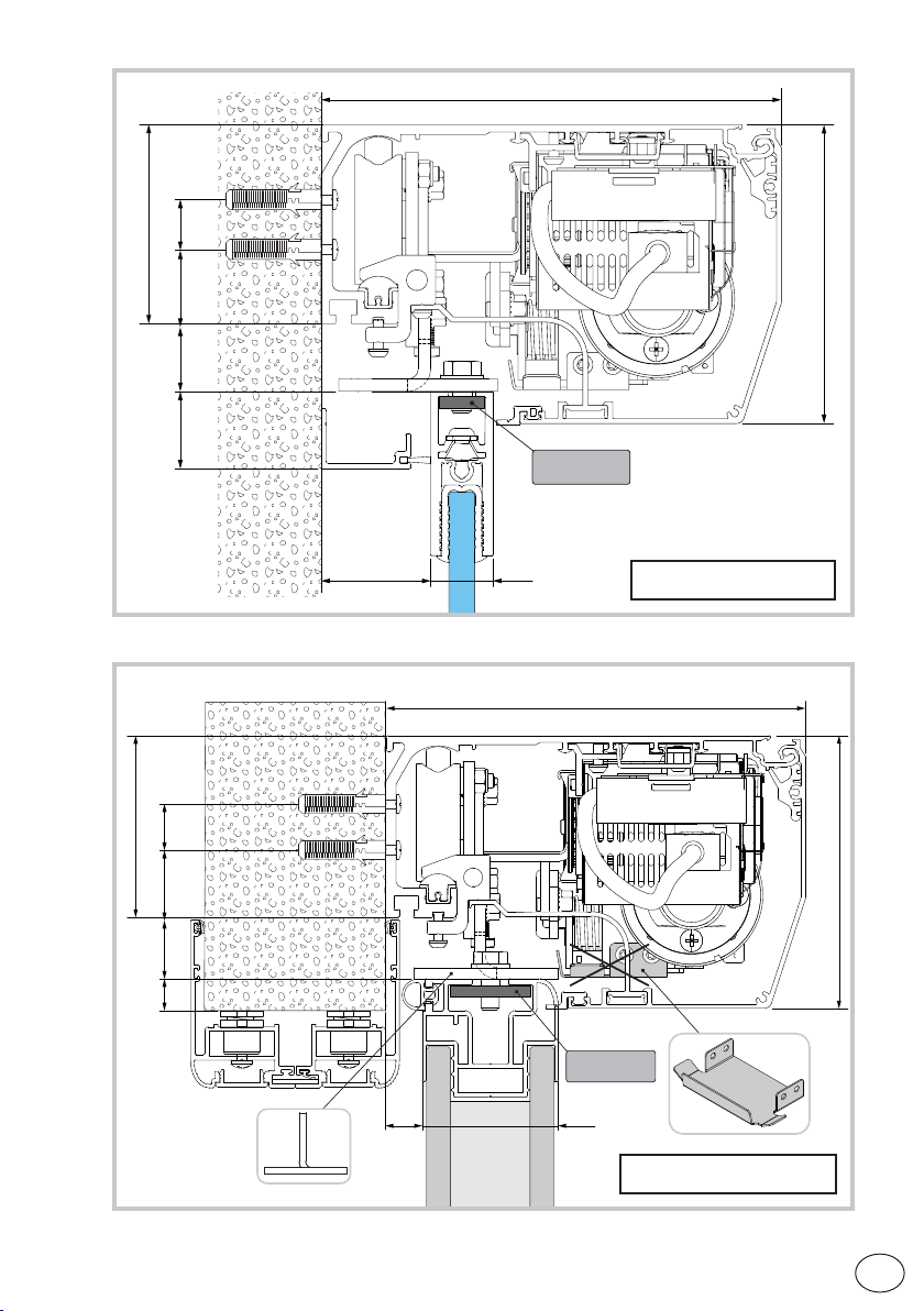
6.1 Examples with DAS11M8
2030
8082
2755
185
120
DAS11M8
IP2266EN
46 18
185
20302755
8082
DAS200-AC1356
185
DAS11M8
47 16
DAS200-PAM16
11
EN
Page 12
80
2030
9
15 27
55
6.2 Examples with DAS18M8
185
120
DAS11M8
DAS200-PAM30
185
EN
80
2030
120
31 27
DAS18M8
44 25
DAS200-AC4255
IP2266EN
12
Page 13
185
80
2030
120
31 27
DAS18M8
6.3 Example with DAS35M8
80
2030
14 27
IP2266EN
44 25
185
DAS35M8
16 60
DAS200-PAMH60
DAS200-AC4870
120
13
EN
Page 14
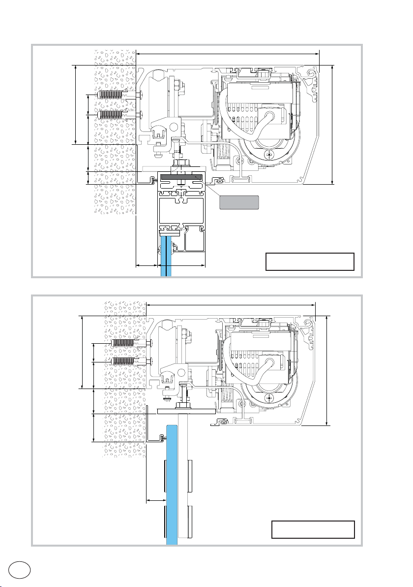
6.4 Example with DAS40M8
80
2030
13 27
185
120
DAS40M8
6.5 Example with ACV
80
2030
31 27
22
22
48
185
DAS200-ALU48
120
DAS200-ACV
IP2266EN
EN
14
Page 15
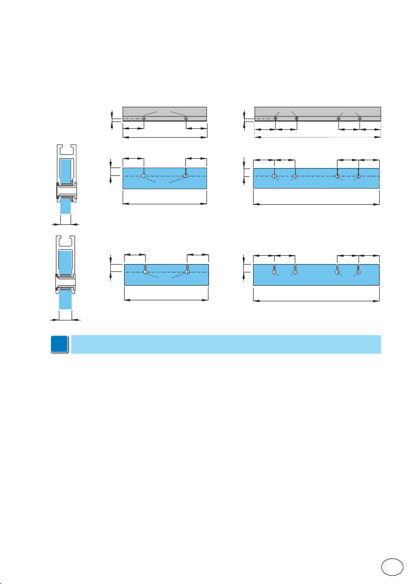
7 Preparation of the glass door wing
The diagram indicates the process measurements of the aluminium profile AC1356 and glass.
Ø10 through holes are required on the aluminium profile and Ø15 on the glass for fastening. The
number of holes and related distance between centres are based on the door wing width. Silicon
should ideally be used between the edge of the glass and the internal base of the profile.
Ø10
11
100
L≤1000
30
Ø15
L≤1000
10
30
12
With AC4255 or AC4870 glass wing attachment applications, see the respective ma-
i
nual.
Ø15
L≤1000
100
100100
100100
11
3030
Ø10
100 100 100 100
L>1000
100 100 100 100
Ø15 Ø15
L>1000
100 100 100 100
Ø15
L>1000
Ø10
Ø15
IP2266EN
15
EN
Page 16

7.1 Installing and adjusting the door wings
D
+/- 8
A
A
13
A
+/- 19
B
C
B
10
CB
B
10
0,5
D
Make sure that the central wheel [D] is adjusted as illustrated in the picture.
Fix the door wing to the carriage with screws (A).
The door wing can be adjusted as shown in the figure.
• Loosen the screws [B] and adjust the height by turning the screws [C];
• Adjust the side position of the door wing by turning the screws [A];
• Move the door wings manually and make sure they move smoothly and freely and that all
the wheels rest on the guide.
WARNING: for all-glass door wings without seals, leave a gap of at least 10 mm in the closed position
to avoid contact between the glass sheets.
16
EN
IP2266EN
Page 17
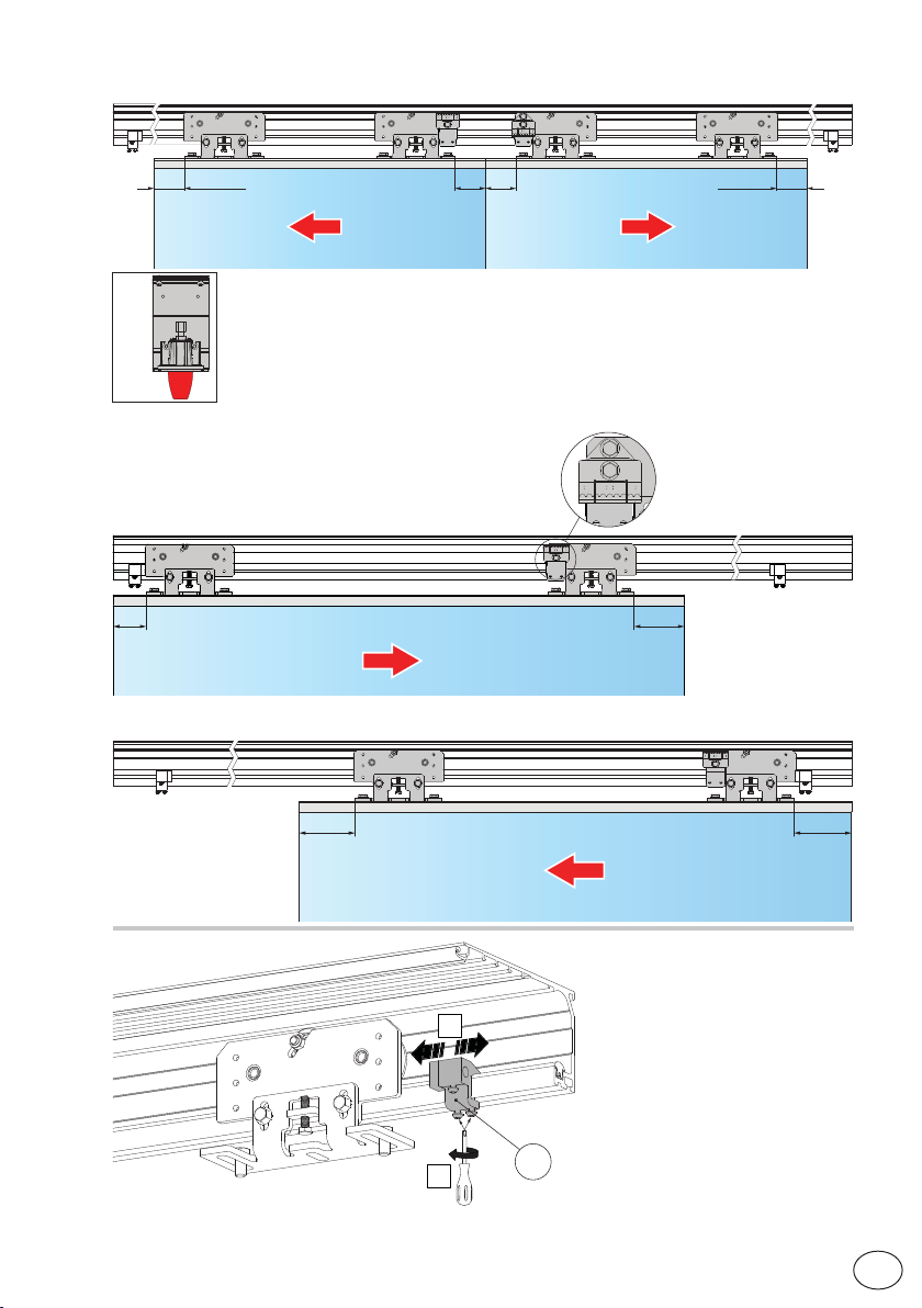
Automation with two door wings
60 (100*)
60 60
*se
*if
*si
*ob
*si
*se
Automation with one door wing with right-hand
opening
60
Automation with one door wing with left-hand opening
100
se
if
si
ob
si
se
60 (100*)
DAS200RG
IP2266EN
100100
Place the end stops (16) on the
opening and closing positions.
2
For the 2 wing automations, a
third end stop is provided which
must be placed near the end of
the box which is used as a stop for
the cover support.
1
16
17
EN
Page 18

7.2 Installing the floor guides
The floor guides must be made of an anti-friction material such as PVC, NYLON or TEFLON.
The length of the floor guide should be no greater than the overlap between the fixed and mobile
door wings, and should not enter the passage opening.
Examples of floor guides
KP515AB
KP48
10
22
50
46
min 21
max 40
HM
10
EN
K4345
18
KAMC16KP369
IP2266EN
Page 19

7.3 Checking and adjusting the belt tension
LT ≤ 3000 = 2 mm
5
LT > 3000 = 3 mm
1
6
10
3
T20
2
4
5
10
2
5
7.4 Sensor positioning on the cover
7.5 External sensor cable fixing
4
cable fixingexternal sensor cable tie
2
1
≥18
4
6
IP2266EN
19
EN
Page 20

8. Electrical connections
Connect the automation to an efficient earthing system that complies with current safety
standards.
During installation, maintenance and repair operations, cut off the power supply before opening
the cover to access the electrical parts.
The automation protection casing must be removed by qualified personnel only.
An omnipolar disconnection switch with a contact opening distance of at least 3 mm must be fitted
on the mains supply.
Check there is an adequate residual current circuit breaker and overcurrent cutout upstream of
the electrical system.
Install an electric switch next to the automatic system.
Make sure there are no sharp edges that may damage the power supply cable.
If the power cable is damaged, have it replaced by the manufacturer or qualified personnel.
• Use a H05RN-F 3G1,5 or H05RR-F 3G1,5 type electric cable.
• Remove the protective cover [1].
• Connect the power cable [2] to the terminal board [4], locking it in place with the cable fastener [3].
• Replace the protective cover [1].
• Connect the connection cable [5] to the power supply unit [6].
LN
4
2
3
5
1
6
IP2266EN
EN
20
Page 21

8.1 Standard electrical connections
PS
A
MCU
C
program selector (0MS)
D
C
B
A
B
F
B
C
A
MCU-ER
D
C
B
E
DAS902BAT2 (24 V)
DAS901BAT1 (12 V)
DAS902MP
F
E
DAS902MP
IP2266EN
Left side presence
sensor
FUTURE USE
Inner combination
sensor
LEARN/EXIT
MMI
Right side presence
UP
DOWN
21
E
E
sensor
Outer combination
sensor
SELECT
EN
Page 22

Output Description
A
Power supply unit connection
green LED
D
jumper
E
B
F
Motor connection
Encoder connection
C
Connection for:
- Program selector;
- Network connection of interconnected operators;
- Connector for Bluetooth interface;
Green LED: If this LED is switched off or flashing, it means the control
panel is malfunctioning.
JUMPER: For interconnecting more than two units (control unit and/or
operation mode selectors).
DAS901BAT1 - DAS902BAT2 battery kit connection (optional)
In the event of a power failure the operator will carry out an opening
operation (factory setting).
See parameters 10, 38 , 40 and 41 for selection of continuous operation
and monitoring with DAS902BAT2.
NOTE: Monitoring will be made if parameter 10 is set to Convenience
Monitoring (01).
To charge the batteries, connect the mains power and the battery kit at
least 30 minutes before starting the system.
WARNING: for charging purposes, the battery kit must be connected to
the control panel at all times. Periodically check the efficiency of the
battery kit. When there is no voltage, the door can only be opened with
a KEY com-mand connected between 8-12.
NOTE: use battery type 12V, 1,2mAh NiMH.If a different type of battery is
used it can damage!
DAS200RG motor connection
EN
IP2266EN
22
Page 23

8.2 Control panel commands
Jumper the unused N.C. contacts
20
19
18
17
16
15
14
13
12
11
10
9
8
7
6
5
4
3
2
1
8.2.1 Commands
1
(ref. parameter 27)
1
(ref. parameter 46)
1
(ref. parameter 28)
1
6
(ref. parameter 29)
1
7
IP2266EN
DO NOT USE
Blocking device
Blocking device
(+) 24V
Inner side opening
(-) 0V
(+) 24V
Central presence sensor test
Key opening
blocking device connection
}
(main coil)
NOTE: Power supply output for external
accessories 24V .
0,64 A: DAS200;
1 A: DAS200HD-DAS200RF-DAS200RG.
The maximum absorption of corresponds
to the sum of all terminals power supply
output (1-7; 8-14; 15-17)
Central presence sensor 2
Inner impulse (motion) monitoring
Central presence sensor 1
(use this contact if used only one sensor)
(-) 0V
(+) 24V
Side presence sensor test
Outer side opening
Side presence sensor 2
Stop
Side presence sensor 1
(use this contact if used only one sensor)
(-) 0V
Contact Description
2
N.C.
3
N.C. STOP
4
N.C.
5 N.O.
-
+
SIDE
PRESENCE
SENSOR 1
SIDE
PRESENCE
SENSOR 2
OUTER SIDE
OPENING
SIDE
PRESENCE
SENSOR TEST
POWER SUPPLY
TO
ACCESSORIES
Connect side presence sensor 1 as shown in the example in
paragraph 12.
The opening of the safety contact causes the current operation
to stop.
WARNING: when the contact closes again, the door closes.
WARNING: The emergency opening (battery 12V), is priority
(=door opens in case of mains power failure even if STOP
contact is open).
Connect side presence sensor 2 as shown in the example in
paragraph 12.
Connect the external sensor as shown in the example in paragraph 12.
The closure of the contact activates the door opening operation.
Connect the test clamp of the side sensors.
Clamp 6 activates a test on the side safety sensors before every
operation.
If the test fails, an alarm message appears on the display.
accessories power supply.
24 V
23
EN
Page 24

Contact Description
8
(ref. parameter 07)
10
(ref. parameter 16)
8
(ref. parameter 08)
8
(ref. parameter 04)
13
(ref. parameter 09)
8
14
15 16 N.O.
15
17 +
18
(ref. parameter 05)
9
11
12
+
-
19
CENTRAL
N.C.
PRESENCE
SENSOR 1
INNER IMPULSE
(MOTION)
MONITORING
CENTRAL
N.C.
PRESENCE
SENSOR 2
N.O. KEY OPENING
CENTRAL PRESENCE SENSOR
TEST
POWER SUPPLY
TO
ACCESSORIES
INNER SIDE
OPENING
POWER SUPPLY
TO
ACCESSORIES
BLOCKING
DEVICE
CONNECTION
(main coil)
Connect central presence sensor 1 as shown in the example
in paragraphs 12.
Connect the test clamp of the escape route. If the test fails, an
alarm message appears on the display.
Connect central presence sensor 2 as shown in the example
in paragraph 12.
Closing the contact via a key command activates an opening
operation and a closing operation after the time selected by
parameter 04.
If used for opening in DOOR CLOSED mode:
•In the presence of a mains power supply or continuity batteries,
a 8-12 command partially opens the door and closes it after
the time selected by parameter 04.
•If there is no mains power supply, a 8-12 command reactivates
the batteries, if present, for the time required to perform a complete opening operation and then the batteries are disconnected
from the control panel.
Connect the test clamp of the presence sensors.
Command 13 activates a test on the central safety sensors
before every operation. If the test fails, an alarm message
appears on the display.
accessories power supply.
24V
Connect the internal sensor as shown in the example in paragraph 12.
The closure of the contact activates the door opening operation.
accessories power supply.
24V
Output for connecting an electro-mechanical block (optional).
The blocking device is automatically selected during the learning
phase (except bistabel lock).
EN
IP2266EN
24
Page 25

8.3 DAS902MP plus module (optional)
For extra functionality like:
• close impulse;
• nurse impulse;
• open/closeimpulse;
• emergency open impulse (fireman’s opening);
• bi-stable lock;
• connection of optional operation mode selector;
• fire impulse;
• sustainable function off;
• relay out put for external erroror status indication, maximum 15W, 42VAC/ 30VDC (SELV),
resistive load only;
• interlock off (interconnected operators);
• second monitored inner impulse;
• mode selector COM500ER enable impulse.
IP2266EN
25
EN
Page 26

8.4 DAS902MP commands
22
21
20
NC
COM
NO
19
18
17
16
15
14
13
12
11
10
9
8
7
6
5
4
3
2
1
Contact Description
1
(ref. parameter 93)
1 3
(ref. parameter 90)
1
(ref. parameter 91-92)
1
(ref. parameter 96)
1
(ref. parameter 99)
2
N.O.
N.O.
4
N.O.
5
N.C.
6
max 15
error / status
42V~ / 30V (SELV)
}
RESISTIVE LOAD ONLY
Fire
External alarm loop
12-24V
Fire
}
Bistable lock
(auxiliary coil)
}
(+) 24V
Open
Auto partial
Exit
Off
Reset
(-) 0V
(+) 24V
Battery wake up
Sustainable drive mode OFF /mode selector enable
Emergency open
Open /Close / Inner impulse 2 monitoring / Interlock OFF
"Nurse" function / Interlock out
Close/ Inner impulse 2
(-) 0V
a) CLOSE
b) INNER IMPUL-
SE 2
a)“NURSE”
FUNCTION
b) INTERLOCK
OUT
a) OPEN/CLOSE
b) INNER
IMPULSE 2
MONITORING
c) INTERLOCK
OFF
EMERGENCY
OPEN
a)
SUSTAINABLE
DRIVE MODE OFF
b) MODE SELEC-
TOR ENABLE
USE ONLY to have
priority on the function
selector or in the absence
of function selectors
}
a) Close impulse.
b) When two inner impulses are to be used. Sets input to inner
impulse 2.
a)The door will open to partial opening in operation mode se-
lections EXIT, AUTO and PARTIAL.
b) When configuring for interlock also set parameter 6A = 01.
a) One impulse opens the door the next impulse closes the door.
Available in mode EXIT, AUTO, PARTIAL.
b) Inner impulse 2 monitoring for the second inner impulse. Set
also parameter 93=03.
c) Disables interlock, both doors can be open at the same time.
d) When configuring for interlock also set parameter 6A = 01.
Used to give opening (fireman’s opening) impulse to the door in
any operation mode selector setting. With electrical emergency
unit also during power failure.
a) Disables Sustainable drive mode.
b) Enable the Mode Selector with a key (only COM500ER).
Interlock in
/
IP2266EN
EN
26
Page 27

1 7 N.O.
1
8 +
-
BATTERY WAKEUP IF NO MAIN
POWER
POWER SUPPLY
TO ACCESSORIES
The impulse opens the door fully and stop there.
24V accessories power supply.
Connection of additional functions (ref. parameter 97)
Contact Description
9 10 N.O. RESET It deletes all the data learned by the control panel.
9
9
9
9
9
15 +
16
(ref. parameter 98)
18
19
(ref. parameter 36)
11 N.O. OFF The door closes and remains closed and locked (if lock is present).
12 N.O. EXIT For one-way operation from the inside of the door.
13 N.O. AUTOPARTIAL For two-way partial opening.
14 N.O. OPEN The door opens and remains open.
-
Contact Description
POWER SUPPLY
TO ACCESSORIES
17
BISTABLE LOCK
(AUXILIARY COIL)
FIRE ALARM
CIRCUIT
CONNECTION
24V accessories power supply.
Power supply for bistable lock (auxiliary coil)
Fire closing or Emergency opening.
Example of connection:
18
19
or
9
15
18
19
12-24V external alarm loop
N.C.
N.O.
IP2266EN
Contact Description
20 21 22
ERROR / STATUS
A door / alarm status signaling device can be connected.
max 15W
42V ~ / 30V
only resistive loads
(SELV)
27
EN
Page 28

9. Adjustment and selection of control functions
The control panel has a two-figure display that displays text and/or numbers.
It has four buttons. (MMI)
UP
1
UP
LEARN / EXIT
LEARN / EXIT SELECT
The procedure to switch on the display is as follows:
press the 2-SELECT key to launch the display test
NB: make sure all seven segments of the two displays light up correctly to avoid incorrect reading.
- 1 UP: to increase the parameter number or value in it;
- 2 SELECT: to enter a parameter or value to be programmed in the memory;
- 3 DOWN: to decrease the parameter number or value in it;
- 4 LEAR/EXIT:
• LEARN has 3 functions: 1, 2, 3.
1. Quick learning. If pressed for longer than 1 second but less than 2, the electronic
accessories connected to the control board are recognised.
2. Normal learning. If pressed for longer than 2 seconds, the display flashes . Two
seconds after releasing the button, a complete learning cycle begins which performs an
opening and closing operation to carry out the operations described in chapter 8.
3. Restore factory settings. If pressed for longer than 10 seconds, the control panel
restores the factory settings.
• EXIT quits the parameter menu or value without saving the changes. If EXIT is not
pressed, the control panel returns to the default display after 3 minutes of inactivity.
4
3
DOWN
DOWN
SELECT
2
N.B.: the set value is stored by the control panel by pressing SELECT irrespective of whether the
value has been modified or not. Press EXIT if you do not want to store the value.
When a value is programmed, that parameter is excluded from the learning cycle. Even if a new
learning cycle is executed, that value will not be modified.
To include the parameters in the learning cycle again, the factory settings must be set.
28
EN
IP2266EN
Page 29

9.1 Display test
a. When the display shows " ", push the SELECT button and each of the two display win-
dows make a rotating test pattern.
b. Verify that all seven segments of the two display windows are lit during the test. If not there is
a risk of misjudgment of the digits shown in a defective display.
c. When the display test is finalized the display shows two steady digits indicating the first parameter.
Display
Char
act er
Display
Char
act er
Display
Char
act er
Display
Char
act er
Display
Char
act er
9.2 Status indication on the display
The display shows the different impulses that are active. The status viewing starts with showing
“ ” as for Status, then one or many numbers representing the different active impulses in to
the operator.
The different impulses are:
00= Key Impulse
01= Inner impulse
02= Outer impulse
03= Synchronisation
05= Presence impulse 1
06=Presence impulse 2
07= Side Presence impulse 1
08= Side Presence impulse 2
09= Stop impulse
10= Emergency open impulse
13= Close command
14= Nurse impulse
24= Push and Go impulse
25= Open-Close impulse
28= Fire impulse
47= Interlock Disable
IP2266EN
29
EN
Page 30

10. Start up
NOTE: for DAS200RF follow the start up procedure indicated in the DA S200RFKA kit
i
manual.
Before per forming any type of oper ation, make sure that the automation is turned off
and the batteries are disconnected.
Start-up and adjustment must be performed in the following order when the automation is installed:
1. Connect the accessories, opening and safety sensors, blocking device, batteries and selector.
2. Jumper the safety contacts 1-2, 1-3, 1-4, 8-9, 8-11 on the control panel and 1-5 on plus
module DAS902MP, if not used.
3. Connect the mains power supply to the automation.
4. Set the following parameters:
Parameter Description Settings
Lock configuration (main control)
05
Central presence sensor test
09
Selection of opening direction
12
Inner Impulse (motion) Monitoring
16
Side presence sensor test
29
Selection of the type of automation
67
Lock Configuration, terminal 16-17
98
DAS902MP
Set ONLY if installed bistable lock DAS802LOKB. 12= bistable
lock.
10= No lock.
11= Antipanic lock (locked with power – LDP).
12= Standard lock (locked without power – LD) and bi-
stable lock (LDB).
00= None (factory setting).
01= Presence sensor 1 (set if a presence sensor with
monitoring is installed).
02= Presence sensor 1 and 2 (set if two presence sensors
with monitoring are installed).
00= right hand opening for single door wing automation.
01= left hand opening for single door wing automation and
for double door automation (factory setting).
According to EN16005 or DIN18650 it is a demand to have
Inner impulse monitoring= On in escape routes.
00= Disables monitoring.
01= Enables monitoring.
NOTE: on DAS200RF set to 01.
NOTE: on DAS200RG this parameter is set to 01.
00= None ( factory setting)
01= Presence sensor 1 (set if a presence sensor with
monitoring is installed).
02= Presence sensor 1 and 2 (set if two presence sensors
with monitoring are installed).
00= Automation with one door wing.
01= Automation with two door wings.
NOTE: Set ONLY if installed bistable lock DAS802LOKB.
11= bistable lock
EN
NOTE: Parameter 10 ( Emergency Unit Monitoring ) on DAS00RG is not visible and it is
i
set up on 02= redundant monitoring
30
IP2266EN
Page 31

5. *Leave ajar the casing and, if there are safety sensors, check that they are in standby mode
and that there are no people or objects moving in the sensors detection area.
*
6. Press the LEARN button for 2 seconds, the display flashes .
To enable the stroke and weight of the door wings to be acquired correctly, the acquisition phase must be per formed with the door wings installed.
7. Free the area of action of the sensors so that they are detected and monitored during the
learning cycle.
8. The automation performs opening and closing operations.
During this cycle, the following accessories connected to the control panel are recognised and
some parameters detected:
Accessory / Parameter Parameter number
High Speed Closing 02
Presence of block and type, except bistable lock 05, 06, 98
Whether the sensors are monitored or not 9, 16, 29, 31, 91
Presence of battery and type 41
Power supply type 64
Door type 67
Measurement of width of passage opening -
Calculation of weight of door wing(s) 68
Calculation of friction in the system 69
At the end of the learning cycle, the door remains closed and the display indicates .
If some parameters have not been automatically configured during the learning cycle, the door
opens. The display first indicates , and then the parameter that has not been acquired automatically, for example, if the door is a 2-wing or 1-wing door (parameter 67).
These parameters must be configured by the installer and/or check that there are no obstacles
and friction which prevents correct learning.
IP2266EN
31
EN
Page 32

1. Press the SELECT button to start to modify the parameters.
2. Press SELECT again to display the parameter value in flashing mode.
3. Select the correct value using the UP and DOWN buttons.
4. Press SELECT to confirm and program the selected value.
5. Continue to configure the other parameters that have not been acquired
6. Press LEARN/EXIT for more than 2 seconds and the display will indicate , after 2 seconds,
the door closes and is ready for operating.
If necessary, you can adjust the following main parameters:ain parameters:
Parameter Description Settings
High Speed Opening (cm/s) 10÷70cm/s
00
High Speed Closing (cm/s) 10÷70cm/s
02
Hold Open Time (00÷60s)
03
Partial opening (00-99%)
11
Performance adjustment. Sets how fast or slow the
Run Program (01÷05)
15
Convenience battery 24V,
38
DAS902BAT2 (00÷01)
Opening Max Force (02÷23N x10)
49
door shall accelerate or break.
01= Smooth, for light doors.
05= Max Performance. For heavy doors.
00= Off
01= On
NOTE: on DAS200RG this display is not visible and is
set to 00.
If the reopening maneuver occurs too abruptly, set
parameter 49 with a value lower than the factory value
(10), example 04 - 05.
• For other parameter variations, see the “Parameters” chapter.
• Make sure the installation complies with the current regulations and the essential requisites laid down by the relevant authorities.
• At the end of the start-up close the cover and fix it with the appropriate screws, see chapter 5.1.
EN
IP2266EN
32
Page 33

11. Par ameters
11.1 Configuration parameters according to function
For more information on the parameters, see paragraph 9.2
SPEED parameters
Parameter Description Range
High speed opening
00
Low speed
01
High speed closing
02
TIME parameters
Parameter Description Range
03 Hold open time 00÷60s
04 Key hold open time 00÷60s
20 Partial hold open time 00÷60s
21 Push & Go hold open time 00÷60s
22 Auto width activation time 00÷60s
23 Auto width resume time 00÷60s
24 Jam hold time 00÷10s
25 Interlock disable time 00÷60s
26 Presence hold open time 00÷60s
92
(DAS902MP)
Parameter Description Range
IP2266EN
Open/Close timeout ref. terminal 4 00÷03
FUNCTION parameters
5E Status indication. Off (00) / On (01) 00÷01
5F Default programming. Off (00) / On (01) 00÷01
Opening direction. 1 wing Right (00) / 1 wing Left or 2 wings (01).
12
On DAS200RG not selectable
13 Hold force 00÷60N
2A Side presence function. Safe speed (00) / Stop door (01) 00÷01
32 Active brake on stop. Off (00) / On (01) 00÷01
33 Push & Go in EXIT mode selection. Off (00) / On (01) 00÷01
34 Hold force in EXIT and OFF mode selection. Off (00) / On (01) 00÷01
35 Toggle operation mode selector after stop. Off (00) / On (01) 00÷01
53 Operator type. Slider (00) / mechanical emergency unit DAS200RF (04) 00÷04
54 Service Needed Operating Hours 00÷60h x 1000
55 Service needed opening cycles
60 Learn. Off (00) / On (01) 00÷01
61 Auto width. Off (00) / On (01) 00÷01
65 Sustainable Drive Mode. Off(00) / On(01) 00÷01
6A Interlock function. Off (00) / On (01) 00÷01
6B Synchronizing Function. Off(00) / On(01) 00÷01
6C External bus device ID 00÷99
10÷70cm/s
05÷70cm/s
10÷70 cm/s
00÷01
00÷50 x
100.000
33
EN
Page 34

FUNCTION parameters
Parameter Description Range
6D Extended hold open time function. Off (00) / On (01) 00÷01
67 Door type. Single sliding (00) / Biparting (01) 00÷01
90
(DAS902MP)
91
(DAS902MP)
93
(DAS902MP)
99
(DAS902MP)
Function select terminal 3. No function (00) / Nurse function (01) / Interlock
out (03)
Function select terminal 4. No function (00) / Open/Close function (01) / Interlock
disable (02) / inner impulse 2 monitoring (03) / Interlock in (04)
Function select terminal 2. No function (00) / Close function (01) / Inner impulse
2 (03)
Function select terminal 6. No function(00) / Sustainable Disable (01)/
Selector Disable (02).
00÷03
00÷04
00÷03
00÷02
POSITION parameters
Parameter Description Range
11
57
58
Partial open position
Low speed distance, opening
Low speed distance, closing
00-99%
00-99cm
00-99cm
DRIVE parameters
Parameter Description Range
15 Run program. Smooth (01) to max performance (05) 01÷05
49 Opening max force 02÷23N x10
4A End checking closing thrust 00÷23N x10
50 Closing max force 02÷23N x10
64 Power supply type.150W (01) / 75W (02) 00÷02
68 Door weight 00÷40kg x10
69 Friction 00÷99N
70 Motor type. DAS200 (15) / DAS200HD-RF (16) / DAS200RG (17) 15÷17
71 Max motor power 03÷15W x10
EMERGENCY parameters
Parameter Description Range
10
36 Emergency action. Closing (00) / opening (01) 00÷01
37 Emergency Action in OFF Mode. Off (00) / On (01) 00÷01
38 Convenience battery. Off (00) / On (01) 00÷01
40 Emergency unit test interval 04÷23hours
41 Battery type. No battery (00) / 12V (01) / 24V (02) 00÷02
94
(DAS902MP)
95
(DAS902MP)
96
(DAS902MP)
Emergency unit monitoring. Off (00) / Convenience monitoring (01) / Redundant
monitoring (02)
Fire impulse function terminal 18/19. Off (00) / On (01) 00÷01
Emergency open impulse function 5. Off (00) / On (01) 00÷01
Emergency button configuration 5. N.O. (00) / N.C. (01) 00÷01
34
EN
00÷02
IP2266EN
Page 35

LOCK parameters
Parameter Description Range
(DAS902MP)
Lock configuration (main control). No lock (10) / antipanic (11) / standard and
05
bistable (12)
06 Lock release. Off (00) / On (01) 00÷01
43 Opening delay for lock 00÷99s x0,1
44 EXIT lock. Off (00) / On (01) 00÷01
51 Push & Close. Off(00) / On (01) 00÷01
52 Push & Close Timeout 00÷99s x10
98
Lock configuration terminal 16/17. No lock (10) / bistable (11) 10÷11
10÷12
SENSOR parameters
Parameter Description Range
07 Presence impulse 1 configuration. N.O. (00) / N.C. (01) 00÷01
08 Presence impulse 2 configuration. N.O. (00) / N.C. (01) 00÷01
09 Presence impulse monitoring. None(00)/sensor 1(01)/sensor 1 and 2(02) 00÷02 units
16 Inner impulse (motion) monitoring. Off (00) / On (01) 00÷01
27 Side presence input 1 configuration. N.O. (00) / N.C. (01) 00÷01
28 Side presence input 2 configuration. N.O. (00) / N.C. (01) 00÷01
29 Side presence impulse monitoring. None (00) / sensor 1 (01) / sensor 1 and 2 (02) 00÷02 units
30 Side presence activation distance 00÷99dm
31 Sensor type.1-wire (00) / 2-wire (01) monitoring 00÷01
45 STOP function. Off (00) / On (01) 00÷01
46 STOP configuration. N.O. (00) / N.C. (01) 00÷01
91
(DAS902MP)
93
(DAS902MP)
Function select terminal 4. No function (00) / Open / Close function (01) / Interlock
disable (02) / inner impulse 2 monitoring (03)
Function select terminal 2. No function (00) / Close function (01) / inner impulse
2 (03)
00÷04
00÷03
OPERATION MODE SELECTOR parameters
Parameter Description Range
B0 Operation mode selector variant. Electronic program selector (04) 00÷04
B1 Operation mode selector key lock. Off (00) / Hold for 2 s.(01) /Passcode (02) / key (03) 00÷03
B2 Operator mode selector service indication. Off (00) / On (01) 00÷01
Choose priority of the operation mode selector. The lower the number the higher
B3
the priority.
B4 Choose group of the operation mode selector. 00÷10
Choose display mode of the operation mode selector. Show system mode (00) /
B5
Show local mode (01)
Choose terminal mode of the operation mode selector. The buttons are disabled
B6
(00) / adapts to system mode (01) / it si setting the operation mode (02)
B7 Mode selector, self service indication. Off (00) / On (01) 00÷01
B8 Mode selector, key impulse. Disabled (00) / Login required (01) / Enabled (02) 00÷02
Bluetooth Power Mode. Always disabled(00), Disabled in OFF mode(01), Always
B9
enabled (02).
Default(02)
25÷29
00÷01
00÷02
00÷02
IP2266EN
35
EN
Page 36

11.2 Main control board parameters
In the “INSTALL ATION SETTINGS” column you can note the modified setting values.
i
Parameter Description
High Speed Opening (cm/s)
Sets the maximum opening speed.
DAS200 (10÷70, 10= 10cm/s; 70= 65cm/s).
DAS200HD/RF/RG (10÷70cm/s).
Low speed
(05÷70, 05= 5cm/s; 69= 69cm/s; 70= automatic)
The low speed is self adjusting to optimal operation if this
parameter is set to max. Depending on authority or installation requirements the low speed, distance opening and/
or closing can be further reduced.
High Speed Closing (cm/s)
Sets the maximum closing speed.
DAS200 (10÷70, 10= 10cm/s; 70= 65cm/s).
DAS200HD/RF/RG (10÷70cm/s).
Hold Open Time (00÷60s)
The general hold open time for inner and outer impulses.
Key Hold Open Time (00÷60s)
Hold open time for key impulse.
Lock Configuration (main control) (10÷12)
10= No lock.
11= Antipanic lock (locked with power – LDP).
12= Standard lock (locked without power – LD) and bi-stable
lock (LDB).
*NOTE: the bistable block is not automatically learned and
must be selected 12.
Lock release (00÷01)
00= Off
01= On
If“LockRelease”is On the door will apply force in the closing
direction when the lock is un locking.This is made to prevent
a lock from being stuck in locked position when opening.
*NOTE: set 01 if using bistable lock.
*NOTE: on DAS200RG this parameter is set to 01.
Presence Impulse 1 Configuration (00÷01)
00 = N.O.
01= N.C.
Presence Impulse 2 Configuration (00÷01)
00= N.O.
01= N.C.
Presence Impulse Monitoring (00÷02)
00= No monitoring of precense impulse.
01= Set to “01” if one Presence impulse sensor shall be
monitored (if only one sensor is used this sensor has
to be connected to terminal 9, Presence impulse 1).
02= Set to“02” if two Presence impulse sensors shall be
monitored.
Factory
setting
AUTOMATIC
AUTOMATIC*
AUTOMATIC*
TO BE SET
Installation
setting
IP2266EN
EN
36
Page 37

Parameter Description
Emergency Unit Monitoring (00÷02)
The emergency unit will be tested by shutting of the power
to the control panel and open the door with the emergency
unit. The test is never done in operation mode selection
OPEN and normally not in OFF, unless parameter 37
“Emergency Action In OFF Mode” is set to On, see below.
Authorities can demand that the emergency unit is monitored on a regular
basis, see parameter 40 “Emergency Unit Test Interval” below. Half an hour before this time has elapsed the following
outer impulse generates an emergency opening test . If there
is no outer impulse within the next half hour, the operator
control unit generates the opening impulse by it self (ghost
impulse). The test is also always performed after a Reset
and after changing operation mode selection from a position
where a test is not done to a position where the test is made.
00= Off.
01= Convenience monitoring. Is a simpler one-channel
monitoring. Convenience monitoring can be used for
monitoring battery.
02= Redundant monitoring. Is a redundant two-channel
monitoring that is a demand for escape route according
to: EN16005 or DIN18650.
*NOTE: on DAS200RF set to 02.
*NOTE: on DAS00RG is not visible and it is set up on 02.
Partial Open Position (00-99%)
Sets the “winter opening” size.
NOTE: A building is certified for a certain COW. Depending
on how many people that is allowed to be in the specific
area there also has to be a certain opening width. Partial
open position must be set to 80% of the certified distance
in escape routes.
Factory
setting
(DAS200)
(DAS200HD/RF)
Installation
setting
IP2266EN
Opening direction (00÷01)
00= 1 wing Right.
01= 1 wing Left or 2 wings.
NOTE: On DAS200RG this parameter cannot be selected,
the opening direction is defined with the position of the
belt attachment bracket.
Hold force (00÷60 N)
Adjustment of the force used to keep the door in closed position.
Run Program (01÷05)
Performance adjustment. Sets how fast or slow the door
shall accelerate or break.
01= Smooth, for light doors.
05= Max Performance. For heavy doors.
Inner Impulse (motion) Monitoring (00÷01)
According to EN 16005 or DIN18650 it is a demand to have
Inner impulse monitoring = On in escape routes.
00= Disables monitoring.
01= Enables monitoring.
*NOTE: on DAS200RF set to 01.
*NOTE: on DAS200RG this parameter is set to 01.
37
(DAS200RG)
AUTOMATIC*
EN
Page 38

Partial Hold Open Time (00÷60s)
Hold open time for Inner & Outer impulses with operation
mode selection PARTIAL and for the Nurse impulse.
Push & Go Hold Open Time (00÷60s)
Hold open time after a Push&Go.
Auto Width Activation Time (00÷60s)
Auto width activation time is available if parameter 61=01
"Auto Width" is selected. If the door has not closed during the
auto width activation time and the door is open or opening
the door will open to full open door.
Auto Width Resume Time (00÷60s)
When the door have been closed during the auto width
resume time, the next opening impulse will open the
door to partial open position. Only available if parameter
"AutoWidth" 61=01
Jam Hold Time (00÷10s)
Sets how long time the door shall be stopped when a jam
is detected during opening and also the time until the door
can restart after a Stop impulse.
Interlock Disable Time (00÷60s)
FUTURE USE
Presence Hold Open Time (00÷60s)
Hold open time for Presence impulses 1&2.
Side Presence Input 1 Configuration (00÷01)
00= N.O.
01= N.C.
Side Presence Input 2 Configuration (00÷01)
00= N.O.
01= N.C.
EN
Side Presence Impulse monitoring (00÷02)
Side presence impulse monitoring is a demand to be activated according to EN16005 or DIN18650
00= No monitoring of Side Precense impulse. Set to “00” if no
monitoring of Side Presence impulse sensors is required
or if no Side Presence impulse sensors are installed.
01= Side Presence impulse 1. Set to “01” if one Side
Presence impulse sensor shall be monitored (if only
one sensor, it has to be connected to terminal 2, Side
Presence impulse 1).
02= Side Presence impulse 1 and 2. Set to “02” if two Side
Presence impulse sensors shall be monitored.
Side Presence Function (00÷01)
00= Safe Speed. If a Side Presence Impulse is activated
during opening, the door shall continue to open with a
safe speed (0,1 m/s).
01= Stop Door. If a Side Presence Impulse is activated during
opening, the door shall stop and be stopped during the
set Presence Hold Open Time (see parameter 26).
38
TO BE SET
IP2266EN
Page 39

Side Presence Activation Distance (00÷99dm)
This is an inhibit signal for side presence.
The door will act according to the value entered in parameter 2A.
The value has to be according to local legislation. In an escape route the door has to open to 80% of the certified distance
(see parameter 11) within 3 sec. after an inner impulse.
00= If value 00 is selected side presence impulse is valid
from fully closed to fully open position.
01-99= The distance is counted from open position.
During opening, the side presence impulse is inhibited
until the door reaches the entered value in the parameter.
Sensor Type (00÷01)
Select type of monitoring for the combined sensors. Choose
between 1-wire (00) or 2-wire (01) monitoring.
00= 1-wire monitoring. 1-wire monitoring is used when
combined sensors have only one monitoring input for
both presence and impulse field.
01= 2-wire monitoring. 2-wire monitoring is used when a
sensor has separate monitoring inputs for both presence
and impulse field.
Active Brake on Stop (00÷01)
00= Off. The door will freewheel until it stops.
01= On. The operator will brake the doors actively during
1s on a Stop impulse.
Push & Go in EXIT and OFF Mode Selection (00÷01)
00= Off.
01= On.
Hold Force in EXIT and OFF Mode Selection (00÷01)
00= Off.
01= On.
With an electromechanical lock this hold force can be
unnecessary.
Toggle Operation Mode Seector after Stop (00÷01)
In operation mode selection OFF the mode must be changed
before normal operation after a Stop impulse.
00= Off.
01= On.
Emergency Action (00÷01)
Fire closing or Emergency opening.
00= Closing (The door will close on fire impulse or power failure).
01= Opening (The door will open on fire impulse or power failure).
NOTE: on this DAS200RG this display is not visible and is set to 01.
Emergency Action in OFF Mode (00÷01)
Decides if “Emergency Action” shall be performed also in
modes election OFF (= opens also in the middle of the night).
00= Off.
01= On.
NOTE: on this DAS200RG this display is not visible and is
set to 00.
IP2266EN
39
EN
Page 40

Convenience battery 24V, DAS902BAT2 (00÷01)
When this parameter is set to On (01), with a 24V (UPS)
battery the operator will continue its normal operation in
case of mains power failure (flat batteries: last operation=
opening). Monitoring will be made if parameter 10 is set to
Convenience Monitoring (01).
Not approved in escape routes!
00 = Off.
01= On.
on DAS200RG this display is not visible and is set to 00.
*NOTE:
*NOTE: on DAS200RF set to 00.
Emergency Unit Test Interval (04÷23hours)
The time set in this parameter controls the maximum
time until the next automatic test of the emergency unit
is performed.
Battery Type (00÷02)
What type of battery that is mounted in the operator is
identified during the Learn.
00= No battery.
01= 12V.
02= 24V.
Opening Delay For Lock (00÷99s x0,1)
The time the opening is delayed (0.0-9.9 sec) after an
opening impulse is given in operation mode selections
OFF and EXIT.
Exit Lock (00÷01)
This parameter controls the electromechanical lock in the
operation mode selector setting EXIT.
00= Off. The electromechanical lock is not locked in EXIT.
01= On. The electromechanical lock is locked in EXIT.
NOTE: on DAS200RG this display is not visible and is set to 00.
NOTE: on DAS200RF set to 00.
Stop Function (00÷01)
When this parameter is set to On (01) the Stop impulse is
enabled, otherwise it is disabled.
00= Off.
01= On.
Stop Configuration (00÷01)
00 = N.O.
01 = N.C.
Opening Max Force (02÷23N x10)
The force applied from the operator to the door leaf during
opening.
If the reopening maneuver occurs too abruptly, set parameter 49 with a value lower than the factory value (10),
example 04 - 05.
Close Kick Force (00÷23N x10)
The force applied from the operator to the door leaf during
the close kick.
Closing Max Force (02÷23N x10)
The force applied from the operator to the door leaf during
closing.
AUTOMATIC
IP2266EN
EN
40
Page 41

Push&Close (00÷01)
When this parameter is set to On (01) the motor will in
operation mode selections OFF or EXIT try to close the door
with the force selected by parameter 50 “Closing Max Force”,
if someone tries to open it manually.
Push & Close is also known as “poor man’s lock”.
00= Off.
01= On.
Push & Close Timeout(00÷99s x0,1)
Adjustable time for how long time the door will continue to
“fight back” when someone is trying to force it open.
00 = infinite time.
Operator Type (00÷04)
00= Slider.
01= DO NOT USE.
02= DO NOT USE
03= DO NOT USE
04= Mechanical Emergency Unit Slider (Sets for DAS200RF).
NOTE: on DAS00/DAS200RG this display is not visible and
is set to 00.
Service needed Operating Hours (00÷60hours x 1.000)
Set time before yellow LED in operation mode selector will
start flashing.
To clear the service needed indication you have to push
both UP and DOWN arrow on the MMI at the same time for
5 seconds when the display shows on. After 5 s the display
will show “SE” during another 5s., release the UP and DOWN
buttons. While the display shows “SE” pres SELECT button
and the Counters Operating hours will be set to zero.
Service Needed Opening Cycles (00÷50 x 100.000)
Set number of openings before yellow LED in operation
mode selector will start flashing.
To clear the service needed indication you have to push both
UP and DOWN arrow on the MMI at the same time for 5
seconds when the display shows on. After 5 s the display will
show “SE” during another 5s., release the UP and DOWN
buttons. While the display shows “SE”CO pres SELECT
button and the Counters Operating cycles will be set to zero.
Low Speed Distance, Opening (00÷99cm)
“Creep speed” distance during opening.
IP2266EN
Low Speed Distance, Closing (00÷99cm)
“Creep speed” distance during closing.
Status indication (00÷01)
The operator shows the status indication on the LED
display of the control panel. See paragraph 9.2 for more
information.
00= Off.
01= On.
41
EN
Page 42

Default programming (00÷01)
Default programming sets the parameters to the factory
default values.
00= Off (It is not possible to perform a default programming
from the MMI).
01= On (It is possible to perform a default programming
from the MMI).
Learn (00÷01)
Sets the possibility to performa learn cycle..
00= Off (It is not possible to perform a learn cycle from MMI).
01= On (It is possible to perform a learn cycle from MMI).
AutoWidth (00÷01)
If this function is selected (01) and the operation mode
selection is AUTO PARTIAL. The door will open from partial
open width to full open width, if an opening impulse is given
and the door has not closed during the time selected in
parameter 22 “Auto Width Activation Time”.
00= Off.
01= On.
Power Supply Type (00÷02)
00= DO NOT USE.
01= 150W.
02= 75W.
Sustainable Drive Mode (00÷01)
The electromechanical lock will never lock in Exit mode
selection even if parameter 44 is set to On (01). The (+) 24 V
DC to accessories like sensors is turned off when the mode
selector is in Off and the door is closed. Motor power is
limited to 75Weven if parameter 71 is set to a higher value.
00= Off.
01= On.
Door Type (00÷01)
00= single sliding.
01= biparting.
Door weight (00÷40kg x10)
Will be estimated during the Learn but can also be altered
manually.
NOTE: The weight of the door is not automatically learned
on the DAS200RF, it must be set manually.
Friction (00÷99N)
The friction when moving the door is automatically measured during a Learn.
NOTE: DAS200 not more than di 50N.
NOTE: DAS200HD/RF/RG not more than 70N.
Interlock Function (00÷01)
FUTURE USE
Synchronizing Function (00÷01)
FUTURE USE
External Bus Device ID (00÷99)
FUTURE USE
AUTOMATIC
TO BE SET
AUTOMATIC
(not on
DAS200RF)
AUTOMATIC
IP2266EN
EN
42
Page 43

Extended Hold Open Time Function (00÷01)
+ 5s hold open time on doors often reopening during closing.
00= Off.
01= On.
Control unit electronic mode selector group (01÷10)
FUTURE USE
MOTOR CONTROL PARAMETERS
Parameter Description
Motor Type (15÷17)
15= DA S2 00
16= DAS200HD / DAS200RF
17= DAS200RG
Max Motor Power (03÷15)
The max amount of power the motor can be supplied with.
DAS902MP PLUS MODULE PARAMETERS
Parameter Description
Function Select terminal 3 - DAS902MP (00÷03)
00= NO FUNCTION.
Nurse function. The door will open to partial opening in
01=
operation mode selections EXIT, AUTO and AUTO PARTIAL.
02= DO NOT USE.
03= Interlock out. When configuring for interlock also set
parameter 6A = 01.
Function Select terminal 4 - DAS902MP (00÷04)
00= NO FUNCTION.
01= Open/Close Function . One impulse opens the door the
next impulse closes the door. Available in operation
mode selections EXIT, AUTO, PARTIAL.
02= Interlock disable function. Disables interlock, both doors
can be open at the same time.
03= Inner impulse 2 monitoring. Sets inner impulse 2 mo-
nitoring for the second inner impulse on the DAS902MP
unit. Set also parameter 93 = 03.
04= Interlock in. When configuring for interlock also set
parameter 6A = 01.
Open/Close Timeout, terminal 4 - DAS902MP (00÷60
minutes)
The time set in this parameter controls when a door shall
start closing automatically if left open by an Open/Close
impulse.
00 min= no automatic closing.
Factory
setting
FACTORY SET
Factory
setting
Installation
setting
Installation
setting
IP2266EN
43
EN
Page 44

Function Select terminal 2 - DAS902MP (00÷03)
00= No function.
01= Close function. This impulse will immediately close the
door, even during opening, and remain closed as long
as the Close impulse is active. The electro-mechanical
lock will lock the closed door.
May not be used on an escape route door.
02= DO NOT USE.
03= Inner impulse 2. When two inner impulses are to be
used. Sets input to inner impulse 2.
Fire Impulse Function, terminal 18-19 - DAS902MP (00÷01)
Depending on configuration in Emergency Action (36),
the door will open or close on fire impulse. Fire impulse
override presence impulse. At closing, the door will not
reopen on jam.
00= Off.
01= On.
Emergency Open Impulse Function, terminal 5 - DAS902MP
(00÷01)
Fireman’s opening.
00= Off.
01= On.
Emergency Open Impulse Configuration, terminal 5 - DAS902MP (00÷01)
Configures the button used for Fireman’s opening.
00= N.O.
01= N.C.
Operation Mode Selector Functio, terminal 9÷14 - DAS902MP (00÷01)
Switch / timer / relay
00= Off.
01= On (Not allowed in escape route, according to EN16005
and DIN18650).
Lock Configuration, terminal 16-17 - DAS902MP (10÷11)
Bi-stable lock used as night lock of escape routes.
10= No Lock.
11= Bi-stable lock.
Function Select, terminal 6 - DAS902MP (00÷02)
00= No function.
01= Sustainable Disable Disables Sustainable drive mode.
It is possible to disable sustainable drive mode. As long
as contact is active the operator will run with full power .
02= Enable the Mode Selector with a key (only COM500ER)
DAS909MP mode selector and all other Mode Selectors
are not affected by this parameter.
When parameter is set to value 02 the OMS is locked.
If an impulse is given on IOU TB:6 the indication LED on
OMS will be steady red during 15 seconds and it is possible to change mode selection (set parameter B1= 00).
Priority of the operation mode selector DAS902MP, teminals 9÷14 (25÷99)
FUTURE USE
EN
IP2266EN
44
Page 45

Choose group of the DAS902MP operation Mode selector,
terminals 9÷14 (00÷10)
FUTURE USE
ELECTRONIC OPERATION MODE SELECTOR PARAMETERS
Parameter Description
Operation mode selector variant (01÷04)
01= DO NOT USE.
02= DO NOT USE.
03= DO NOT USE.
04= ELECTRONIC SELECTOR.
Operation mode selector key lock (00÷03)
COM501ES/ER
There are four different levels of access code choices for
the operation mode selector.
COM500ES/ER
There are three different levels of access code choices for
the operation mode selector.
00= No access code.
01= Hold for two sec.
COM500ES/ER, access is obtained by holding
for 2 seconds.
COM501ES/ER, access is obtained by holding any mode
selection button for 2 seconds.
02= Passcode.
COM500ES/ER, passcode can be selected where the access
is obtained by briefly pushing in turn
The entire passcode must be entered within 3 seconds.
COM501ES/ER, passcode can be selected where the access
is obtained by briefly pushing the buttons in correct order.
The entire passcode must be entered within 10 seconds.
The passcode can be changed through the DAS900CT.
Default passcode is
03= Key
COM501ER
To enable the use of the selector, rotate the key clockwise
towards the symbol
.
or
.
Factory
setting
AUTOMATIC
Installation
setting
IP2266EN
COM500ER
mode selector is not affected by this parameter.
See parameter 99.
45
EN
Page 46

Operator mode selector service indication (00÷01)
Yellow flashing service LED.
Service indication on operation mode selector.
No service indication (00).
Indicate service (01).
00= Off
01= On
Choose priority of the operation mode selector (25÷99)
FUTURE USE
Choose group of the operation mode selector (00÷10)
FUTURE USE
Choose display mode of the operation mode selector (00÷01)
In Show local mode the OMS shows the last setting made
on the OMS.
In Show system mode the OMS shows the setting that the
operator is put to. It is shown with one flach every 5s.
When the OMS is flashing every 5s it is not possible to change
the mode on the OMS.
00= Show system mode.
01= Show local mode.
Choose terminal mode of the operation mode selector (00÷02)
00=The buttons on OMS are disabled.
01= The OMS adapts to system mode.
02= The OMS keeps its selected mode.
Mode selector, self service indication 00÷01)
COM500ES/ER. Orange flashing service LED.
COM501ES/ER. Magenta flashing service LED.
Self service indication on operation mode selector.
00= Off. No self service indication.
01= On. Indicate self service. Indicating a status or condition
that can be cleared by the owner e.g. a break-out door
is standing open.
Mode selector, key impulse (00÷02)
Key impulse to the operator can be made in the following
ways by pushing the symbol below.
COM500ES/ER,
AUTOMATIC
AUTOMATIC
EN
COM501ES/ER,
00= Disabled. Disables the possibility to give key impulse.
01= Login Required. Login required on the OMS to enable
the possibility to give key impulse.
The login is configured through parameter 99 and b1.
02= Enabled. Enables the possibility to always give key
impulse.
Bluetooth Power Mode (00÷02)
00= Always disabled. The Bluetooth Power Mode is fully
disabled until other mode is set.
01= Disabled in OFF mode. The Bluetooth Power Mode is
disabled in OFF mode.
02= Always enabled. The Bluetooth Power Mode is fully
enabled until other mode is set.
Parameters from C0 to C9= FUTURE USE.
i
IP2266EN
46
Page 47

12. Example of connection
Combined opening and safety sensor + safety sensor on opening
The electrical connections must be made when the mains power supply is switched
off.
PAS024ADT (1)
PAS024AMR (1)
PAS024AS(W) (1)
PAS005AP(1)
PASAA2 (1)
PAS024AS(W) (2)
PASAA2 (2)
With these connections, the automation opens and makes a reversal safety contact on the passage
opening with a command from the internal and/or external sensor.
Opening safety is guaranteed by the auto-control side sensors.
NB: If only one sensor is connected, refer to the sensor connections (1).
INNER SENSOR
PASAA2 (1)
White
Brown
Green
Yellow
Pink
Blue
Red
Black
17
15
16
15
9
15
17
13
OUTER SENSOR
PASAA2
White
Brown
Green
Yellow
Pink
Blue
Red
Black
Set the selection DIP switches on sensor PASAA2 as shown below:
ON
1034 11 12 14
INNER SENSOR OUTER SENSOR
PAS024AS(W)
Green
Brown
Yellow
White
Pink
Grey
Red
Blue
IP2266EN
PAS024AS(W) (1)
Green
Brown
Yellow
White
Pink
Grey
Red
Blue
17
15
16
15
9
15
17
13
(2)
(2)
PAS005AP(2)
14
8
5
8
11
8
14
13
14
8
5
8
11
8
14
13
47
EN
Page 48

Green
Brown
Yellow
White
Pink
Grey
Red
Blue
(2)
7
1
1
4
7
6
PAS005AP (1)
Green
Brown
Yellow
White
Pink
Grey
Red
Blue
PAS005AP
7
1
1
2
7
6
INNER SENSOR
PAS024ADT (1)
White
Brown
Green
Yellow
Pink
Blue 15
Red
Black
Grey/Pink
Red/Blue
17
15
15
16
9
17
13
17
10
Set the selection DIP switches on sensor PAS024ADT as shown below:
ON
7 8
14
INNER SENSOR
PAS024AMR (1)
Green
Brown
Yellow
White
Pink
Grey 15
Red
Blue
Yellow/Black
Red/Blue
17
15
10
16
9
17
13
EN
For more information on sensors, refer to the relevant installation manuals.
i
48
IP2266EN
Page 49

13. Troubleshooting
Problem Solution
The automation doesn't open and the
motor doesn't start up
The motor starts up but the automation doesn't open
The automation doesn't close
The automation opens and closes
by itself.
The reopening maneuver occurs
too abruptly
Before starting the troubleshooting, check that the operation mode is correctly selected. Start
the troubleshooting by checking the mechanical and electrical parts of the operator in the order
listed below.
The electromechanical parts are fixed in the support beam. To replace these components, the
complete unit has to be loosened and replaced.
a. The main control unit is equipped with a two digit display for error indication.
• During normal operation the display shows '
• If all segments are off in the display check the mains power, power supply cable or perform a RESET. If the problem remains replace the main control unit or the power supply.
• When an error is active the display is alternating between an error type e.g. E4 (Motor /
En-coder Error) and a second two digit number specifying the error more in detail e.g.
03 (en-coder error). If several errors are active they will be displayed in sequence. On
each electronic unit there is also a green light emitting diode (LED). If the LED is off or
flashing it is indicating that this unit is failing.
Check and change the functions selector switch settings.
Make sure there are no objects on the sensor's detection path.
Check the power supply switch inside the building.
Check any locks, releasing them if necessary.
Make sure there are no objects hindering the opening of the automation.
Check and change the functions selector switch settings.
Make sure there are no objects on the sensor's detection path.
Make sure there are no moving elements on the sensor's detection area.
Set parameter 49 with a lower value , example 04-05
'.
1. (UP): to step up in parameter or
value menu.
2. (SELECT): enters into parameter
or value menu and program a value into memory.
3. (DOWN): to step down in parameter or value menu.
4. (LEARN/EXIT) (LEARN) has 3
functions:
- 1 quick learn,
- 2 Normal learn,
- 3 default setting; EXIT jumps out
from value menu without saving
or parameter menu.
b. Disconnect the mains power and batteries, if fitted. Unlock all mechani-
cal locks. Pull the door leaf manually and check that the door can be easily moved over the complete sliding track/floor guide. If the door leaf stops or is
IP2266EN
hard to move, the reason may be sand, stones, rubbish etc. in the floor guide.
49
EN
Page 50

The door leaf may also be jamming on the floor or on the weather proofing brush strips.
Clean the floor guide, adjust the door leaf height/depth or take other necessary measures
e.g. replacement of worn parts until the door leaf is running smoothly when manually
operated.
c. Check that there is the right belt tension (ref. paragraph 7.3).
13.1 Activ error indication
E1= flashing letter E followed by a digit displays an active error (1-9). The digit shows the main type of
error. The display switches between this main error and a two digit number to specify the error.
If several errors are active they are displayed in a sequence. Errors are cleared by a RESET from
the operation mode elector (OMS) or by turning off and on the mains power.
DEFINITIONS:
OMS= operation mode selector.
I/O= plus module DAS902MP.
MCU= control panel.
PSU= power supply unit.
Detailed error Reason Remedy
- -
Not enough power
There is not enough power to the MCU. Check that the power does not drop from
Main error: Power Supply
the PSU, check cables.
Replace the PSU.
Detailed error Reason Remedy
19
Inner Impulse Error
20
Fire Impulse Error
28
IOU Inner impulse 2
er- ror
29
Outer Impulse Error
30
Stop Impulse Error
31
Side Presence Impulse
Error
32
Presence Impulse Error
The control unit does not get a test
answer from the activation unit.
The control unit does not get a test
answer from the fire alarm.
The control unit does not get a test
answer from the activation unit.
The control unit does not get a test
answer from the activation unit.
The control unit does not get a test
answer from the stop impulse.
The control unit does not get a test
answer from the activation unit.
The control unit does not get a test
answer from the activation unit.
Make sure that the monitoring output is
connected and the connections are OK.
Replace the monitored inner activation unit.
Make sure that the fire alarm connections
are OK.
Make sure that the monitoring output is
connected and the connections are OK.
Replace the monitored inner activation unit.
Make sure that the monitoring output is
connected and the connections are OK.
Replace the monitored outer activation unit.
Make sure that the monitoring output is
connected and the connections are OK.
Make sure that the monitoring output is
connected and the connections are OK.
Replace the side presence activation unit.
Make sure that the monitoring output is
connected and the connections are OK.
Replace the side presence activation unit.
Main error: E2 Emergency Unit Error
Detailed error Reason Remedy
Main error: E1 Sensor Error
21
Emergency Unit Error
The battery voltage drops due to low
capacity during test.
The battery voltage measurement is
wrong.
Charge or replace the battery.
Replace the escape route unit (if present),
otherwise replace the main control unit.
IP2266EN
EN
50
Page 51

25
Battery Error
26
Emergency Action
Timeout
The battery is disconnected, short circuited or the internal thermal fuse in the
battery is defective. The charging current
is out of specification.
The door is prevented its emergency unit
test within a stated time, due to high
friction or jammed door.
Make sure that the cables are OK and
connected.
Charge or replace the battery.
Replace the main control unit.
Make sure that the door can open to the
fully open position.
Detailed error Reason Remedy
EEPROM Error
Ambient Temperature
Brake Chopper Error
A/D Converter Error
Register Error
Lock Current Error
Hardware Watchdog
EEPROM Critical Write
24 V Over Current Error
Lock Circuit Error
IP2266EN
00
RAM Error
01
ROM Error
02
05
Error
06
08
10
11
OS Error
14
17
Error
18
Error
22
23
24
Learn Error
Main error: E3 Electronic Unit Error
Internal RAM memory error. RESET, and if the problem remains, repla-
Internal ROM memory error. RESET, and if the problem remains, repla-
Serious internal EEPROM memory error. RESET
Ambient temperature measurement
is wrong.
Not possible to activate brake chopper. RESET, and if the problem remains, replace
The internal A/D converter is broken. RESET, and if the problem remains, repla-
Internal register error.. RESET, and if the problem remains, repla-
Internal program error. RESET, and if the problem remains, repla-
The lock is defective. Check that the right lock is installed, and
It is not possible to disable the motor
bridge.
Internal write EEPROM memory error.
This error mainly occurs when it is
impossible to change a configuration
parameter.
The auxiliary 24 V output is overloaded. RESET, and if the problem remains, check
It is not possible to disconnect the lock
with the lock relay.
The Learn cycle has timed out. Make sure that the door can make a full
ce the electronic unit having a flashing or
extinguished LED.
ce the electronic unit having a flashing or
extinguished LED.
If the problem remains, replace the main
control unit
RESET, and if the problem remains, replace
the main control unit.
the main control unit.
ce the electronic unit having a flashing or
extinguished LED.
ce the electronic unit having a flashing or
extinguished LED.
ce the electronic unit having a flashing or
extinguished LED.
if the problem remains, replace the lock.
RESET, and if the problem remains, replace
the main control unit.
RESET, and if the problem remains, replace
the main control unit.
RESET, and if the problem remains, replace
the main control unit.
the connected sensors and other 24 V
accessories.
RESET, and if the problem remains, replace the electronic unit having a flashing or
extinguished LED.
RESET, and if the problem remains, replace
the main control unit.
open/close cycle. Check for high friction or
jammed door and then make a new Learn.
51
EN
Page 52

33
Flash Code Error
34
Output Enable Error
35
Link Voltage Error
46
OMS Internal Error
Serious internal programming error. RESET, and if the problem remains, replace
Test of safety related circuits failing. RESET, and if the problem remains, replace
The internal link voltage measurement
is wrong.
Internal error in the OMS. RESET, and if the problem remains, replace
the main control unit.
the main control unit.
RESET, and if the problem remains, replace
the main control unit.
the OMS.
Main error: E4 Motor / Encoder Error
Detailed error Reason Remedy
03
Encoder Error
04
Motor Current Error
09
Encoder Cable Error
The encoder, encoder cable, or motor
cable is damaged.
Wrong motor type is selected. Check Motor Type configuration.
The motor cable or the encoder cable
is damaged.
Wrong motor type is selected. Check Motor Type configuration.
The encoder cable is damaged. Make sure that the encoder cable is con-
Make sure that the encoder cable and the
motor cable are connected.
Make sure that the encoder cable and the
motor cable are connected.
nected, otherwise replace the encoder cable.
Detailed error Reason Remedy
07
Lock Failure
The lock or something else was
preventing the door from opening the first 14 mm from closed
position.
Make sure that the lock is operating without
friction.
Make sure that Hold Force and Lock Release
parameters are set correctly.
Main error: E6 Communication Error
Detailed error Reason Remedy
Main error: E5 Lock Error
Motor Control Communi-
12
cation Error
13
Door Control Communica-
tion Error
36
Escape Route Communi-
cation Error
37
I/O Communication Error
38
I/O Brand Mismatch Error
39
OMS Brand Mismatch
Error
47
OMS Communication Error
51
Web Communication Error
52
Hi-O Communication Error
Motor control processor disconnected from the internal bus.
Door control processor disconnected from the internal bus.
Escape route unit processor disconnected from the internal bus.
I/O control unit disconnected from
the internal bus.
The I/O control unit is not of the
brand ENTREMATIC.
The Operation mode selector
(OMS) is not of the brand ENTREMATIC.
Corrupted communication with
the OMS when selecting operation
mode.
Web control unit disconnected
from the internal bus.
Web Hi-O unit disconnected from
the internal bus.
RESET, and if the problem remains, replace
the main control unit.
RESET, and if the problem remains, replace
the main control unit.
RESET, and if the problem remains, replace
the escape route control unit.
RESET, and if the problem remains, replace
the I/O control unit.
Replace the I/O control unit with a I/O control
unit of the brand ENTREMATIC
Replace the Operation mode selector (OMS)
with a OMS of the brand ENTREMATIC.
RESET, and if the problems remains change
the OMS. If the problem still remains after
changing the OMS change the MCU.
RESET, and if the problem remains, replace
the Web control unit.
RESET, and if the problem remains, replace
the Hi-O control unit.
EN
IP2266EN
52
Page 53

Operation Mode Selector
53
Communication Error
54
External Communication
Error
55
CTI Brand Mismatch Error
Operation mode selector (OMS) disconnected from the external bus.
The external bus is malfunctioning. RESET, and if the problem remains, replace
The Configuration Tool Interface
(CTI) or the MCU is not of the
ENTREMATIC.
RESET, check connections, and if the problem
remains, replace the operation mode selector
(OMS).
the main control unit.
Check that the operator is a ENTREMATIC
operator.
It is not possible to replace an ENTREMATIC operator component with a component
from a different brand.
Detailed error Reason Remedy
Motor Temperature High
16
The duty cycle of the door is too
high for the current Speed settings
and Hold Open Time.
The heavy-duty motor is replaced
by a normal duty motor.
If the motor is warm, put the door in operation
mode OPEN and wait for at least 1 minute.
Reduce Speeds and increase Hold Open Time
parameters.
Put the door in operation mode selection OPEN
and wait for at least 5 minutes.
Main error: E8 Non-critical Error
Main error: E7 Motor Temperature High
Detailed error Reason Remedy
49
EEPROM Non-critical
Write Error
50
EEPROM Access Error
The main control unit cannot write
error log or event log information
to the EEPROM memory.
The EEPROM queue is full. Too many Events to log. Reduce the number
RESET, and if the problem remains, replace
the main control unit if it is important to read
logged information.
of events to log in the Event Log configuration.
OMS Error Codes
Detailed error Reason Remedy
Red light every 2 seconds Error in door operator MCU. RESET, and if the problem remains a service
Red light 4 times per second Internal error in the OMS. Replace the OMS.
After remedy or replacement the operator has to be checked as follows:
a. Study the door movement and adjust the functions to the values required for a smooth door
operation and make sure to complete with local regulations.
b. Check that correct functions and values have been selected for the installed accessories
and that the installation complies with valid regulations and requirements from the authorities.
c. Clean the cover and the doors.
visit is required.
IP2266EN
53
EN
Page 54

14. Routine maintenance plan
Perform the following operations and checks every 6 months, according to the intensity of use of
the automation.
With power supply and batteries disconnected:
- Clean and lubricate the mobile parts (the carriage slide guides and the floor guides).
- Check the belt and its tension.
- Clean sensors.
- Check the stability of the automatic system and make sure that all screws are correctly
tightened.
- Check the alignment of the door wings, the position of the end stops, and the correct introduction of the blocking device.
With power supply and batteries connected:
- Check the blocking system is working correctly.
- Check the stability of the automation, and make sure it moves smoothly.
- Check that all control functions are operating correctly.
- Make sure the command and safety sensors are working correctly.
- Make sure the forces developed by the automation meet the requisites of the applicable
regulations.
- Check the correct functioning of the batteries.
NB: for spare parts, see the spares price list.
i
Only use original spare parts for repairing or replacing products.
The installer must supply all information concerning the automatic, manual and emergency operation of the motorised automation or gate, and must provide the user with the
i
operating instructions.
The installer must prepare and keep a maintenance record showing all the routine and
extraordinary maintenance work carried out.
EN
IP2266EN
54
Page 55

All the rights concerning this material are the exclusive property of Entrematic Group AB.
Although the contents of this publication have been drawn up with the greatest care, Entrematic Group AB
cannot be held responsible in any way for any damage caused by mistakes or omissions. We reserve the right
to make changes without prior notice.
Copying, scanning or changing in any way is expressly forbidden unless authorised in writing by Entrematic
IP2266EN
Group AB.
55
EN
Page 56

IP2266EN
Entrematic Group AB
Lodjursgatan 10
SE-261 44, Landskrona
Sweden
www.entrematic.com
 Loading...