

entraguard Platinum Installation Manual
EntraGuard® Platinum Telephone Entry Controller
Installation Guide
This installation guide provides, basic installation information, drawings, and controller setup instructions to use when
installing the EntraGuard Platinum Telephone Entry controller . The EntraGuard Platinum controller may be used alone or
may be connected to an access control network using PXL-500 family controllers. For instructions on how to install a
postal lock, see the EntraGuard Platinum Postal Lock Installation Application Note (p/n 01964-001).
NOTE: It is the responsibility of the installation organization to have only technically qualified personnel performing the
hardware installation.
1.0 Drawings
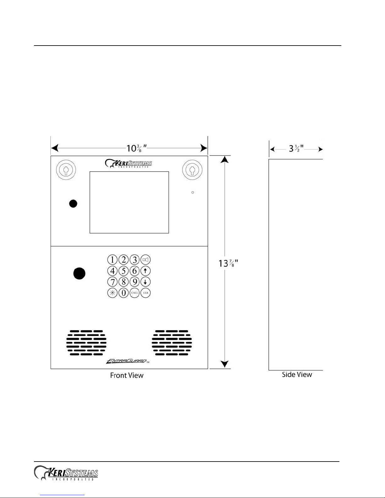
1.1 EntraGuard Platinum Enclosure
Figure 1: The EntraGuard Platinum Telephone Entry Controller
Wiring diagrams are provided for the new style Platinum controller PCB (p/n 05735-001, see Figure 3 on page 3) and old
style Platinum controller PCB (p/n 05728-001, see Figure 4 on page 4).
NOTE: Power down the unit before making or removing any connections. Failure to do so will damage the controller.
NOTE: Please refer to the Compatibility_Guide_Series_3_and_4.pdf document (p/n 01876-001) for Doors software/
Entraguard firmware compatibility.
Page 1 of 10 P/N: 01553-001 Rev. D
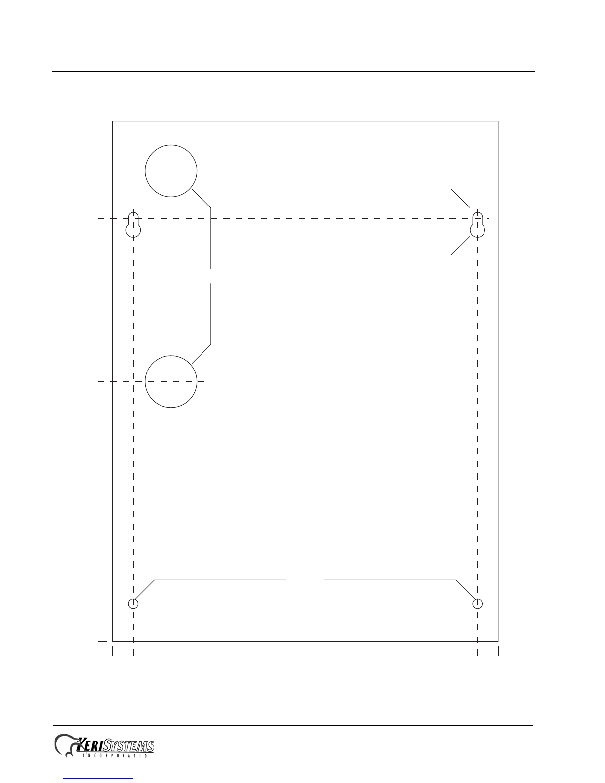
0.00
0.552
1.553
9.686
10.235
0.00
1.001
6.892
10.888
11.223
12.48
13.808
all units in inches
0.256 dia
1.374 dia
0.386 dia
0.258 dia
EntraGuard® Platinum Telephone Entry Controller
Installation Guide
1.2 Enclosure Mounting Diagram
Figure 2: Entraguard Platinum Mounting Diagram
Page 2 of 10 P/N: 01553-001 Rev. D
EntraGuard® Platinum Telephone Entry Controller
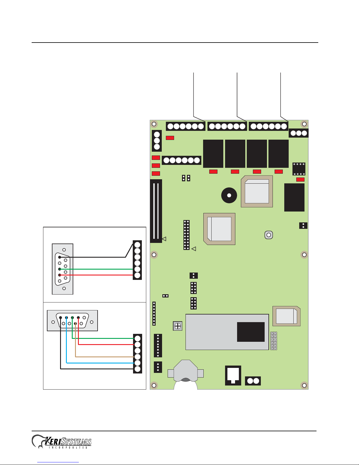
Alarm
Relay
Lock
Relay
GP
Output
Relay 2
GP
Output
Relay 1
6 5 4 3 2 1 6 5 4 3 2 1 6 5 4 3 2 1
3
2
1
6 5 4 3 2 1
1 2 3
2 1
485
U18
U2
Battery
D4
D5
D6
D20 D18
D30
D29
D25
D32
SW1
R75
J3
J1
J6
J8
Internal
Modem
J11
J16 - Postal Lock Connection
JP1
JP2
J19J20
LED Backlight
Connection
J13
U5
J9
TB15
TB1
TB2
TB3TB4 TB10
TB12
1) Door Switch - NC
2) Ground
3) Request to Exit - NO
4) - not available-
5) Ground
6) Global Unlock - NO
or Auxiliary RTE - NO
TB4 - Inputs
1) Lock - NO
2) Lock - Common
3) Lock - NC
4) Alarm - NO
5) Alarm - Common
6) Alarm - NC
TB3 - Lock &
Alarm Relays
1) GP1 - NO
2) GP1 - Common
3) GP1 - NC
4) GP2 - NO
5) GP2 - Common
6) GP2 - NC
TB10- General
Purpose Outputs
1) Tx/Rx -
2) Tx/Rx +
3) Shield
TB1 - RS-485
Network
1) +12 VDC
2) Negative (Ground)
3) Earth Ground
TB2 - 12 VDC Power
TB15 - Wired Telephone Connection
1) TIP2) Ring
J9 - Standard Phone Jack Connection
U39
J10
LAN
Communication
Jumpers
Modem Module
RxD
DTR
TxD
TB12 - RS-232 Serial Port Connection
Pin 3 (RxD) to Pin 1 (TxD)
Pin 2 (TxD) to Pin 2 (RxD)
Pin 7 (RTS) to Pin 4 (RTS)
Pin 4 (DTR) to Pin 5 (DTR)
Pin 5 (Gnd) to Pin 6 (Gnd)
Modem Side DB-9M
(back side of connector)
6
5
4
3
2
1
TB12 - Modem Connection
2345
7
1
2
3
4
5
6
Pin 2 (RxD) to Pin 1 (TxD)
Pin 3 (TxD) to Pin 2 (RxD)
Pin 5 (Gnd) to Pin 6 (Gnd)
2
3
5
PC Side DB-9F
(back side of connector)
TB12 - Direct to PC Connection
Keri p/n: KDP-552
Keri p/n: KDP-929M
J7
LAN-520
Connection
Installation Guide
1.3 New S tyle Platinum Controller
Figure 3: New Style Entraguard Platinum Controller – p/n 05735-001
Page 3 of 10 P/N: 01553-001 Rev. D
 Loading...