

Page 1
Amulet 5
mediA RecoRdeR
Quick Start Guide
Page 2

Table of Contents
OVERVIEW
2 Safety Instructions
4 What’s Included
6 Front Panel
7 Top and Side Panels
8 Rear Panel
CONNECTING VIDEO
9 High-Denition TVs
11 Standard-Denition TVs
CONNECTING AUDIO
13 Stereo
14 Surround Sound
QUICK START GUIDEAMULET MEDIA RECORDER
COPYRIGHT
©2013 Entone, Inc. All rights reserved. This document contains proprietary information protected by
copyright. No part of this publication may be reproduced, stored in a retrieval system, or transmitted in
any form or by any means, electronic, mechanical, photocopying, recording or otherwise, without the
prior written consent of Entone, Inc., 20863 Stevens Creek Blvd, Suite 300, Cupertino, CA 95014, U.S.A.
DISCLAIMER
IF THIS PRODUCT DIRECTS YOU TO COPY MATERIALS, YOU MUST HAVE PERMISSION FROM THE COPYRIGHT OWNER OF THE MATERIALS TO AVOID VIOLATING THE LAW WHICH COULD RESULT IN DAMAGES
OR OTHER REMEDIES.
TRADEMARKS
Entone and the tagline “Connecting the Home” are trademarks of Entone, Inc. All other trademarks or
registered trademarks belong to their respective owners.
This item incorporates copy protection technology that is protected by U.S. patents and other intellectual property rights of Rovi Corporation. Reverse engineering and disassembly are prohibited.
CHANGES
The material in this document is for information only and is subject to change without notice. While reasonable eorts have been made in the preparation of this document to assure its accuracy, Entone, Inc.
assumes no liability resulting from the use of the information contained herein. Entone, Inc. reserves the
right to make changes in the product design without reservation and without notication to its users.
P/N: 99-708004-11 - V2.0
CONNECTING TV SOURCE
15 Cable or Antenna
16 CableCARD
CONNECTING NETWORK
17 Wireless or Wired
POWERING UP
18 Setting Up Remote Control
19 Installing/Uninstalling USM Drive
21 Connecting to Power Source
22 Declaration of Conformity
1
Page 3

Important Safety Instructions
Important Safety Instructions (Continued)
QUICK START GUIDE
• WARNING: To reduce the risk of re or electric shock, do not expose this apparatus to rain or moisture.
• The apparatus shall not be exposed to dripping or splashing and that no objects lled with liquids, such as vases, shall be placed on the apparatus.
• Read these instructions.
• Keep these instructions.
• Heed all warnings.
• Follow all instructions.
• Do not use this apparatus near water.
• Clean only with dry cloth.
• Do not block any ventilation openings. Install in accordance with the manu-
facturer’s instructions.
• Do not defeat the safety purpose of the polarized or grounding-type plug. A
polarized plug has two blades with one wider than the other. A grounding
type plug has two blades and a third grounding prong. The wide blade or the
third prongs are provided for your safety. If the provided plug does not t into
your outlet, consult an electrician for replacement of the obsolete outlet.
• Protect the power cord from being walked on or pinched particularly at plugs,
convenience receptacles, and the point where they exit from the apparatus.
• Only use attachments/accessories specied by the manufacturer.
• Unplug this apparatus during lightning storms or when unused for long peri-
ods of time.
• Refer all servicing to qualied service personnel. Servicing is required when
the apparatus has been damaged in any way, such as power-supply cord or
plug is damaged, liquid has been spilled or objects have fallen into the apparatus, the apparatus has been exposed to rain or moisture, does not operate
normally, or has been dropped.
• To reduce the risk of electric shock, DO NOT remove cover or back panel. No
user serviceable parts inside. Refer servicing to qualied personnel.
• To help prevent electric shock, plug the power cable into properly grounded
sources. Use only properly grounded extension cords and adaptors, if they are
needed.
• The AC main plug is used as the disconnect device, the disconnect device shall
remain readily operable.
• Make sure nothing is lying on any of the cables.
• Be sure the cables are located where they will not be stepped on or tripped
over.
• Do not spill food or liquids onto the unit.
• Do not push any objects into the free slots. Doing so will damage the unit, can
cause re or electrical shock, and can short out interior components.
• Do not install near any heat sources such as radiators, heat registers, stoves, or
other apparatus (including ampliers) that produce heat.
• Do not block cooling vents.
• Do not place the equipment in a closed-in wall unit.
• When you disconnect a cable, pull on its connector or on its strain relief loop,
not on the cable itself. Some cables have a connector with locking tabs; if
you are disconnecting this type of cable, press in on the locking tabs before
disconnecting the cables.
• When you connect a cable, make sure both connectors are correctly oriented
and aligned before connecting to avoid bending connector pins.
• For PLUGGABLE EQUIPMENT, the socket-outlet should be installed near the
equipment for easy access.
• Changes or modications not expressly approved by the party responsible
could void the user’s authority to operate this device.
QUICK START GUIDE
AMULET MEDIA RECORDER
AMULET MEDIA RECORDER
32
Page 4
QUICK START GUIDE
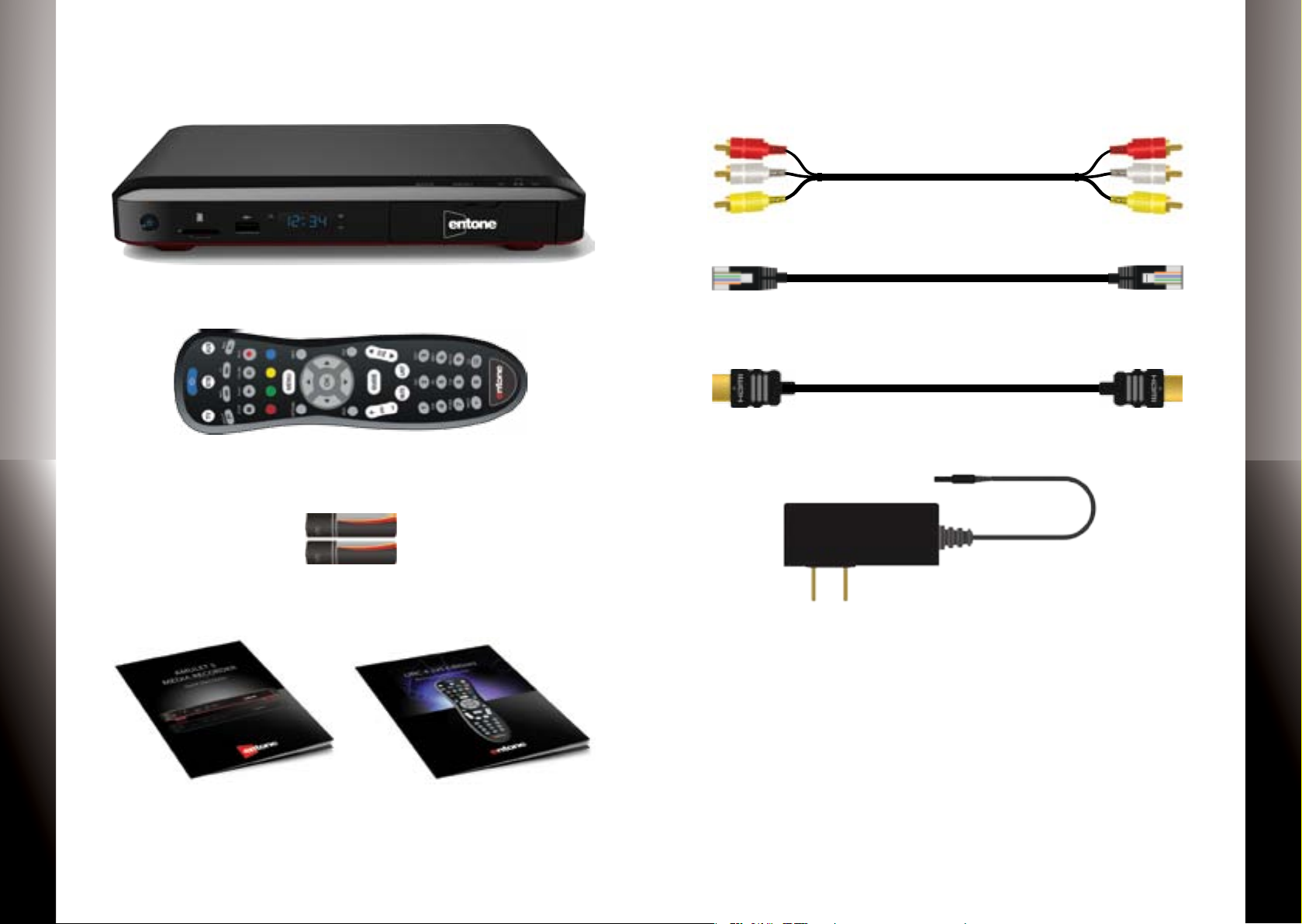
What’s Included
Composite Audio/Video Cable
AMULET MEDIA RECORDER
Amulet Media Recorder
IR Remote Control*
2 Batteries for
Remote Control
Amulet Quick Start Guide Remote Control Guide
Ethernet Cable (Optional)
HDMI Cable (Optional)
AC Power Adapter
Additional items that may be required (not included):
• Ethernet Cable
• Component Video Cable
• HDMI Cable
• RF Coaxial Cable
• Digital Audio Cable
• Network Router
• Multi-stream CableCARD (M-Card)
QUICK START GUIDE
AMULET MEDIA RECORDER
*The Remote Control may vary on your service provider.
54
Page 5
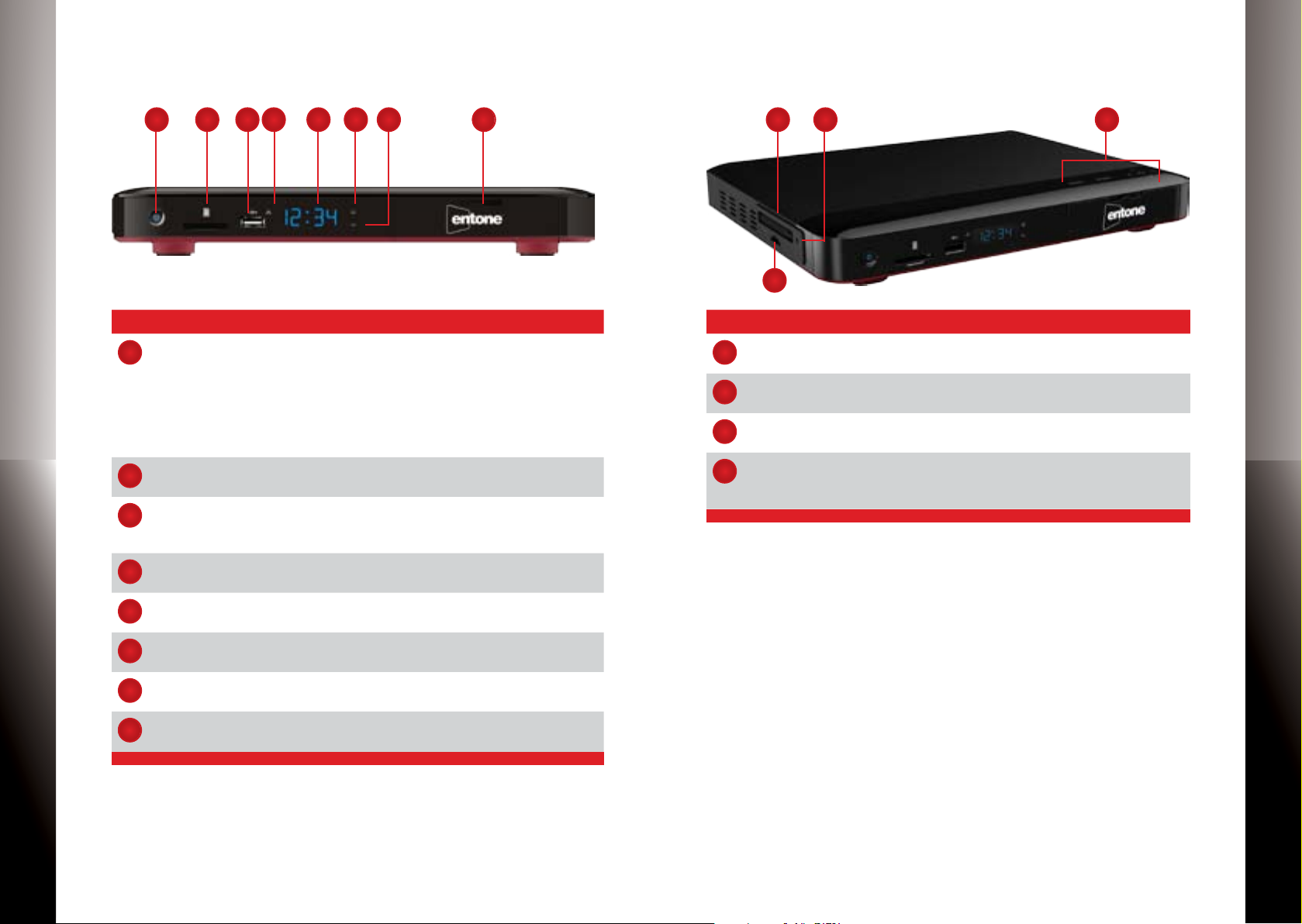
Amulet — Front Panel
8
8
Amulet — Top and Side Panels
QUICK START GUIDE
AMULET MEDIA RECORDER
4
1
Name Description
Power Solid blue indicates the unit is on.
1
SD Card Reader To read or transfer content from a compatible SD ash
2
USB To connect USB devices such as USB ash drive and
3
Link Indicator Blue dot indicates that Ethernet or Wi-Fi network con-
4
Clock Displays current time set by your service provider. May
5
Record Indicator Blue dot indicates a TV program is currently recording.
6
HD Indicator Blue dot indicates current program is playing in HD
7
USM Port For inserting a universal storage module (USM) hard
3
2
5
6
7
Solid red indicates the unit is in standby mode.
Flashing blue indicates the unit is booting up.
Press button once to put unit in standby mode, press
again to resume.
To reboot the device, press and hold button for at least
5 seconds.
memory card.
external USB hard drive.
(max 500mA load)
nection is active.
not display time while device is booting up.
(720p or higher) resolution.
drive.
2
3
1
Name Description
Smart Card Port* For use with SIM format Smart Card only.
1
CableCARD Port* For use with M-CARD only (provided by your service
2
Eject Pin Hole* For ejecting an M-CARD from the CableCARD port.
3
7-Way Navigation
4
+ MENU*
provider).
Use Back, MENU, OK and Directional buttons to help
with navigating the user interface without a remote
control.
4
QUICK START GUIDE
AMULET MEDIA RECORDER
* Features may vary depending on your service provider. Contact your service
provider for more details.
* Features may vary depending on your service provider. Contact your service
provider for more details.
76
Page 6

Amulet — Rear Panel
STEP 1: CONNECTING VIDEO
QUICK START GUIDE
3
1
2
4
5
7
8
6
Name Description
Cable/ANT In* For connecting to a cable TV or antenna source.
1
TV Out* For connecting to an RF TV for loop-through.
2
Composite Video For connecting to a standard-denition TV (SDTV).
3
Audio Stereo audio output (Left / Right).
4
Component
5
Video
IR Blaster Port For connecting to an IR Blaster.
6
(For Amulet 500 series, it should NOT be connected to
in-house cable network)
For connecting to a high-denition TV (HDTV).
9
11
Amulet provides up to four video options for connecting
to your TV: HDMI, Component Video, Composite Video and
Coaxial. Select a video option then proceed to”Connecting
Audio” on page 13.
Make sure your TV is turned on and the correct video input is
selected.
QUICK START GUIDE
10
Option 1: HDMI (Recommended)
If your TV has an HDMI connection,
Delivers the best video & audio
quality via a single cable
use an HDMI cable (may not be included) and connect Amulet to the HDMI IN port on your TV.
This connection provides both video and audio so you do not
need a separate audio connection. Proceed to
“Connecting TV Source” on page 15.
AMULET MEDIA RECORDER
Digital Audio For connecting to an entertainment system that sup-
7
HDMI For connecting to a high-denition TV (HDTV).
8
Ethernet For connecting to a wired network.
9
USB To connect USB devices such as USB ash drive and
10
Power For connecting to a power source (100-240V, Output
11
* Features may vary depending on your service provider. Contact your service
provider for more details.
ports 5.1 Surround Sound audio.
external USB hard drive. (max 500mA load)
12V/3A).
Cable is optional and
may not be included
S-VIDEO
AMULET MEDIA RECORDER
98
Page 7

Option 2: Component Video
Option 3: Composite Video
QUICK START GUIDE
Use a Component cable (not provided) and connect the red/blue/green
Component Video
Delivers excellent picture
quality
cables to the COMPONENT VIDEO IN
port on your TV. Then proceed to the next step (“Connecting
Audio”) to connect the red/white cables.
If you have selected HDMI as your video connection, then do
not use this cable.
Use the Composite cable provided
Composite Video
Delivers good picture quality
and connect the yellow cable to the
yellow VIDEO IN port on your TV.
Then proceed to the next step (“Connecting Audio”) to connect the red/white cables.
If you have selected HDMI as your video connection, then do
not use this cable.
QUICK START GUIDE
AMULET MEDIA RECORDER
Cable not included
S-VIDEO
S-VIDEO
Cable included
AMULET MEDIA RECORDER
1110
Page 8

Option 4: Coaxial (Optional)
STEP 2: CONNECTING AUDIO
QUICK START GUIDE
Use a Coaxial cable (not provided)
Coaxial Cable
Delivers good picture quality
and connect the cable to the ANTENNA IN port on your TV. This connection provides both video and audio so you do not need a
separate audio connection. Proceed to “Connecting TV Source”
on page 15.
NOTE: For Amulet 500 Series, this should not be connected to
the in-house cable network
If you have selected HDMI as your video connection, then do
not use this cable.
NOTE: If you have selected HDMI or Coaxial as your video
connection, then skip this audio section and proceed to “Connecting TV Source” on page 15.
Option 1: Stereo
Use the Composite cable provided and connect the red and
white cables to the Amulet A/V Out port and the red and
white cables to the AUDIO IN port on your TV.
QUICK START GUIDE
AMULET MEDIA RECORDER
Cable not included
ANT IN
S-VIDEO
S-VIDEO
Cable included
AMULET MEDIA RECORDER
1312
Page 9

Option 2: Surround Sound
STEP 3: CONNECTING TV SOURCE OPTIONAL
QUICK START GUIDE
If your TV is connected to an A/V Receiver that supports Dolby
Digital 5.1 Surround Sound, use a digital audio cable (sold
separately) to connect Amulet to the OPTICAL AUDIO IN port
on your A/V Receiver.
Amulet allows you to receive live TV programming from a Cable TV or Antenna source. Select a TV source option below and
connect an RF coaxial cable (sold separately) from the Cable
TV or Antenna.
Option 1: Unencrypted Cable TV
Option 2: Antenna (Indoor or Outdoor)
Option 3: Premium Cable TV with CableCARD
NOTE: If you selected option 1 or 2, then proceed
to”Connecting Network”. If you selected option 3, proceed to
STEP 4: Installing CableCARD.
QUICK START GUIDE
AMULET MEDIA RECORDER
Cable not included
Cable not included
AMULET MEDIA RECORDER
1514
Page 10

STEP 4: INSTALLING CABLECARD OPTIONAL
STEP 5: CONNECTING NETWORK
QUICK START GUIDE
CableCARD is a PCMCIA card that allows access to premium
digital cable programming. CableCARDs are available from
your local cable service provider. It is an optional feature for
Amulet . Contact your service provider for more details.
1. Insert the CableCARD properly into the device.
2. The CableCARD will need to be paired with your cable TV
service. Refer to the instructions from your service provider
for more details on how to pair your CableCARD.
NOTE: The pairing process may take a few minutes or sometimes a few hours depending on your cable service provider.
If you have not received your premium programming in one
hour, please call your service provider for troubleshooting tips.
Select from one of the following networking options.
Option 1: Wireless
Connect your Amulet to a Wireless Network Router or Access
Point.
NOTE: Internal Wi-Fi is an optional feature for Amulet . Contact your service provider for more details and instructions on
how to congure Amulet for your wireless network.
Option 2: Wired
Connect an Ethernet cable (may not be included) from
Amulet to a cable/DSL modem or Network Router.
QUICK START GUIDE
AMULET MEDIA RECORDER
CableCARD not included
Cable is optional and
may not be included
Router not included
AMULET MEDIA RECORDER
1716
Page 11

STEP 6: POWERING UP
Installing USM Drive
QUICK START GUIDE
Setting Up Remote Control
1. Open the battery cover by pressing down on the battery
cover latch and sliding it o.
2. Insert the batteries, matching the “+” and “-” marks on the
batteries with the interior of the remote control.
3. Snap on the battery cover to close.
NOTE: Refer to the Remote Control Guide for more details
about other remote control features.
Amulet provides an integrated Universal Storage Module
(USM) port for DVR applications. You can easily install, upgrade
or replace a compatible USM drive.
1. Open the USM ap located on front panel of the Amulet .
2. Insert the USM drive into the port.
NOTE: For security purposes, the USM port may be locked by
your service provider. Contact your service provider for more
details.
QUICK START GUIDE
AMULET MEDIA RECORDER
AMULET MEDIA RECORDER
1918
Page 12

Uninstalling USM Drive
Connecting to Power Source
QUICK START GUIDE
1. To safely eject the USM drive, push the release lever located on the bottom of the Amulet.
2. Remove the USM drive from the port and close the front
panel ap.
NOTE: For security purposes, the USM port may be locked by
your service provider. Contact your service provider for more
details.
1. Connect the power cord to the POWER port on the back of
the Amulet .
2. Plug the AC power adapter to a power outlet.
3. Follow the on-screen instructions.
NOTE: Make sure your TV is turned on and the correct video
input is selected.
QUICK START GUIDE
AMULET MEDIA RECORDER
AMULET MEDIA RECORDER
2120
Page 13

Declaration of Conformity
Declaration of Conformity (Continued)
QUICK START GUIDE
To ensure proper use of this product, please read this manual carefully and retain it for future reference. Should the unit require maintenance, contact an authorized service location.
WARNING: This symbol indicates the presence of uninsulated dangerous voltage within the
product’s enclosure that constitutes a risk of electric shock. Do not open the product’s case.
CAUTION: This symbol indicates you must take care; there is risk of damage to the equipment or to yourself.
Declaration of Conformity (Europe Only)
This product is in conformity with the Council Directives:
•EMCDirective2004/108/EC
•LowvoltageDirective2006/95/EC
Industry Canada statement:
This device complies with RSS-210 of the Industry Canada Rules. Operation is subject to
the following two conditions: (1) This device may not cause harmful interference, and (2)
this device must accept any interference received, including interference that may cause
undesired operation.
Ce dispositif est conforme à la norme CNR-210 d’Industrie Canada applicable aux appareils
radio exempts de licence. Son fonctionnement est sujet aux deux conditions suivantes:
(1) le dispositif ne doit pas produire de brouillage préjudiciable, et (2) ce dispositif doit
accepter tout brouillage reçu, y compris un brouillage susceptible de provoquer un fonctionnement indésirable.
Radiation Exposure Statement:
This equipment complies with IC radiation exposure limits set forth for an uncontrolled
environment. This equipment should be installed and operated with minimum distance
20cm between the radiator & your body.
Déclaration d’exposition aux radiations:
Cet équipement est conforme aux limites d’exposition aux rayonnements IC établies pour
un environnement non contrôlé. Cet équipement doit être installé et utilisé avec un minimum de 20 cm de distance entre la source de rayonnement et votre corps.
To prevent re or shock hazard, do not expose this product to rain or moisture. To reduce
the risk of electric shock, DO NOT remove the cover or back. No user serviceable parts are
inside. For servicing refer to qualied personnel.
Declaration of Conformity (United States Only)
This device complies with Part 15 of the FCC Rules. Operation is subject to the following
conditions: (1) this device may not cause harmful interference, and (2) this device must
accept any interference received, including interference that may cause undesired operation. This equipment has been tested and found to comply with the limits for a Class B
digital device, pursuant to Part 15 of the Federal Communication Commission (FCC) Rules.
These limits are designed to provide reasonable protection against harmful interference in
a residential installation. This equipment generates, uses, and can radiate radio frequency
energy, and if not installed and used in accordance with the instructions, may cause harmful interference to radio communications. However, there is no guarantee that interference
will not occur in a particular installation. If this equipment does cause harmful interference
to radio or television reception, which can be determined by turning the equipment OFF
and ON, the user is encouraged to try to correct the interference by one or more of the
following measures:
•Reorientorrelocatethereceivingantenna.
•Increasetheseparationbetweentheequipmentandthereceiver.
•Connecttheequipmenttoadierentcircuitfromthattowhichthereceiveriscon-
nected.
•Consultthedealeroranexperiencedradio/TVtechnicianforhelp.
FCC Caution: Any changes or modications not expressly approved by the party responsible for compliance could void the user’s authority to operate this equipment.
This transmitter must not be co-located or operating in conjunction with any other antenna
or transmitter.
Radiation Exposure Statement:
This equipment complies with FCC radiation exposure limits set forth for an uncontrolled
environment. This equipment should be installed and operated with minimum distance
20cm between the radiator & your body.
QUICK START GUIDE
AMULET MEDIA RECORDER
AMULET MEDIA RECORDER
2322
Page 14

QUICK START GUIDE
Notes
QUICK START GUIDE
AMULET MEDIA RECORDER
AMULET MEDIA RECORDER
2524
Page 15

©2013 Entone, Inc. Entone, Amulet and connecting the home are trademarks of Entone, Inc. Other company, product, and service names
may be trademarks or service marks of others. All information contained in this document is subject to change without notice. Information
contained in this document is provided on an as is basis. In no event will Entone be liable for damages arising directly or indirectly from any
use of the information contained in this document. Subject to change without notice.
 Loading...