

Page 1

1
SMART FOR YOUR HOME
INSTALLATION
MANUAL
Page 2

2
INSTALATION MANUAL
Page 3

3
Lighting
On/Off
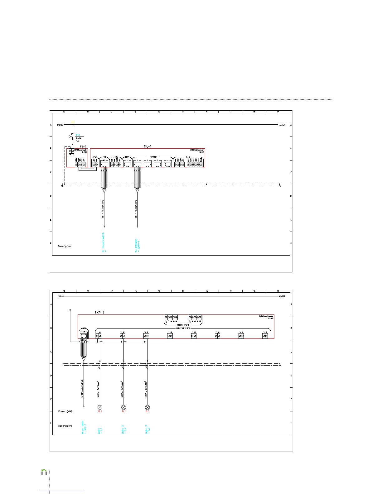
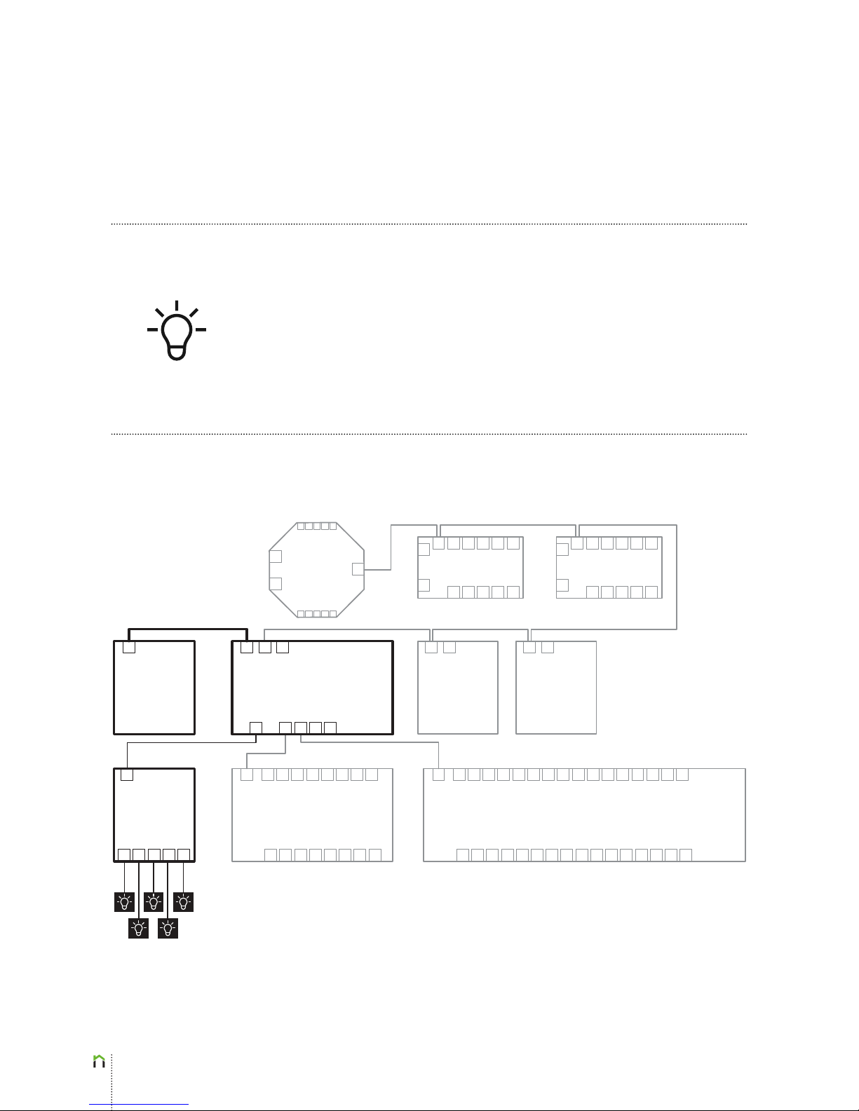
On/off lights (and other on/off devices) have to be connected to the ENTIAliving system
as shown in the block diagram below. Note that on/off lights can be connected to either,
Power Expander EL-E1801 or Power Expander EL-E1601 (the former being depicted in the
block diagram below). One EL-E801 Power Expander supports up to 8 power outputs,
while EL-E1601 Power Expander supports up to 16 power outputs. Dimmed lights must
be connected to the Power Dimmer EL-D01 instead of Power Expander modules as shown
later on in this document. Note that on the block diagram below, the elements and wiring
for lighting connection is highlighted.
Sens
Controller
EL-S01
Room Controller
EL-R02
DALI Converter
EL-CD01
Power Dimmer
EL-D01
MODBUS
Converter
EL-CA01
Power Supply
EL-PS01
Main Controller EL-M01
Power Expander EL-E801
Lights 1-5
Power Expander EL-E1601
Room Controller
EL-R02
2x1.5
2x0.75
SFTP
3 x 1.5
2 x 0.75
Page 4
4
Lighting
On/Off
Page 5
5
Lighting
Dimm
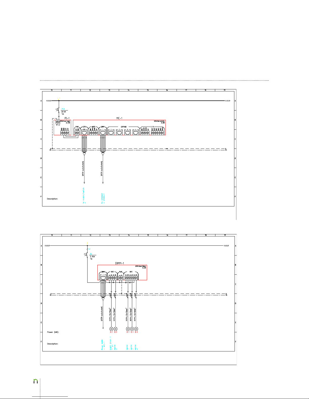
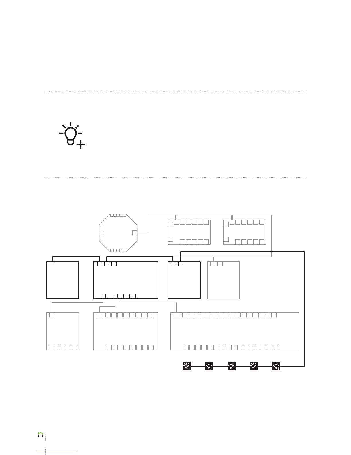
Dimmable lights have to be connected to the ENTIAliving system as shown in the block
diagram below. Note that dimmable lights can be connected to Power Dimmer EL-D01. One
EL-D01 Power Dimmer supports up to 5 dimmer outputs. Note that on the block diagram
below, the elements and wiring for lighting connection is highlighted.
Sens
Controller
EL-S01
Room Controller
EL-R02
DALI Converter
EL-CD01
Power Dimmer
EL-D01
MODBUS
Converter
EL-CA01
Power Supply
EL-PS01
Main Controller EL-M01
Power Expander EL-E801
Lights 1-5
Power Expander EL-E1601
Room Controller
EL-R02
2x1.5
2x0.75
SFTP
3 x 1.5
2 x 0.75
Page 6
6
Lighting
Dimm
Page 7
7
Lighting
DALI
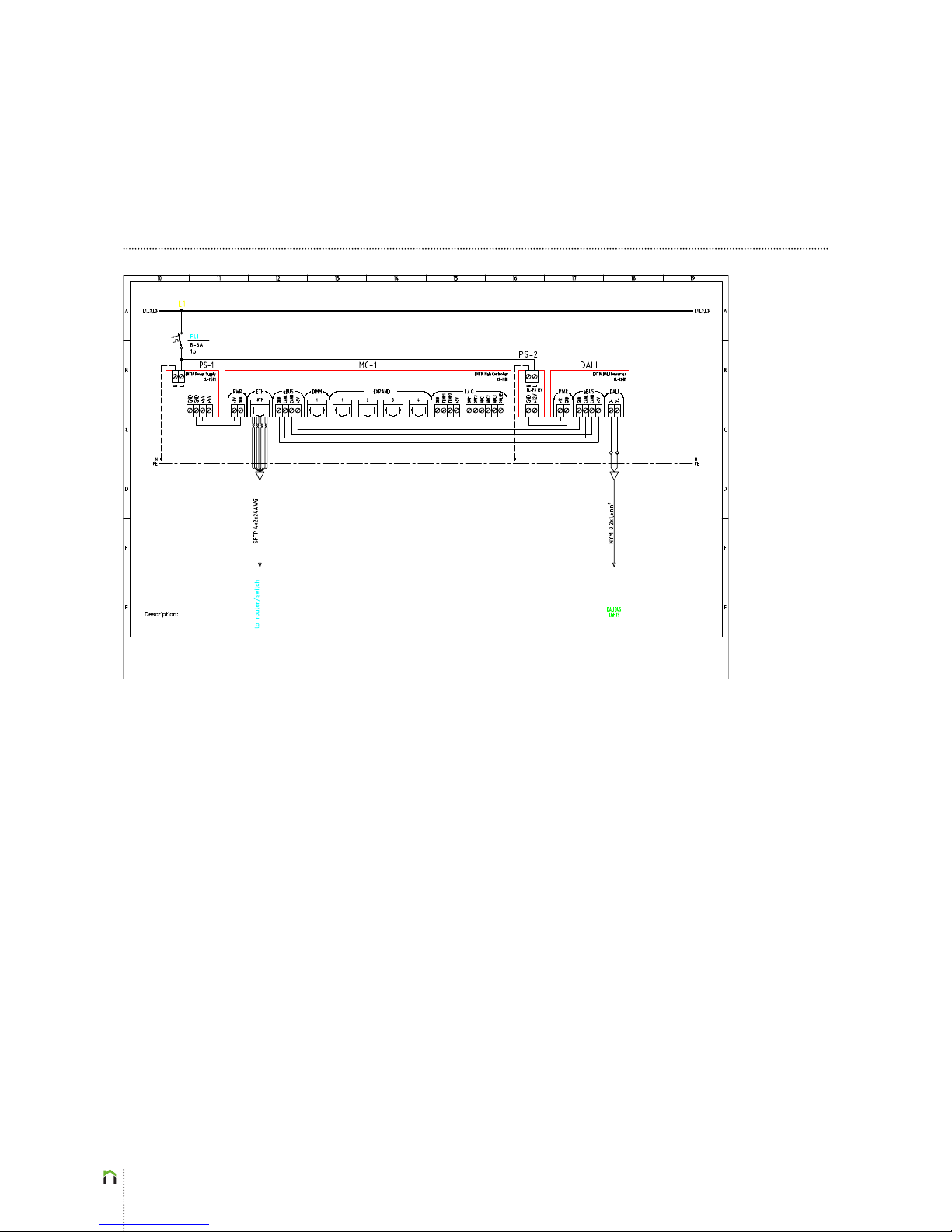
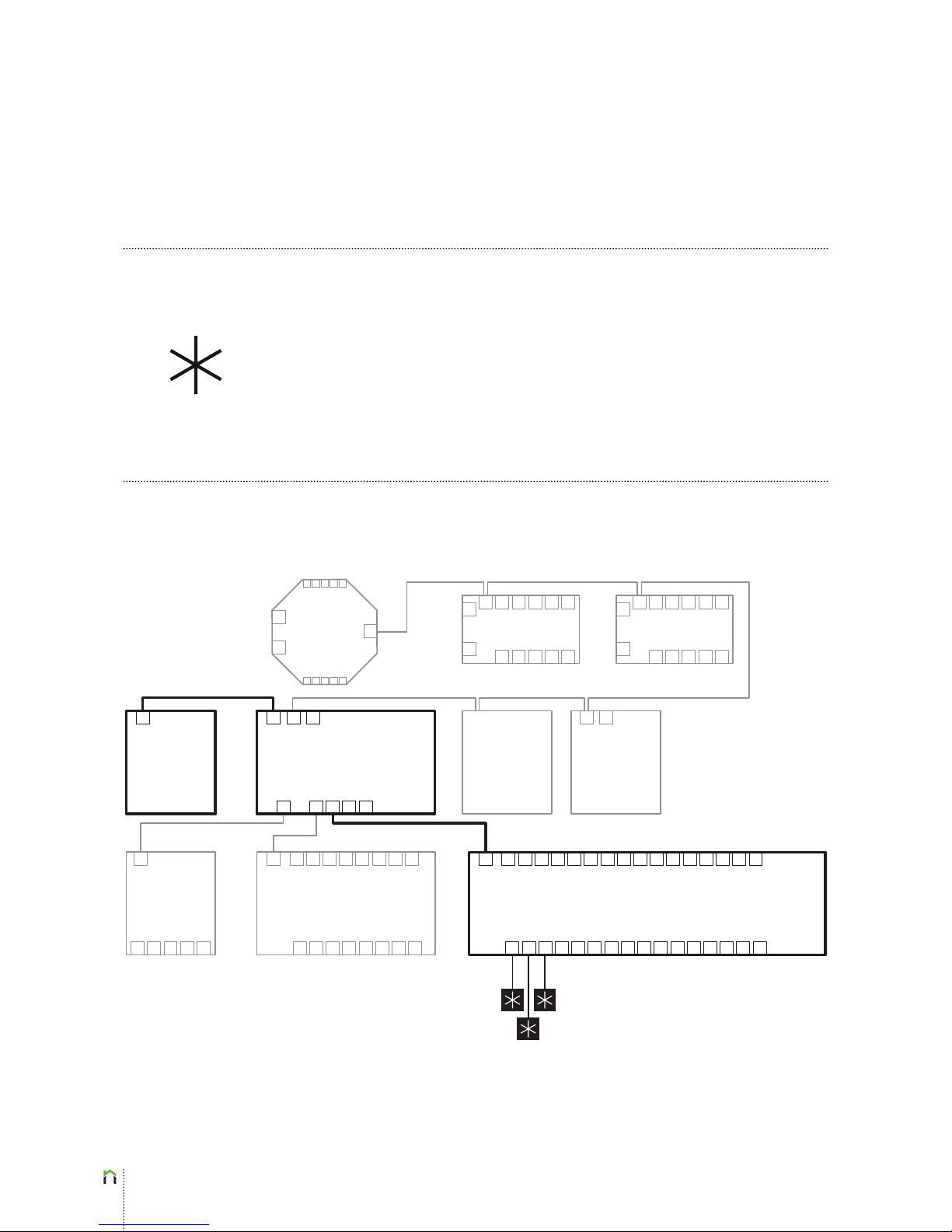
DALI lighting devices have to be connected to the ENTIAliving system as shown in the block
diagram below. Note that one ENTIAliving DALI Converter EL-CD01 can support up to 64
DALI lighting devices and 16 groups of DALI lighting devices. On the block diagram below,
the elements and wiring for DALI lighting connection is highlighted.
Sens
Controller
EL-S01
Room Controller
EL-R02
DALI Converter
EL-CD01
Power Dimmer
EL-D01
MODBUS
Converter
EL-CA01
Power Supply
EL-PS01
Main Controller EL-M01
Power Expander EL-E801
DALI
Light 1
DALI
Light 4
Dimm
Light 2
Dimm
Light 3
Dimm
Light 5
Power Expander EL-E1601
Room Controller
EL-R02
2x0.75
eBUS (CAN) J(Y)-ST-Y
2 x 2 x 0,8 J(Y)-STY
DALI BUS
Page 8
8
Lighting
DALI
Page 9
9
Heating&Cooling
Valves
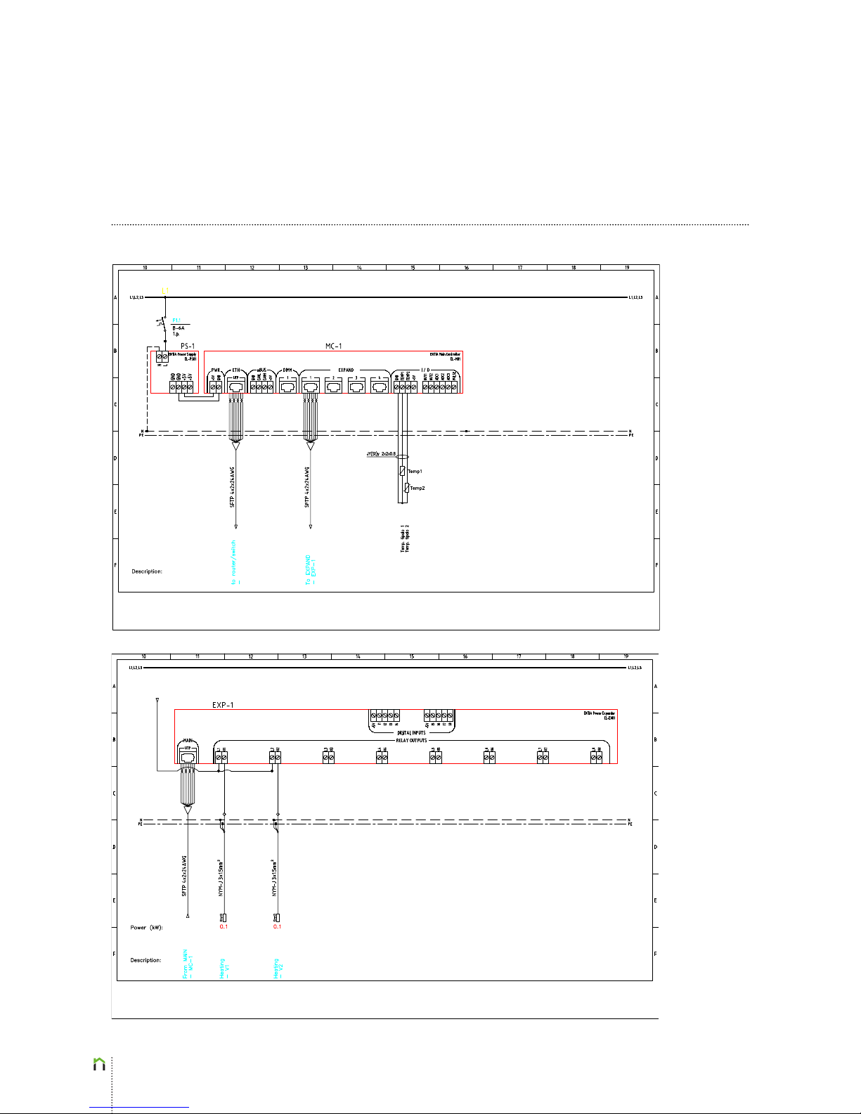
On/off heating valves (and other on/off devices) need to be connected to the ENTIAliving
system as shown in the block diagram below. Note that described devices can be connected
to either Power Expander EL-E801 or Power Expander EL-E1601 (the latter being depicted in
the block diagram below). One EL-E801 Power Expander supports up to 8 power outputs,
whereas EL-E1601 Power Expander supports up to 16 power outputs. Note that on the
block diagram below, the elements and wiring for heating valve connection is highlighted.
Sens
Controller
EL-S01
Room Controller
EL-R02
DALI Converter
EL-CD01
Power Dimmer
EL-D01
MODBUS
Converter
EL-CA01
Power Supply
EL-PS01
Main Controller EL-M01
Power Expander EL-E801 Power Expander EL-E1601
Room Controller
EL-R02
SFTP
Bathroom / Bedroom 1-2
2 x 0.75
3 x 1,5
Page 10
10
Heating&Cooling
Valves
Page 11
11
Heating&Cooling
Fan-Coils
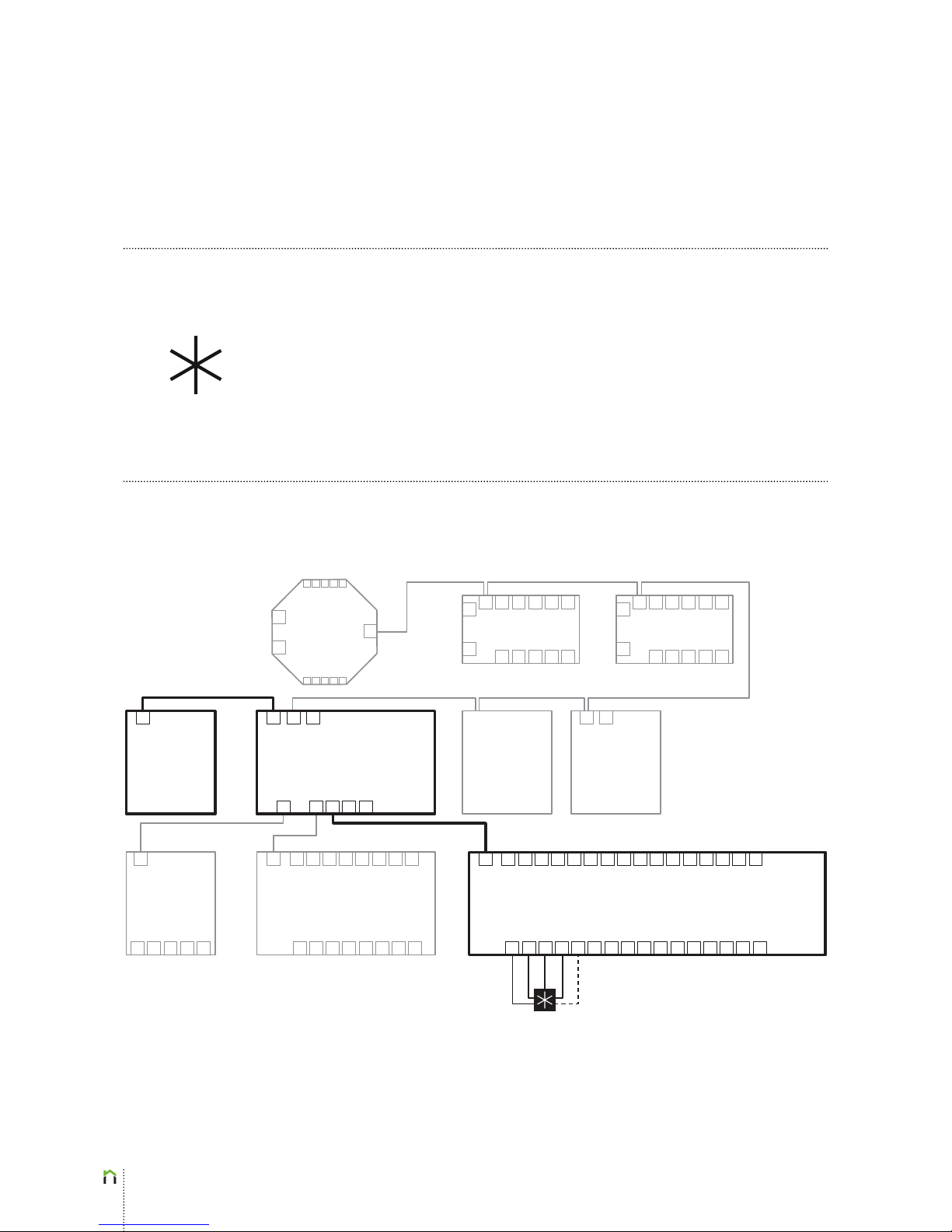
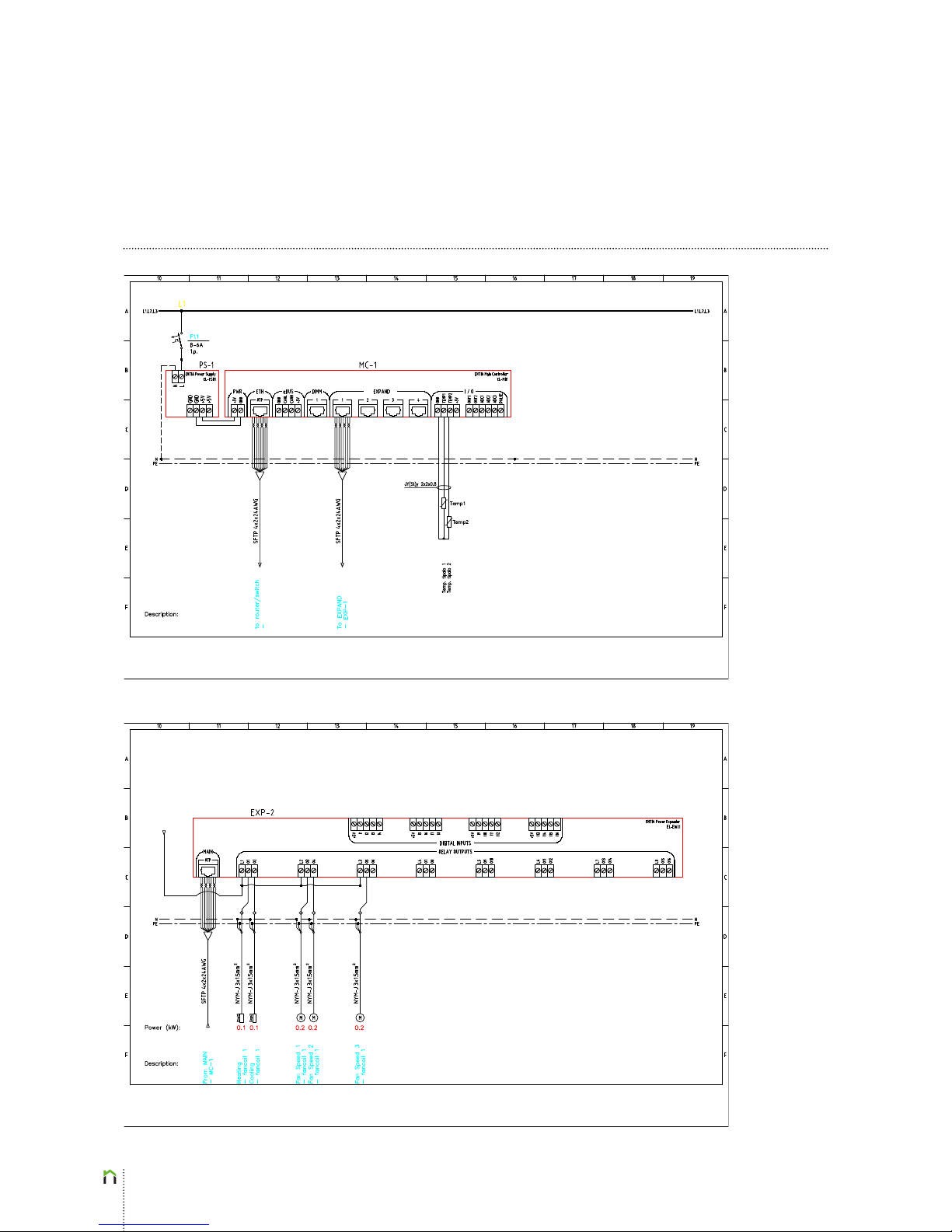
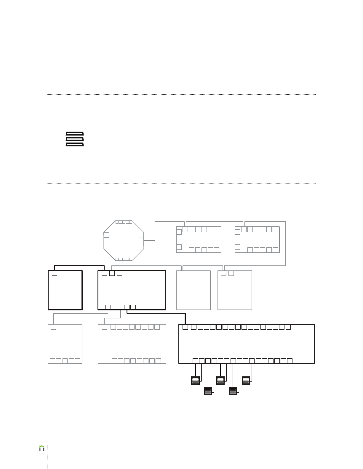
Fan coils need to be connected to the ENTIAliving system as shown in the block diagram
below—the dashed line is connected in case of a 2 tube system (same tubes for hot and
cold water), while it is not connected in a 4 tube system. Note that described HVAC devices
can be connected to either Power Expander EL-E1801 or Power Expander EL-E1601 (the
latter being depicted in the block diagram below). One EL-E801 Power Expander supports
up to 8 power outputs, whereas EL-E1601 Power Expander supports up to 16 power outputs.
Note that on the block diagram below, the elements and wiring for fancoil connection is
highlighted.
Sens
Controller
EL-S01
Room Controller
EL-R02
DALI Converter
EL-CD01
Power Dimmer
EL-D01
MODBUS
Converter
EL-CA01
Power Supply
EL-PS01
Main Controller EL-M01
Power Expander EL-E801 Power Expander EL-E1601
Room Controller
EL-R02
SFTP
2x0.75
4 (5) x 1,5
Page 12
12
Heating&Cooling
Fan-Coils
Page 13
13
Shading
Shades, Blinds,...
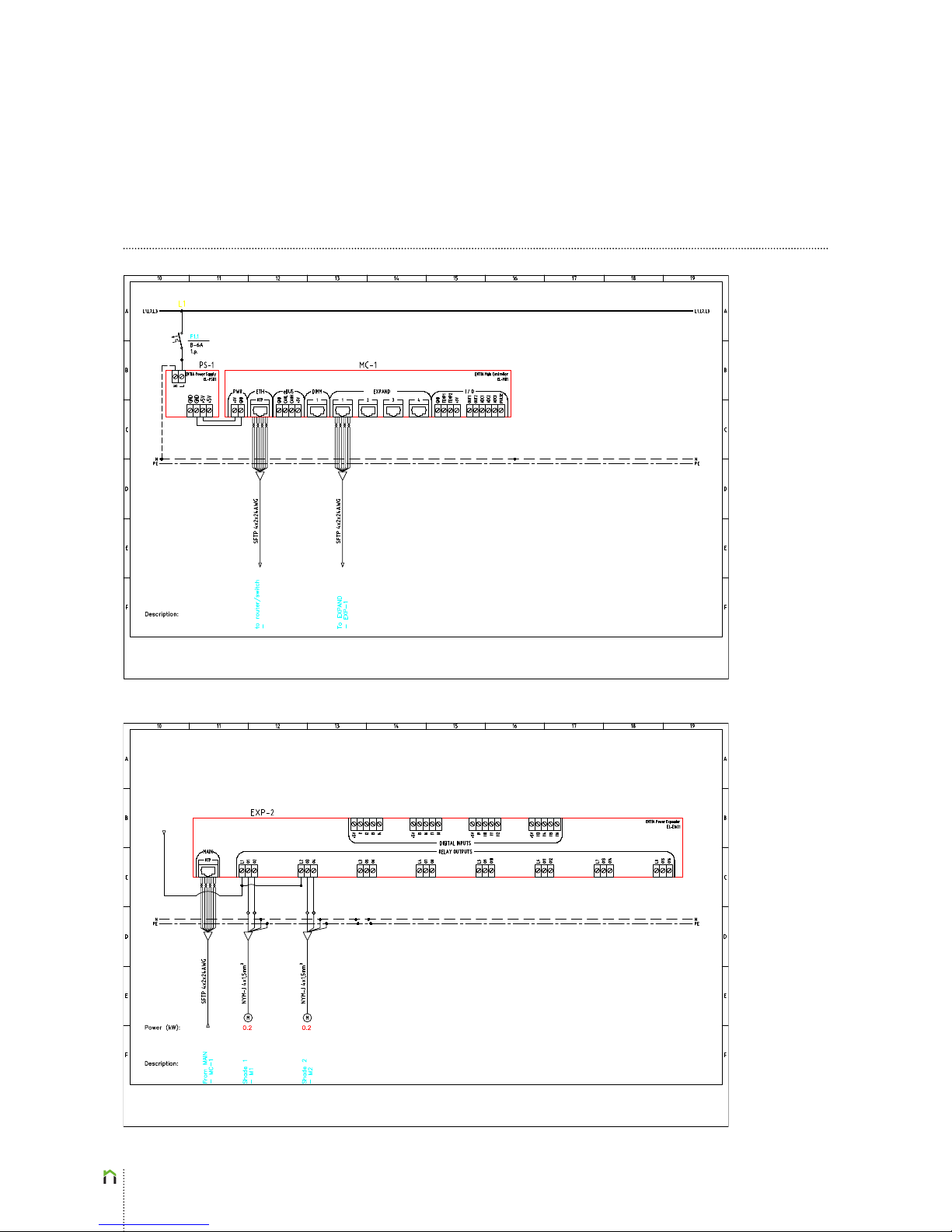
Shading devices, such as shades, blinds, tendas and other have to be connected to the
ENTIAliving system as shown in the block diagram below. As opposed to lighting installation
(previous chapter), shading MUST NOT be connected to the ENTIAliving Power Expander
EL-E801 and must instead be connected to the Power Expander EL-E1601. Note that on
the block diagram below, the elements and wiring for shading connection is highlighted.
Sens
Controller
EL-S01
Room Controller
EL-R02
DALI Converter
EL-CD01
Power Dimmer
EL-D01
MODBUS
Converter
EL-CA01
Power Supply
EL-PS01
Main Controller EL-M01
Power Expander EL-E801 Power Expander EL-E1601
Room Controller
EL-R02
STP
2x0.75
Shade 1-5
4 x 1,5
Page 14
14
Shading
Shades, Blinds, ...
Page 15
15
Air Conditioning
IR
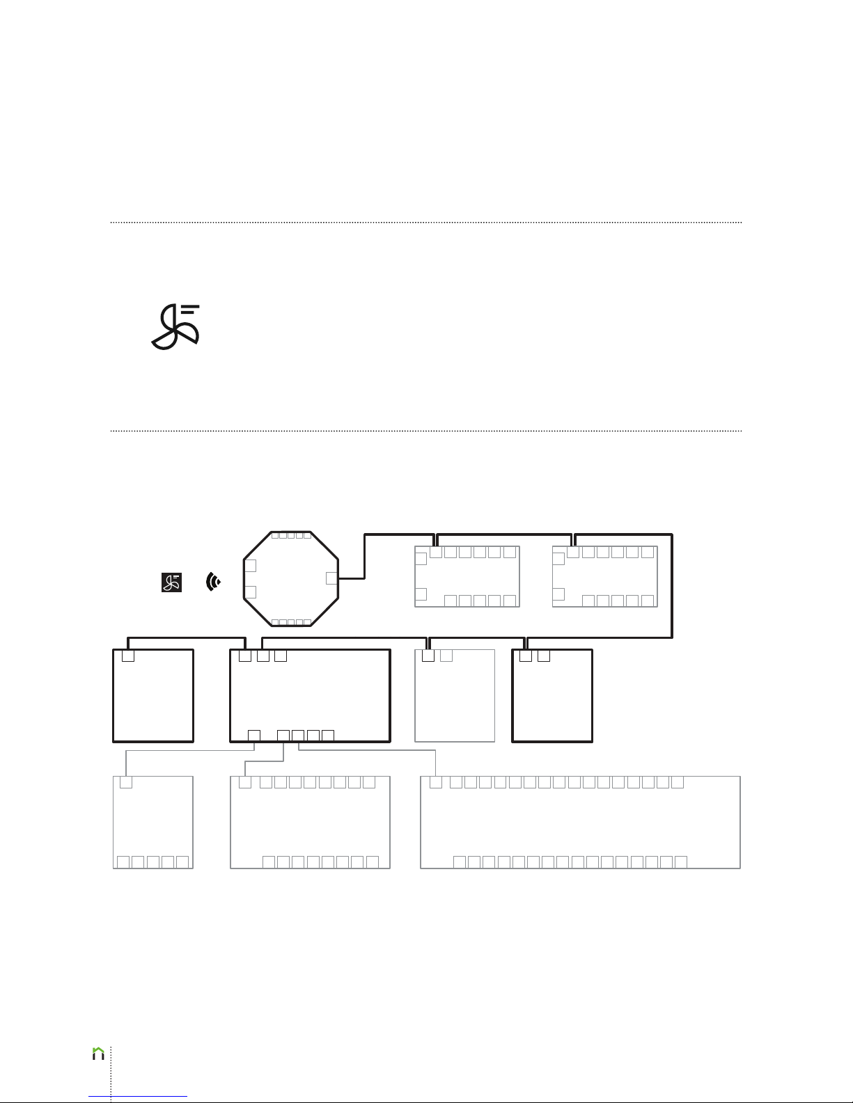
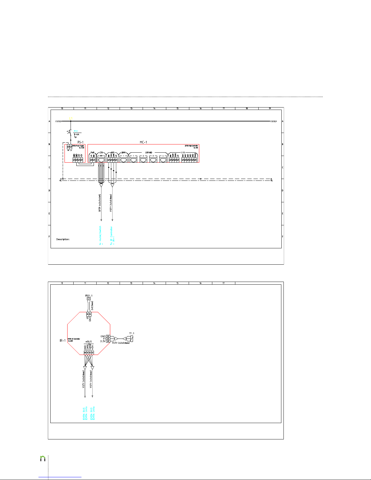
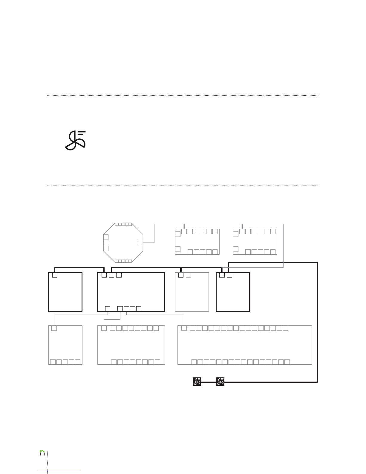
Any IR remote controlled A/C device can be connected to the ENTIAliving system as shown
in the block diagram below. Note that one ENTIAliving IR Controller EL-IR01 can support
1 air conditioning device. On the block diagram below, the elements and wiring for air
conditioning connection is highlighted.
IR
Controller
EL-IR01
Room Controller
EL-R02
DALI Converter
EL-CD01
Power Dimmer
EL-D01
MODBUS
Converter
EL-CA01
Power Supply
EL-PS01
Main Controller EL-M01
Power Expander EL-E801
A/C 1
Power Expander EL-E1601
Room Controller
EL-R02
2x0.75
eBUS (CAN) J(Y)-ST-Y
2 x 2 x 0,8 J(Y)-STY 2 x 2 x 0,8 J(Y)-STY2 x 2 x 0,8 J(Y)-STY
Page 16
16
Air Conditioning
IR
Page 17
17
Air Conditioning
MODBUS
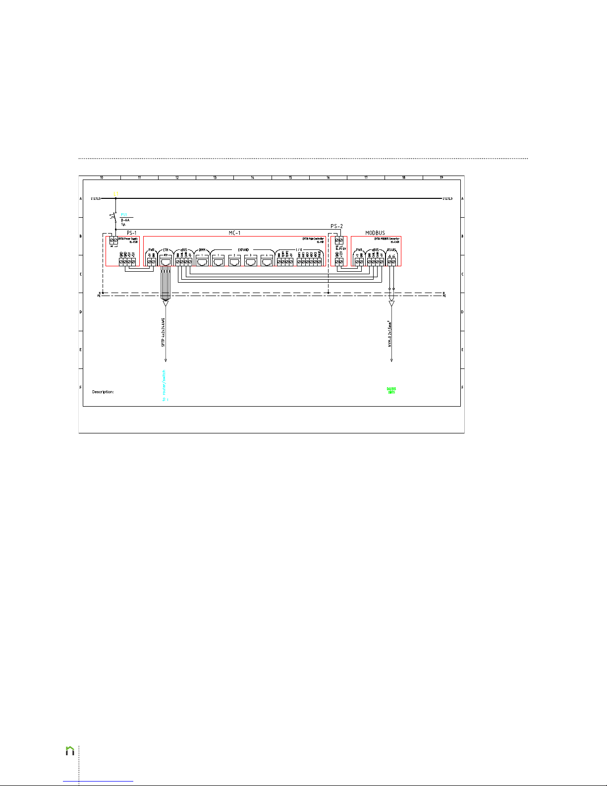
MODBUS compatible A/C devices have to be connected to the ENTIAliving system as shown
in the block diagram below. Note that one ENTIAliving MODBUS Converter EL-CA01 can
support up to 256 air conditioning devices. On the block diagram below, the elements and
wiring for air conditioning connection is highlighted.
Sens
Controller
EL-S01
Room Controller
EL-R02
DALI Converter
EL-CD01
Power Dimmer
EL-D01
MODBUS
Converter
EL-CA01
Power Supply
EL-PS01
Main Controller EL-M01
Power Expander EL-E801
A/C 2A/C 1
Power Expander EL-E1601
Room Controller
EL-R02
2x0.75
eBUS (CAN) J(Y)-ST-Y
2 x 2 x 0,8 J(Y)-STY
2 x 2 x 0,8 J(Y)-STY
Page 18
18
Air Conditioning
MODBUS
Page 19
19
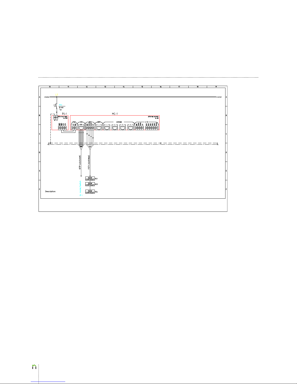
CAN
Units
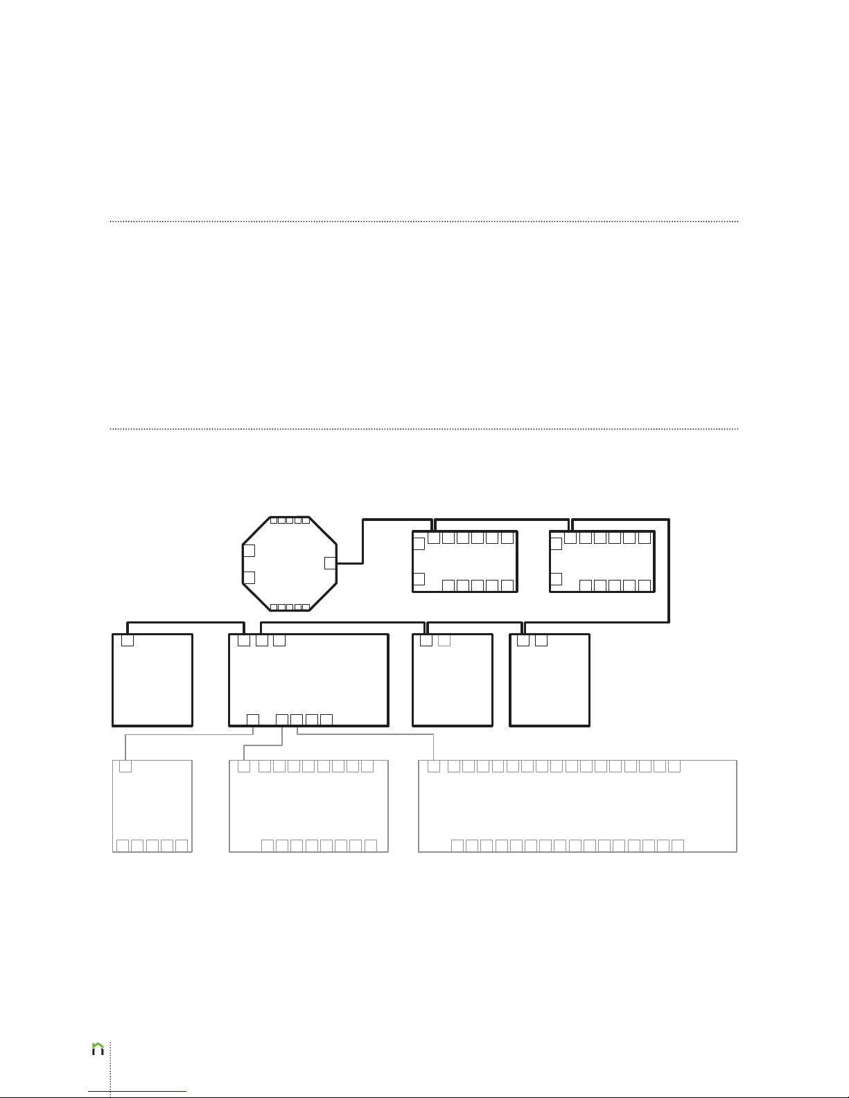
ENTIAliving CAN (eBUS) controllers, such as Main Controller EL-M01, Main Controller EL-M01a,
Room Controller EL-R02, DALI Converter EL-CD01, MODBUS Converter EL-CA01 and Sens
Controller EL-S01 have to be connected as shown in the block diagram below. Note that on
the block diagram below, the CAN elements and wiring is highlighted. The order in which
CAN devices are interconnected is of no consequence (e.g. we could start with a Room
Controller instead of the Main Controller). Multiple Main Controllers can be connected in
one eBUS circuit, if required (e.g. in case of more than 64 power outputs).
Sens
Controller
EL-S01
Room Controller
EL-R02
DALI Converter
EL-CD01
Power Dimmer
EL-D01
MODBUS
Converter
EL-CA01
Power Supply
EL-PS01
Main Controller EL-M01
Power Expander EL-E801 Power Expander EL-E1601
Room Controller
EL-R02
2x0.75 eBUS (CAN) J(Y)-ST-Y
2 x 2 x 0,8 J(Y)-STY 2 x 2 x 0,8 J(Y)-STY 2 x 2 x 0,8 J(Y)-STY
2 x 2 x 0,8 J(Y)-STY2 x 2 x 0,8 J(Y)-STY
Page 20
20
CAN
Units
Page 21
21
Buttons & Switches
Power Expander connect
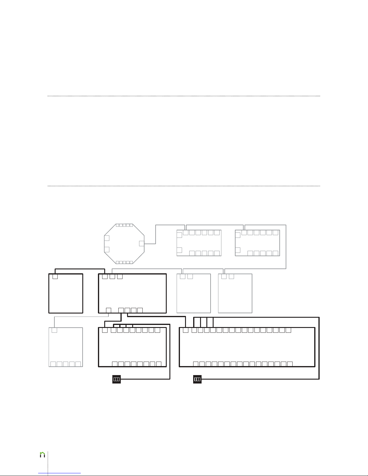
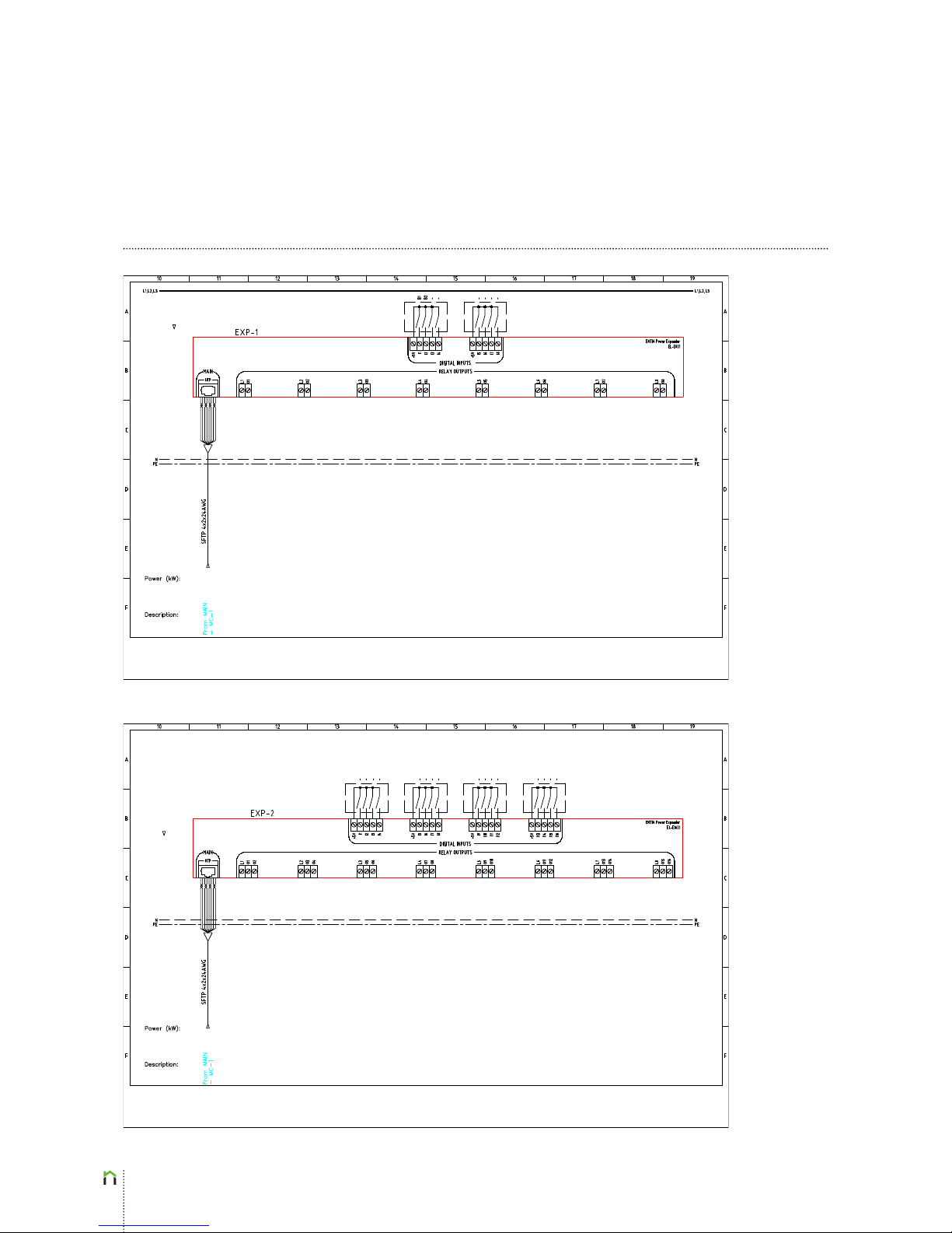
Below is the block diagram for connecting inputs (buttons, switches, digital sensors) to
the ENTIAliving system via the Power Expander (EL-E801 and EL-E1601) modules. Up to 8
digital inputs can be connected to the EL-E801 module and up to 16 digital inputs to the
EL-E1601 module.
Sens
Controller
EL-S01
Room Controller
EL-R02
DALI Converter
EL-CD01
Power Dimmer
EL-D01
MODBUS
Converter
EL-CA01
Power Supply
EL-PS01
Main Controller EL-M01
Power Expander EL-E801 Power Expander EL-E1601
Room Controller
EL-R02
2x0.75
SFTP
2 x 2 x 0,8 J(Y)-STY2 x 2 x 0,8 J(Y)-STY
Page 22
22
Buttons & Switches
Power Expander connect
Page 23
23
Buttons & Switches
BUS connect
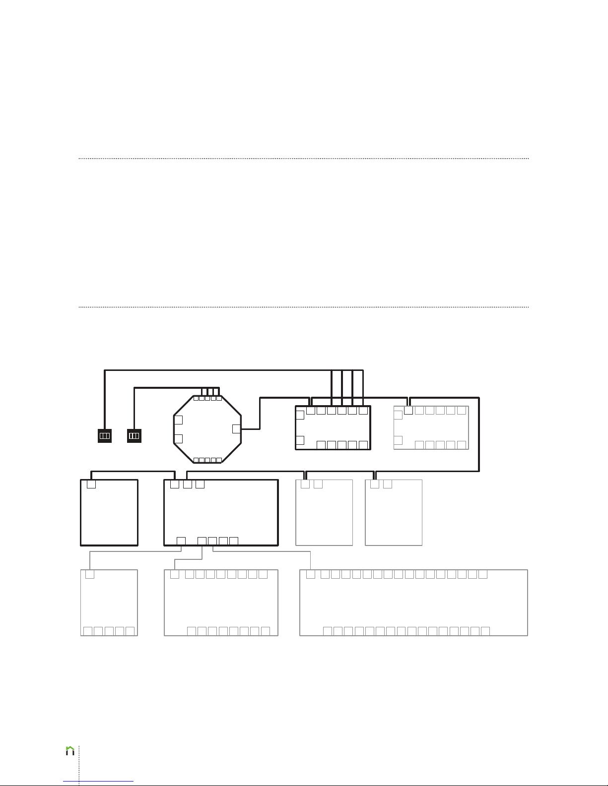
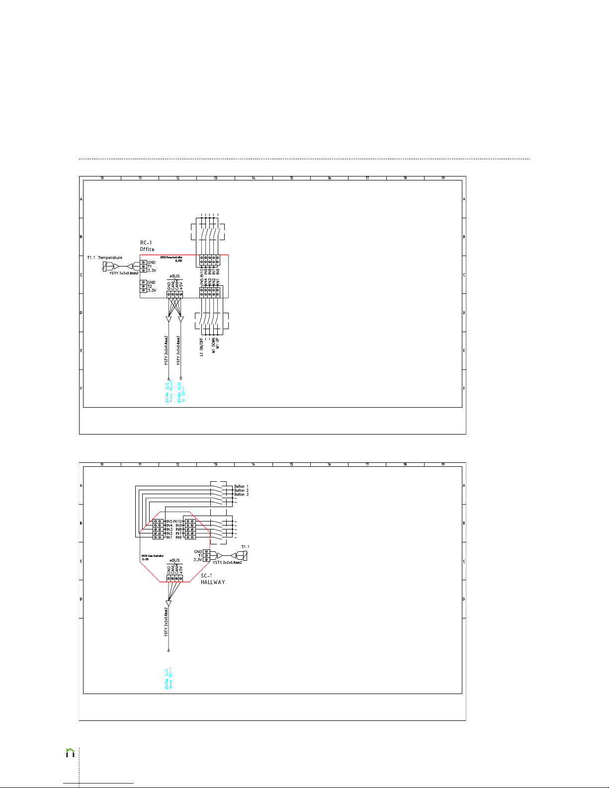
Below is the block diagram for connecting inputs (buttons, swithcehs, digital sensors) to
the ENTIAliving system via the Room Controller and/or Sens Controller (EL-R02 and EL-S01)
modules. Up to 10 digital inputs can be connected to either EL-R02 or EL-S01 module.
Sens
Controller
EL-S01
Room Controller
EL-R02
DALI Converter
EL-CD01
Power Dimmer
EL-D01
MODBUS
Converter
EL-CA01
Power Supply
EL-PS01
Main Controller EL-M01
Power Expander EL-E801 Power Expander EL-E1601
Room Controller
EL-R02
2x0.75 eBUS (CAN) J(Y)-ST-Y
SFTP
2 x 2 x 0,8 J(Y)-STY 2 x 2 x 0,8 J(Y)-STY
2 x 2 x 0,8 J(Y)-STY
2 x 2 x 0,8 J(Y)-STY2 x 2 x 0,8 J(Y)-STY
2 x 2 x 0,8 J(Y)-STY
2 x 2 x 0,8 J(Y)-STY
Page 24
24
Buttons & Switches
BUS connect
Page 25

25
ABOUT THE COMPANY
CE standards
The ENTIAliving system has passed all the necessary tests to achieve the
following standards of quality assurance:
• EN 60730-1
• EN 55015
• EN 61547
• EN 61000-3-2
• EN 61000-3-3
• EN 50491-2
• EN 50491-5-1
• EN 50491-5-2
• EN 50491-5-3
• EN 50491-3 (EN 50090:1998 + A1:2002 + A2:2007)
Our mission is to make ordinary people’s
lives easier, more effective and less costly.
We are beleivers, enthusiasts, engineers,
explorers, achievers... We are Entia.
The company Entia was founded in 2009 and
the product ENTIAliving was “born” a year later.
A cloud based smart home for new residential
buildings that increases the energy ecincy,
security and comfort of a home while enabling
world wide remote control with smartphones,
tablets or personal computers. Assembled
with the highest quality components and
manufactured in European Union, ENTIAliving
covers all the functionality of any smart
home system available on the market, adding
cloud related advantages, such as world
wide monitoring and remote control, remote
management and service etc. ENTIAliving is
moving a luxury product into the mass market
thus making smart home widely aordable.
Page 26

26
Entia d.o.o., Vodovodna 99a, 1000 Ljubljana, Slovenia, EU
 Loading...