

Enthermics ivNow Series, ivNow-1, ivNow-2, ivNow-6, ivNow-5 Operation And Care Manual
...
P RI N T ED I N U . S .A . S P E CI FI CA TI ON S A RE S UB JE C T T O C HA NG E W IT HO UT N OT I C E M A D E I N T HE U .S .A .
Operation and Care Manual
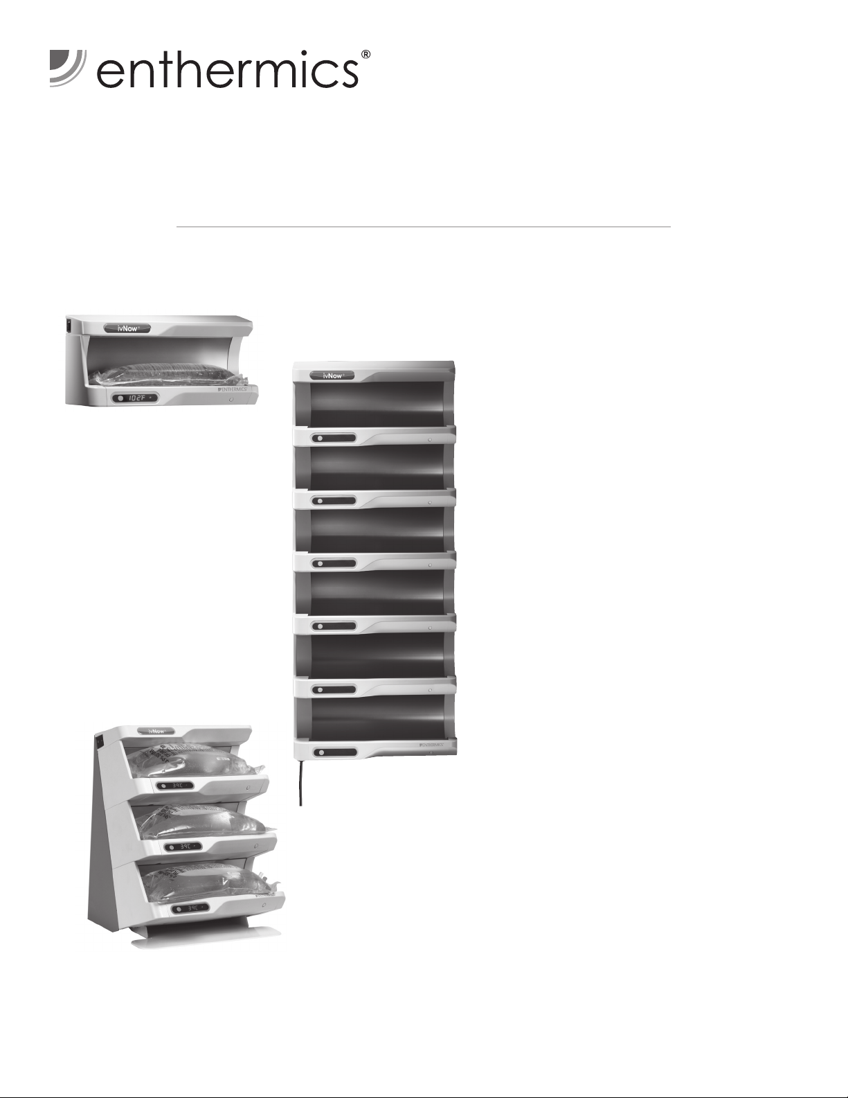
ivNow-1 countertop module
ivNow-1
ivNow-2
ivNow-3
ivNow-4
ivNow-5
ivNow-6
ivNow®
120V & 230V
ivNow-6 with Vertical Wall
Mount Bracket Kit
ENTHERMICS MEDICAL SYSTEMS
ivNow-3 with 3L Bag Tilt kit, countertop module
p ri nt e d in u . s .a .
PO Box 443, Menomonee Falls WI 53052-0443
W164 N9221 Water St, Menomonee Falls WI 53051
An ISO 13485:2003 certified company
Tel 262-251-8356 | 800-TO-B-WARM
generalinfo@enthermics.com
www.enthermics.com
MN-28929 (Rev 4) • 06/15

TABLE OF CONTENTS
Environmental Conditions . . . . . . . . . . . . . . . . . . . . . . . . . . . . 1
Delivery.....................................1
Transportation Damage and Claims................1
Unpacking...................................2
Safety Procedures and Precautions ................3
Installation
Preparation ...............................4
120V Electrical Information ...................4
230V Electrical Information ...................5
General Information.........................6
Dimension Drawings & Configurations ..........7
Options & Accessories .......................8
Operating Instructions
Control Features ...........................9
Installation...............................10
Operation Procedures.......................11
Care and Cleaning............................12
Troubleshooting Guide . . . . . . . . . . . . . . . . . . . . . . . . 13
Service Parts Lists and Drawings .................14
Wire Diagrams (Always refer to the wire diagram(s)
included with the unit for most current version.)
REPEC
Enthermics Medical Systems - The Warming Company® • www.enthermics.com
MN-28929 (REV. 4) 05/15 • IVNOW MANUAL
Authorized Representative:
MDSS GmbH
Schiffgraben 41
30175 Hannover
Germany
ENVIRONMENTAL CONDITIONS
Transport and Storage Environmental Conditions (not to exceed 15 days)
• Ambient temperature range of -40° to +70°C (-40° to +159°F).
• Relative humidity range of 10% to 95%, non-condensation.
• Atmospheric pressure range of 50KPa to 106KPa.
Operational Environmental Conditions
• Unit must acclimate to room temperature in the environment it will be placed. 24 hours is recommended.
• Recommended environmental temperature range is 15°C to 32°C (60°F to 90°F).
• Recommended relative humidity is above 20%, non-condensation.
DELIVERY
The fl uid warming module has been thoroughly tested and
inspected to insure only the highest quality unit is provided.
Upon receipt, check for any possible shipping damage and
report it at once to the delivering carrier. See Transportation
Damage and Claims section located below.
This appliance, complete with unattached items and
accessories, may have been delivered in one or more
packages. Check to ensure that all standard items and
options have been received with each model as ordered.
Save all the information and instructions packed with the
appliance. Complete and return the warranty card to the
factory as soon as possible to assure prompt service in the
event of a warranty parts and labor claim.
TRANSPORTATION DAMAGE & CLAIMS
All Enthermics Medical Systems
equipment is sold F.O.B. shipping point,
and when accepted by the carrier, such
shipments become the property of the
consignee.
Should damage occur in shipment, it is a matter between
the carrier and the consignee. In such cases, the carrier
is assumed to be responsible for the safe delivery of the
merchandise, unless negligence can be established on the
part of the shipper.
1. Make an immediate inspection while the equipment is
still in the truck or immediately after it is moved to the
receiving area. Do not wait until after the material is
moved to a storage area.
2. Do not sign a delivery receipt or a freight bill until
you have made a proper count and inspection of all
merchandise received.
3. Note all damage to packages directly on the carrier’s
delivery receipt.
This manual must be read and understood by all people
using or installing the equipment model. Contact the
service department if you have any questions concerning
installation, operation, or maintenance.
Note: Warranty registration and details are available on the
website: http://www.enthermics.com
SERIAL NUMBER IS REQUIRED FOR ALL INQUIRIES
Always include both model and serial numbers in your correspondence
regarding the unit.
Model: _____________________________________
Serial Number: _____________________________________
Purchased From: _____________________________________
Date Installed: ____________ Voltage: _______________
4. Make certain the driver signs this receipt. If he refuses
to sign, make a notation of this refusal on the receipt.
5. If the driver refuses to allow inspection, write the
following on the delivery receipt: Driver refuses to allow
inspection of containers for visible damage.
6. Telephone the carrier’s offi ce immediately upon fi nding
damage, and request an inspection. Mail a written
confi rmation of the time, date, and the person called.
7. Save any packages and packing material for further
inspection by the carrier.
8. Promptly fi le a written claim with the carrier and attach
copies of all supporting paperwork.
We will continue our policy of assisting our customers in
collecting claims which have been properly fi led and actively
pursued. We cannot, however, fi le any damage claims for
you, assume the responsibility of any claims, or accept
deductions in payment for such claims.
MN-28929 (REV. 4) 06/15 • IVNOW MANUAL • 1

UNPACKING AND SET-UP
1. Carefully remove the appliance from the carton.
NOTE: Do not discard the carton and other packaging material until you have
inspected the unit for hidden damage and tested it for proper operation.
2. Read all instructions in this manual carefully before initiating the installation of
this appliance.
DO NOT DISCARD THIS MANUAL. This manual is considered to be part of the
appliance and is to be provided to the owner or manager of the business or to the
person responsible for training operators. Additional manuals are available from
the service department.
3. Remove all protective plastic fi lm, packaging materials,
and accessories from the appliance before connecting electrical power.
MN-28929 (REV. 4) 06/15 • IVNOW MANUAL • 2
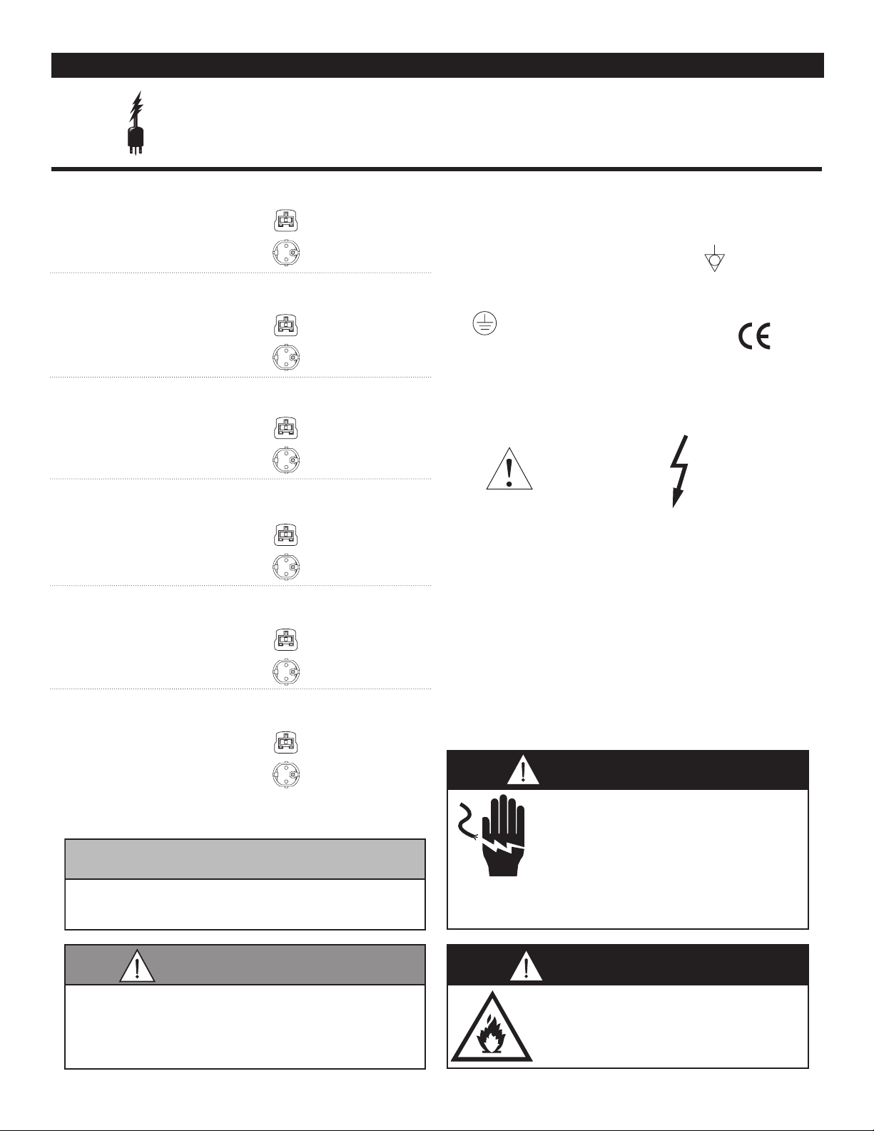
SAFETY PROCEDURES AND PRECAUTIONS
Knowledge of proper procedures is essential to the
safe operation of electrically energized equipment. In
accordance with generally accepted product safety labeling
guidelines for potential hazards, the following signal words
and symbols may be used throughout this manual.
NOTICE
solutions for irrigation and injection prior to their use. Please
purpose, limitations, and associated hazards of this device.
space and electrical source including patient support areas,
device. This manual and all supplied instructions, diagrams,
schematics, parts lists, notices, and labels must remain with
DANGER
Used to indicate the presence of a hazard that
WILL cause severe personal injury, death, or
substantial property damage if the warning
included with this symbol is ignored.
WARNING
Used to indicate the presence of a hazard that
CAN cause personal injury, possible death, or
major property damage if the warning included
with this symbol is ignored.
CAUTION
Used to indicate the presence of a hazard that
can or will cause minor or moderate personal
injury or property damage if the warning included
with this symbol is ignored.
1. Fluid warmers are ONLY intended for warming medical
refer to the labeling of the manufacturer of the products to
be warmed regarding the recommended temperature and
the duration of warming. No other use for this device is
authorized or recommended.
2. This warmer is intended for use in commercial
establishments where all operators are familiar with the
The warmer can be used wherever there is appropriate
ER, ICU, PAU, surgical suites, patient rooms, and nursing
stations. Operating instructions and warnings must be read
and understood by all operators and users.
3. Any troubleshooting guides, component views, and parts
lists included in this manual are for general reference only
and are intended for use by qualifi ed technical personnel.
4. This manual should be considered a permanent part of this
the device if the item is sold or moved to another location.
CAUTION
Used to indicate the presence of a hazard that can or
will cause minor personal injury, property damage, or a
potential unsafe practice if the warning included with this
symbol is ignored.
Used to indicate that referral to operating
instructions is a mandatory action. If not
followed the operator or patient could suffer
personal injury.
Used to indicate that referral to operating
instructions is recommended to understand
operation of equipment.
NOTICE: Used to notify personnel of installation,
operation, or maintenance information that is
important but not hazard related.
NOTE
A temporary odor may be noticeable upon initial
start-up of unit. Contact manufacturer if the odor
persists after a day or longer of continuous use.
NOTE
This unit should not be left unattended for periods of
more than 24 hours. In case of absences longer than
24 hours, disconnect the warmer from its power source.
For equipment delivered for use
in any location regulated by the
following directive:
DO NOT dispose of electrical or
electronic equipment with other
municipal waste.
MN-28929 (REV. 4) 06/15 • IVNOW MANUAL • 3
DANGER
or repairs. Do not remove, damage or
Safety Class I
Equipment
120 V.A.C. — 60 Hz, 1 ph
0.15 kW, 1.3 Amps
NEMA 5-15P
120 V.A.C. — 60 Hz, 1 ph
0.3 kW, 2.5 Amps
Mode of Operation: Continuous
NEMA 5-15P
120 V.A.C. — 60 Hz, 1 ph
0.45 kW, 3.8 Amps
Mode of Operation: Continuous
NEMA 5-15P
120 V.A.C. — 60 Hz, 1 ph
0.6 kW, 5.0 Amps
Mode of Operation: Continuous
NEMA 5-15P
120 V.A.C. — 60 Hz, 1 ph
0.75 kW, 6.3 Amps
Mode of Operation: Continuous
120 V.A.C. — 60 Hz, 1 ph
0.9 kW, 7.5 Amps
Mode of Operation: Continuous
PREPARATION
CAUTION
WARNING
Before operating the module(s), clean the exterior of the unit with a damp cloth and general hospital
cleaner (isopropyl alcohol)
ELECTRICAL INFORMATION
The power specifications are located on the unit identification nameplate. This nameplate
is permanently attached to the unit and must be located to verify power requirements.
ivNow-1 POWER REQUIREMENTS
Safety Class I Equipment
No Applied Parts
Mode of Operation: Continuous
ivNow-2 POWER REQUIREMENTS
Safety Class I Equipment
No Applied Parts
ivNow-3 POWER REQUIREMENTS
Safety Class I Equipment
No Applied Parts
ivNow-4 POWER REQUIREMENTS
Safety Class I Equipment
No Applied Parts
15A - 125V Plug
Hospital Grade
15A - 125V Plug
Hospital Grade
15A - 125V Plug
Hospital Grade
15A - 125V Plug
Hospital Grade
ivNow-5 POWER REQUIREMENTS
NEMA 5-15P
Safety Class I Equipment
No Applied Parts
15A - 125V Plug
Hospital Grade
ivNow-6 POWER REQUIREMENTS
NEMA 5-15P
Safety Class I Equipment
No Applied Parts
Grounding reliability can only be achieved when equipment is
connected to an equivalent receptacle marked “Hospital Grade.”
Medical Equipment classified by Underwriters
Laboratories with Respect to Electrical Shock,
Protective
Earth
Ground Symbol
Fire and Mechanical Hazards only, in Accordance
with UL 60601-1 and CAN/CSA C22.2 No. 601.1.
ATTENTION
Consult accompanying
documents
Hazardous Voltage Present
15A - 125V Plug
Hospital Grade
UL File No.
E201645
This unit has not been approved for
warming of blood or blood products.
Injection Fluid manufacturer suggests not to
warm injection fluids ABOVE 40°C (104°F).
If fluids are warmed ABOVE suggested
temperature, they should be discarded.
Ensure power source matches
voltage identified on appliance rating
tag. The rating tag provides essential
technical information required for any
appliance installation, maintenance
modify the rating tag.
DANGER
Do not use this warming appliance
in the presence of flammable
anesthetic mixture (with air or with
oxygen or nitrous oxide).
This could cause an explosion!
(Not category AP or APG equipment )
MN-28929 (REV. 4) 06/15 • IVNOW MANUAL • 4
Safety Class I
Equipment
230 V.A.C. — 50/60 Hz, 1 ph
0.15 kW, 0.7 Amps
230 V.A.C. — 50/60 Hz, 1 ph
0.3 kW, 1.3 Amps
230 V.A.C. — 50/60 Hz, 1 ph
0.45 kW, 2.0 Amps
230 V.A.C. — 50/60 Hz, 1 ph
0.6 kW, 2.6 Amps
230 V.A.C. — 50/60 Hz, 1 ph
0.75 kW, 3.2 Amps
230 V.A.C. — 50/60 Hz, 1 ph
0.9 kW, 3.9 Amps
*Other international plugs are available, contact factory for more information.
ELECTRICAL INFORMATION
PREPARATION
Before operating the module(s), clean the exterior of the unit with a damp cloth and general hospital
cleaner (isopropyl alcohol)
or repairs. Do not remove, damage or
DANGER
CAUTION
WARNING
The power specifications are located on the unit identification nameplate. This nameplate
is permanently attached to the unit and must be located to verify power requirements.
ivNow-1 POWER REQUIREMENTS
Type B Equipment
ivNow-2 POWER REQUIREMENTS
Type B Equipment
ivNow-3 POWER REQUIREMENTS
Type B Equipment
ivNow-4 POWER REQUIREMENTS
Type B Equipment
BS 1363 Plug*
(UK only)
CEE 7/7*
220-230V Plug
BS 1363 Plug*
(UK only)
CEE 7/7*
220-230V Plug
BS 1363 Plug*
(UK only)
CEE 7/7*
220-230V Plug
BS 1363 Plug*
(UK only)
CEE 7/7*
220-230V Plug
To prevent an electrical shock hazard between the appliance and
other appliances or metal parts in close vicinity, an equalizationbonding stud is provided. An equalization bonding lead must be
connected to this stud and the other appliances / metal parts to
provide sufficient protection against potential difference. The
terminal is marked with the following symbol.
Grounding reliability can only be achieved when equipment is
connected to an equivalent receptacle marked “Hospital Grade.”
Medical Equipment classified by Underwriters
Laboratories with Respect to Electrical Shock,
Protective
Earth
Ground Symbol
Consult accompanying
Fire and Mechanical Hazards only, in Accordance
with UL 60601-1 and CAN/CSA C22.2 No. 601.1.
ATTENTION
documents
Hazardous Voltage Present
ivNow-5 POWER REQUIREMENTS
BS 1363 Plug*
(UK only)
Type B Equipment
CEE 7/7*
220-230V Plug
ivNow-6 POWER REQUIREMENTS
BS 1363 Plug*
(UK only)
Type B Equipment
CEE 7/7*
220-230V Plug
This unit has not been approved for
warming of blood or blood products.
Injection Fluid manufacturer suggests not to
warm injection fluids ABOVE 40°C (104°F).
If fluids are warmed ABOVE suggested
temperature, they should be discarded.
MN-28929 (REV. 4) 06/15 • IVNOW MANUAL • 5
DANGER
Ensure power source matches
voltage identified on appliance rating
tag. The rating tag provides essential
technical information required for any
appliance installation, maintenance
modify the rating tag.
Do not use this warming appliance
in the presence of flammable
anesthetic mixture (with air or with
oxygen or nitrous oxide).
This could cause an explosion!
GENERAL INFORMATION
WARNING
CAUTION
The ivNow fluid warmer quickly warms and maintains the
temperature of injection/intravenous and irrigation solutions
prior to their use. The specially contoured warming module
cradles solution bags in 0.5-, 1-, 2- & 3-liter sizes. Three-liter
bag capacity available on ivNow-1, ivNow-2, & ivNow-3 with
an additional adapter. Individual ivNow units cannot be stacked
in the field. Multiple cavity units are available from the factory
in the configurations on next page. The unit is controlled by
one (1) power switch and individual electronic controls with
L.E.D. display for each cavity. The control can easily be set
to display temperatures in Celsius or Fahrenheit. A sensor in
the heating plate detects the presence of a bag and engages
the heating mechanism to quickly begin warming the fluid.
Two (2) temperature sensors work in unison to precisely and
continuously read the temperature of the bag and another
sensor monitors the plate temperature. A green ready light will
illuminate when fluid is within +0/-2°C (+0/-3ºF) of the set point
temperature. The heater will reengage as necessary to maintain
the temperature within +0/-2°C (+0/-3ºF) of the set point. The
electronic control monitors the length of time the bag has been
held at temperature, beginning when the bag reaches set point
temperature. A status button will display the time the fluid has
been held at temperature.
DANGER
At no time should the interior or
exterior be steam cleaned, hosed
down, or flooded with water or
liquid solution of any kind. Do not
use water jet to clean.
Severe damage or electrical
hazard could result. Failure to
observe this precaution will void
the warranty.
NOTE: In the event that fluid should spill inside the module,
unplug the unit to prevent an electrical shock hazard.
Wipe excess fluid from module immediately. Refer
to qualified service personnel. Qualified service
personnel should remove the module control and
remove any remaining liquid. Perform necessary
hospital electrical safety checks before returning the
unit to operation.
SAFETY FEATURES
• The control of the ivNow is designed to display an error
message (E-31) and stop heating if the temperature at the
dual sensor switch is ever above 40°C (104°F).
• The control monitors the temperature of the aluminum
plate that the heating element is attached to and it limits
the temperature to a maximum of 54°C (130°F).
• The heating pad element is in series with an automatic
cutout thermostat with a manual reset cutout thermostat
located in different locations on the heating plate. Both cut
off heat at 60°C (140°F).
This unit has not been approved for
warming of blood or blood products.
Refer to fluid manufacturer’s labeling
for recommended warming procedures.
MN-28929 (REV. 4) 06/15 • IVNOW MANUAL • 6
ivNow DIMENSIONS
Note: Individual ivNow units cannot be stacked in the fi eld.
Multiple cavity units are available from the factory in the
confi gurations below. Three-liter bag capacity available on
ivNow-1, ivNow-2, & ivNow-3 with an additional adapter.
ivNow-1
a countertop, mounted on a mobile equipment pole stand,
mounted on a wall using brackets, or mounted to a three-liter
bag tilt kit*.
ivNow-2
a countertop, mounted on a wall using mounting brackets, or
mounted to a three-liter bag tilt kit*.
ivNow-3 (three (3) bag capacity) must be mounted on a heavy
(fi ve (5) bag capacity) must be mounted on a wall using
Cord exits bottom
of wall mounted units
14.5" (368.7mm)
CORD LENGTH
44" (1118mm)
35" (890.1mm)
cord out bottom
Wall-mounted Unit
6.74" (171.2mm)
Countertop Unit
7.8" (197.7mm)**
** maintain a minimum of 4" (102mm)
clearance for bending of cord.
29.6" (752.7mm)
cord out bottom
CORD LENGTH
50" (1270mm)
14.5" (368.7mm)
24.2" (615.3mm)
cord out bottom
CORD LENGTH
55" (1397mm)
14.5" (368.7mm)
7.2" (182.1mm)
8.0" (203.1mm)
CORD LENGTH
72" (1829mm)
14.5" (368.7mm)
12.6" (318.9mm)
13.4" (340.5mm)
CORD LENGTH
66" (1676mm)
14.5" (368.7mm)
18.0" (456.9mm)
18.9" (478.8mm)
CORD LENGTH
61" (1549mm)
14.5" (368.7mm)
Note:
• Countertop unit (1 or 2 cavity), power cord exits back of unit.
• Wall mounted units (up to 6 cavities), power cord exits bottom
of unit (shown below).
• Mobile equipment pole mounted unit (up to 3 cavities), power
cord exits bottom.
• Countertop or wall mounted units (up to 3 cavities) with
three-liter bag tilt kit, power cord exits back.
†
Cord position is interchangeable, instructions available through service.
†
†
†
ivNow-1
†
ivNow-2
ivNow-3
ivNow CONFIGURATIONS
(one (1) bag capacity) can be placed directly on
(two (2) bag capacity) can be placed directly on
ivNow-6ivNow-5ivNow-4
duty mobile equipment pole stand, on a wall using mounting
brackets, or mounted to a three-liter bag tilt kit*.
ivNow-4 (four (4) bag capacity) must be mounted on a wall
using mounting brackets*.
ivNow-5
mounting brackets*.
ivNow-6 (six (6) bag capacity) must be mounted on a wall using
mounting brackets*.
MN-28929 (REV. 4) 06/15 • IVNOW MANUAL • 7
*Mounting hardware sold separately.
CO UN TE RTO P
WAL L MO UN TE D
WAL L MO UN TE D
OPA
-0 06 0- 13
ivNow OPTIONS AND ACCESSORIES
ACCESSORIES
3L Bag
Tilt Kit
GCX Light Duty Roll
Stand for Devices &
Bracket Kit
GCX Heavy Duty Roll
Stand for Devices &
Bracket Kit
Bracket Kit for
Equipment Stand
Bracket Kit for
Horizontal Wall Mount
Bracket Kit for Seismic
Horizontal Wall Mount
OPA-0698-10
Vertical Wall Channel
Mount & Bracket Kit
Bracket Kit for Vertical
Wall Channel Mount
Bracket for Mounting to
Harloff Anesthesia Cart
* See equipment diagram below
ivNow-1 ivNow-2 ivNow-3 ivNow-4, -5, -6
(cord exits back of unit)
5014126
(cord exits back of unit)
5014129
(cord exits back of unit)
5017700
mount to GCX equipment
stand - stand included
(cord exits bottom of unit)
5012246
—
mount to equipment stand or
mast - stand not included
(cord exits bottom of unit)
5012735
two (2) GCX horizontal
rails included
5012242
one (1) GCX horizontal
rail included
5016601
one (1) GCX vertical
rail included
5012241*
GCX vertical rail not included
5012288*
1015253 1015254 1015255
(cord exits back of unit)
5014127
(cord exits back of unit)
5014130
(cord exits back of unit)
5017701
— — —
mount to GCX equipment
stand - stand included
5013312
— — —
two (2) GCX horizontal
rails included
5012242
one (1) GCX horizontal
rail included
5016601
one (1) GCX vertical
rail included
5012241*
GCX vertical rail not included
5012288*
(cord exits back of unit)
5014128*
(cord exits back of unit)
5014131*
(cord exits back of unit)
5017702*
mount to GCX equipment
stand - stand included
5013312
two (2) GCX horizontal
rails included
5012242
two (2) GCX horizontal
rails included
5016602*
one (1) GCX vertical
rail included
5012241*
GCX vertical rail not included
5012288*
(cord exits bottom of unit)
two (2) GCX horizontal
two (2) GCX horizontal
one (1) GCX vertical
GCX vertical rail not included
—
—
—
—
rails included
5012242
rails included
5016602*
rail included
5012241*
5012288*
—
8
3L Bag Tilt Kit for wall
mounted units (5017702 shown)
OPA-0060-13
3L Bag Tilt Kit for countertop units
(5014128 shown)
Bracket Kit for Seismic Horizontal
Wall Mount 5016602 (ivNow-3 to -6)
OPA-0698-10
3L Bag Tilt Kit for wall
mounted units (5014131 shown)
(ivNow-6 shown above) (ivNow-1 shown above)
Vertical Wall Channel Mount Bracket Kit 5012241
MN-28929 (REV. 4) 06/15 • IVNOW MANUAL • 8
Brackets only 5012288
 Loading...