

Enthermics EC1540bl Operation And Care Manual

Co mbin a t ion
Bl a n ket/ F l uid
Wa r mi n g
Ca b i net
EC1 540 bl
120 V & 23 0 V
OPERATION AND CARE MANUAL
Corporate Headquarters:
W164 N9221 Water Street●P.O. Box 443
Menomonee Falls, Wisconsin 53052-0443
P H O N E : 2 6 2 . 2 5 1 . 8 3 5 6 8 0 0 . T O . B . W A R M U .S . A ./ C A N AD A F A X : 2 6 2 . 2 5 1 . 7 0 6 7
w w w . e n t h e r m i c s . c o m 8 0 0 .
P RI N TE D I N U. S. A.
8 6 2 . 9 2 7 6 U. S .A . /CA N A DA 8 0 0 . 3 2 9 . 8 7 4 4
●
U.S.A.
O C M / E C 1 5 4 0 b l 0 1 / 0 7
C O M B I N AT I O N B L A N K E T / F L U I D WA R M I N G C A B I N E T
T R A N S P O R T A N D S T O R A G E
Transport and Storage Environmental Conditions (not to exceed 15 days)
• Ambient temperature range of -40 to +159°F (-40° to +70°C)
• Relative humidity range of 10% to 100%, including condensation
• Atmospheric pressure range of 50KPa to 106KPa
U N P A C K I N G a n d S E T - U P
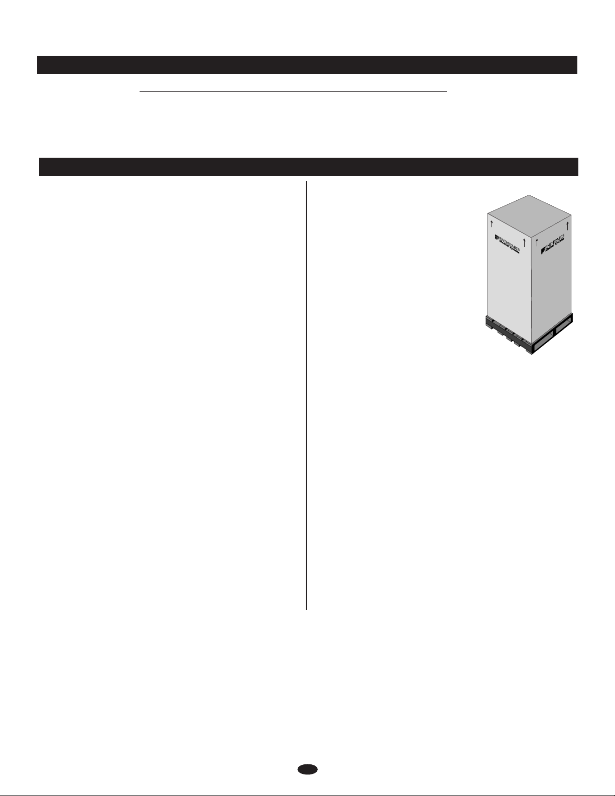
DE LI VE RY
The Enthermics Medical Systems Warming Cabinet
has been thoroughly tested and inspected to insure
only the highest quality unit is provided. Upon
receipt, check for any possible shipping damage and
report it at once to the delivering carrier. See
Transportation Damage and Claims section located
in this manual.
This appliance, complete with unattached items
and accessories, may have been delivered in one or
more packages. Check to ensure that all standard
items and options have been received with each
model as ordered.
Save all the information and instructions packed
with the appliance. Complete and return the
warranty card to the factory as soon as possible to
assure prompt service in the event of a warranty
parts and labor claim.
This manual must be read and understood by all
people using or installing the equipment model.
Contact the Enthermics service department if you
have any questions concerning installation,
operation, or maintenance.
NOTE: All claims for warranty must include the
full model number and serial number of
the unit.
UN PA C K I N G
1. Carefully remove the
appliance from the
carton or crate.
NOTE: Do not discard the
carton and other
packaging material
until you have
inspected the unit
for hidden damage
and tested it for
proper operation.
2. Read all instructions in this manual carefully
before initiating the installation of this appliance.
DO NOT DISCARD THIS MANUAL.
This manual is considered to be part of the
appliance and is to be provided to the owner
or manager of the business or to the person
responsible for training operators. Additional
manuals are available from the Enthermics
service department.
3. Remove all protective plastic film, packaging
materials, and accessories from the appliance
before connecting electrical power.
ENTHERMICS MEDICAL SYSTEMS
1
O C M / E C 1 5 4 0 b l 0 1 / 0 7
SAFETY PROCEDURES A N D P R E C A U T I O N S
Enthermics warmers should not be left unattended for
periods of more than 24 hours. In case of absences
longer than 24 hours, disconnect the warmer from its
power source.
Knowledge of proper procedures is essential to the
safe operation of electrically and/or gas energized
quipment. In accordance with generally accepted
e
roduct safety labeling guidelines for potential
p
azards, the following signal words and symbols
h
ay be used throughout this manual.
m
Used to indicate the
presence of a hazard that
will cause severe personal
injury, death, or substantial
property damage if the
warning included with this
symbol is ignored.
Used to indicate the
presence of a hazard that
ca n cause personal injury,
possible death, or major
property damage if the
warning included with this
symbol is ignored.
Used to indicate the
presence of a hazard that
can or will cause minor or
moderate personal injury
or property damage if the
warning included with this
symbol is ignored.
Used to indicate the
presence of a hazard that
can or will cause minor
personal injury, property
damage, or a potential
unsafe practice if the
warning included with this
symbol is ignored.
1. Enthermics blanket warmers are intended for
warming cotton blankets ONLY. No other use
or this device is authorized or recommended.
f
nthermics fluid warmers are ONLY intended
E
or warming medical solutions for irrigation and
f
injection. The IRRIGATION MODE should be
selected for warming irrigation fluids, and the
INJECTION MODE should be selected for
warming injection fluids. Please refer to the
labeling of the manufacturer of the products to be
warmed regarding the recommended temperature
and the duration of warming. No other use for
this device is authorized or recommended.
2. This device is intende d fo r use in com mercial
es tablishments where all opera tors are familiar
wi th the purpose , li mitations, and ass oci ated
ha zards o f th is devi ce. Operating instruc tions
an d wa rnings must be read and understood by
al l op erators and users.
3. Any troubleshooting guides, component views, and
parts lists included in this manual are for general
reference only and are intended for use by qualified
technical personnel.
4. This manual should be considered a permanent
part of this device. This manual and all supplied
instructions, diagrams, schematics, parts lists,
notices, and labels must remain with the device
if the item is sold or moved to another location.
NOT E:
Used to notify personnel of
installation, operation, or
maintenance information that is
important but not hazard related.
ENTHERMICS MEDICAL SYSTEMS
2
O C M / E C 1 5 4 0 b l 0 1 / 0 7
P R E P A R A T I O N
DO NOT use this warming cabinet in the
presence of a flammable anethestic mixture
(with air or with oxygen or nitrous oxide).
THIS COULD RISK AN EXPLOSION!
INJECTION FLUIDS SHOULD NOT
BE WARMED OVER 110°F (43° C)
THIS UNIT HAS NOT BEEN
APPROVED FOR WARMING OF
BLOOD OR BLOOD PRODUCTS.
Before operating the cabinet, clean both the interior and exterior of the unit with a damp cloth and mild
soap solution. Wipe with an appropriate disinfectant. Clean and install the cabinet basket support
assembly and the blanket support assembly.
E L E C T R I C A L I N F O R M A T I O N
The power specifications are located on the unit identification nameplate. This nameplate is
permanently attached to the unit and must be located to verify power requirements.
POWER REQUIREMENTS - EC1540bl (120V)
EM A 5-2 0P
120 V.A.C. — 50/60 Hz, 1 ph
1920 Watts, 16.0. Amps
Safety Class I Equipment
Grounding reliability can only be achieved when equipment is
connected to an equivalent receptacle marked "Hospital Grade."
Medical Equipment classified by Underwriters
Laboratories with Respect to Electrical Shock,
Protective Earth
Ground Symbol
Hazardous
Voltage Present
Fire and Mechanical Hazards only, in Accordance
ith UL 60601-1 and CAN/CSA C22.2 No. 601.1.
w
N
20A - 125V Plug
Hospital Grade
UL File No.
E201645
POWER REQUIREMENTS - EC1540bl (230V)
230 V.A.C. — 50/60 Hz, 1 ph
1700 Watts, 7.5 Amps
Type B Equipment
To prevent an electrical shock hazard between the appliance and other
appliances or metal parts in close vicinity, an equalization-bonding stud
is provided. An equalization bonding lead must be connected
to this stud and the other appliances / metal parts to provide
sufficient protection against potential difference. The terminal
is marked with the following symbol.
S 1363 Plug
B
(UK only)
C
EE 7/7
220-230V Plug
IMPORTANT
Do not lo ad th e meta l bask e t bey o nd th e
recommended maximum capacity of 14 liters.
Ove r loading may caus e low e r o r u n even
temperatures of product and damage to basket and
basket rail supports. Baskets that are overloaded
may slip off rail supports, resulting in possible
damage to product and equipment, as well as
causing possible injury.
ENTHERMICS MEDICAL SYSTEMS
3
O C M / E C 1 5 4 0 b l 0 1 / 0 7
G E N E R A L I N F O R M A T I O N
AT NO TIME SHOULD THE INTERIOR OR
EXTERIOR BE STEAM CLEANED, HOSED
DOWN, OR FLOODED WITH WATER OR
LIQUID SOLUTION OF ANY KIND. DO NOT
USE WATER JET TO CLEAN.
SEVERE DAMAGE OR ELECTRICAL HAZARD
COULD RESULT.
WARRANTY BECOMES VOID IF APPLIANCE IS FLOODED.
THIS UNIT HAS NOT BEEN
APPROVED FOR WARMING OF
BLOOD OR BLOOD PRODUCTS.
This warming cabinet is designed to safely store warm
ither irrigation fluids or injection fluids and blankets.
e
he dual-chambered warming cabinet is constructed
T
ith a 20 gauge stainless steel exterior casing and door with
w
andles and hinges designed to withstand heavy usage. A
h
door with window allows observation of inventory with the
door closed. The cabinet is warmed using the patented Halo
®
low-heat-density electrothermal cable array. The
Heat
electrothermal cable is positioned in the floor and two sides
of the warming cabinet, providing even heating of the
interior chamber. Each chamber temperature is regulated by
a separate electronic control. A fan located inside the
chamber mixes the air to prevent temperature stratification
and to ensure an accurate chamber temperature within
±2°F (±1.1°C) of the set point for temperatures up to
110°F (43°C) and within ±3°F (±1.6°C) of the set point for
temperatures above 110° to 150°F (43°C to 66°C). Each
chamber has an individual electronic control consisting
of a 4 digit L.E.D. display, ON/OFF key, INCREASE and
DECREASE keys, integrated LOCK feature and a series of
prompt sequence indicators.
The (upper) blanket warming chamber has an adjustable
temperature range of 90° to 200°F (32° to 94°C). This
chamber also has a TIMER mode that allows the user to
program the control to automatically turn on and turn off
once during a 24-hour period at a selected time. This
enables the blanket warming chamber (only) to be shut off
automatically at night to save energy, but to turn on again in
the early morning to ensure warm blankets are available.
The (lower) fluid warming chamber can be programmed
o warm either irrigation fluids (IRR) or injection fluids
t
INJ), with separate temperature ranges provided depending
(
n the choice selected. IRR temperature may be adjusted
o
rom 90° to 150°F (32° to 66°C), and the INJ temperature
f
can be adjusted from 90° to 110°F (32° to 43°C). An alarm
will sound if temperatures exceed 10°F (6°C) over the set-
point temperature, and a TEMP indicator will blink
indicating an over-temperature condition.
A warming shut-off system, separate from the electronic
controls, prevents overheating. The electronic controls can
easily be set to operate in Fahrenheit or Celsius. After a
power failure, the cabinet will remember its programming
and begin to operate as before. The ON/OFF indicator will
blink to indicate a failure occurred; pressing the ON/OFF
key once will eliminate this blinking.
The blanket warming chamber contains an epoxy-coated
blanket support assembly and one (1) shelf. The fluid
warming chamber is equipped with three (3) white, epoxy-
coated wire baskets to accommodate fluids packaged in bags
or bottles, mounted on basket rail supports. Each basket has
a 14 liter maximum capacity. The cabinet is furnished
with a full perimeter rubber bumper assembly for exterior
protection, and one (1) set of 5" (127mm) heavy-duty
casters, two with locking brake.
ENTHERMICS MEDICAL SYSTEMS
4
O C M / E C 1 5 4 0 b l 0 1 / 0 7

D I M E N S I O N S
33.100" (840.89mm)
53.000" (1345.58mm)
34.900" (886.40mm)
28.800" (730.81mm)
25.100"
(636.40mm)
30.000" (463.04mm)
11.000"
(280.03mm)
2.200" (56.34mm)
18.900"
(480.29mm)
Cavity
22.125"
(561.98mm)
67.000" (1702.61mm)
5.500" (139.22mm)
25.200" (639.22mm)
26.900" (683.49mm)
Cavity
26.900" (683.49mm)
Cavity
72.500" (1841.83mm)
ON
OFF
OVER
TEMP
IRR INJ
LOCKOVERTEMP
ERROR
ON
OFF
L
OCK
T
IME START
STOP
TIMER
11.000"
(280.03mm)
ENTHERMICS MEDICAL SYSTEMS
5
O C M / E C 1 5 4 0 b l 0 1 / 0 7
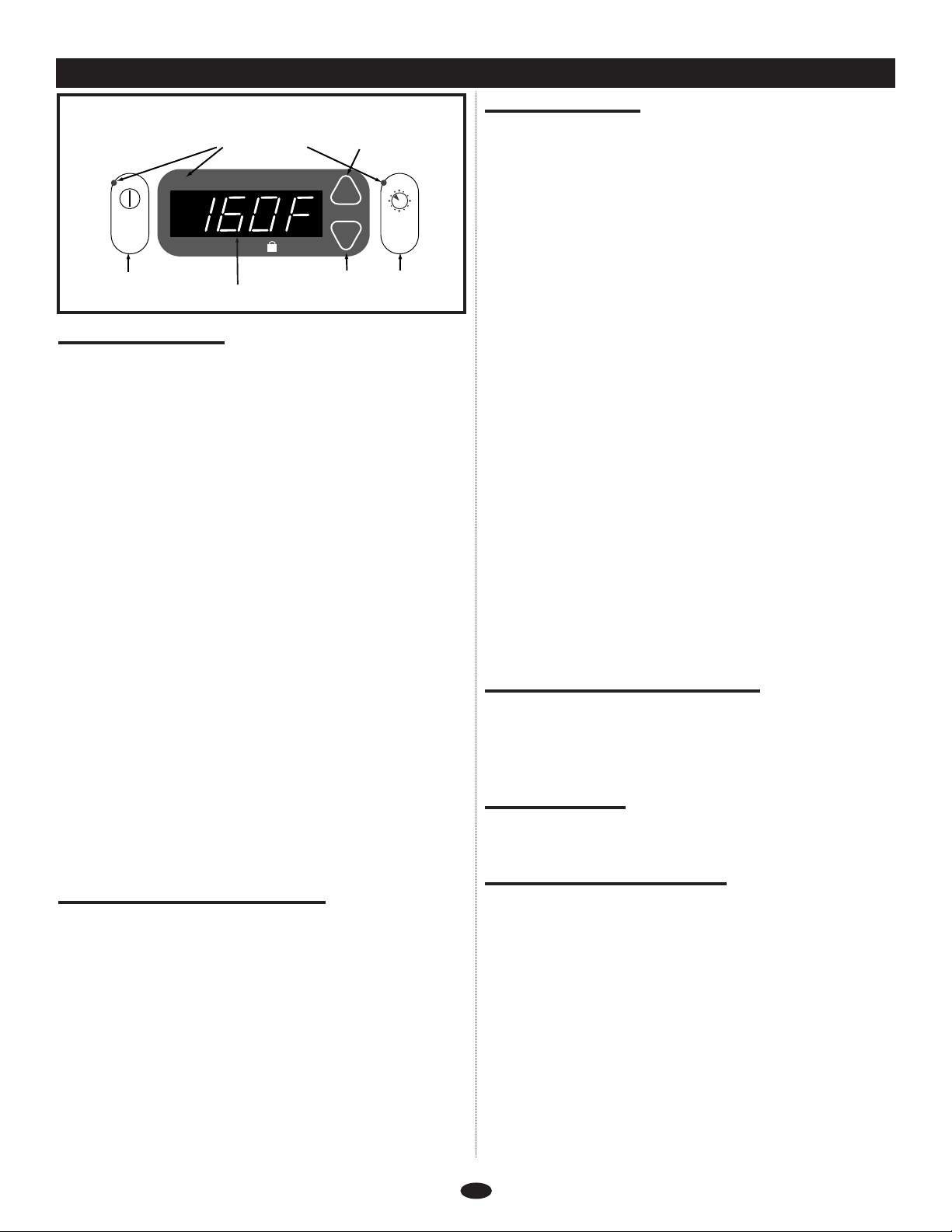
B L A N K E T C O N T R O L F E A T U R E S ( U P P E R C H A M B E R )
O
N
OFF
LOCK
T
IME START
S
TOP
L.E.D.
DISPLAY
S
TATUS INDICATOR L.E.D. UP ARROW
D
OWN ARROW AUTO TIMER
K
EY
O
N / OFF
K
EY
L
.E.D. = LIGHT EMITTING DIODE
TIMER
THERMOSTAT CONTROL AND L.E.D. DISPLAY
CONTROL PANEL KEYS
ON/OFF KEY
Press and release the on/off key to activate the blanket
compartment control (upper chamber). The unit will
beep and the status indicator, located at the top left of
the ON/OFF key, will illuminate when the warmer is
on. To turn the control off, press and hold the ON/OFF
key for 3 seconds. The unit will beep and the status
indicator will extinguish.
UP ARROW / DOWN ARROW KEYS
These keys are used to increase or decrease the temperature
set-point as desired. They are also used to set the current
time of day and to select a desired start time and stop time
when adjusting the Auto Timer.
TIMER KEY
This 24-hour timer feature is a three-step process that
provides automatic shut-down for energy savings in
off-hours and preset start-up so blankets are warm
before needed. The L.E.D. display shows a 24-hour
clock; i.e. 1:00 p.m. will display as 13:00.
L.E.D. DIGITAL DISPLAY
The control has a four-digit L.E.D. display. When
the control is activated, the display will show current
temperature set-point. When programming the Auto
Timer, the display will show hour and minutes.
L.E.D. DISPLAY STATUS INDICATORS
TIME
Illuminates while current time of day is displayed when
programming the TIMER mode.
START
Illuminates while the start time is displayed when
programming the TIMER mode.
STOP
Illuminates while the stop time is displayed when
programming the TIMER mode.
LOCK
Illuminates when the lock feature is engaged.
ENTHERMICS MEDICAL SYSTEMS
OWER FAIL DETECT
P
If the power were to fail for any reason while heating,
the warmer will retain, in memory, its current operating
state. When the power is restored, the control will resume
operating, but several things will alert the operator that
uch an event has occurred:
s
A. The ON/OFF status indicator will be flashing.
B. Display will indicate '128' (or another number) alternating
with the setting. Please see important note below if a
number other than '128' is displayed.
C. Control will "beep" every third flash of the
number displayed.
Press the ON/OFF key once to acknowledge that the power
has been restored. The ON/OFF status indicator will stop
flashing and the "beep" will be silenced. The display will
indicate the approximate time period of the outage, then
return to the normal display and previously set mode.
Note: The display of '128' is a normal Power-On Reset for
the control. Any other number displayed may indicate
a problem. Make note of the number, and if the unit
fails to operate properly, provide that number to
service to assist them in troubleshooting the problem.
Note: Programming is done with power circuit breaker switch
at the back of the appliance "ON", but ON/OFF Key on
the control panel "OFF".
FAHRENHEIT OR CELSIUS SELECTION
While the controller is in the off mode, press and hold the
UP ARROW key until you hear a beep (approximately
5 seconds). The warmer will switch between Fahrenheit
or Celsius.
BEEPER ON OR OFF
While the controller is in the off mode, press and hold the
DOWN ARROW key. "OFF" will not beep.
SETTING CURRENT TIME OF DAY
Setting the current time of day must be done first to ensure
proper operation of timer function. To set the current time
of day, the control must be in the off mode, with the
ON/OFF status indicator extinguished. Press and hold the
TIMER key to illuminate various indicators. Release. Repeat
the process until the Time status indicator is illuminated.
The display will show the currently set time of day.
Continue to hold the TIMER key, and use the UP or
DOWN arrow keys to synchronize with the current time of
day. Note: The L.E.D. display shows a 24-hour clock; i.e.
1:00 p.m. will display as 13:00.
6
O C M / E C 1 5 4 0 b l 0 1 / 0 7
 Loading...