

Enthermics DC250, Designer Series, DC150, DC350, DC750 Operation And Care Manual
...
Enthermics Medical Systems
Operation and Care Manual
Designer Series Blanket Warmer
DC150
DC350
DC250
DC150
(shown with optional timer)
DC750
(shown with optional timer)
DC400
(shown with optional timer)
W164 N9221 Water St, Menomonee Falls WI 53051
Printed in the U.S.A. Specifications are Subject to Change Without Notice
DC250
DC350
DC400
DC750
An ISO 13485:2003 certified company
PO Box 443, Menomonee Falls WI 53052-0443
Tel 262-251-8356 | 800-TO-B-WARM
generalinfo@enthermics.com
www.enthermics.com
Made in the U.S.A.
MN-37072 • Rev 2 • 05/16
Table of Contents
Delivery . . . . . . . . . . . . . . . . . . . . . . . . . . . . . . . . 1
Transportation Damage and Claims . . . . . . . . . . . . . . . . 1
Unpacking . . . . . . . . . . . . . . . . . . . . . . . . . . . . . . . 2
Safety Procedures . . . . . . . . . . . . . . . . . . . . . . . . . . 3
Installation . . . . . . . . . . . . . . . . . . . . . . . . . . . . . . 4
Dimensions . . . . . . . . . . . . . . . . . . . . . . . . . . . . . . 5
Electrical Information . . . . . . . . . . . . . . . . . . . . . . . . 6
Operation Instructions . . . . . . . . . . . . . . . . . . . . . . . 9
Cleaning and Preventative Maintenance . . . . . . . . . . . . 14
Dimension Drawings . . . . . . . . . . . . . . . . . . . . . . . 16
Troubleshooting . . . . . . . . . . . . . . . . . . . . . . . . . . 30
Service . . . . . . . . . . . . . . . . . . . . . . . . . . . . . . . . 32
Wiring Diagrams Refer to the wire diagram located under the lid of the appliance.
REPEC
MN-37072 • Rev 2 • 05/16 • Designer Series Blanket Warmer
Authorized Representative:
MDSS GmbH
Schi graben 41
30175 Hannover
Germany
Delivery
Environmental Conditions
Transport and storage environmental conditions (not to exceed 15 days)
• Ambient temperature range of -40°C to +70°C (-40°F to +159°F)
• Relative humidity range of 10% to 95%, non-condensing
• Atmospheric pressure range of 50KPa to 106KPa
Operational environmental conditions
• Appliance must acclimate to room temperature in the environment it will be placed. 24 hours is recommended.
• Recommended environmental temperature range is 15°C to 32°C (60°F to 90°F).
• Recommended relative humidity is above 20%, non-condensing.
Receipt of Appliance
The appliance has been thoroughly tested and
inspected to ensure only the highest quality appliance
is provided. Upon receipt, check for any possible
shipping damage and report it at once to the delivering
carrier. See Transportation Damage and Claims section
locatedbelow.
This appliance, complete with unattached items and
accessories, may be delivered in one or more packages.
Confi rm that all standard items and options have been
received with each appliance as ordered. Save all the
information packed with the appliance.
This manual must be read and understood by all
people using or installing the appliance. Contact the
Enthermics service department if there are any questions
concerning installation, operation, or maintenance.
Transportation Damage and Claims
All Enthermics Medical Systems appliances
are sold F.O.B. shipping point, and when
accepted by the carrier, such shipments
become the property of the consignee.
Should damage occur in shipment, do not put the
appliance into service until the damage has been
inspected by an authorized service provider.
Should damage occur in shipment, it is a matter between
the carrier and the consignee. In such cases, the carrier
is assumed to be responsible for the safe delivery of the
merchandise, unless negligence can be established on the
part of the shipper.
1. Conduct an immediate inspection while the appliance
is still in the truck or immediately a er it is moved
to the receiving area. Do not wait until a er the
appliance is moved to a storage area.
2. Do not sign a delivery receipt or a freight bill until
a proper count has been made and inspection of all
appliances are received.
3. Note all damage to packages directly on the carrier’s
delivery receipt.
Register the unit online to assure prompt service in the
event of a warranty parts and labor claim.
http://www.enthermics.com/warranty-registration
Serial number is required for all inquiries.
Always include both model and serial number(s) in any
correspondence regarding the appliance.
Model: ______________________________________________
Serial Number: ______________________________________________
Purchased From: ______________________________________________
Date Installed: ____________________ Voltage: _____________
4. Have the driver sign the delivery receipt. If he refuses
to sign, make a notation of this refusal on the receipt.
5. If the driver refuses to allow inspection, write the
following on the delivery receipt: Driver refuses to
allow inspection of containers for visible damage.
6. Contact the carrier’s offi ce immediately upon fi nding
damage, and request an inspection. Mail
a written confi rmation of the time, date, and the
person called.
7. Save any packages and packing material for further
inspection by the carrier.
8. Promptly fi le a written claim with the carrier and
attach copies of all supporting paperwork.
Enthermics will continue our policy of assisting our
customers in collecting claims which have been properly
fi led and actively pursued. Enthermics cannot, however,
fi le any damage claims, assume the responsibility of any
claims, or accept deductions in payment for such claims.
MN-37072 • Rev 2 • 05/16 • Designer Series Blanket Warmer
1
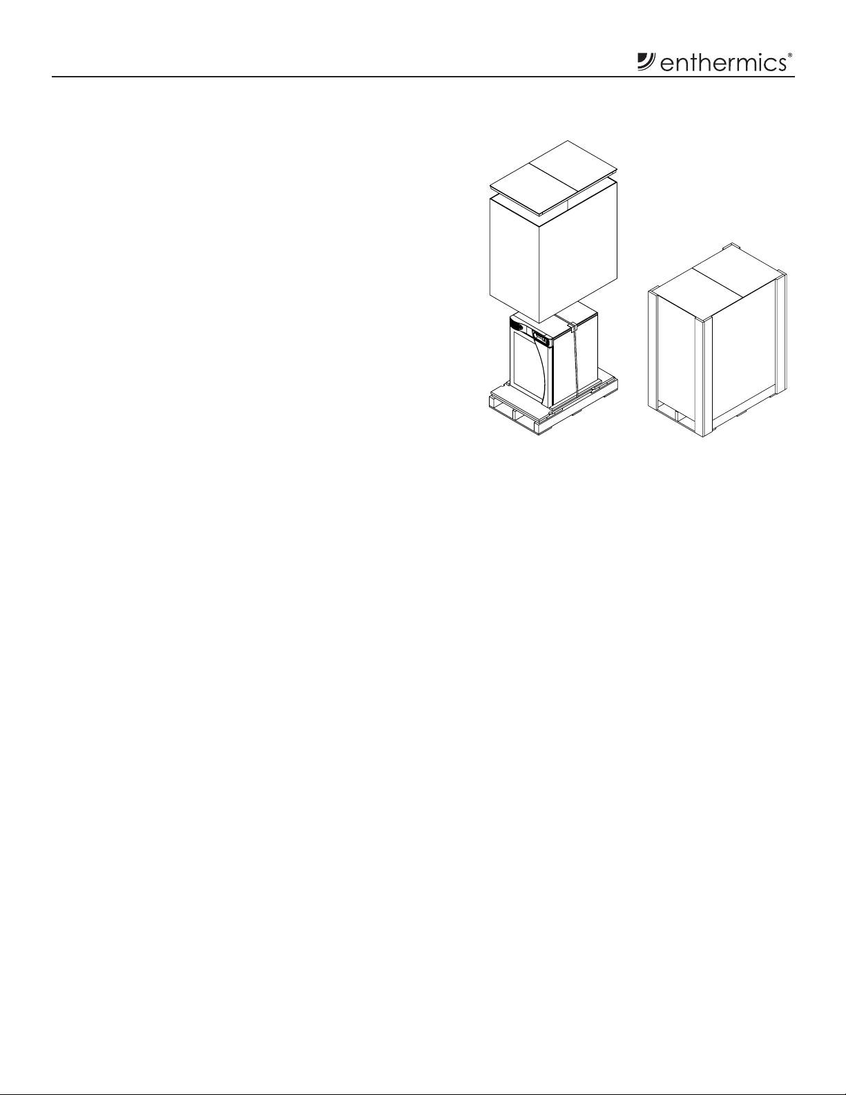
Unpacking
1. Carefully remove the appliance from the carton or crate.
NOTE: Do not discard the carton and other packaging material
until the appliance has been inspected for hidden
damage and tested for proper operation.
2. Read all instructions in this manual carefully before initiating
the installation of this appliance, using the appliance or
performing routine maintenance. Following procedures
other than those indicated in this guide to use and clean
the appliance is considered inappropriate and may cause
damage, injury or fatal accidents, in addition to invalidating
the guarantee and relieving the manufacturer of all liability.
3. Do not discard this manual. This manual is considered to
be part of the appliance and is to be provided to the owner
or manager of the business or to the person responsible for
training operators. Additional manuals are available from
the service department.
4. Remove all protective plastic fi lm, packaging materials,
and accessories from the appliance before connecting
electrical power. Store any accessories in a convenient
place for future use.
2
MN-37072 • Rev 2 • 05/16 • Designer Series Blanket Warmer
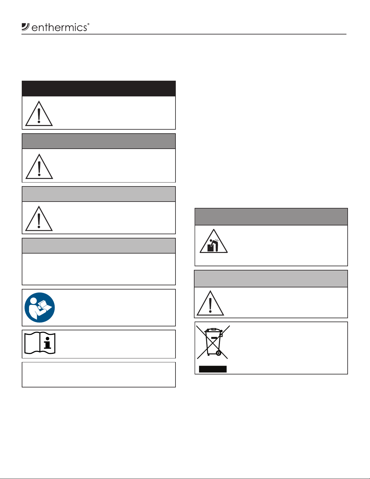
Safety Procedures
Knowledge of proper procedures is essential to the
• This blanket warmer is intended for warming dry,
CAUTION
WARNING
NOTICE: A temporary odor may be noticeable upon initial
continuous use.
safe operation of electrically energized appliances. The
following hazard signal words and symbols may be used
throughout this manual.
DANGER
Used to indicate the presence of a hazard
that will cause severe personal injury, death,
or substantial property damage if the warning
included with this symbol is ignored.
WARNING
Used to indicate the presence of a hazard
that CAN cause personal injury, possible
death, or major property damage if the
warning included with this symbol is ignored.
CAUTION
Used to indicate the presence of a hazard
that can or will cause minor or moderate
personal injury or property damage if the
warning included with this symbol is ignored.
CAUTION
Used to indicate the presence of a hazard that can or
will cause minor personal injury, property damage, or a
potential unsafe practice if the warning included with this
symbol is ignored.
cotton blankets only. No other use for this appliance is
authorized or recommended.
• This warmer is intended for use in commercial
establishments where all operators are familiar with
the purpose, limitations, and associated hazards of
this device. The warmer can be used wherever there
is appropriate space and electrical source including
patient support areas, ER, ICU, PACU, surgical suites,
patient rooms, and nursing stations.
• Operating instructions and warnings must be read and
understood by all operators and users.
• Any troubleshooting guides, component views, and
parts lists included in this manual are for general
reference only and are intended for use by qualifi ed
technical personnel.
• This manual should be considered a permanent
part of the appliance. This manual and all supplied
instructions, diagrams, schematics, parts lists, notices,
and labels must remain with the appliance if the item is
sold or moved to another location.
Appliance and accessories may be
heavy. To prevent serious injury, always
use a su icient number of trained and
experienced workers when moving or
leveling appliance and handling accessories.
Used to indicate that referral to operating
instructions is a mandatory action. If not
followed, the operator or patient could su er
personal injury.
Used to indicate that referral to operating
instructions is recommended to understand
operation of the appliance.
NOTICE: Used to notify personnel of installation,
operation, or maintenance information that is
important but not hazard related.
start-up of the appliance. Contact manufacturer
if the odor persists a er a day or more of
MN-37072 • Rev 2 • 05/16 • Designer Series Blanket Warmer
The door may swing during transport. Only
transport the appliance when the door is
closed and secure.
NOTICE: For appliances delivered for use
in any location regulated by the
following directive (
Do not dispose of electrical or
electronic appliances with other
municipal waste.
NOTICE: Due to the energy e icient design of the
appliance and tight seal around the door, water
vapor from moist or damp blankets placed in the
appliance may cause condensation to collect on
interior surfaces. To avoid this accumulation, use
dry blankets or towels.
2012/19/EU -WEEE):
3

Installation
DANGER
use water jet toclean. Failure
DANGER
Not category AP or APG equipment
Speci cations:
Electronic Control:
Additional features:
Clearance requirements:
Preparation
General Information
• Single-chamber warming appliance
• White epoxy-coated steel exterior
casing and interior insert
• Single pane, energy-effi cient,
e-coated glass window in door
allows for inventory observation
• Easy push-button door for handsfree operation
• Door is fully gasketed and hinged on
the right side of the unit
• WarmSafe™ incorporates a multiple
zone warming technology (Patent
No: US 8,217,316; US 8,581,152) that
heats where and when it is needed.
All chamber surface temperatures
are monitored, providing an
effi cient balance of heat, low-energy
consumption and minimal heat loss.
• DC350 & DC750 include a heated
center shelf to further optimize heat
distribution throughout the cavity
• Four (4) non-skid rubber feet
are standard
To prevent serious personal injury, death, or
property damage:
Do not steam clean, hose down or flood the
interior or exterior with water or liquid solution
of any kind. Do not
to observe this precaution will void the warranty.
Before operating the appliance, clean both the interior and exterior with a damp cloth and mild soap
solution. Wipe with an appropriate disinfectant. Wipe dry with a clean cloth or air dry.
• Adjustable temperature range of
32°C - 71°C (90°F - 160°F)
• Operates in celsius or fahrenheit
• Four digit LED display
• On/Off button
• Up and down adjustment buttons
• Actual temperature button
• Interior light button
• Built-in speaker for audible feedback
• Integrated control lockout feature
1" (25mm) from top and sides
3/4" (19mm) from bottom
3" (76mm) from rear
To prevent serious injury, death, or
property damage:
Do not use this warming appliance in
the presence of flammable anesthetic
mixtures (with air or with oxygen or
nitrous oxide).
• LED interior lighting casts a
comforting blue glow with two (2)
different intensity settings and
off mode.
• Safety: In the event of a power
failure the appliance will retain
its programming and operates as
previously set when power
is restored.
• Safety: A warming shut-off system,
separate from the electronic
control, prevents overheating.
• Convenience: Access point
and removable cover on the
back panel allows the addition
of data logging or temperature
management hardware.
• Convenience: Stackable
confi gurations are available
for additional capacity or to
pair with fl uid warmers.
4
MN-37072 • Rev 2 • 05/16 • Designer Series Blanket Warmer

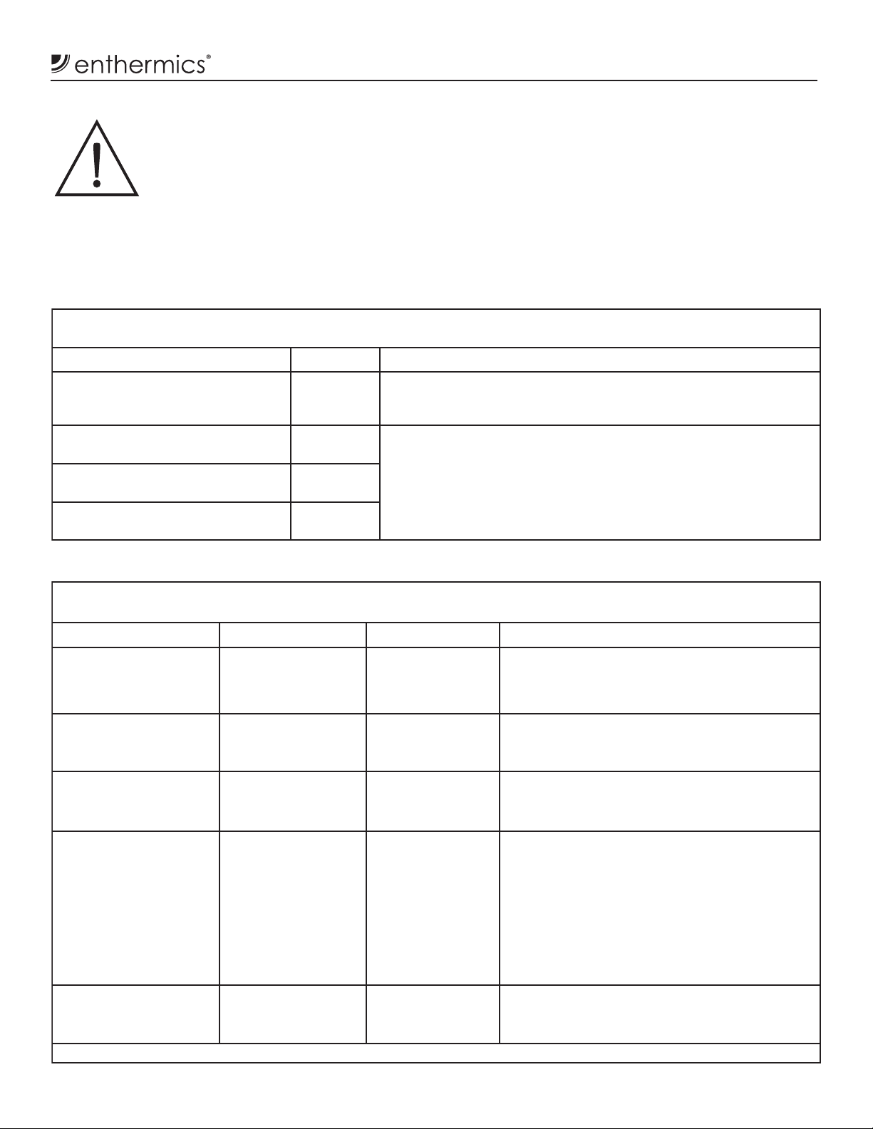
Dimensions (H x W x D)
Capacity
Weight**
Dimensions (H x W x D)
Capacity
Weight**
Dimensions (H x W x D)
Capacity
Weight**
DC150
**Domestic ground shipping information. Contact factory for export weight and dimensions.
Dimensions (H x W x D)
Capacity
Weight**
Dimensions (H x W x D)
Capacity
Weight**
With feet (standard): 17.0" x 18.5" x 22.7" (431mm x 470mm x 577mm)
With casters
(optional): 20.5" x 18.5" x 22.7" (520mm x 470mm x 577mm)
1.5 3
(est.)
Net: 56 lbs (25 kg) Ship: 98 lbs (44 kg)
DC250
With feet (standard): 21.9" x 18.5" x 25.7" (557mm x 470mm x 653mm)
With plate and
(optional):
casters
With bumper and
casters
(optional):
(est.)
26.3" x 18.5" x 25.7" (667mm x 470mm x 653mm)
26.3" x 21.3" x 25.9" (667mm x 540mm x 657mm)
3
2.5
Net: 67 lbs (30 kg) Ship: 118 lbs (54 kg)
DC350
Dimensions
With feet (standard): 27.9" x 18.5" x 25.7" (709mm x 470mm x 653mm)
With plate and
(optional):
casters
With bumper and
casters
(optional):
DC400
With feet (standard): 21.9" x 24.0" x 28.0" (557mm x 610mm x 712mm)
With plate and
(optional):
casters
With bumper and
casters
(optional):
DC750
With feet (standard): 35.4" x 24.0" x 28.0" (900mm x 610mm x 712mm)
With bumper and
(optional):
casters
With casters
32.2" x 18.5" x 25.7" (819mm x 470mm x 653mm)
32.2" x 21.3" x 25.9" (819mm x 540mm x 657mm)
3.5 3
(est.)
(est.)
(optional): 40.7" x 24.0" x 28.0" (1033mm x 610mm x 712mm)
(est.)
Net: 91 lbs (41 kg) Ship: 146 lbs (66 kg)
26.1" x 24.0" x 28.0" (664mm x 610mm x 712mm)
26.2" x 26.8" x 28.9" (665mm x 679mm x 734mm)
4.0 3
Net: 85-1/2 lbs (439 kg) Ship: 160 lbs (73 kg)
39.3" x 26.8" x 28.0" (997mm x 679mm x 712mm)
7.5 3
Net: 134 lbs (61 kg) Ship: 196 lbs (89 kg)
MN-37072 • Rev 2 • 05/16 • Designer Series Blanket Warmer
5
Electrical Information
CAUTION
DANGER
Not category AP or APG equipment
For CE approved appliances: To prevent an
following symbol.
26.3" x 18.5" x 25.7" (667mm x 470mm x 653mm)
26.3" x 21.3" x 25.9" (667mm x 540mm x 657mm)
2.5 3
Net: 67 lbs (30 kg) Ship: 118 lbs (54 kg)
120 V.A.C. — 60 Hz, 1 ph
0.6 kW, 5.0 Amps
NEMA 5-15P
220 V.A.C. — 50Hz, 1 ph
0.6 kW, 2.7 Amps
Type B Equipment
CEE 7/7*
IPX-0
230 V.A.C. — 50 Hz, 1 ph
0.6 kW, 2.6 Amps
IPX-0
39.3" x 26.8" x 28.0" (997mm x 679mm x 712mm)
7.5 3
Net: 134 lbs (61 kg) Ship: 196 lbs (89 kg)
120 V.A.C. — 60 Hz, 1 ph
0.8 kW, 6.7 Amps
NEMA 5-15P
220 V.A.C. — 50Hz, 1 ph
0.8 kW, 3.6 Amps
Type B Equipment
CEE 7/7*
IPX-0
230 V.A.C. — 50 Hz, 1 ph
0.8 kW, 3.5 Amps
IPX-0
1.5 3
Net: 56 lbs (25 kg) Ship: 98 lbs (44 kg)
120 V.A.C. — 60 Hz, 1 ph
0.6 kW, 5.0 Amps
NEMA 5-15P
220 V.A.C. — 50Hz, 1 ph
0.6 kW, 2.7 Amps
Type B Equipment
CEE 7/7*
IPX-0
230 V.A.C. — 50 Hz, 1 ph
0.6 kW, 2.6 Amps
IPX-0
26.1" x 24.0" x 28.0" (664mm x 610mm x 712mm)
26.2" x 26.8" x 28.9" (665mm x 679mm x 734mm)
4.0 3
Net: 85-1/2 lbs (439 kg) Ship: 160 lbs (73 kg)
120 V.A.C. — 60 Hz, 1 ph
0.8 kW, 6.7 Amps
NEMA 5-15P
220 V.A.C. — 50Hz, 1 ph
0.8 kW, 3.6 Amps
Type B Equipment
CEE 7/7*
IPX-0
230 V.A.C. — 50 Hz, 1 ph
0.8 kW, 3.5 Amps
IPX-0
32.2" x 18.5" x 25.7" (819mm x 470mm x 653mm)
32.2" x 21.3" x 25.9" (819mm x 540mm x 657mm)
3.5 3
Net: 91 lbs (41 kg) Ship: 146 lbs (66 kg)
120 V.A.C. — 60 Hz, 1 ph
0.8 kW, 6.7 Amps
NEMA 5-15P
220 V.A.C. — 50Hz, 1 ph
0.8 kW, 3.6 Amps
CEE 7/7*
IPX-0
230 V.A.C. — 50 Hz, 1 ph
0.8 kW, 3.5 Amps
Safety Class I
Equipment
Wire diagram is located under top lid of appliance.
*Other international plugs are available, contact factory for more information.
To prevent serious injury, death, or
property damage:
Do not use this warming appliance in
the presence of flammable anesthetic
mixtures (with air or with oxygen or
nitrous oxide).
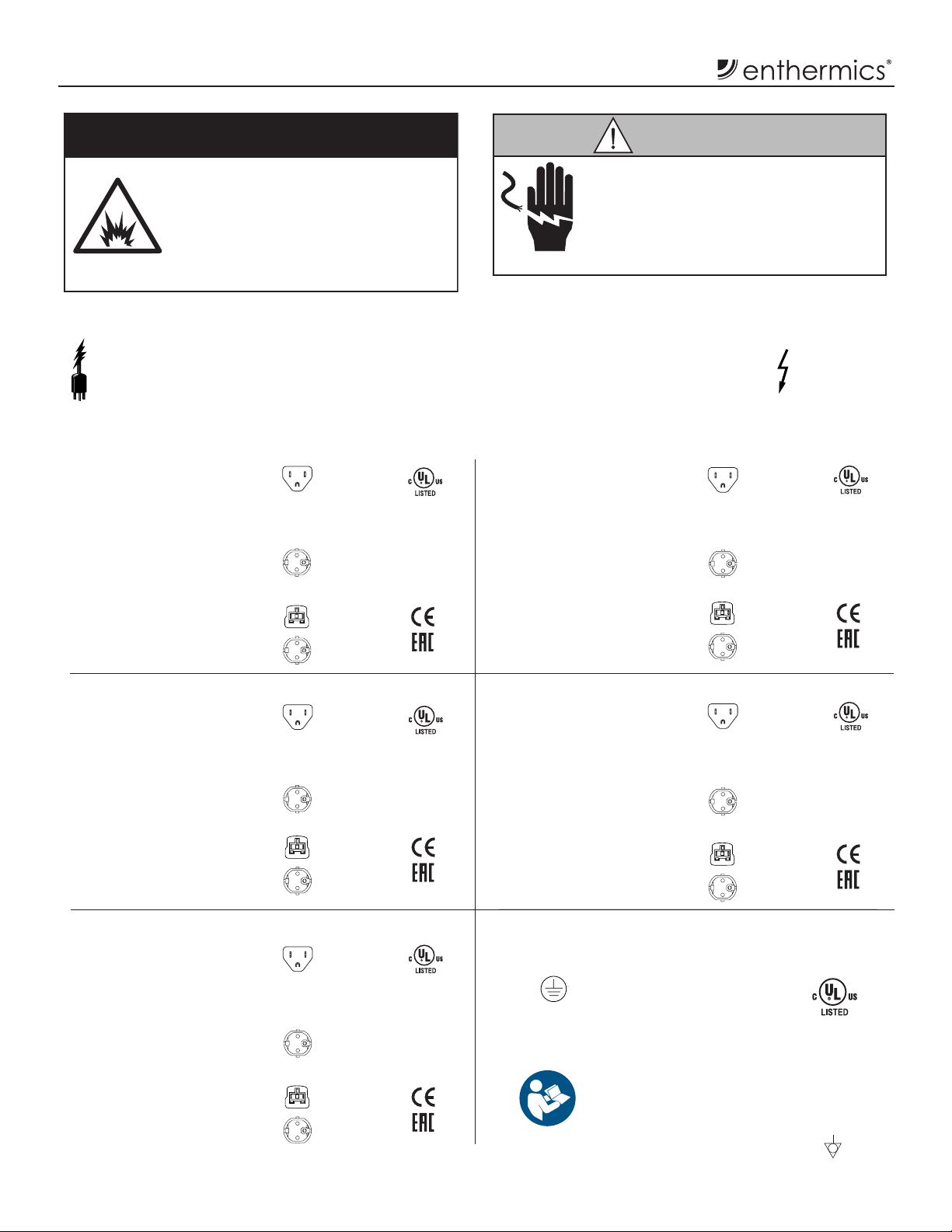
Locate Rating Tag
Verify power requirements. The power speci cation is located on the appliance identi cation
rating tag. This tag is permanently attached to the appliance.
Power Requirements
DC150 DC400
15A - 125V Plug
Safety Class I Equipment
No Applied Parts
Mode of Operation: Continuous
Type B Equipment
Hospital Grade
220-230V Plug
BS 1363 Plug*
(UK only)
CEE 7/7*
220-230V Plug
E471516
IPX-0
Power source must match voltage identified
on appliance rating tag. The rating tag
provides essential technical information
required for any appliance installation,
maintenance or repairs. Do not remove,
damage or modify the rating tag.
Safety Class I Equipment
No Applied Parts
Mode of Operation: Continuous
Type B Equipment
Voltage Present
15A - 125V Plug
Hospital Grade
220-230V Plug
BS 1363 Plug*
(UK only)
CEE 7/7*
220-230V Plug
Hazardous
E471516
IPX-0
DC250 DC750
15A - 125V Plug
Safety Class I Equipment
No Applied Parts
Mode of Operation: Continuous
Type B Equipment
DC350
Safety Class I Equipment
No Applied Parts
Mode of Operation: Continuous
Type B Equipment
Type B Equipment
6
MN-37072 • Rev 2 • 05/16 • Designer Series Blanket Warmer
Hospital Grade
220-230V Plug
BS 1363 Plug*
(UK only)
CEE 7/7*
220-230V Plug
15A - 125V Plug
Hospital Grade
220-230V Plug
BS 1363 Plug*
(UK only)
CEE 7/7*
220-230V Plug
E471516
IPX-0
E471516
IPX-0
15A - 125V Plug
Safety Class I Equipment
No Applied Parts
Mode of Operation: Continuous
Type B Equipment
Grounding reliability can only be achieved when appliance is
connected to an equivalent receptacle marked “Hospital Grade.”
Medical Equipment classi ed by Underwriters
Protective Earth
Ground Symbol
Laboratories with Respect to Electrical Shock,
Fire and Mechanical Hazards only, in Accordance
with UL 61010–1 and CAN/CSA C22.2 No. 61010–1.
electrical shock hazard between the appliance and
other appliances or metal parts in close vicinity,
an equalization-bonding stud is provided. An
equalization bonding lead must be connected to
this stud and the other appliances/metal parts
to provide sufficient protection against potential
difference. The terminal is marked with the
Hospital Grade
220-230V Plug
BS 1363 Plug*
(UK only)
CEE 7/7*
220-230V Plug
E471516
E471516
IPX-0
Electrical Information
Guidance and Manufacturer’s Declaration
The appliance requires special precautions
regarding EMC (Electromagnetic
Compatibility) and needs to be installed
and put into service according to the
EMC information provided in the
accompanying documents.
Portable and mobile RF communications equipment can
affect medical electrical equipment.
A risk of increased emissions or decreased immunity
Electromagnetic Emissions
The appliances are intended for use in the electromagnetic environment speci ed below. The customer or the end
user of this appliance should assure that it is used in such an environment.
Emissions test Compliance Electromagnetic environment - guidance
RF emissions; CISPR 11 Group 1 The appliance uses RF energy only for internal function.
Therefore, its RF emissions are very low and are not likely to cause
any interference in nearby electronic equipment.
RF emissions; CISPR 11 Class B The appliance is suitable for use in all establishments, including
domestic establishments and those directly connected to the public
Harmonic emissions; IEC 61000-3-2 Class A
low-voltage power supply network that supplies buildings used for
domestic purposes.
may result if the power cord attached is altered or a
manufacturer supplied power cable is not used.
The appliance should not be used adjacent to or stacked
with other equipment.
Observe to verify normal operation if it is necessary to use
adjacent to or stacked with other equipment.
The essential performance of the appliance is to not
exceed an internal temperature of 180°F / 82°C (+10%) for
blanket warmers or 150°F / 66°C (+10%) for uid warmers.
Voltage uctuations/Flicker
emissions; IEC 61000-3-3
Complies
Electromagnetic Immunity
The appliance is intended for use in the electromagnetic environment speci ed below. The customer or the end user
of this appliance should assure that it is used in such an environment.
Immunity test IEC 60601 test level Compliance level Electromagnetic environment - guidance
Electromagnetic
discharge (ESD)
IEC 61000-4-2
Electrical fast
transient/burst
IEC 61000-4-4
Surge
IEC 61000-4-5
Voltage dips, short
interruptions and
voltage variations on
power supply input lines
IEC 61000-4-11
Power frequency (50/60
Hz) magnetic eld
IEC 61000-4-8
NOTE: UT is the a.c. mains voltage prior to application of the test level.
±6 kV contact
±8 kV air
±2 kV for power
supply lines; ±1 kV
for input/output lines
±1 kV differential
mode; ±2 kV
common mode
<5 % UT (>95 % dip in
UT) for 0.5 cycle
40 % UT (60 % dip in
UT) for 5 cycles
70 % UT (30 % dip in
UT) for 25 cycles
<5 % UT (>95 % dip in
UT) for 5 sec
3 A/m 3 A/m Power frequency magnetic elds should be at
±6 kV contact
±8 kV air
+2 kV for power
supply lines
±1 kV differential
mode; ±2 kV
common mode
<5 % UT (>95 % dip
in UT) for 0.5 cycle
40 % UT (60 % dip
in UT) for 5 cycles
70 % UT (30 % dip
in UT) for 25 cycles
<5 % UT (>95 % dip
in UT) for 5 sec
Floors should be wood, concrete or ceramic tile.
If oors are covered with synthetic material, the
relative humidity should be at least 30%.
Main power quality should be that of a typical
commercial or hospital environment. The
appliance does not have any input/output lines.
Mains power quality should be that of a typical
commercial or hospital environment.
Mains power quality should be that of a typical
commercial or hospital environment. If the
user of the appliance requires continued
operation during power mains interruptions, it
is recommended that the appliance be powered
from an uninterrupted power supply or a
battery.
levels characteristic of a typical location in a
typical commercial or hospital environment.
MN-37072 • Rev 2 • 05/16 • Designer Series Blanket Warmer
7
Electrical Information
fi xed RF transmitters, an electromagnetic site survey should be considered. If the measured fi eld strength in the location in which the appliance is
Electromagnetic Emissions
The appliance is intended for use in the electromagnetic environment speci ed below. The customer or the end user
of this appliance should assure that it is used in such an environment.
Immunity test IEC 60601 test level Compliance level Electromagnetic environment - guidance
Portable and mobile RF communications equipment should
be used no closer to any part of the appliance, including
cables, than the recommended separation distance
calculated from the equation applicable to the frequency of
the transmitter.
Recommended separation distance
Conducted RF
IEC 61000-4-6
Radiated RF
IEC 61000-4-3
3 V/m
150 kHz to 80 MHz
3 V/m
80 MHz to 2.5 GHz
3 V/m
3 V/m
d = [3.5/3] √P
d = [3.5/3] √P 80 MHz to 800 MHz
d = [7/3] √P 800 MHz to 2.5 GHz
where P is the maximum output power rating of the
transmitter in watts (W) according to the transmitter
manufacturer and d is the recommended separation distance
in meters (m).
Field strengths from xed RF transmitters, as determined
a
by an electromagnetic site survey,
compliance level in each frequency range.
should be less than the
b
Interference may occur in the vicinity of equipment marked
with the following symbol:
NOTE: 1. At 80 MHz and 800 MHz, the higher frequency range applies. 2. These guidelines may not apply in all situations.
Electromagnetic propagation is a ected by absorption and reflection from structures, objects and people.
a. Field strengths from fi xed transmitters, such as base stations for radio (cellular/cordless) telephones and land mobile radios, amateur radio, AM
and FM radio broadcast and TV broadcast cannot be predicted theoretically with accuracy. To assess the electromagnetic environment due to
used exceeds the applicable RF compliance level above, the appliance should be observed to verify normal operation. If abnormal performance is
observed, additional measures may be necessary, such as reorienting or relocating the appliance.
b. Over the frequency range 150 kHz to 80 MHz, fi eld strengths should be less than [VI] V/m.
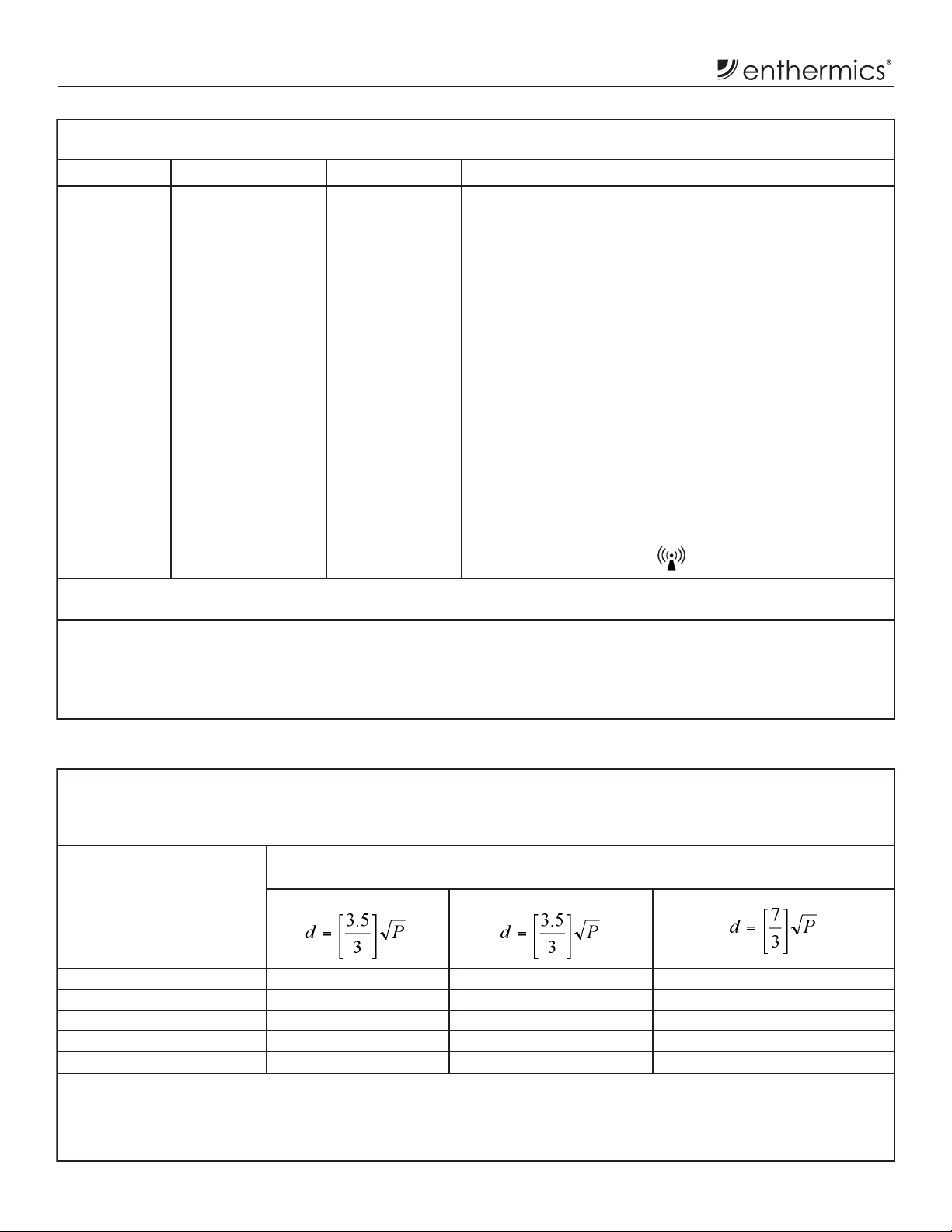
Electromagnetic Immunity Recommended Separation Distance Between Portable And Mobile
RF Communications Equipment And This Unit.
The appliance is intended for use in an electromagnetic environment in which radiated RF disturbances are
controlled. The customer or the user of the appliance can help prevent electromagnetic interference by maintaining a
minimum distance between portable and mobile RF communications equipment (transmitters) and the appliance as
recommended below, according to the maximum output power of the communications equipment.
Separation distance according to frequency of transmitter
Rated maximum output
power of transmitter
150 kHz to 80 MHz 80 MHz to 800 MHz 800 MHz to 2.5 GHz
W
0.01 0.117 0.117 0.233
0.1 0.369 0.369 0.738
1 1.167 1.167 2.333
10 3.689 3.689 7.379
100 11.667 11.667 23.333
For transmitters rated at a maximum output power not listed above, the recommended separation distance d in meters (m) can be estimated using
the equation applicable to the frequency of the transmitter, where P is the maximum output rating of the transmitter in watts (W) according to the
transmitter manufacturer.
NOTE: 1. At 80 MHz and 800 MHz, the separation distance for the higher frequency range applies. 2. These guidelines may not apply
in all situations. Electromagnetic propagation is a ected by absorption and reflection from structures, objects and people.
m
8
MN-37072 • Rev 2 • 05/16 • Designer Series Blanket Warmer
Operation Instructions
Blanket Electronic Control Features
The following refers to features that are available when the electronic control is powered on.
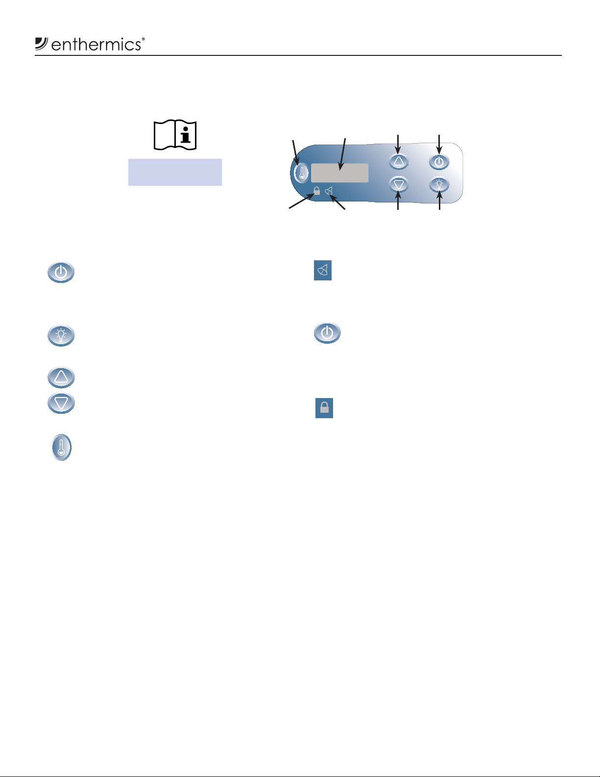
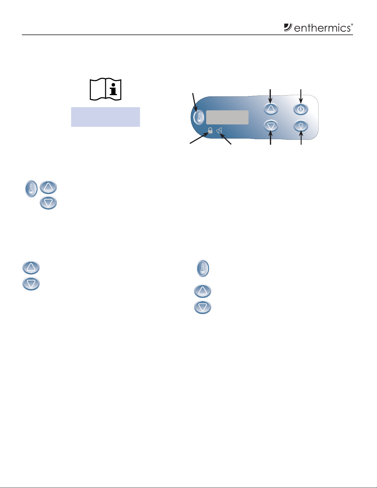
Electronic Control Panel
changes can be made to the temperature set-point
Electronic Control and LED Display
Temperature
Recall Button
LED Digital
Display
Temperature Range:
32°C-71°C (90°F-160°F)
Up Arrow
Button
On/Off
Button
On/Off Button
Press the On/Off button to power on the
electronic control. Press and hold the
On/Off button for three (3) seconds to power
the electronic control off.
Interior Light Button
Press the Interior Light button to toggle blue
interior LED light intensity to high, low, or off.
Up Arrow/Down Arrow Buttons
Used to increase or decrease the temperature
set-point. Additionally used to set the current to
increase or decrease time, date, auto-start, and
auto-stop times.
Temperature Recall Button
Press the Temperature Recall button to view
the actual temperature captured with the
cavity sensor. The display will show the actual
cavity temperature for fi ve (5) seconds before
reverting back to displaying the current
temperature set-point.
LED Digital Display
The control has a four-digit LED display.
Button Lockout
Indicator Light
Error
Indicator Light
Down Arrow
Button
LED Display Status Indicators
Error Indicator Light
This indicator will illuminate and an alarm will
sound if the electronic control senses an error has
occurred (see troubleshooting guide). The alarm
can be muted by pressing the on button.
Error Acknowledgement
To clear or acknowledge an error, press the
On/Off button. Press the On/Off button to
acknowledge the periodic alarm. If the alarm
continues or returns, the appliance is still
experiencing an error and may need service.
Button Lockout Indicator Light
The electronic control can be locked so that no
or the mode selection. Press and hold the
On/Off button and the Up Arrow button at the
same time. The lock indicator will illuminate.
Attempts to operate the on/off button, or
to change the temperature set-point will be
unsuccessful. To unlock the electronic control,
press and hold the On/Off button and the Down
Arrow button at the same time. The electronic
control will unlock, and the lock indicator will
go out.
Power Fail Detection
If the power were to fail for any reason while electronic
control is powered on, the electronic control will retain
in memory its current operating state. When the power
is restored, the electronic control alarms once and
resumes operating in its previously set mode. The on/
off status indicator will blink, alerting the operator that
such an event has occurred. Press the On/Off button
once to acknowledge that the power has been restored.
Interior
Light Button
NOTE: If the timer option is installed, the appliance must
be off for more than 60 seconds to signal a power
failure alarm. When acknowledging a power
interruption, the display will show the length of
time in hours and minutes that the control has
been off due to the power outage.
MN-37072 • Rev 2 • 05/16 • Designer Series Blanket Warmer
9
Operation Instructions
Blanket Electronic Control Features (continued)
Temperature Range:
32°C-71°C (90°F-160°F)
Temperature Format Selection
While the electronic control is in off
state, press and hold the Temperature
Recall button for four (4) seconds to
display the current temperature scale.
Press the Up Arrow or Down Arrow
buttons to switch between °F (fahrenheit)
or °C (celsius).
Sound Function
(Prior to September 2015)
The sound function can be turned on or off.
1. While the appliance is off, press and hold the
Down Arrow button for four (4) seconds.
2. The display will indicate the current sound
status, 0 (off) or 1 (on). Press the Up Arrow
or Down Arrow button to toggle between the
two choices.
Electronic Control and LED Display
Temperature
Recall Button
Button Lockout
Indicator Light
(A er September 2015)
Error
Indicator Light
The sound volume can be changed:
1. While the appliance is on, press the
Temperature Recall button and the Down
Arrow button to display the current volume
setting. Release.
2. Press the Up Arrow or Down Arrow button to
adjust the volume. Volume settings range from
0 (mute)to 12 (loud).
NOTE: The alarm volume is set at the maximum
Up Arrow
Button
Down Arrow
Button
Light Button
(12) and can not be disabled.
On/Off
Button
Interior
10
MN-37072 • Rev 2 • 05/16 • Designer Series Blanket Warmer
Operation Instructions
Optional Timer Control Feature
NOTE:
The appliance time must be manually reset for daylight
The times are displayed in 24-hour format (hh:mm).
If the display has changed due to user interaction, the
If the start and stop times are the same, the appliance
The timer option must be off to reset the appliance time.
An E-60 error is displayed if the clock is not set or
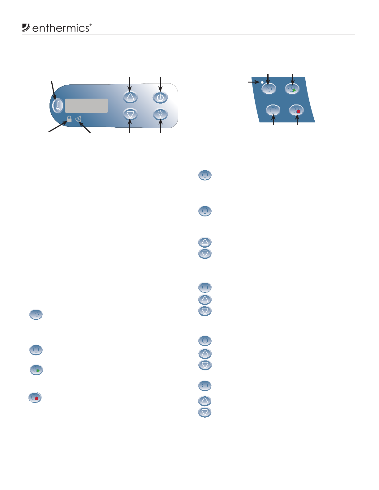
Timer Control Panel
Electronic Control and LED Display
Temperature
Recall Button
Button Lockout
Indicator Light
Error
Indicator Light
Up Arrow
Button
Down Arrow
Button
If the appliance is not equipped with this optional
automated timer feature or it is not in use this section
can be skipped.
saving time.
Midnight is 00:00. Noon is 12:00. 1:00 P.M. is 13:00.
display will reset a er five (5) seconds of inactivity.
will recognize the off time only and will not turn on
without user intervention. This is the best way to set the
warmer for the days when it is not needed.
On/Off
Button
Interior
Light Button
Optional Timer Control
Timer On/Off
Button
On/Off
Indicator
Light
Time Button
Resetting the Time
1. Acknowledge E-60 error
a. Press the Time button to acknowledge the
E-60 error displayed when the control has
been inactive.
2. View and adjust time
a. Press and hold the Time button for four (4)
seconds until the auto-timer on/off indicator
light blinks slowly and the display shows the
current set time.
b. Press the Up Arrow or Down Arrow button to
adjust the time in increments of one (1) minute
or press and hold the Up Arrow or Down Arrow
button to adjust the minutes more quickly.
Set or View
Start Time Button
Set or View
Stop Time Button
the control has been off too long and the memory
has become corrupted.
Press the Timer On/Off button to initiate the
automatic start/stop timer operation. The on/off
indicator light next to this button will illuminate
when the timer is turned on.
Press the Time button to view the current time,
date, and day and initiate changes to the settings.
Press the Start Time button to view the current
automatic start time and initiate changes to
the set time.
Press the Stop Time button to view the current
automatic stop time and initiate changes to
the set time.
3. View and adjust year
a. Press the Time button again to view or set
the year.
b. Press the Up Arrow or Down Arrow button to
adjust the year. The year will always adjust by
one (1).
4. View and adjust date
a. Press the Time button again to view or set
the date.
b. Press the Up Arrow or Down Arrow button to
adjust the date.
5. View and adjust day code (optional)
a. Press the Time button again to set the day
code (d1-d7).
b. Press the Up Arrow or Down Arrow button to
adjust the day code.
NOTE: Setting the day code is optional unless the user
configures the auto-timer to start or stop at a
diff erent time for each day of the week. Typically
Monday=d1, Tuesday=d2, etc.
MN-37072 • Rev 2 • 05/16 • Designer Series Blanket Warmer
11
Operation Instructions
Optional Timer Control Feature (continued)
Same Start and Stop Times for the Week
Note:
Activating this mode overrides all individual
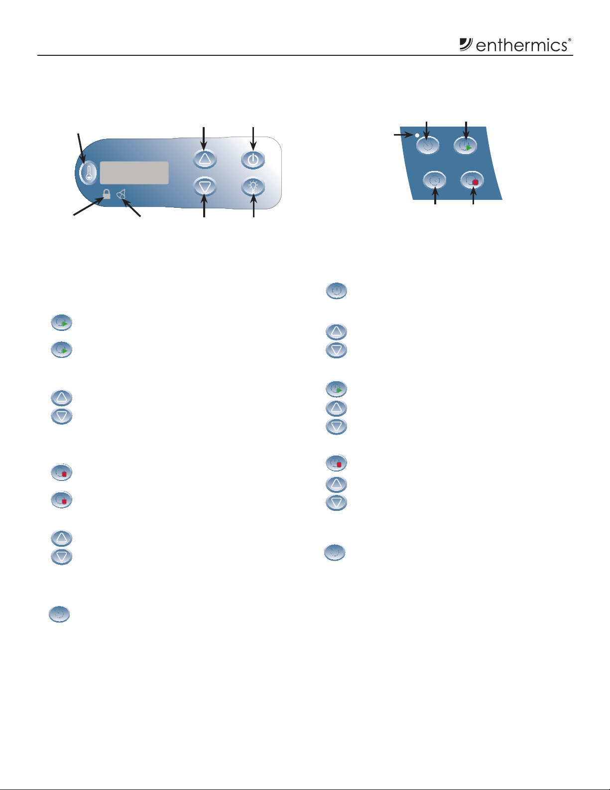
Electronic Control and LED Display
Temperature
Recall Button
Button Lockout
Indicator Light
Error
Indicator Light
The timer option must be off to set the start time.
day programming.
1. View and adjust start time
a. Press the Start Time button to view the start
time for that day.
b. Press and hold the Start Time button for four
(4) seconds to set the current day’s start time
as the same time for every day of the week.
The on/off indicator light will blink slowly.
c. Press the Up Arrow or Down Arrow button
to change the default start time minutes.
Press and hold the Up Arrow or Down Arrow
button to adjust the hour.
2. View and adjust stop time
a. Press the Stop Time button to view the stop
time for that day.
b. Press and hold the Stop Time button for four
(4) seconds to set the current day’s stop time
as the same time for every day of the week.
The on/off indicator light will blink slowly.
c. Press the Up Arrow or Down Arrow
button to change stop time. Press and
hold the Up Arrow or Down Arrow button
to adjust the hour.
3. When both times are set, allow the on/off indicator
light to extinguish and then press and hold the
Timer On/Off button until the on/off indicator
light stays on steadily.
Up Arrow
Button
Down Arrow
Button
On/Off
Button
Interior
Light Button
Optional Timer Control
Set or View
Start Time Button
Set or View
Stop Time Button
On/Off
Indicator
Light
Timer On/Off
Button
Time Button
Different Start and Stop Times for Each Day of
the Week
1. View and adjust specifi c day
a. Press and hold the Time button for eight (8)
seconds. The on/off indicator light will
blink rapidly. The display will show the
current day.
b. Adjust the day by pressing the Up Arrow or
Down Arrow button.
2. View and adjust start time for that day
a. Press the Stop Time button to display the
start time for that day.
b. Press the Up Arrow or Down Arrow button
to adjust the automatic start time.
3. View and adjust stop time for that day
a. Press the Stop Time button to display the
start time for that day.
b. Press the Up Arrow or Down Arrow button
to adjust the automatic stop time.
4. Repeat steps 1-3 for each day of the week
5. When all days and times are set, allow the on/off
indicator light to extinguish and then press and
hold the Timer On/Off button until the on/off
indicator light stays on steadily.
12
MN-37072 • Rev 2 • 05/16 • Designer Series Blanket Warmer
 Loading...