

Page 1
SIVI SEVÝYE KONTROL RÖLELERÝ
SSRC-04
Teknik Bilgi
Ýþletme Aralýðý (DU) : Lütfen cihaz etiketlerine bakýnýz.
: 190-260 V AC
: 340-460 V AC
Ýþletme Frekansý (f) : 50/60 Hz
Çýkýþ Kontaklarý : 1 C/O, 8A, 2000 VA, Cosj=1
Hassasiyet (R(kW)) : Ayarlanabilir 5-50 kW
Ýkaz Iþýðý : Out LEDi
Ortam Sýcaklýðý : -5 °C ; + 50 °C
Baðlantý Þekli : Pano içine dikey veya klemens rayýna
Boyutlar : Tip PK 25
Tip PK 28
Koruma Sýnýfý : IP 20
Aðýrlýk : 0.2 kg
Klemens Kablo Kesitleri : (PK-28 için)
4
mm²
(12AWG) stranded/örgülü rijit kablo
6
mm²
(10AWG) solid/som iletken kablo
2x2.5
mm²
(14AWG) solid/som iletken kablo
(PK-25 için)
4
mm²
(12AWG) solid/som iletken kablo
2,5
mm²
(14AWG) stranded/örgülü rijit kablo
2x1,5mm2 (2x16AWG) solid/som iletken kablo
A4986/Rev.1
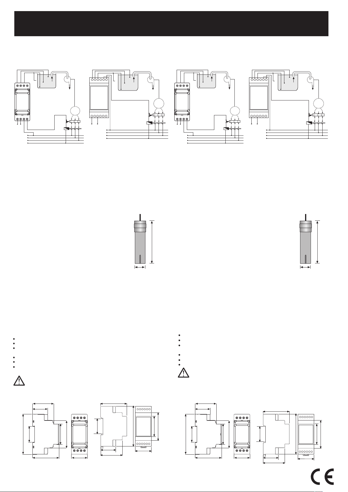
Operation Principles
See above connection diagram for SSRC-04
The output contact switches ON when the liquid reaches the upper level electrode
(U). The output contact switches OFF when the lower level electrode (L) is no longer
in contact with the liquid (in order to prevent the system to work with empty containers).
B (Terminal 8) has to be connected to the container in order to determine the bottom
level accurately. If the container is made of a non conductive material, an additional
electrode connected to B (Terminal 8) must be used. R(kW) (i.e., impedance between
electrodes) can be adjusted to 5-50 kW for different liquids by means of the knob on
the front panel. The Out LED on the front panel lights when the relay is ON position.
NOTE: This controller can not be used with flammable liquids.
Dimensions
Precautions For Installation And Safe Use
Failure to follow those instructions will result in death or serious injury.
Disconnect all power before working on equipment.
When the device is connected to the network, do not remove the front panel.
Do not try to clean the device with solvent or the like. Only clean the device
with a dried cloth.
Verify correct terminal connections when wiring.
Electrical equipment should be serviced only by your compedent seller.
Mount device to the panel.
No responsibility is assured by the manufacturer or any of its subsidiaries
for any consequences arising out of the use of this material.
Sývý Seviye
Elektrodu
8 cm
1.5 cm
Güvenli Kullaným ve Kurulum Ýçin Uyarýlar
Aþaðýdaki talimatlara uyulmamasý halinde yaralanma veya ölümle sonuçlanabilecek
durumlar ortaya çýkabilir.
Cihaz üzerindeki herhangi bir iþlemden önce tüm besleme gerilimlerini kesiniz.
Cihaz þebekeye baðlý iken ön paneli çýkarmayýnýz.
Cihazý solvent veya benzeri maddelerle temizlemeyiniz. Cihazý temizlemek için
sadece kuru bez kullanýnýz.
Cihazý çalýþtýrmadan önce baðlantýlarýnýn doðru olduðunu kontrol ediniz.
Cihazý panoya monte ediniz.
Cihazýnýzdaki herhangi bir sorunda yetkili satýcýnýzla temas kurunuz.
Yukarýdaki önlemlerin uygulanmamasý sonucu doðabilecek istenmeyen
durumlardan üretici firma hiç bir þekilde sorumlu tutulamaz.
TiP PK28
48 mm
34 mm
90 mm
35.3 mm
59.7 mm
45.4 mm
61.8 mm
36 mm
TiP PK25
35 mm
90 mm
45 mm
62 mm
58 mm
32 mm
48 mm
35 mm
Boyutlar
Baðlantý Þemasý PK-28
Kullaným ve Çalýþma Prensibi
Yukarýdaki baðlantý þemalarýna bakýnýz.
Çýkýþ rölesi, iletken sývý üst seviye elektroduna (U) ulaþtýðýnda çeker ve alt seviye
elektrodunun (L) sývý ile temasý kesildiðinde býrakýr (pompa motorunun boþ tank ile
çalýþmasýný önlemek için). B terminali, taban seviyesini hassasiyetle belirleyebilmek
için tankýn gövdesine baðlanmalýdýr. Eðer tank iletken olmayan bir malzeme ile
yapýlmýþsa, B terminaline bir elektrod baðlanmalýdýr. R(kW) (elektrodlar arasý empedans)
deðiþik sývýlar için 5-50 kW deðerlerine ön paneldeki bir düðme yardýmýyla ayarlanabilir.
Röle çekili iken ön paneldeki Out LEDi yanar.
NOT : Bu röle yanýcý sývýlarda kullanýlamaz.
Genel
Sývý seviye kontrol röleleri endüstriyel tesislerde ve yerel kullanýmlarda yer alan
depolardaki iletken sývýlarýn boþaltýlmasýný kontrol etmede kullanýlýrlar.
Baðlantý Þemasý PK-25
LIQUID LEVEL CONTROLLERS
SSRC-04
Connection Diagram Type PK-28
General
Liquid level controllers are commonly used for the level and discharge control of
conductive liquids in tanks located in industrial plants and domestic applications.
Connection Diagram Type PK-25
Operating Range (DU) :Please look at labels on the device.
: 190-260 V AC
: 340-460 V AC
Rated Frequency (f) : 50/60 Hz
Output Contacts : 1 C/O, 8A, 2000 VA, Cosj=1
Sensitivity (R(kW)) : Adjustable 5 - 50 kW
Warning Light : Out LED on the front panel
Ambient Temperature :-5 °C to + 50 °C
Installation : Surface mounting or on
the mounting rails.
Dimensions : Type PK 25
Type PK 28
Protection Class : IP 20
Weight : 0.2 kg
Terminal Cable Crosssections :(for PK-28)
4
mm²
(12AWG) solid conductor
6
mm²
(10AWG) stranded rigid conductor
2x2.5
mm²
(14AWG) solid conductor
(for PK-25)
4
mm²
(12AWG) solid conductor
2,5
mm²
(14AWG) stranded rigid conductor
2x1,5
mm²
(2x16AWG) solid conductor
Technical Data
TiP PK28
48 mm
34 mm
90 mm
35.3 mm
59.7 mm
45.4 mm
61.8 mm
36 mm
TiP PK25
35 mm
90 mm
45 mm
62 mm
58 mm
32 mm
48 mm
35 mm
P
B
U
T
M
C
1
3 ~
L1
L2
L3
N
L
2
1
4
A B
U(5)L(6)
B(8)
Un
SSRC-04
U
A1A2 1
SSRC-04
5L6B8 2
4
Un
P
B
U
T
M
C
1
3 ~
L1
L2
L3
N
L
P
B
U
T
M
C
1
3 ~
L1
L2
L3
N
L
2
1
4
A B
U(5)L(6)
B(8)
Un
SSRC-04
U
A1A2 1
SSRC-04
5L6B8 2
4
Un
P
B
U
T
M
C
1
3 ~
L1
L2
L3
N
L
Liquid Level
Electrode
8 cm
1.5 cm
Bu ürün, 30.05.2008 tarih ve 26891 sayýlý resmi gazetede yayýnlanan
EEE Yönetmeliðinin Madde 2 ve Ek-1A madde 9 kapsamýndadýr.
Vertrieb durch TDE Instruments GmbH
 Loading...