

Page 1
POWER FACTOR CONTROLLER
RG-6B/BS/8B/BS/12B/BS
DIMENSIONS
Do not use device without checking terminal connections.
CONTROLS and OPERATIONS
Capacitor values are recognized and saved with ASEt operation. For doing this, enter
program menu on the device and find ASEt menu. ASEt menu includes 2 parameters
which are S-oF and S-on.
When S-on is selected and SET button is pressed; the device will find and correct
any connection failures (such as wrong connection at voltage and current inputs) first
and then recognize all capacitor steps. If 10th program (PS-10) is selected, all capacitor
powers will be measured. In other programs, only first capacitor step power is measured
and other capacitor steps are calculated and recorded according to selected program.
If S-oF is selected and SET button is pressed during capacitor recognition, automatic
recognition will be ended.
Note: If there are loads other than compensation on the system, the device may
find the connection after several tries. If the device doesnt complete the automatic
connection process, it cant do the step calculation process. In order to have
correct power values for capacitor steps, current and voltage transformer ratios
must be entered correctly. If current and voltage transformer ratios are not entered,
these ratios are assumed to be 1 and capacitor powers are calculated according
to these values (Refer to VT and CT ratio settings).
If automatic setup is selected as S-on, automatic mode starts immediately
without waiting to escape from the menu.
Note: A parameter that is calculated automatically by the device can be changed
by the user.
Automatic Capacitor Recognition and Phase Setup Mode
1
For proper operation, current and voltage connections must be connected as
shown in the connection diagram.
After current and voltage terminal connections, capacitor steps connection must
be done according to the connection diagram.
Lastly, computer communication connection must be done.
Do not power-up the device before verifying terminal connections.
1. RG-B/BS Series Connection
a)
b)
c)
d)
Device can detect wrong connection on the way of active power. For correcting connection
fault, automatic setup must be done or suitable phase value must be programmed from AngL
menu, which is for programming phasor angle, from transformer menu. When user does
automatic setup (ASEt), device will open and close 3 phase capacitor in 1st step during
correction of connection failure. Sudden changes in loads and nonlinear loads (Thyristor or
triac controlled frequency inverter, UPS etc.) existing, automatic setup may not be done. In
this condition, user should disconnect the device and restart it and make the same operation.
This operation can do with selecting S-on under ASEt menu. In this case device corrects
the errors and then calculates the capacitor values.If user does not want calculating capacitor
values, selecting S-oF parameter provides this.
User must enter capacitor values after entering current and voltage transformer ratios. Capacitor
values can be calculated automatically or maually. Capacitor powers are measured automatically
by entering S-on under devices ASEt setting (for details please look Operating Mode
Settings). If 10th program (PS-10) is selected in program menu, all capacitor values are
measured by switching on/off of the capacitors in sequence. In this program, 3 phase capacitors
can be connected as desired according to system requirements. If capacitor steps have been
calculated as in the previous step, this step is not necessary. Selecting other program condition
device only calculate 1st step and other steps will be calculated according to selected program.
Device calculates the capacitor values which will be switched ON according to selected
program; so device switches on/off the required steps.
Connection of circuit breaker or automatic fuse between the network and RG-B/BS series
is highly recommended. Circuit breaker must be in close proximity to the device.
All used fuses must be FF type and the current values of the fuses must be 2A or 3A and
6A (Refer to Connection Diagram).
Generator input must be done only when the network is supplied by the generator. Otherwise
device will be switched to the generator position for each generator starts including the
maintaining purpose.
a)
b)
c)
d)
e)
2.
Commissioning
RG-B/BS Series
Generator Input
When 110-250 V AC connection is connected to devices generator input, COS1
position will be passive and COS2 will be active. So, compensation will be done
according to target COS2 as long as a voltage is present at generator input.
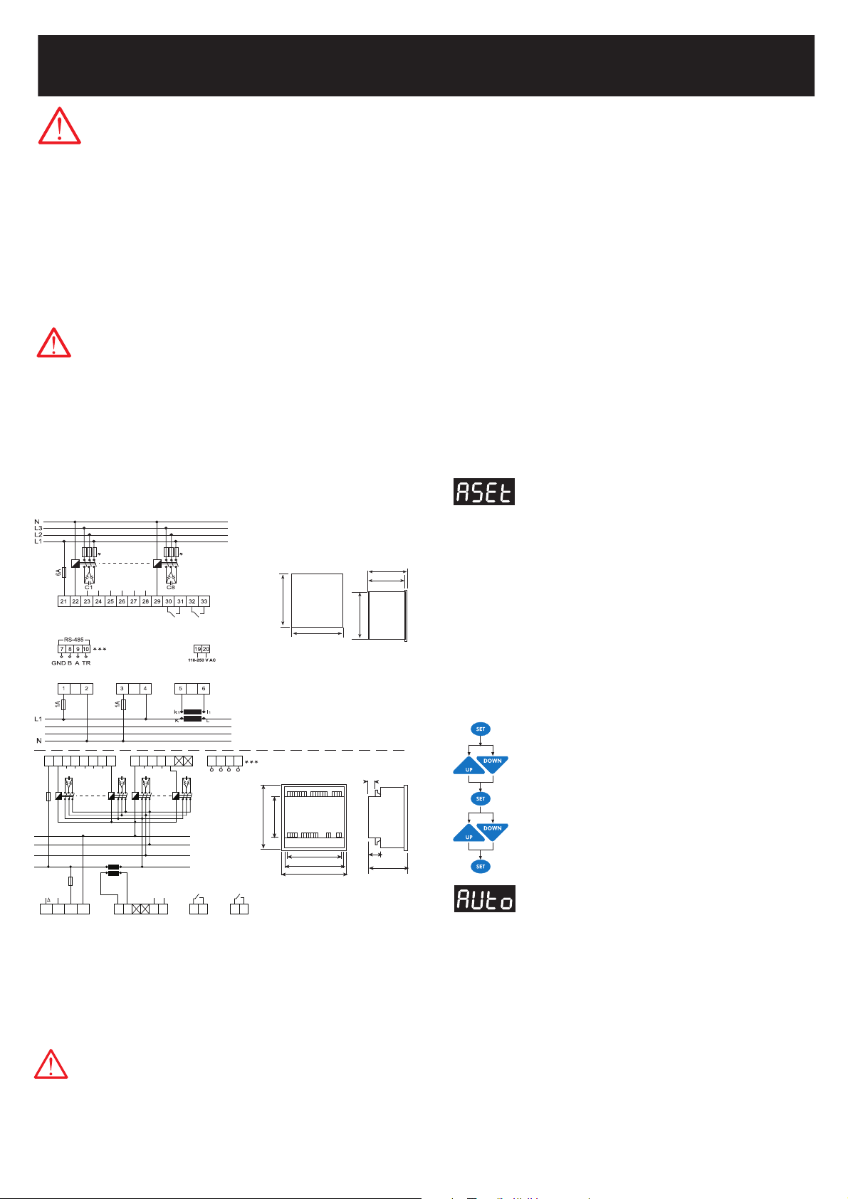
CONNECTION DIAGRAM
Press SET button and enter ASEt menu (S-oF is displayed)
Select S-on option by using UP/DOWN buttons.
(This parameter should be selected as ON in order to start the
Automatic Capacitor Recognition.)
Press SET button in order to activate your selection.
Press SET button 3 sec. and select Auto option.
Select ASEt parameter by using UP/DOWN buttons.
Operating Mode (Automatic/Manual Mode) Settings
RG-B/BS series has two operating modes which are automatic mode and manual
mode. Operating mode can be selected by selecting A-on (automatic) or A-oF
(manual) option. Manual mode is used for test purpose. In this mode, capacitor steps
are switched on&off to test the relay outputs of the device. In the manual mode,
capacitor steps are switched on by pressing SET button and also capacitor steps
are switched off by pressing ESC button. Factory set values for switching on (ond)
and switching off (oFd) time is 10 seconds. These time values can be programmed
in the Delay (dELy) menu (Refer to delay time setting). In the manual mode, step
numbers, which will be switched on&off, can be programmed in Step menu (Refer
to step number setting). Even if manual mode is selected, after 5 minutes, device
starts to work in automatic mode and continues to operate in automatic mode.
When automatic mode is selected, AUTO/MAN LED lights on continuously.
When manual mode is selected, AUTO/MAN LED blinks.
Warning: Device warns user by blinking (short ON, long OFF) the capacitor steps
which will be switched on. Also device warns user by blinking (long ON, short
OFF) the capacitor steps which will be switched off.
For switching capacitors; voltage inputs must be connected and measured
voltage must be higher than (min. 0.5 times) programmed nominal network
voltage.
* Current value of 3-Fuses, which are connected to protect the capacitors, is
chosen according to the nominal current value of capacitors.
** At 3 phase 4 wire applications L1 and Neutral must be connected devices
voltage measurement inputs, at 3 phase 3 wire applications L2 and L3 phases
must be connected. L1 phases current transformer must be connected to
current measurement input. If load is unbalanced, current cable which is
nearest value of total average value must be connected to current transformer.
In this condition voltage inputs must be set refer to current. When device
programmed to automatic setup, it will program suitable phase angle. So it
will measure true values and true compensation.
*** Communication terminals are only available in BS models.
Precautions for Safe Use and Installation
This user manual is prepared for quick commisioning and operating
of the device. Please read this manual carefully before commisioning
or operating RG-B/BS series
Maintenance, installation and operation of RG-B/BS series must be performed
only by the qualified technicians.
RG-B/BS series is connected to the network with current transformer. Do not
disconnect the current transformer terminals. If you disconnect them, be sure
to short-circuit or connect them to another parallel load which have low impedance.
In case of failure, dangerously high voltage at the secondary side of current
transformer may cause an electric shock.
Device is suitable only for panel mounting.
Verify terminal connections when wiring.
Do not use this product for any other purpose than its original task.
Do not operate undervoltage.
When device is connected to the network, do not remove the front panel.
Do not open the RG-B/BS series housing. There are no user servicable parts
inside it.
Do not clean the device with solvent or similar items. Only clean with a dry cloth.
Electrical equipment should be serviced only by your competent seller.
1)
2)
3)
4)
5)
6)
7)
8)
9)
10)
No responsibility is assured by the manufacturer or any of its subsidiaries
for any consequences arising out of the use of this material.
1) Panel cut-out dimension must be 91 mm x 91 mm for Type PR19 and 143 mm x
143 mm for Type PR16.
2) Before installation, remove the mounting brackets.
3) Mount the device to front panel.
4) Insert the mounting brackets.
5) Wire thickness for voltage and current terminals must be 2,5 mm2, but it is suitable
for cables which have up to 4 mm2 section.
6) CAT5 cable is recommended for RS-485 input terminal.
Excessive force can damage the device.
Turn the screw into the terminals and tighten until the RG-B/BS series is secured
in place.
70mm
79.3mm
90mm
96mm
96mm
Type PR 19
15 17 18 19 20 21 22
5 6 9 10
6A
Alarm Relay
11 12
C1 C6 C7 C12
23 24 25 26 27 30 31 32 33
N
L3
L2
L1
Fan Relay
13 14
1 2 3 4
Un V
in
I
in
Generator
Input
110~250 V AC
16
1A
K L
l1k
1
~ ~
L2
L3
**
**
Type
PR16
(144x144)
143
99
121
138.4
143
18
34.5
67
RG-6B/BS
RG-8B/BS
****
Voltage Measurement
Input
Auxiliary
Supply
Current Measurement
Input
Generator
Input
Fan Relay
Alarm Relay
RG-12B/BS
RG-6B/BS
RG-8B/BS
TR B GNDA
RS485
Page 2
POWER FACTOR CONTROLLER
RG-6B/BS/8B/BS/12B/BS
CURRENT and VOLTAGE TRANSFORMER RATIO SETTINGS,
PHASE ANGLE and NETWORK VOLTAGE PROGRAMMING
In order to have correct power values for capacitor steps, current and voltage transformer
ratios must be entered correctly. Current and voltage transformer ratios are entered
in trF menu. If no value is entered in the menu, these ratios are assumed to be 1
and capacitor powers are calculated according to these values.
Current Transformer Ratio
CT ratio can be programmed between 1 and 2000. This value must be the Current
Transformers ratio.
Exp: For 150 A/5 A current transformer, CT ratio must be entered as "30".
Program Selection
Press SET button for 3 sec.
2
Step Number Setting
The maximum number of steps that the device can control depends on the device
model. It can be 6, 8 or 12 . Each of these steps can be programmed oFF, oN or
Auto in the
10th
program.
AUto : Programming capacitor power (kVAr) menu.
on : Capacitor programmed as a steady.
oFF : Meaning of there is no capacitor connection at output.
When other programs are selected, 1st steps capacitor power can be programmed.
Other steps power can be programmed according to selected program.
* Recommended program mode.
RG-B/BS series has 10 different program modes which determines the power ratio
sequences of capacitor steps. These are given on the tables below.
If capacitors sequence is set just like 2nd program (P-02) (1.1.1.1.....), many identical
connection compenents are required. Selecting between 3th program (P-03) to 8th
program (P-08),less connection components are used (exp: 1.2.2......). 9th program
(P-09) provides different group powers. 9th programs capacitor sequence working
principle is one groups power can be higher than previous groups sums by first
group power. With this method, less capacitors can be used. For 10th program (P-
10), there is no rule of arranging the steps from low to high. With auto setup, capacitor
steps can be calculated automatically or user can enter the capacitor values manually.
User can select used or not used capacitor steps from CAP menu at 10th program.
RG-B/BS series counts the number of switch on/off of every capacitor step and
switches on required steps every time. With this method, it prolongs capacitors life
time duration. Enter your required program by following the steps below.
Press SET button for 3 sec. and select Auto option.
Press SET button and enter AUto menu. (A-on is displayed)
Select A-on or A-oF option by using UP/DOWN buttons.
In order to activate the selection, press SET button.
Press SET button for 3 sec.
Select Prog menu by using UP/DOWN buttons.
Press SET button in order to see preset program number (Exp: 10).
Select desired program number (1-10) by using UP/DOWN buttons
Press SET button to confirm your selection.
Press ESC button until SAVE is displayed.
Press SET button to save your changes or ESC button to exit without
saving.
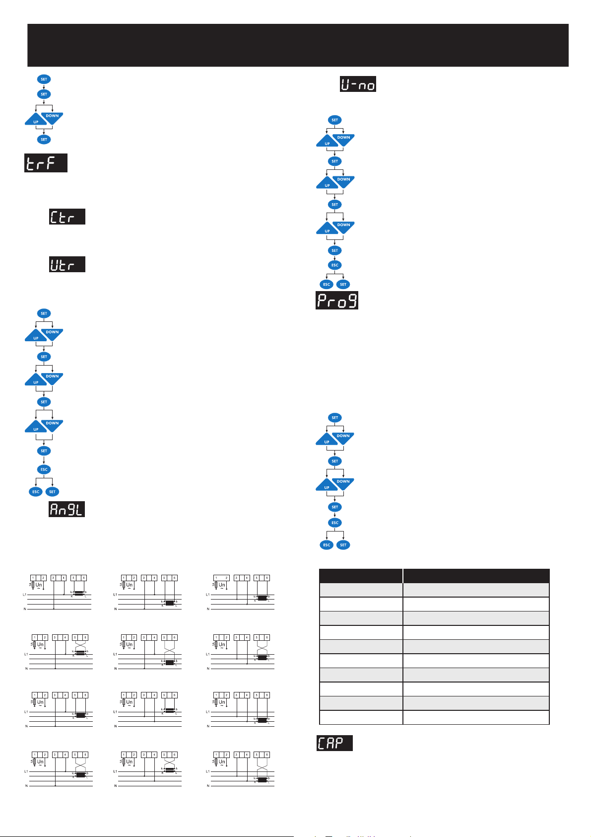
Phase Angle Setting
Phase angle is changed for all possibility of current and voltage connections in this
menu. If user knows phases, which are connected to measurement inputs, phase
angle can be set manually in this menu. Automatic setup (ASEt) is recommended for
this application. At the end of ASEt application, present connection is displayed at
this menu.
-It can be programmed between 0 and 360 in 30 degree differences (0, 30, ...., 330).
Press SET button for 3 sec.
Select trF menu by using UP/DOWN buttons.
Press SET button and select Utr option.
Select An9L/U-no option by using UP/DOWN buttons.
Press SET button to enter Phase Angle / Operating Voltage value.
Enter phase angle between -150° to 180° (programmed 30 degress
differences) or operating voltage value by using UP/DOWN buttons
(Use SET or ESC button to set next digit or previous digit)
Press SET button to confirm your selection.
Press ESC button until SAVE is displayed.
Press SET button to save or ESC button to exit without saving.
Operating Voltage Programming
Nominal voltage of the network where the device is connected in this menu. For insuring
a true compensation, measured voltage value must be higher than min. 0.5 times of
programmed nominal network voltage.
Select trF menu by using UP/DOWN buttons.
Press SET button and select Utr option.
Select Utr / Ctr option by using UP/DOWN buttons.
Press SET button to enter Voltage / Current Transformer Ratio.
Enter VT or CT ratio between 1-2000 by using UP/DOWN buttons.
(Use SET or ESC button to set next digit or previous digit)
Press SET button to confirm your selection.
Press ESC button until SAVE is displayed.
Press SET button to save or ESC button to exit without saving.
Voltage Transformer Ratio
VT ratio can be set between 1-2000. This value must be the Voltage Transformers
ratio.
Exp: For 34,5 KV / 100 V voltage transformer, VT ratio must be entered as 345.
L2
L3
Phase 0°
L2
L3
Phase 180°
L2
L3
Phase 240°
L2
L3
Phase 60°
L2
L3
Phase 120°
L2
L3
Phase 300°
L2
L3
Phase 30°
L2
L3
Phase 210°
L2
L3
Phase 150°
L2
L3
Phase 330°
L2
L3
Phase 270°
L2
L3
Phase 90°
Auxiliary
Supply
Voltage
Measurement
Input
Current
Measurement
Input
Auxiliary
Supply
Voltage
Measurement
Input
Current
Measurement
Input
Auxiliary
Supply
Voltage
Measurement
Input
Current
Measurement
Input
Auxiliary
Supply
Voltage
Measurement
Input
Current
Measurement
Input
Auxiliary
Supply
Voltage
Measurement
Input
Current
Measurement
Input
Auxiliary
Supply
Voltage
Measurement
Input
Current
Measurement
Input
Auxiliary
Supply
Voltage
Measurement
Input
Current
Measurement
Input
Auxiliary
Supply
Voltage
Measurement
Input
Current
Measurement
Input
Auxiliary
Supply
Voltage
Measurement
Input
Current
Measurement
Input
Auxiliary
Supply
Voltage
Measurement
Input
Current
Measurement
Input
Auxiliary
Supply
Voltage
Measurement
Input
Current
Measurement
Input
Auxiliary
Supply
Voltage
Measurement
Input
Current
Measurement
Input
PROGRAM SEQUENCE
01
02
03
04
05
06
07
08
09
*10
linear
1.1.1.1................
1.1.2.2................
1.2.2.2................
1.2.3.3................
1.2.4.4.................
1.1.2.4................
1.2.3.4................
1.2.4.8................
Any sequence can be selected by user.
Available Programs
Page 3

Please look at the rear label of the device
(0.9-1.1)xUn
50mA-5.5A
50 Hz / 60 Hz
1% ±1digit (V,I,Cosj),
2%±1 digit (W, VAr, VA)
<2 VA(Current)
3 VA - 10 VA (Voltage)
5 A, 250 V AC, 1250 VA
110V AC ~ 250 V AC
In case of power failure longer than 20 msec., all capacitor steps are
disconnected automatically.
-0.800 ... +0.800
-0.800 ... +0.800
1 - 2000
1 - 2000
Switching on&off and discharge times can be set seperately
between 2-1800 sec.
6, 8(PR-16, PR-19), 12(PR-16)
Selectable.
-5° C - 55° C
00.0 - 100 °C
Red LED Display with 4 Digits
Double Insulation ( )
2.5 mm
2
IP 00
IP 40 (front panel)
Terminal
Type PR19, Type PR19
91x91 mm(PR-19), 139x139 mm(PR-16)
0.85 kg.(PR-16), 0,45 kg.(PR-19)
1-247
1.200 Kbps, 2.400 Kbps, 4.800 Kbps, 9.600 Kbps, 19.20 Kbps, 38.40 Kbps
no, odd, even
1,000
0,900
P-10
10 sec.
10 sec.
14 sec.
265.0 V AC
3.0 sec.
oF
5.0%
3.0 sec.
oF
25
15
240 hour
55 °C
oF
53 °C
45 °C
40 °C
1
1
0°
230 V
1
9.600 Kbps
no
1234
oFF
Operating Voltage (Un)
Operating Voltage Ratio DU
Operating Current Range DI
Frequency
Measurement Class
Power Consumption
Output Contact
Generator Input
No-Volt Feature
Setting Range
COS1 Setting
COS2 Setting
CT Ratio
VT Ratio
Switching on&off and,
Discharge Time Setting
Step Number
Over Voltage Value
Ambient Temp. Range
Measurement Temp. Range
Display
Equipment Protection Class
Cable Section (for terminals)
Terminal Protection Class
Box Protection Class
Connection Type
Dimension
Panel Cut-out
Weight
RS-485 Communication*
Address
Baud Rate
Parity
Default Factory Settings
Target COS1
Target COS2
Program
t-on (Switching on delay)
t-off (Switching off delay)
Discharge time
Over Voltage
Delay
Step Protection
Over Harmonic
Delay
Step Protection
Inductive Ratio Range
Capacitive Ratio Range
Ratio Time
Temperature Protection
Alarm Value
Step Protection
Lower Alarm
Fan Setting
Operation Temperature
Lower Temp. Value
CT Ratio
VT Ratio
Connection Angle
Nominal Line Voltage
RS-485 Communication
Address
Baud Rate
Parity
Password
Password Activation
Technical Features
:
:
:
:
:
:
:
:
:
:
:
:
:
:
:
:
:
:
:
:
:
:
:
:
:
:
:
:
:
:
:
:
:
:
:
:
:
:
:
:
:
:
:
:
:
:
:
:
:
:
:
:
:
:
:
:
:
:
:
POWER FACTOR CONTROLLER
RG-6B/BS/8B/BS/12B/BS
3
In case of any failure, alarm relay is switched on and alarm led lights.
When measured temperature value increase fan measured value after 10
second fan led light will be on.
The LEDs of the steps that are to be switched on or off. They indicate the
switched on steps for compensation. The LED of the switched on step lights
up.
Indicates if the operating mode is automatic or manual.
(If it is continuously ON, RG-B/BS series operates in Automatic Mode. If it
blinks, RG-B/BS series operates in Manual Mode)
Press SET button for 3 seconds, when Cosj/Auto Setup LED is open,
automatic setup is done. In measurement mode Cosj value is displayed.
Press SET button for 3 seconds, when V / Cosj LED is open COS1 and
COS2 is programmed. In measurement mode voltage value is displayed.
Press SET button for 3 seconds, select PROGRAM/I light to select power
sequence program. In the measurement mode, current values of related
phases are displayed.
Press SET button for 3 seconds, select TIME/W led to set switching on delay
time, switching off delay time and discharge time.
In the measurement mode, active power value is displayed.
Press SET button for 3 seconds, select CAPACITORS/VAr led to set capacitor
values and capacitor connections (AUto, on, oFF).
In the measurement mode, reactive power values are displayed.
Press SET button for 3 seconds, select RESET/VA LED for erasing alarms.
In measurement mode apparent power value is displayed.
Press SET button for 3 seconds, select NETWORK/% LED to set current
transformer ratio (Ctr), Voltage transformer ratio (Vtr), phase angle (AngL)
and capacitor nominal voltage value (U-no) is set. In measurement mode
inductive and capacitive ratio values are displayed as %.
Press SET button for 3 seconds, select ALARM / °C LED to set alarms for
over voltage, reactive/active ratio, temperature and harmonics. In
measurement mode temperature is displayed.
1.
2.
3. 1,2,...,8 LEDs
4. OTO/MAN LED
5. Cosj /Auto Setup LED
6. V / Cosj LED
7. I / Program LED
8. W / Time LED
9. VAr / Capacitor LED
10. VA / Reset LED
11. % / Network LED
12. °C / Alarm LED
:
:
:
:
:
:
:
:
:
:
:
:
Press SET button 3 seconds, select RS-485/THD LED for setting address,
baudrate and parity values for RS-485 communication protocol. In measurement
mode THD values (19th harmonics) is displayed by pressing SET button.
Press SET button 3 seconds, select PIN/ERR LED for setting and changing
password in measurement mode if any error happens this LED will be on (If
there are more than one error, errors code is displayed by pressing SET button).
Go to next menu or increase related value.
Exit from a menu. In the measurement mode, it is used to exit from harmonic
menu.
Enter to a menu or confirm the data entry. In the measurement mode, it is used
to observe the harmonic values of current, voltage and power values.
Go to the previous menu or decrease related value.
This LED represents that RG-B/BS is waiting to switch capacitor steps on.
This LED represents that RG-B/BS wil not switch any capacitor steps on&off
This LED represents that RG-B/BS is waiting to switch capacitor steps off.
If capacitor is not connected to the related step,
lights is ON.
If reactive energy ratios exceed adjusted set values, % led lights.
If voltage harmonic ratios exceed adjusted set values,
led lights.
When the value of voltage exceeds adjusted set value or devices measured the
value of voltage less than 30V or when devices can not measure current during
auto setup, V> light is ON.
Represents measurement values with kilo unit (x10
3
).
Represents measurement values with mega unit (x10
6
).
13. THD / RS-485 LED
14. Err / Pin LED
15. Up Button
16. Esc Button
17. Set Button
18. Down Button
19. C+ LED
20. Normal LED
21. C- LED
22.
23.
24.
25. V>
26. k LED
27. M LED
:
:
:
:
:
:
:
:
:
:
:
:
:
:
:
Delay Time Setting
Switch ON delay (ond), Switch OFF delay (oFd) and discharge time (rC) is
programmed for the steps in this menu.
Delay time can be set between 2 and 1800 seconds in this menu.
Press SET button for 3 sec.
Select dELy menu by using UP/DOWN buttons.
Press SET button and select ond parameter. (Exp:10)
Select ond / oFd / rC option by using UP/DOWN buttons.
Press SET button.
Enter delay time between 2-1800 sec. by using UP/DOWN buttons.
(Use SET or ESC button to set next digit or previous digit)
Press SET button to confirm your selection.
Press ESC button until SAVE is displayed.
Press SET button to save your changes or press ESC button to exit
without saving.
NOTE: Icon explanations are the same for type PR-19 and PR-16 models. The figure
above shows the front panel of PR-19 RG-B/BS 08. The step numbers of the device
shown with number 3 will change according to the model number.
4
27
22
26
31 2
5
6
7
8
9
10
11
12
13
14
15
16
17
18
23
24
25
19
20
21
Page 4

4
A4182/Rev.7
POWER FACTOR CONTROLLER
RG-6B/BS/8B/BS/12B/BS
These programs are set for protecting capacitors by user.
Programmable Alarm Protection
Over Voltage Protection Setup
This protects capacitors from over voltage. It has 3 parameters.
SP-U : It can be programmed between 0-500 V. Setting to 0 means
alarm is turned off.
dELy : Delay time. It can be programmed between 0-999.9 sec.
CAP : It shows step state in alarm condition. Selecting on will cause
the steps to remain the same. Selecting oF will cause to switch off the
capacitor steps.
Over THDV Protection Setup
Device gives an alarm if THDV value exceeds entered set value. It has 3
parameters.
SP-t : THD% can be set between 0-99.9. Setting to 0 means alarm
is turned off.
dELy : Delay time. It can be programmed between 0-9999 sec.
CAP : It shows step state in alarm condition. Selecting on will cause
the steps to remain the same. Selecting oF will cause to switch off the
capacitor steps.
Ratio Protection Setup
Device gives an alarm if the capacitive and inductive ratio exceeds the
value entered by the user in programmed time. It has 3 parameters.
ýnd : Ýnductive ratio can be set between 0-99.9 %. Setting to 0 means
alarm is turned off.
CAP : Capacitive ratio can be programmed between 0-99.9 %. Setting
to 0 means alarm is turned off.
HoUr : Programmed between 1-240 hours.
NOTE : Device shows ýnd and CAP ratios according to programmed
xxx hour, so user can see parameters only for last xxx hours.
Over Heat Protection Setup
After the temperature measured by the device increases the set value and
stays over that value for 10 seconds, device gives an alarm. It has 3
parameters.
SP-H : Temperature alarm turned off down.
SP-L : Back to temperature alarm value can be set between 0-99.9 °C.
A value higher than SP-H can not be used.
CAP : It shows step state in alarm condition. Selecting on will cause
the steps to remain the same. Selecting oF will cause to switch off the
capacitor steps.
This function is used for switching-on and switching-off the fan output
contact according to measured temperature. There are two submenus as
F-on and F-oF.
F-on : This is the assignment menu for programming the switch-on
temperature value. After the temperature measured by the device increases
the set value and stays over that value for 10 seconds, contact will be
switched-on and fan LED will be on. Value can be defined between 00.0-
99.8 °C. If this value is set as 0.00, fan function will be disabled and FoF value will be set as 00.0 automatically.
F-oF : This is the assignment menu for programming the switch-off
temperature value. A value higher than F-on can not be used.
Fan Relay Settings
Monitoring the measured temperature
In order to make a correct measurement, device must be in operation at least 30 min.
In order to observe the measured environmental temperature, press UP/DOWN buttons
untill flashing C°/Alarm LED.
Related Alarm LED is on if any failure is occured for any reason. When
user wants to monitor the errors, UP/DOWN buttons are used until the
E-xx number is displayed. All the error codes are displayed respectively
by pressing the SET button. This parameter is not displayed if there is no
error.
For example, E-07 means over voltage condition error.
Displaying the Alarm Codes which are given by the device
NO DESCRIPTION REASON
00
01
02
03
04
05
06
07
08
09
10
11
12
13
14
15
16
17
18
19
20
21
22
23
24
25
26
27
28
29
ALARM CODES
Optional
Angle between phase voltages doesnt equal to 120°
Reverse phase sequence
One or more phase voltages dont exist
Phase 1 Current
Phase 2 Current
Phase 3 Current
THD for voltage exceeds the preset value
Voltage value of any phase exceeds the preset value
Reactive capacitive ratio exceeds the preset value
Reactive inductive ratio exceeds the preset value
Temperature of the capacitors exceeds the preset value
Automatic connection could not be found
Over compensation
Insufficient compensation
Phase sequence is not correct
Capacitor power for phase 1 is not appropriate
Capacitor power for phase 2 is not appropriate
Capacitor power for phase 3 is not appropriate
Capacitor step 1 is defected
Capacitor step 2 is defected
Capacitor step 3 is defected
Capacitor step 4 is defected
Capacitor step 5 is defected
Capacitor step 6 is defected
Capacitor step 7 is defected
Capacitor step 8 is defected
Capacitor step 9 is defected
Capacitor step 10 is defected
Capacitor step 11 is defected
Capacitor step 12 is defected
Neutral and Voltage terminal connections may be wrong
Voltage terminal connections may be in counter clockwise direction
Voltage terminal connections may be wrong
Current transformer connections for phase 1 may be wrong or fist capacitor step may be defected
Current transformer connections for phase 2 may be wrong or first capacitor step may be defected
Current transformer connections for phase 3 may be wrong or first capacitor step may be defected
Excessive harmonic may be exist in the system
Voltage value of the system may be increased
Compensation Error
Compensation Error
Over Temperature
Defected capacitor step or variable loads
Target Cosj is capacitive even if all capacitor steps are switched off
Capacitor powers are not sufficient for target Cosj
3-phase capacitor powers were not selected properly
Capacitor powers for phase 1 were not selected properly
Capacitor powers for phase 2 were not selected properly
Capacitor powers for phase 3 were not selected properly
In the capacitor step measurement, 3-phase capacitor step is unbalanced or the fuse of any phase is blown
In the capacitor step measurement, 3-phase capacitor step is unbalanced or the fuse of any phase is blown
In the capacitor step measurement, 3-phase capacitor step is unbalanced or the fuse of any phase is blown
In the capacitor step measurement, 3-phase capacitor step is unbalanced or the fuse of any phase is blown
In the capacitor step measurement, 3-phase capacitor step is unbalanced or the fuse of any phase is blown
In the capacitor step measurement, 3-phase capacitor step is unbalanced or the fuse of any phase is blown
In the capacitor step measurement, 3-phase capacitor step is unbalanced or the fuse of any phase is blown
In the capacitor step measurement, 3-phase capacitor step is unbalanced or the fuse of any phase is blown
In the capacitor step measurement, 3-phase capacitor step is unbalanced or the fuse of any phase is blown
In the capacitor step measurement, 3-phase capacitor step is unbalanced or the fuse of any phase is blown
In the capacitor step measurement, 3-phase capacitor step is unbalanced or the fuse of any phase is blown
In the capacitor step measurement, 3-phase capacitor step is unbalanced or the fuse of any phase is blown
LED
 Loading...