

Page 1
NETWORK ANALYSER
MPR-53/53S
8
NETWORK ANALYSER
MPR-53/53S
General
MPR-53/53S is developed for measuring all the electrical parameters on the
network. Measured parameters are shown in 5 separate displays.This allows
to monitor more than 50 parameters at the same time. MPR-53S has also
MODBUS serial interface feature.
Using of MPR-53/53S:
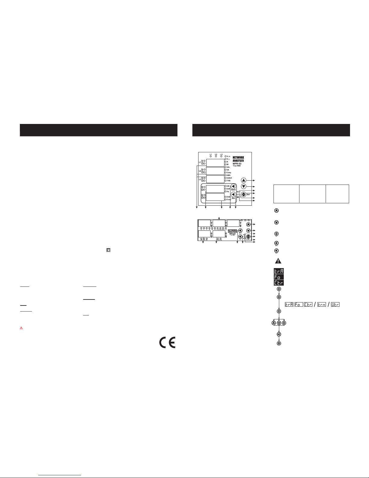
Parameters are shown in L1, L2, L3 displays (VLN; VLL; A; IN; W; VAr; VA; Cosj;
kWh, kVarh, THD) by using up-down buttons. Total Active (SW), Total Apparent
Power (SVA) and Frequency (Hz) are selected by back button.
Total Reactive Power (SVAr) and Cosj are selected by Esc button.
Monitoring of Min.,Max. and Max. Demand Values:
Min. and max. values are defined for VLN, VLL, A, W, VAr, VA, SW, SVAr, SVA;
demand values are defined for A, W, VAr, VA, SW, SVA, SVAr.
If measured instant value is smaller than min. value which was stored before,
it is stored as new min. value. If measured instant value is greater than max.
value which was stored before, it is stored as new max. value.
Demand value is the average value of the measured values in demand time
(15 minute).
If one of defined parameters is displayed (ie. A) when deman button is
pressed min., max or max. demand values are displayed. When an undefined
parameter is displayed (ie. Cosj) if demand button is pressed, instant value
is continued to display.
Monitoring THD Values
When VLN and THD leds light on, voltage THD is monitored and also if A
and THD leds light on, current THD is monitored.
Monitoring Neutral Current
Neutral current can be monitored by scrolling after 3-phases current values
has displayed.
H-L-M LEDs
H-L-M LEDs are dedicated to displaying the min., max. and max. demand
values according to selected parameters.
H: Maximum Value, L: Minimum Value, M: Max. Demand Value
Energy Pulse Outputs
MPR-53/53S has 2 Energy Pulse Outputs. These outputs give the pulses only
for E-1 (Energy Counter).
Pul1 and Pul2: In o-1 (Pulse1), o-2 (Pulse2) menus which are in the pulse
menu, device give pulse according to selected energy parameters as [Active
energy (ACt, A-I, A-E), Reactive energy (rEA, r-L, r-C)].
Please refer to the pulse menu for the coefficients of energies.
In this menu, current transformer ratio is set between 1 - 2000.
Current Transformer Ratio Setup
Note: If the current transformer is not used between the system
and MPR-53/53S, current transformer ratio is entered as 1.
Example: If a current transformer which has a ratio of 250/5A is
used between the system and MPR-53/53S; Current transformer
ratio is entered as 50 (250/5).
Press SET button for 3 seconds (trA Fo menu is displayed)
Press ESC button one by one until SAU E SEt yES is displayed.
Press SET button. When SAU E SEt yES is displayed, if you
press ESC button or choose no option instead of yES option
by using UP-DOWN buttons, new data will be cancelled and
previous value will be activated.
1
Press SET button. Blinking the first digit of displayed value appears.
(trA Fo Utr menu can be programmed similarly.)
Digital Inputs
MPR-53/53S has 2 digital inputs which are used to monitor the status of
electrical contacts. Digital input has 2 functions :
- Enabling remote control of the data received through the digital input terminal
(battery, thermostat, circuit breaker, pumps status)
- Controlling energy counters and determining which energy counter will be
active.
FUNCTIONS OF BUTTONS
In the monitoring mode, it is used to switch between
(V
LN
, VLL, A, W, VAr, VA, Cosj, kWh, kVarh, THD) parameters.
At the programming mode, it provides to increase value of desired
parameter and pass to the next menu.
(Back) In the monitoring mode, it is used to switch between SW, SVA
and Hz parameters. It used to switch to the previous digit in submenu.
In the monitoring mode, it is used to pass between
(V
LN
, VLL, A, W, VAr, VA, Cosj, kWh, kVarh, THD) parameters.
At the programming mode, it provides to decrease value of desired
parameter and pass to the prevides menu.
(SET) In the monitoring mode, it is used to switch between min.,
max., demand and instant values. When it is pressed for 3 seconds,
programming mode it is entered.
In the programming mode, it is used for saving parameters and
moving to the sub menu.
(ESC) In the monitoring mode, it provides to switch between SVAr
and Cosj values. In the programming mode, it is used to enter to
the upper menu or it is used to quit from the programming mode
without saving values.
If user password is activated and set button is pressed for 3
seconds, a pin code is required in order to enter to the menu.
Press SET button; trA Fo Ctr menu is displayed (In CT-25 adapted
devices, trA Fo trn is displayed instead.)
(Not: trA Fo Utr menu can be displayed by scrolling the UP/DOWN
buttons.)
Enter the blinking digit value by scrolling UP/DOWN buttons.
Switch to the other digits by using SET button, use BACK button
to go to previous digit. After you entered the last digit press SET
button, trA Fo Ctr / trA Fo trn / trA Fo Utr is displayed. on
can be selected by scrolling UP/DOWN buttons.
(Data is entered
but is not activated yet. For activating the new data please follow
the below steps).
A3918/Rev.3
Measured Parameters:
VLN (Phase Voltage ) Cosj THD (Total Harmonic Distortion)
V
LL (Phase to Phase Voltage) AI ( kWh) (Import Active Energy I) Hz. (Frequency)
A (Phase Current, Neutral Current) AE (kWh) (Export Active Energy)
S
W (Total Active Power)
W (Active Power) rI (kVArh) (Import Reactive Energy)
S
VAr (Total Reactive Power)
VAr (Reactive Power) rE(kVArh) (Export Reactive Energy)
S
VA (Total Apparent Power)
VA (Apparent Power)
Calculation Methods for Active / Reactive Power Values
If the led on the most left side blinks it represents that active powers / reactive
powers direction is negative.
There are two methods for calculating total active and total reactive powers:
1) Active / Reactive power can be calculated by summing import and export
values and displaying as a single value.
2) Active / Reactive power can be calculated according to direction as
import / export.
Note :
1) The dot at the most right digit of the fourth display (During SW is
displayed) represents that displayed value is export active power value.
Vice versa, displayed value is import active power value.
2) The dot at the most right digit of the fourth display (During SVAr is
displayed) represents that displayed value is capacitive reactive power
value. Vice versa, displayed value is inductive reactive power value.
3) The displayed parameter will not change if power is off after 30 seconds
of stand-by (ie. A).
SW, SVA and Hz
Display
SET
Max. LED
Phase Displays
SVAr ve Cosj
Display
Back
ESC
Minimum LED
Demand LED
DOWN
UP
SET
Max. LED
Minimum LED
Demand LED
DOWN button
UP button
Phase
Displays
SW, SVA and
Hz Display
SVAr and
Cosj Display
Back
button
ESC
button
Failure to follow those instructions will result in death or serious injury.
- Disconnect all power before working on equipment..
- When the device is connected to the network, do not remove the front panel.
- Do not try to clean the device with solvent or the like.Only clean with dry cloth.
- Verify correct terminal connections when wiring.
- Electrical equipment should be serviced only by your component seller.
- No responsibility is assured by manufacturer or any of its subsidiaries for any consequences arising out of the use of this material.
- Only for rack panel mounting.
PRECAUTIONS FOR INSTALLATION AND SAFE USE
The current terminal connections must be implemented with using CT-25.
TECHNICAL DATA
Operating Voltage (Un) : Please look behind the device.
Operating frequency (f) : 45-65 Hz
Auxiliary supply Power Consumption : < 4 VA
Measuring Input Power Consumption: < 1VA
V
In
: 10-300 V AC 45-65 Hz. (L-N)
: 10-500 V AC 45-65 Hz. (L-L)
I
In
: 0.05 - 5.5 A~
2-120 A~ (for CT-25)
Measuring Range : 10V...200 kV AC
: 0...215 M (W,VAr,VA)
: 99999999999.9 kWh, kVArh
Class : 1% ± 1 digit [(10%-110%) xFull Scale]
Voltage Transformer Ratio (Vtr) : 0,1 ... 4000,0
Current Transformer Ratio (Ctr) : 1 ... 2000
Max. Ctr x Vtr : 40.000
Demand Time : 1-60 min. (programmable)
Serial Interface (for MPR-53S) : MODBUS RTU (RS 485)
Optically Isolated, programmable
Baud Rate (for MPR-53S) : 2400-38400 bps
Address (for MPR-53S) : 1-247
Parity (for MPR-53S) : No, Odd, Even, 8 Data bits, 2 Stop Bits
Pulse Output : NPN Transistor
Switch Period : Min. 100 msec pulse perriod
80 msec pulse width
Operation Current : Max. 50 mA
Operation Voltage : 5.....24 V DC, max. 30 VDC
Input : 12...48 V AC / DC
Ambient Temperature : -5°C; +50°C
Display : Red LED Display
Dimensions : PR-19, PK-26
Equipment Protection Class : Double Insulation-Class II ( )
Box Protection Class : IP 40 (front panel)
Box Material : Non-flammable
Installation : Panel Mounted (PR-19)
Rail Mounted (PK-26)
Wire Thickness (for terminal block) : 2.5 mm
2
Weight : 0.45 kg (PR-19, PK-26)
Installation Category : Class III
Trafo :
Ctr (Current Transformer Ratio) : 0001
trn (Turn number for CT-25 device): 01
Utr (Voltage Transformer Ratio) : 0001.0
CAL (Calculation Method) : 1
Pin : 0000 (Not Activated)
RS-485 :
Adr (Address) : 1
Bau (Baud Rate) : 9600
PAr (Parity) : no
Eng Cnt :
E-1 (Energy Counter 1) : on
E-2 (Energy Counter 2) : on
PULSE :
rAt (Ratio) : 1k
o-1 (Output 1) : A-I
o-2 (Output 2) : r-L
dEtý (Delay Time) : 15
Factory Settings
Page 2
Programming the Turn Number:
This menu is available for CT-25 adapted devices. User enter
the turn number, which is the number of how many tour the current
cable has rounded into the CT-25. Numbers can be selected
between 1-20. Greater the number of turn means greater the
sensivity.
Note: If the voltage transformer is not used between the system
and MPR-53/53S, voltage transformer ratio is entered as 1.
Example: If a voltage transformer which has a ratio of 34.5KV/100V
is used between the system and MPR-53/53S; Voltage transformer
ratio is entered as 345. (34500/100)
Voltage Transformer Ratio Setup
In this menu, voltage transformer ratio is set between
0000,1 - 4000,0.
NETWORK ANALYSER
MPR-53/53S
2
Press SET button for 3 sec. (trA Fo menu is displayed)
By using UP-DOWN buttons find
dE tý menu.
Press SET button (First digit blinks.)
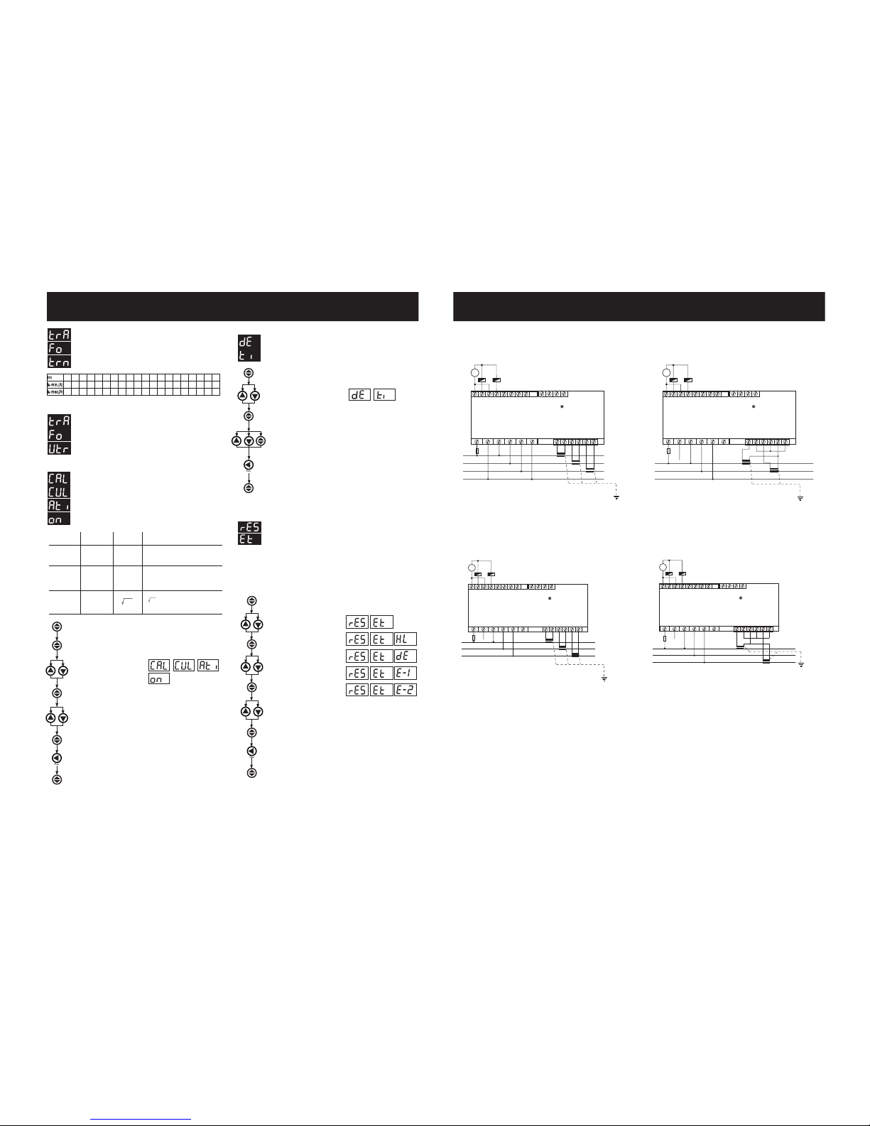
Demand Time Setup:
In this menu,demand time is set bet ween 1-60 minutes.
Press ESC button one by one until (SAU E SEt yES) is displayed.
Press SET button. When SAU E SEt yES is displayed, if you
press ESC button or choose no option instead of yES option
by using UP-DOWN buttons, new data will be cancelled and
previous value will be activated.
Press SET button for 3 seconds (trA Fo menu is displayed)
Press SET button (trA Fo Ctr menu is displayed)
Press SET button. (Most right digit of 5th display blinks)
Press set button, CAL CUL Atý on is displayed. (Data is entered
but is not activated yet. For activating the new data please follow
the below steps.)
Press ESC button one by one until SAU E SEt yES is displayed.
Press SET button. When SAU E SEt yES is displayed, if you
press ESC button or choose no option instead of yES option
by using UP-DOWN buttons, new data will be cancelled and
previous value will be activated.
By using UP-DOWN buttons, find
CAL CUL Atý on menu.
By using UP-DOWN buttons, select energy calculation method.
Reactive Energy Calculation Method Setting
0
2
4
1
3
5
Description
It is the most preferred reactive power calculation
methode.
Total value of the multiplication of V
n
and In values up
to 19 th harmonics. This calculation methode is mostly
preferred for network analysers.
S
Vn.In.sin(jn)
n=1
¥
Reactive Energy
(Q)
Digital Energymeter
(Each phase seperately)
Mechanical Energymeter
(Vectoral summation of 3-phase)
90° rotation of
voltage vector and
multiply with current
S2-P
2
S2-P
2
Power Triangle Methode : According to this methode;
Q =
(Q : Reactive power, S : Active power, P : Apparent power)
Press SET button for 3 seconds (trA Fo menu is displayed)
By using UP-DOWN buttons,
find rES Et menu.
Press SET button.
(rESEt HL menu is displayed)
By using UP-DOWN buttons, select
which parameter you want to reset.
Press SET button. (
rES Et dE / rES Et HL / rES Et E-1 / rES Et E-
2
is displayed.
Data is entered but is not activated yet. For
activating the new data please follow the below steps.
)
Press ESC button one by one until (SAU E SEt yES) is
displayed.
Press SET button, one of the
parameter
rES Et dE / rES Et HL /
rES Et E-1 / rES Et E-2 is displayed.
Press SET button. When SAU E SEt yES is displayed, if you
press ESC button or choose no option instead of yES option
by using UP-DOWN buttons, new data will be cancelled and
previous value will be activated.
By using UP-DOWN buttons, if you want to delete the min., max.,
max. demand or energy; select yES otherwise select no option.
For erasing the values of min. and max. or energy counter,
In the measurement mode :
Monitoring and Erasing of minimum, maximum and
energy values:
In this menu, values of min.,max. or energy counters are erased.
It saves the instantaneously measured min. and max. values of
MPR-53/53S into its memory. Please kindly look at to the section
of FUNCTIONS OF BUTTONS for min. and max. values.
Note : Measured electrical parameters which are saved to the
memory are not affected from the electric interruptions.
In the rESEt menu; when you quit from all menus, if you confirm
the changes,min. and max. values of all parameters or energy
counter values are erased at the same time.
Enter the blinking digit value by scrolling UP/DOWN buttons.
Switch to the other digits by using SET button, use BACK button
to go to previous digit. After you entered the last digit press SET
button, dE tý is displayed.
(Data is entered but is not activated
yet. For activating the new data please follow the below steps).
NETWORK ANALYSER
MPR-53/53S
7
Three different methods exist for reactive energy calculation in
MPR-53/53S. Brief informations about these methods are explained
in below table.
Related values which must be entered in the menu are also
indicated in the table in order to select reactive power calculation
method for mechanical and digital energymeters.
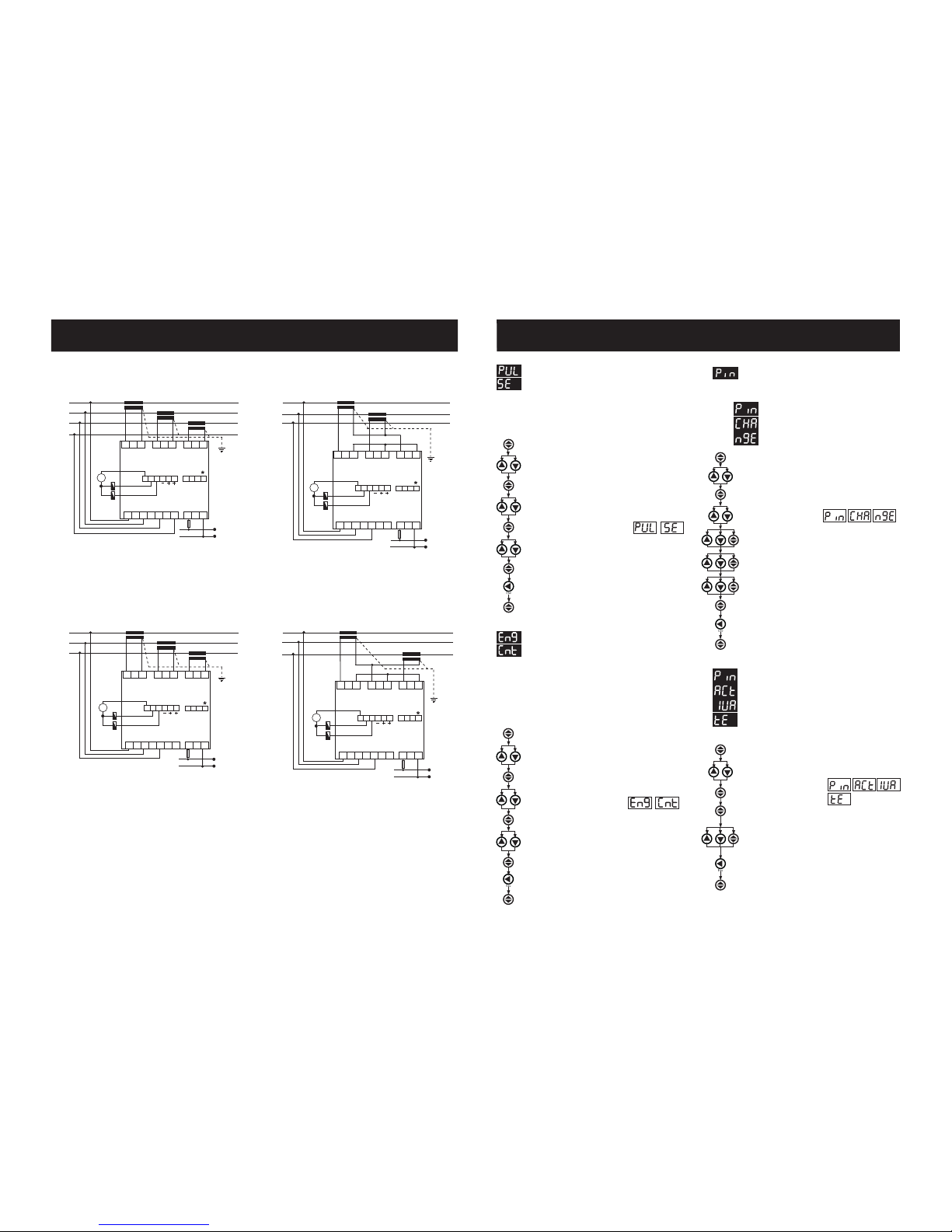
PK 26 Box Connection Diagram
*Available only for MPR-53S
~
U
n
TR A BGnd
IN2H
IN2L
IN1H
IN1L
PUL2H
PUL2L
PUL1H
PUL1L
I
L3
IL2I
L1
+
_
L3
L2
L1
1A
-+-+
(12-48V DC)
k
l
KL
k
l
KL
k
l
KL
~
U
n
TR A BGnd
IN2H
IN2L
IN1H
IN1L
PUL2H
PUL2L
PUL1H
PUL1L
I
L3
IL2I
L1
+
_
Max: 30 VDC
L3
L2
L1
-+-+
(12-48V DC)
1A
k
l
KL
k
l
KL
~
U
n
TR A BGnd
IN2H
IN2L
IN1H
IN1L
PUL2H
PUL2L
PUL1H
PUL1L
I
L3
IL2I
L1
+
_
Max: 30 VDC
L3
L2
L1
1A
-+-+
(12-48V DC)
k
l
KL
k
l
KL
~
U
n
TR A BGnd
IN2H
IN2L
IN1H
IN1L
PUL2H
PUL2L
PUL1H
PUL1L
I
L3
IL2I
L1
+
_
Max: 30 VDC
N
L3
L2
L1
1A
-+-+
(12-48V DC)
k
l
KL
k
l
KL
k
l
KL
Auxiliary
Supply
Voltage Measuring Input
Current Measuring Input
3 Phase neutral
L1
L2
L3
N
RS-485
Note: For CT-25 models:
1
2.00
120
2
1.00
60.0
3
0.66
40.0
4
0.50
30.0
5
0.40
24.0
6
0.33
20.0
7
0.28
17.1
8
0.24
15.0
9
0.22
13.3
10
0.20
12.0
11
0.18
10.9
12
0.16
10.0
13
0.15
9.23
14
0.14
8.57
15
0.13
8.00
16
0.12
7.50
17
0.11
7.05
18
0.11
6.66
19
0.10
6.31
20
0.10
6.00
Auxiliary
Supply
Voltage Measuring Input
Current Measuring Input
3 Phase without neutral current input with
Aron wiring configuration
L1
L2
L3
N
RS-485
N
Auxiliary
Supply
Voltage Measuring Input
Current Measuring Input
3 Phase without neutral
L1
L2
L3
N
RS-485
N
Max: 30 VDC
Auxiliary
Supply
Voltage Measuring Input
Current Measuring Input
3 Phase without neutral current input with
Aron wiring configuration
L1
L2
L3
N
RS-485
N
k: When CT-25 is used, Red cable is connected to k terminal.
l: When CT-25 is used, Black cable is connected to l terminal.
Page 3
NETWORK ANALYSER
MPR-53/53S
6
NETWORK ANALYSER
MPR-53/53S
3
Press ESC button one by one until (SAU E SEt yES) is displayed.
Press SET button. When SAU E SEt yES is displayed, if you
press ESC button or choose no option instead of yES option
by using UP-DOWN buttons, new data will be cancelled and
previous value will be activated.
Press SET button for 3 seconds (trA Fo menu is displayed)
By using UP-DOWN buttons, find Pýn menu.
Press SET button (Pýn ACt IUA tE
menu is displayed.)
Press SET button (First digit blinks)
Enter the values for blinking digits by using UP-DOWN buttons,
switch to other digits by using SET button use BACK button
to switch to previous digit Pýn ACt oF is displayed. on can
be selected by using UP / DOWN buttons. (Data is entered
but is not activated yet. For activating the new data please follow
below steps)
Activating the user password:
This menu is used for activating the user password.
After the user password is activated, while the instant values
are observed,user password is required in order to enter to
the menu. If the wrong user password is entered, user can
not enter to the menu.
Note: Factory default value of user password is 0000
Press SET button.
(Data is entered but is not activated yet.
For activating the new data please follow the below steps)
Press ESC button one by one until SAU E SEt yES is
displayed.
Press SET button. When SAU E SEt yES is displayed, if you
press ESC button or choose no option instead of yES option
by using UP-DOWN buttons, new data will be cancelled and
previous value will be activated.
Press SET button for 3 seconds (trA Fo menu is displayed)
By using UP-DOWN buttons, select
Eng Cnt E-1 / Eng Cnt E-2.
Press SET button. (on blinks)
By using UP-DOWN buttons, select required parameter.
By using UP-DOWN buttons, find Eng Cnt menu.
Press SET button (Eng Cnt E-1 menu is displayed)
For activating the user password, In the monitoring mode :
Energy Counter (Eng Cnt) Menu
MPR-53/53S has 2 energy counters :
Energy counter 1 (E-1), Energy counter 2 (E-2).
E-1 / E-2 have 4 parameters :
on : Activate E-1 / E-2 counters for energy counting without depending
on any parameter.
ý-1 : Activate E-1 / E-2 counters, when digital input 1 is on (=1).
ý-2 : Activate E-1 / E-2 counters, when digital input 2 is on (=1).
E-2: E-1 does not count when E-2 is activated. (Only for E-1)
E-1: E-2 does not count when E-1 is activated. (Only for E-2)
Note: Counting status is undefned if E-2 is selected on E-1 and if E-1 is selected on
E-2. When the status is defined as above, both energy counters count while digital
input is not on (=1), but if either one or both digital inputs are on (=1) then counters
will not count.
By using UP-DOWN-SET buttons, enter the new password
By using UP-DOWN-SET buttons, re-enter the new password.
By using UP-DOWN-SET buttons, enter the old password
In this menu user password is defined and activated.
You must define and activate a 4 digit user password for
preventing device settings from the illegal usage.
There are 2 sub menus under the Pýn menu.
This menu is used to change the user password .
Note: Factory default value for user password is
0000
To change the user password,
In the monitoring mode :
Press SET button for 3 seconds (trA Fo menu is displayed)
Bu using UP-DOWN buttons, find Pýn menu.
Press SET button (Pýn ACt IUA tE menu is displayed)
By using the UP-DOWN buttons,
find Pýn CHA ngE menu.
User password Setup:
Changing of User Password:
Press SET button, Pýn CHA ngE is displayed. (Data is entered
but is not activated yet. For activating the new data please
follow the below steps).
Press ESC button one by one until (SAU E SEt yES) is
displayed.
Press SET button. When SAU E SEt yES is displayed, if you
press ESC button or choose no option instead of yES option
by using UP-DOWN buttons, new data will be cancelled and
previous value will be activated.
Pulse Menu
Press SET button for 3 seconds (trA Fo menu is displayed)
By using UP-DOWN buttons, select PUL SE rAt ýo,
PUL SE o-1 or PUL SE o-2.
By using UP-DOWN buttons, select required parameter.
By using UP-DOWN buttons, find PULSE menu.
Press SET button (PUL SE rAt ýo menu is displayed)
Press SET button.
(Data is entered but is not activated yet.
For activating the new data please follow the below steps)
Press ESC button one by one until SAU E SEt yES is
displayed.
Press SET button. When SAU E SEt yES is displayed, if you
press ESC button or choose no option instead of yES option
by using UP-DOWN buttons, new data will be cancelled and
previous value will be activated.
In this menu, three parameters can be selected :
PUL SE rAt ýo, PUL SE o-1, PUL SE o-2
PUL SE rAt : Pulse menu which is defined for how many pulses
deticated for energy consumption. PUL SE rAt value can be
assigned as below:
Press SET button (1k / A-I / r-L blink)
1, 10, 100 (wh/VArh/VA); 1, 10, 100 (kwh/kVArh/kVA); 1 Mwh/MVArh/MVA.
PUL SE o-1 / PUL SE o-2: 1 Pulse is taken for respected energy
consumption which assigned in PUL SE rAt. o-1 / o-2 can be assigned
as below :
ACt (Export/Import), A-I (Active Import), A-E (Active Export), rEA (Inductive
/ Capacitive), r-L (Reactive Inductive), r-C (Reactive Capacitive).
+
_
N
L1
L2
L3
1 A
L1
N
Current Measuring Input
Auxiliary
Supply
L1
L2
L3
N
12345
6
Voltage Measuring Input
k
l
KL
k
l
KL
k
l
KL
IL1
IL2
IL3
RS485
GND A TR
Max: 30 VDC
Pul 1 Pul 2
Pul C InC In1 In2
B
( 12-48V DC )
13 14 15 16 17 18 19 20 21 22
78910
11 12
3 Phase neutral
+
_
+
_
L1
L2
L3
1 A
L1
N
Current Measuring Input
Auxiliary
Supply
L1
L2
L3
N
12345
6
Voltage Measuring Input
k
l
KL
k
l
KL
IL1
IL2
IL3
RS485
GND A TR
Max: 30 VDC
Pul 1 Pul 2
Pul C InC In1 In2
B
( 12-48V DC )
13 14 15 16 17 18 19 20 21 22
78910
11 12
3 Phase without neutral current input with
Aron wiring configuration
+
_
L1
L2
L3
k
l
KL
k
l
KL
1 A
L1
N
Current Measuring Input
Auxiliary
Supply
L1
L2
L3
N
12345
6
Voltage Measuring Input
IL1
IL2
IL3
RS485
GND A TR
Max: 30 VDC
Pul 1 Pul 2
Pul C InC In1 In2
B
( 12-48V DC )
13 14 15 16 17 18 19 20 21 22
78910
11 12
3 Phase without neutral current input with
Aron wiring configuration
*Available only for MPR-53S
Note: For CT-25 models:
PR 19 Box Connection Diagram
3 Phase without neutral
L1
L2
L3
1 A
L1
N
k
l
KL
k
l
KL
k
l
KL
Current Measuring Input
Auxiliary
Supply
L1
L2
L3
N
12345
6
Voltage Measuring Input
IL1
IL2
IL3
RS485
GND A TR
Max: 30 VDC
Pul 1 Pul 2
Pul C InC In1 In2
B
( 12-48V DC )
13 14 15 16 17 18 19 20 21 22
78910
11 12
k: When CT-25 is used, Red cable is connected to k terminal.
l: When CT-25 is used, Black cable is connected to l terminal.
Page 4
NETWORK ANALYSER
MPR-53/53S
4
Preset Multiple Register(10H) is used to set more then one register at same
time.
i.e. Setting CT as 100, Ut as 20.0;
01 10 80 00 00 02 04 00 C8 00 64 XX XX
01 Device Address
10 Function
80 MSB address
00 LSB address
00 Register number MSB
02 Register number LSB
04 Byte count
00 Data MSB
C8 Data LSB
00 Data MSB
64 Data LSB
XX CRC MSB
XX CRC LSB
Preset Single Register (06) function is used for writting the setting values,
erasing the energy counter or resetting the min., max., demand values.
Current transformers ratio can be set 0-2000, voltage transformer ratio can
be set 1-40000. Min., Max. and Demand values can be only clear. If sent
value is outside of this range device responds with an error message.
i.e. Setting CT as 100;
01 06 80 02 00 64 XX XX
01 Device address
06 Function
80 MSB address
02 LSB address
00 Data MSB
64 Data LSB
XX CRC MSB
XX CRC LSB
Read Hold (03) function is used for reading measured values and set value.
If any request of reading of a register, excepted mentioned in register table,
device will send an error message. For example to read phase1 voltage by
sending a message to the device.
01 03 00 00 00 02 XX XX
01 Device address
03 Function
00 MSB address
00 LSB address
00 Register number MSB
02 Register number LSB
XX CRC MSB
XX CRC LSB
Available Modbus Function:
The T times corresponds to a time in which data must not be exchanged
on the communication bus to allow the connected devices to recognize the
end of one message and the beginning of another. This time must be at
least 3.5 characters at the selected baud rate. Adress range (1-247 ) is
address of the connected device. The data field contains data sent to the
slave by master or data sent to master by slave.
CRC is a error check method by using MODBUS RTU protocol and consists
of 2 bytes.
MODBUS RTU PROTOCOL
(Available only for MPR-53S)
Standart MODBUS RTU message is shown below.
NETWORK ANALYSER
MPR-53/53S
5
Serial Communication (Available only for MPR-53S)
Parameter Settings
(Available only for MPR-53S)
Address : 001-247
Baud Rate : 2400, 4800, 9600, 19200, 34800 bps
Parity : no, odd and EUEn
Press SET button, Adr ESS / bAU d / PArýty displayed.
(Data is
entered but is not activated yet. For activating the new data please
follow the below steps)
Press ESC button one by one until SAU E SEt yES is
displayed.
Press SET button. When SAU E SEt yES is displayed, if you
press ESC button or choose no option instead of yES option
by using UP-DOWN buttons, new data will be cancelled and
previous value will be activated.
Press SET button for 3 seconds (trA Fo menu is displayed)
By using UP-DOWN buttons, select Adr ESS / bAU d /
PArýty
Press SET button. (001 / 9600 / no displayed)
By using UP-DOWN buttons, select required parameter
(001...247 / 2400...38400 / no, EUEn, odd).
By using UP-DOWN buttons,
find rS-485 menu.
Press SET button (Adr ESS menu is displayed)
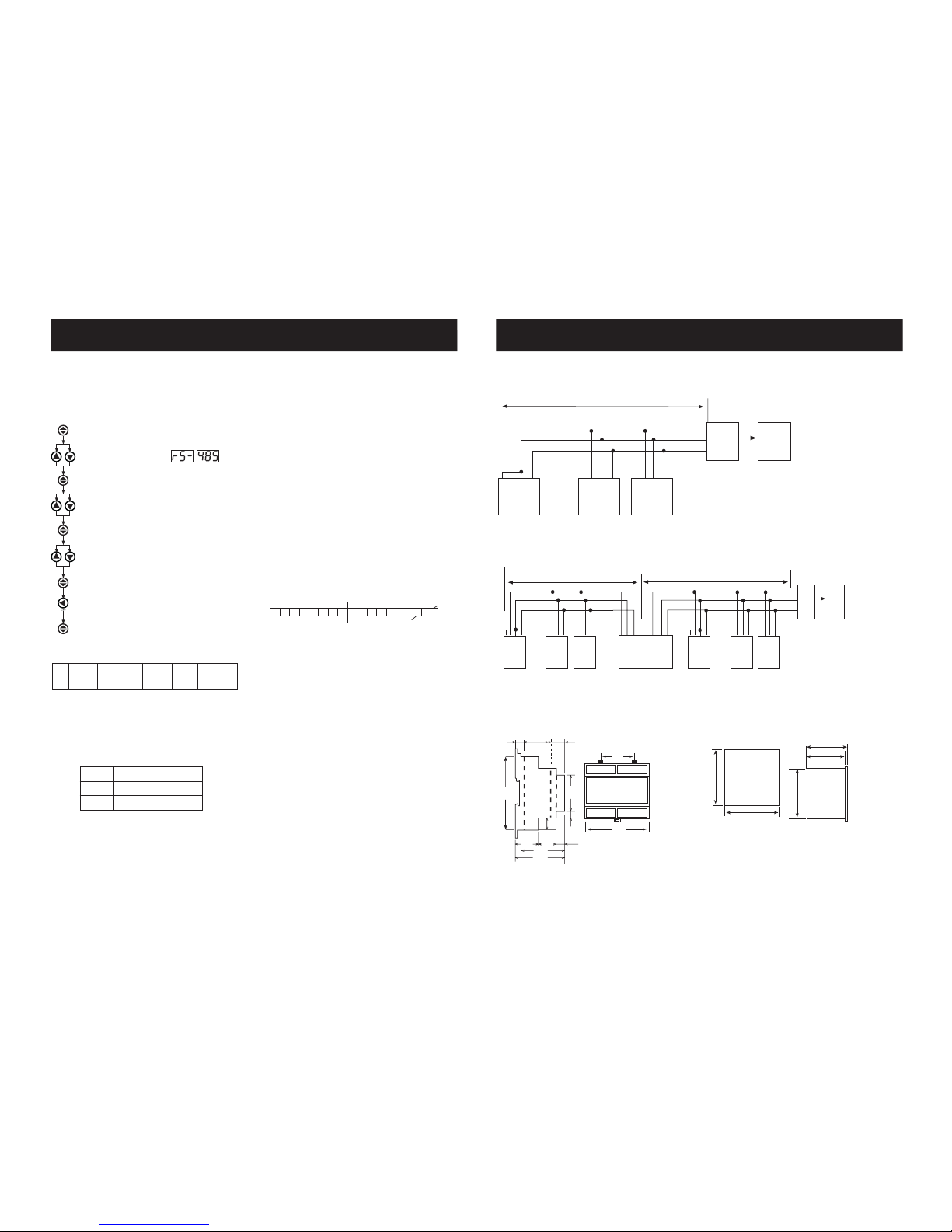
MPR-53S has MODBUS RTU communication protocol which is optical
isolated. All measured parameters can be transfer to the computer.
Transformer ratios and communication parameters can be set, saved
parameters for demand and energy values can be reset.
T
ADDRESS
8 BIT
FUNCTION
8 BIT
DATA
NX8BIT
CRCH CRCL T
03H READ HOLD REGISTERS
06H PRESET SINGLE REGISTER
10H PRESET MULTIPLE REGISTERS
ERROR CODES
(Available only for MPR-53S)
Slave device (MPR-53S) sends error message when receive any missing query.
Error codes are given below.
01 Invalid Function: If any message except given above is used, then 01 error
messages will be sent.
02 Invalid Register: Error 02 will be send when a reading of a register is
requested, except the registers which mentioned in table.
03 Invalid data: If any different value is been set for dedicated Transformer
values and nonzero for demand value, then error message 03 will be sent.
The Parameters are sent in 32bit Hexadecimal format. For Example, 230.0V
voltage will be sent as 000008FCH. Cosj values shall be divided to 1000.
0.980 Cosj will be sent as 000003D4H. Energy values are sent in 64 bytes.
1234567890123456789 Wh = AB 54 A9 8C EB 1F 0A 02 Wh
Specifications for data cable ;
- 24 AWG or thicker
- Less than 100 ohm/ km
- Nominal characteristic impedance at 100 kHz of 100 ohms
- Less than 60 pF/m mutual capacitance (between two wires in a pair)
- Less than 120 pF/m mutual pair capacitance ( the capacitance between one
wire and all others connected to earth).
- Twisted Pair
Digital input are sent in 16 bit hexadecimal format as below:
If 12-48 V AC / DC is applied to ln1 (Input 1), 0 (zero) bit of DIN register
is set as 1. Otherwise, 0 (zero) bit is set as 0.
If 12-48 V AC / DC is applied to ln2 (Input 2), 1st bit of DIN register is
set as 1. Otherwise, 1st bit is set as 0.
Digital Inputs
(Available only for MPR-53S)
55H
15
UUUUUUUU UUUUUU
input 2
input 1
DIN1
DIN2
0
U: undefined
LSB
(Least Significant Byte)
MSB
(Most Significant Byte)
1
MPR-53S COMPUTER CONNECTION
31 DEVICES CAN BE CONNECTED AT THE SAME LINE
GNDTR B A
GNDTR B A
GNDTR B A
GND
B
A
RS485/RS232
CONVERTER
PC
..
.
MPR-53S-1MPR-53S-2MPR-53S-31
MAX. 1200 mt.
MAX. 247 DEVICES CAN BE CONNECTED AT SAME LINE BY USING REPEATER.
GND
TR
B
A
..
.
MPR-53S
-247
GND
B
A
RS485/RS232
CONVERTER
PC
..
.
MPR-53S
-1
MPR-53S
-2
MPR-53S
-31REPEATER
MAX. 1200 mt.
MAX. 1200 mt.
Dimensions
70mm
79.3mm
90mm
96mm
96mm
60.6
106.0
10.8
30.1 7.6 9.5
26.5 21.5
53.0
58.0
10.0
8.5
14.0
45.0
90.0
Type PK 26
Type PR 19
Page 5
NETWORK ANALYSER
MPR-53/53S
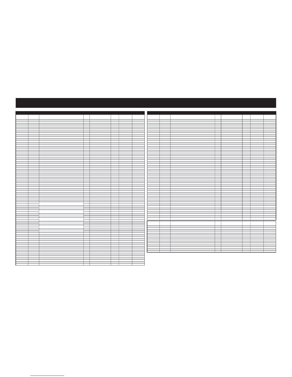
MODBUS REGISTER MAP
ADDRESS
ADDRESS
(HEX)
REGISTER RANGE UNIT FORMAT
Volt
Volt
Volt
Amper
Amper
Amper
Amper
Volt
Volt
Volt
Watt
Watt
Watt
Var
Var
Var
VA
VA
VA
-
-
Watt
Watt
Var
Var
VA
-
-
Hz
Degre
Degre
Degre
Degre
Degre
Degre
%
%
%
%
%
%
Wh
Wh
Wh
Wh
VArh
VArh
VArh
VArh
Wh
Wh
Wh
Wh
VArh
VArh
VArh
VArh
Volt
Volt
Volt
Volt
Volt
Volt
Amper
Amper
Amper
Watt
Watt
Watt
Var
Var
Var
VA
VA
0000
0002
0004
0006
0008
000A
000C
000E
0010
0012
0014
0016
0018
001A
001C
001E
0020
0022
0024
0026
0028
002A
002C
002E
0030
0032
0034
0036
0038
003A
003C
003E
0040
0042
0044
0046
0048
004A
004C
004E
0050
0052
0054
0056
0058
005A
005C
005E
0060
0062
0064
0066
0068
006A
006C
006E
0070
0072
0074
0076
0078
007A
007C
007E
0080
0082
0084
0086
0088
008A
008C
008E
0090
0092
0094
0096
0
2
4
6
8
10
12
14
16
18
20
22
24
26
28
30
32
34
36
38
40
42
44
46
48
50
52
54
56
58
60
62
64
66
68
70
72
74
76
78
80
82
84
86
88
90
92
94
96
98
100
102
104
106
108
110
112
114
116
118
120
122
124
126
128
130
132
134
136
138
140
142
144
146
148
150
R/W
R
R
R
R
R
R
R
R
R
R
R
R
R
R
R
R
R
R
R
R
R
R
R
R
R
R
R
R
R
R
R
R
R
R
R
R
R
R
R
R
R
R
R
R/W
R/W
R/W
R/W
R/W
R/W
R/W
R/W
R/W
R/W
R/W
R/W
R/W
R/W
R/W
R/W
R/W
R/W
R/W
R/W
R/W
R/W
R/W
R/W
R/W
R/W
R/W
R/W
R/W
R/W
R/W
R/W
R/W
MULTIPLIER
(0-3000)xUT
(0-3000)xUT
(0-3000)xUT
(0-6000)xCT
(0-6000)xCT
(0-6000)xCT
(0-6000)xCT
(0-5000)xUT
(0-5000)xUT
(0-5000)xUT
(-18000 - 18000)xCTxVT
(-18000 - 18000)xCTxVT
(-18000 - 18000)xCTxVT
(-18000 - 18000)xCTxVT
(-18000 - 18000)xCTxVT
(-18000 - 18000)xCTxVT
(0 -18000)xCTxVT
(0 -18000)xCTxVT
(0 -18000)xCTxVT
(-1000 -1000)
(-1000 -1000)
(-1000 -1000)
(0 -54000)xCTxVT
(0 -54000)xCTxVT
(0 -54000)xCTxVT
(0 -54000)xCTxVT
(0 -54000)xCTxVT
(-1000 -1000)
(-1000 -1000)
(4000 -7000)
0-360
0-360
0-360
0-360
0-360
0-360
0-999
0-999
0-999
0-999
0-999
0-999
0-FFFFFFFFFFFFFFFF
0-FFFFFFFFFFFFFFFF
0-FFFFFFFFFFFFFFFF
0-FFFFFFFFFFFFFFFF
0-FFFFFFFFFFFFFFFF
0-FFFFFFFFFFFFFFFF
0-FFFFFFFFFFFFFFFF
0-FFFFFFFFFFFFFFFF
0-FFFFFFFFFFFFFFFF
0-FFFFFFFFFFFFFFFF
0-FFFFFFFFFFFFFFFF
0-FFFFFFFFFFFFFFFF
0-FFFFFFFFFFFFFFFF
0-FFFFFFFFFFFFFFFF
0-FFFFFFFFFFFFFFFF
0-FFFFFFFFFFFFFFFF
(0-3000)xUT
(0-3000)xUT
(0-3000)xUT
(0-3000)xUT
(0-3000)xUT
(0-3000)xUT
(0-6000)xCT
(0-6000)xCT
(0-6000)xCT
(-18000 - 18000)xCTxVT
(-18000 - 18000)xCTxVT
(-18000 - 18000)xCTxVT
(-18000 - 18000)xCTxVT
(-18000 - 18000)xCTxVT
(-18000 - 18000)xCTxVT
(0 - 18000)xCTxVT
(0 - 18000)xCTxVT
0.1
0.1
0.1
0.001
0.001
0.001
0.001
0.1
0.1
0.1
0.1
0.1
0.1
0.1
0.1
0.1
0.1
0.1
0.1
0.001
0.001
0.001
0.1
0.1
0.1
0.1
0.1
0.001
0.001
0.01
1
1
1
1
1
1
0.1
0.1
0.1
0.1
0.1
0.1
1
1
1
1
1
1
1
1
1
1
1
1
1
1
1
1
0.1
0.1
0.1
0.1
0.1
0.1
0.001
0.001
0.001
0.1
0.1
0.1
0.1
0.1
0.1
0.1
0.1
unsigned int
unsigned int
unsigned int
unsigned int
unsigned int
unsigned int
unsigned int
unsigned int
unsigned int
unsigned int
int
int
int
int
int
int
unsigned int
unsigned int
unsigned int
int
int
int
int
int
int
int
unsigned int
int
int
unsigned int
unsigned int
unsigned int
unsigned int
unsigned int
unsigned int
unsigned int
unsigned int
unsigned int
unsigned int
unsigned int
unsigned int
unsigned int
long int
long int
long int
long int
long int
long int
long int
long int
long int
long int
long int
long int
long int
long int
long int
long int
unsigned int
unsigned int
unsigned int
unsigned int
unsigned int
unsigned int
unsigned int
unsigned int
unsigned int
int
int
int
int
int
int
unsigned int
unsigned int
MODBUS REGISTER MAP
ADDRESS
ADDRESS
(HEX)
REGISTER RANGE UNIT FORMAT
VA
Watt
Watt
Var
Var
VA
Volt
Volt
Volt
Volt
Volt
Volt
Amper
Amper
Amper
Watt
Watt
Watt
Var
Var
Var
VA
VA
VA
Watt
Watt
Var
Var
VA
Amper
Amper
Amper
Watt
Watt
Watt
Watt
Watt
Watt
Var
Var
Var
Var
Var
Var
VA
VA
VA
Watt
Watt
Var
Var
VA
0098
009A
009C
009E
00A0
00A2
00A4
00A6
00A8
00AA
00AC
00AE
00B0
00B2
00B4
00B6
00B8
00BA
00BC
00BE
00C0
00C2
00C4
00C6
00C8
00CA
00CC
00CE
00D0
00D2
00D4
00D6
00D8
00DA
00DC
00DE
00E0
00E2
00E4
00E6
00E8
00EA
00EC
00EE
00F0
00F2
00F4
00F6
00F8
00FA
00FC
00FE
152
154
156
158
160
162
164
166
168
170
172
174
176
178
180
182
184
186
188
190
192
194
196
198
200
202
204
206
208
210
212
214
216
218
220
222
224
226
228
230
232
234
236
238
240
242
244
246
248
250
252
254
R/W
R/W
R/W
R/W
R/W
R/W
R/W
R/W
R/W
R/W
R/W
R/W
R/W
R/W
R/W
R/W
R/W
R/W
R/W
R/W
R/W
R/W
R/W
R/W
R/W
R/W
R/W
R/W
R/W
R/W
R/W
R/W
R/W
R/W
R/W
R/W
R/W
R/W
R/W
R/W
R/W
R/W
R/W
R/W
R/W
R/W
R/W
R/W
R/W
R/W
R/W
R/W
R/W
L3 PHASE MIN. APPARENT POWER
TOTAL MIN. IMPORT ACTIVE POWER
TOTAL MIN. EXPORT ACTIVE POWER
TOTAL MIN. IMPORT REACTIVE POWER
TOTAL MIN. EXPORT REACTIVE POWER
TOTAL MIN. APPARENT POWER
L1 PHASE MAX. VOLTAGE
L2 PHASE MAX. VOLTAGE
L3 PHASE MAX. VOLTAGE
L1-L2 PHASE-PHASE MAX. VOLTAGE
L2-L3 PHASE-PHASE MAX. VOLTAGE
L3-L1 PHASE-PHASE MAX. VOLTAGE
L1 PHASE MAX. CURRENT
L2 PHASE MAX. CURRENT
L3 PHASE MAX. CURRENT
L1 PHASE MAX. ACTIVE POWER
L2 PHASE MAX. ACTIVE POWER
L3 PHASE MAX. ACTIVE POWER
L1 PHASE MAX. REACTIVE POWER
L2 PHASE MAX. REACTIVE POWER
L3 PHASE MAX. REACTIVE POWER
L1 PHASE MAX. APPARENT POWER
L2 PHASE MAX. APPARENT POWER
L3 PHASE MAX. APPARENT POWER
TOTAL MAX. IMPORT ACTIVE POWER
TOTAL MAX. EXPORT ACTIVE POWER
TOTAL MAX. IMPORT REACTIVE POWER
TOTAL MAX. EXPORT REACTIVE POWER
TOTAL MAX. APPARENT POWER
L1 PHASE MAX. CURRENT DEMAND
L2 PHASE MAX. CURRENT DEMAND
L3 PHASE MAX. CURRENT DEMAND
L1 PHASE IMPORT MAX. DEMAND ACTIVE POWER
L1 PHASE EXPORT MAX. DEMAND ACTIVE POWER
L2 PHASE IMPORT MAX. DEMAND ACTIVE POWER
L2 PHASE EXPORT MAX. DEMAND ACTIVE POWER
L3 PHASE IMPORT MAX. DEMAND ACTIVE POWER
L3 PHASE EXPORT MAX. DEMAND ACTIVE POWER
L1 PHASE IMPORT MAX. DEMAND REACTIVE POWER
L1 PHASE EXPORT MAX. DEMAND REACTIVE POWER
L2 PHASE IMPORT MAX. DEMAND REACTIVE POWER
L2 PHASE EXPORT MAX. DEMAND REACTIVE POWER
L3 PHASE IMPORT MAX. DEMAND REACTIVE POWER
L3 PHASE EXPORT MAX. DEMAND REACTIVE POWER
L1 PHASE MAX. DEMAND APPARENT POWER
L2 PHASE MAX. DEMAND APPARENT POWER
L3 PHASE MAX. DEMAND APPARENT POWER
TOTAL IMPORT MAX. DEMAND ACTIVE POWER
TOTAL EXPORT MAX. DEMAND ACTIVE POWER
TOTAL IMPORT MAX. DEMAND REACTIVE POWER
TOTAL EXPORT MAX. DEMAND REACTIVE POWER
TOTAL MAX. DEMAND APPARENT POWER
MULTIPLIER
(0 - 18000)xCTxVT
(-18000 - 18000)xCTxVT
(-18000 - 18000)xCTxVT
(-18000 - 18000)xCTxVT
(-18000 - 18000)xCTxVT
(0 - 18000)xCTxVT
(0-3000)xUT
(0-3000)xUT
(0-3000)xUT
(0-5000)xUT
(0-5000)xUT
(0-5000)xUT
(0-6000)xCT
(0-6000)xCT
(0-6000)xCT
(-18000 - 18000)xCTxVT
(-18000 - 18000)xCTxVT
(-18000 - 18000)xCTxVT
(-18000 - 18000)xCTxVT
(-18000 - 18000)xCTxVT
(-18000 - 18000)xCTxVT
(0 - 18000)xCTxVT
(0 - 18000)xCTxVT
(0 - 18000)xCTxVT
(-18000 - 18000)xCTxVT
(-18000 - 18000)xCTxVT
(-18000 - 18000)xCTxVT
(-18000 - 18000)xCTxVT
(0 - 18000)xCTxVT
(0-6000)xCT
(0-6000)xCT
(0-6000)xCT
(-18000 - 18000)xCTxVT
(-18000 - 18000)xCTxVT
(-18000 - 18000)xCTxVT
(-18000 - 18000)xCTxVT
(-18000 - 18000)xCTxVT
(-18000 - 18000)xCTxVT
(-18000 - 18000)xCTxVT
(-18000 - 18000)xCTxVT
(-18000 - 18000)xCTxVT
(-18000 - 18000)xCTxVT
(-18000 - 18000)xCTxVT
(-18000 - 18000)xCTxVT
(0 - 18000)xCTxVT
(0 - 18000)xCTxVT
(0 - 18000)xCTxVT
(-18000 - 18000)xCTxVT
(-18000 - 18000)xCTxVT
(-18000 - 18000)xCTxVT
(-18000 - 18000)xCTxVT
(0 - 18000)xCTxVT
0.1
0.1
0.1
0.1
0.1
0.1
0.1
0.1
0.1
0.1
0.1
0.1
0.001
0.001
0.001
0.1
0.1
0.1
0.1
0.1
0.1
0.1
0.1
0.1
0.1
0.1
0.1
0.1
0.1
0.001
0.001
0.001
0.1
0.1
0.1
0.1
0.1
0.1
0.1
0.1
0.1
0.1
0.1
0.1
0.1
0.1
0.1
0.1
0.1
0.1
0.1
0.1
unsigned int
int
int
int
int
unsigned int
unsigned int
unsigned int
unsigned int
unsigned int
unsigned int
unsigned int
unsigned int
unsigned int
unsigned int
int
int
int
int
int
int
unsigned int
unsigned int
unsigned int
int
int
int
int
unsigned int
unsigned int
unsigned int
unsigned int
int
int
int
int
int
int
int
int
int
int
int
int
unsigned int
unsigned int
unsigned int
int
int
int
int
unsigned int
ADDRESS
ADDRESS
(HEX)
REGISTER RANGE UNIT FORMAT
-
-
-
minute
-
-
-
-
-
-
-
-
-
-
8000
8001
8002
8003
8004
8005
8006
8007
8008
8009
800A
800B
800C
800D
32768
32769
32770
32771
32772
32773
32774
32775
32776
32777
32778
32779
32780
32781
R/W
R/W
R/W
R/W
R/W
R/W
R/W
R/W
R/W
R/W
R/W
R/W
R/W
R/W
R/W
VOLTAGE TRANSFORMER RATIO
CURRENT TRANSFORMER RATIO
CALCULATION METHOD
DEMAND TIME
PULSE RATIO
PULSE OUTPUT 1 PARAMETER SETTING
PULSE OUTPUT 2 PARAMETER SETTING
ENERGY COUNTER 1 SELECTION
ENERGY COUNTER 2 SELECTION
COMMUNICATION ADDRESS
BAUD RATE
PARITY
PASSWORD ENABLE
PASSWORD
MULTIPLIER
0-40000
0-2000
0-5
1-60
0-6
0-5
0-5
0-3
0-3
0 - 247
1 - 5
0 - 2
0-1
0-9999
0.1
1
1
-
-
-
-
-
-
-
-
-
-
short-int
short-int
short-int
short-int
short-int
short-int
short-int
short-int
short-int
short-int
short-int
short-int
short-int
short-int
*Available only for MPR-53S
PULSE OUTPUT 1-2
PARAMETER SETTING 0-5 :
0: Active
1: Active Import
2: Active Export
3: Reactive
4: Reactive Import
5: Reactive Export
ENERGY COUNTER 1 SELECTION 0-3 :
0 : On (EC -Energy counter- will count on all conditions)
1: EC will count when Digital Input1 is 1 (1=active)
2: EC will count when Digital Input2 is 1 (1=active)
3: Inverse Energy Counter 2 (It will count when EC2 is not counted)
ENERGY COUNTER 2 SELECTION 0-3 :
0 : On (EC -Energy counter- will count on all conditions)
1: EC will count when Digital Input1 is 1 (1=active)
2: EC will count when Digital Input2 is 1 (1=active)
3: Inverse Energy Counter 1 (It will count when EC1 is not counted)
BAUD RATE 1-5 :
1: 38400 bps
2: 19200 bps
3: 9600 bps
4: 4800 bps
5: 2400 bps
PARITY 0-2 :
0: No
1: Odd
2: Even
PASSWORD ENABLE 0-1 :
0: Disable
1: Enable
PULSE RATIO 0-6 :
0: 1 Watt / Pulse
1: 10 Watt / Pulse
2: 100 Watt / Pulse
3: 1 kW / Pulse
4: 10 kW / Pulse
5: 100 kW / Pulse
6: 1 MW / Pulse
CALCULATION 0-5 :
Refer to Reactive Energy Calculation Method Setting on page 2.
L1 PHASE VOLTAGE
L2 PHASE VOLTAGE
L3 PHASE VOLTAGE
L1 PHASE CURRENT
L2 PHASE CURRENT
L3 PHASE CURRENT
NEUTRAL CURRENT
L1-L2 PHASE-PHASE VOLTAGE
L2-L3 PHASE-PHASE VOLTAGE
L3-L1 PHASE-PHASE VOLTAGE
L1 PHASE ACTIVE POWER
L2 PHASE ACTIVE POWER
L3 PHASE ACTIVE POWER
L1 PHASE REACTIVE POWER
L2 PHASE REACTIVE POWER
L3 PHASE REACTIVE POWER
L1 PHASE APPARENT POWER
L2 PHASE APPARENT POWER
L3 PHASE APPARENT POWER
L1 PHASE COSj
L2 PHASE COSj
L3 PHASE COSj
TOTAL IMPORT ACTIVE POWER
TOTAL EXPORT ACTIVE POWER
TOTAL INDUCTIVE REACTIVE POWER
TOTAL CAPACITIVE REACTIVE POWER
TOTAL APPARENT POWER
AVERAGE INDUCTIVE COSj
AVERAGE CAPACITIVE COSj
FREQUENCY
L1 PHASE VOLTAGE ANGLE
L2 PHASE VOLTAGE ANGLE
L3 PHASE VOLTAGE ANGLE
L1 PHASE CURRENT ANGLE
L2 PHASE CURRENT ANGLE
L3 PHASE CURRENT ANGLE
L1 PHASE VOLTAGE THD
L2 PHASE VOLTAGE THD
L3 PHASE VOLTAGE THD
L1 PHASE CURRENT THD
L2 PHASE CURRENT THD
L3 PHASE CURRENT THD
DIGITAL INPUT STATUS
IMPORT ACTIVE ENERGY-1
EXPORT ACTIVE ENERGY-1
INDUCTIVE REACTIVE ENERGY-1
CAPACITIVE REACTIVE ENERGY-1
IMPORT ACTIVE ENERGY-2
EXPORT ACTIVE ENERGY-2
INDUCTIVE REACTIVE ENERGY-2
CAPACITIVE REACTIVE ENERGY-2
L1 PHASE MIN. VOLTAGE
L2 PHASE MIN. VOLTAGE
L3 PHASE MIN. VOLTAGE
L1-L2 PHASE-PHASE MIN. VOLTAGE
L2-L3 PHASE-PHASE MIN. VOLTAGE
L3-L1 PHASE-PHASE MIN. VOLTAGE
L1 PHASE MIN. CURRENT
L2 PHASE MIN. CURRENT
L3 PHASE MIN. CURRENT
L1 PHASE MIN. ACTIVE POWER
L2 PHASE MIN. ACTIVE POWER
L3 PHASE MIN. ACTIVE POWER
L1 PHASE MIN. REACTIVE POWER
L2 PHASE MIN. REACTIVE POWER
L3 PHASE MIN. REACTIVE POWER
L1 PHASE MIN. APPARENT POWER
L2 PHASE MIN. APPARENT POWER
MODBUS REGISTER MAP
A4309/Rev.1
 Loading...