


MPR-2 SERIES NETWORK ANALYZER
OPERATING MANUAL
Index
SAFETY AND WARNING ................................................................................................................................ 3
Attention .................................................................................................................................................. 3
Safety ....................................................................................................................................................... 4
Guarantee ................................................................................................................................................ 4
OPERATING CONDITIONS ............................................................................................................................. 5
INTRODUCTION ............................................................................................................................................ 6
General Specifications ............................................................................................................................. 6
Applications.............................................................................................................................................. 7
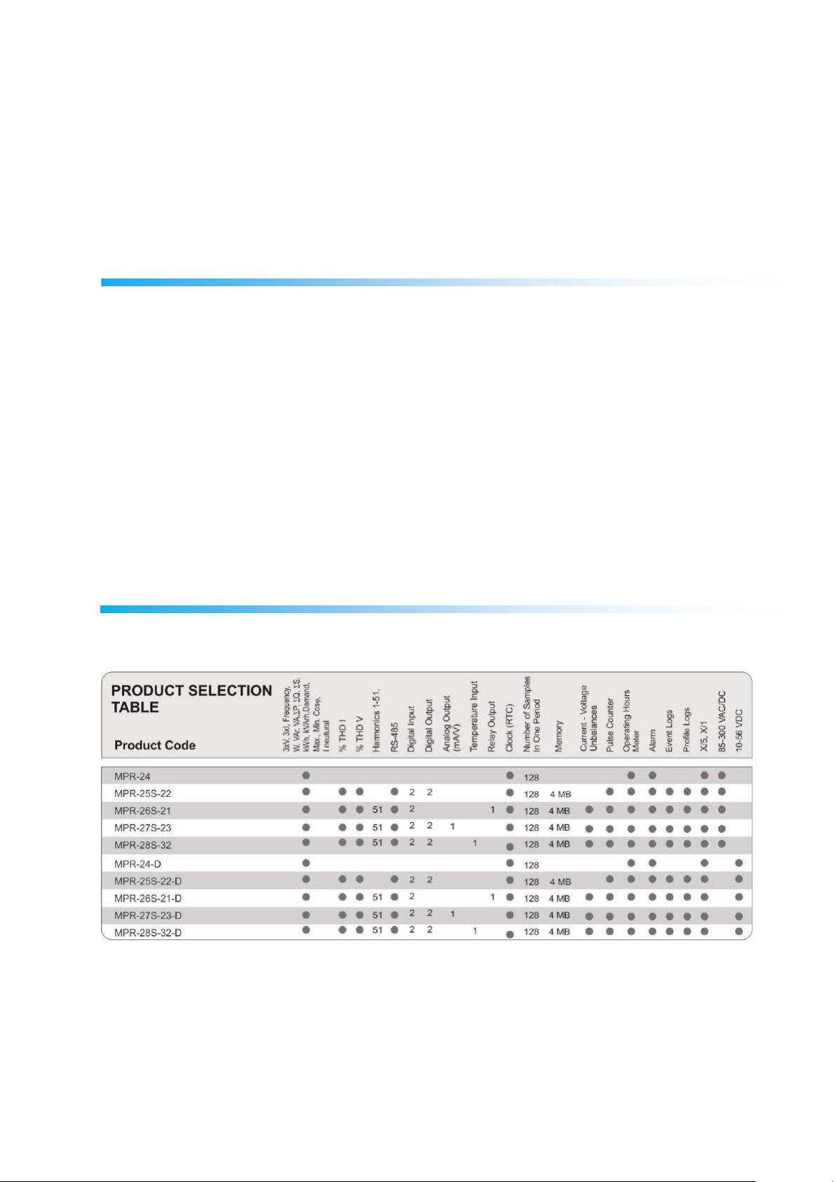
MPR-2 Product Family............................................................................................................................. 7
Appearance and Interface ....................................................................................................................... 8
Terminals .............................................................................................................................................. 8
Front Panel ........................................................................................................................................... 8
Button Functions ...................................................................................................................................... 9
Terminal Structures................................................................................................................................ 10
CONNECTION ............................................................................................................................................. 14
3P4W (Three-Phase Four-Wire) Connection ......................................................................................... 14
3P3W (Three-Phase Three-Wire) Connection ....................................................................................... 15
ARON Connection .................................................................................................................................. 15
3P4W BLN (Three-Phase Four-Wire Balanced) Connection .................................................................. 16
3P3W BLN (Three-Phase Three-Wire Balanced) Connection................................................................. 16
Connection Control ................................................................................................................................ 17
Communication Line Termination Resistance ....................................................................................... 18
OPERATING DEVICE .................................................................................................................................... 19
Instant Measurement Screens .............................................................................................................. 19
1

Current, Voltage and Frequency Screens .......................................................................................... 19
Power and Power Factor Screens ...................................................................................................... 21
Energy and Harmonic Screens .......................................................................................................... 23
Minimum, Maximum and Demand Screens ..................................................................................... 26
Settings Screen ....................................................................................................................................... 31
Installation Settings of the Device .................................................................................................... 31
Display Settings .................................................................................................................................. 35
Time Settings ...................................................................................................................................... 36
RS-485 Communication Settings ....................................................................................................... 38
Input Parameter Settings ................................................................................................................... 40
Output Parameter Settings ............................................................................................................... 40
Pulse Output Settings ......................................................................................................................... 41
Operating Time Settings .................................................................................................................... 42
Alarm Settings .................................................................................................................................... 44
Reset Settings ..................................................................................................................................... 48
System Settings .................................................................................................................................. 50
Reading Logs from the Modbus ......................................................................................................... 52
Reporting Screen .................................................................................................................................... 52
TECHNICAL INFORMATION AND ATTACHMENTS ...................................................................................... 53
Technical Information ........................................................................................................................... 53
IEC 61557-12 Properties .................................................................................................................... 56
Compliance with the Standards ......................................................................................................... 57
Measurement Menu Map 1 ............................................................................................................... 59
Measurement Menu Map 2 ............................................................................................................... 60
Program Menu Map ........................................................................................................................... 61
2

SAFETY AND WARNING
Attention
If the following instructions are not carefully followed, the circumstances which can cause death and
serious injuries might happen.
The installation of the device must be performed by the qualified and trained personnel.
Please, cut the whole power while installing the device. Please, use a suitable circuit breaker
on the installation terminal.
You must connect the power lead-ins of the device by using a current transformer. Do not
apply direct current connection.
Never, remove the front panel while the device is connected to the mains.
Never, clean the device by any solvent or similar material. Only use dry cloth for cleaning it.
Before, turning on the device, make sure that the connections are correct.
Please, contact your authorized dealer in case of any problem with your device.
The device is only for interior panel type assembly. Only the front panel of the device should
be accessible from the switchboard.
The fuse to be used must be CATIII and F type and the current limit value should be 1A.
Current measurement inputs must be connected with auxiliary current transformers which
have reinforced insulation.
The power meter shall not be used for primary protection or applications where its failure can
cause harm or death.
Please de-energize the device before replacing RTC backup battery. It must be Li/MnO2 type
battery
The manufacturer firm cannot be held responsible in anyway for any circumstance which might
arise if the aforementioned precautions are not implemented.
3

Safety
Please, read the entire operating manual before using the device.
Connect a button or a circuit breaker between the mains and the supply inputs of the device.
The button or circuit breaker to be connected should be close to the device.
It should be labeled that the button or circuit breaker to be connected will be used for separating
the device from the mains.
This device is used for analyzing the electricity mains and it must not be used for main protection
function.
Guarantee
The guarantee term of the device is 2 (two) years. In case of any problem, the repair of the device must
be done only by the manufacturer firm; otherwise, the guarantee of the device becomes invalid.
Manufacturer Firm
ENTES Elektronik Cihazlar Imalat ve Ticaret A.S.
Address: Dudullu OSB, 1. cadde, No:23 34776 Umraniye, Istanbul / TR.
Telephone: +90 (216) 313 0110
Fax: +90 (216) 314 1615
4

OPERATING CONDITIONS
Operating Conditions
Value Range
Operating voltage
95 - 270 VAC/VDC ,12 – 50 VDC (for D series)
(Tolerances up to ± 10%)
Frequency Range
50 ~ 60 Hz.
Maximum Measured Current
Connected to current transformer
Maximum Measured Voltage
300 VAC (VLN) / 480 VAC (VLL)
Operating Temperature Range
-10 ~ +55 ºC
Storage Temperature Range
-20 ~ +70 ºC
Maximum Ambient Humidity
% 95
Communication Speed
2400 ~ 115200 bps
5

INTRODUCTION
General Specifications
Wide supply voltage range (95 – 270 VAC-DC,12 – 50 VDC (for D series))
Illuminated special FSTN display
3 voltage measurement input
3 current measurement input
4 different language options.
4 MB Internal Memory
Real time clock
Alarm
Time counters (Operating time and overall time)
Communication through RS-485 (MODBUS)
Measured parameters:
o Current
o Neutral current
o Voltage (Phase to Phase, Phase neutral)
o Active, Reactive and Apparent power
o Frequency
o Active Power
o Reactive Power
o Apparent Power
o Cos φ
o Power Factor
o Total Active Power
o Total Reactive Power
o Total Apparent Power
o Total Cos φ
o Total Power Factor
o Total Harmonic Distortion of the Current
o Total harmonic distortion in current from phase to phase
o Total harmonic distortion in neutral current from phase to phase
Instant minimum and maximum measured parameters:
o Current
o Phase to Phase Voltage
o Phase Neutral Voltage
o Active Power
o Reactive Power
o Apparent Power
o Frequency
o Total Harmonic Distortion of the Current
o Total harmonic distortion in current from phase to phase
o Total harmonic distortion of phase-neutral current
Demand and Maximum Demand parameters measured by integration time:
o Current
o Active Power
o Apparent Power
Insulated Digital Input and Output
Saving 256 event logs
DIN4 type rack assembly
User password
6
Changeable transformer settings
Measurement by 5 different connections: 3-phsae 4-wire, 3-phase 3-wire, 3-phase Aron, 3-
phase 4-wire balanced, 3-phase 3-wire balanced
Adjustable LCD display contrast
Adjustable LCD Backlight on/off time
Adjustable Demand and Integration time
Summer-Winter time application
Applications
This is a MPR-2 series 3-phase mains analyzer. It is a microprocessor based device which is designed
for measuring all parameters of an electricity mains, calculate consumptions and reflect these values on
the LCD display.
Thanks to its clock chip and flash memory of the device, the blackout logs and the processes performed
by the operator such as the time and setting changes, resets and etc. are saved in real time. These logs
can be read and followed by the Modbus RTU protocol through the RS-485 communication port.
Current connection is done according to the selected model through 5A direct connection to the current
transformer with CT25 and RJ-45 connector and mV voltage output.
The connection control function which is described in detail in the 15th page should be used against
open live ends due to possible fractures at terminals.
MPR-2 Product Family
7
Appearance and Interface
24
25
26
27
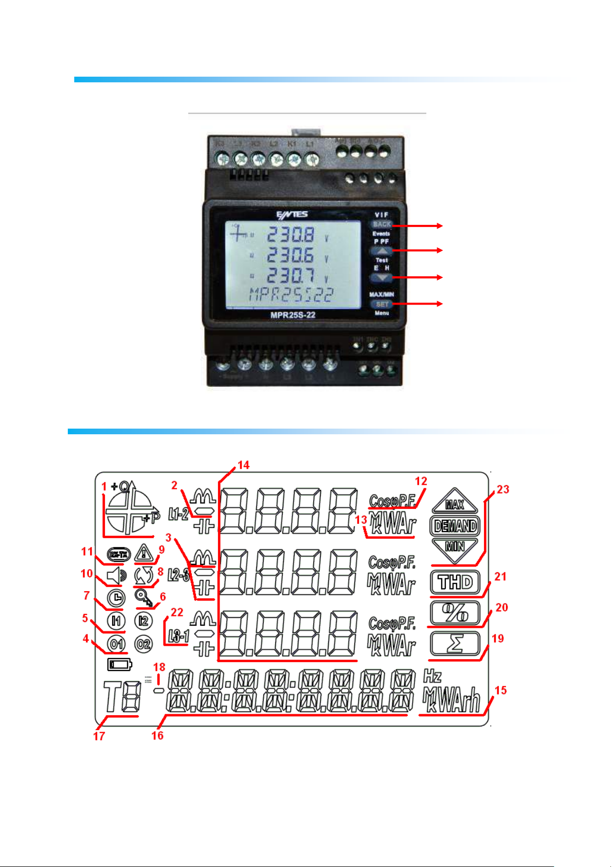
The appearance of the Device Interface is as below:
LCD Symbols
1. Displays the region where the main runs.
2. Indicates that the displayed value is negative.
3. Displays that the measurement is inductive or capacitive.
8

4. Displays that the digital output is active.
5. Displays that the pulse input is active.
6. Flashes if password is needed while entering the programming menu.
7. Flashes if RTC is reset and stays on until the RTC is set.
8. Indicates that there is a phase sequence fault.
9. Indicates that there is a warning.
10. Flashes when the alarm output is active.
11. Indicates that the communication is active.
12. Indicates that the measurement is Power Factor or Cos φ.
13. Displays the unit of the measurement value.(W, kVAr, MVA, v.s.)
14. Displays the measurement results of the related screen.
15. Displays the unit of the energy or the related setting.
16. Displays the energy value or time.
17. Indicates the tariff of the energy value.
18. Indicates that the energy value is negative.
19. Indicates that the related screen is the total screen. (For Example : Total powers)
20. Indicates that the related screen is the percentage screen. (For Example : Harmonic)
21. Indicates that the related screen is the Total Harmonic Distortion Screen.
22. Indicates the L1, L2, L3 ve L1-2, L2-3 and L3-1 measurements.
23. Indicates that the related screen is one of the Minimum, Maximum, Demand or Maximum
Demand screens.
Button Functions
4 buttons are used on the front panel. All the buttons used here can be used for additional functions
other than their main functions which can be accessed by pushing for 3 seconds. Button function
descriptions are as below.
BACK button (24): has 3 basic functions:
o Used for returning to an upper menu from any menu.
o As it can be seen from the notation on the button (V I F), it is used for monitoring the
Current, Voltage, Frequency and time counter values and switching between the related
screens.
o If, pushed for 3 seconds, it turns into device incident log monitoring mode.
UP button (25): has 3 basic functions:
o As it can be seen from the notation on the button (P PF), it is used for monitoring the
Total, Active, Reactive, Apparent Power, Cos φ and the values measured related with the
Power Factor.
o While, you are in a menu, it is used for moving upwards in a menu and increasing the
adjusted values.
o If, pushed for 3 seconds, the device switches into the connection test mode.
DOWN button (26): has 2 basic functions:
o As it can be seen from the notation on the button (E H), it is used for monitoring Harmonic
measurements on the Voltage-Current screen and Energy measurements on the Power
screen.
o While, you are in a menu, it is used for moving downwards in a menu and decreasing the
adjusted values.
SET button (27): has 3 basic functions:
o As it can be seen from the notation on the button (Max/Min), it is used for monitoring the
Maximum, Minimum, Demand and Max Demand measurements of the related screen
while you are on the Voltage-Current and Power screens.
o If, pushed 3 seconds, the settings screen is accessed. If, the PIN is active PIN is
requested to enter the Menu and the menu is accessed only if the correct PIN value is
entered.
o It is used to access the setting to be changed and save the changes, if it is required to
make changes on the settings by using the menu steps. It is enough to push the button
for a little while for this process.
9
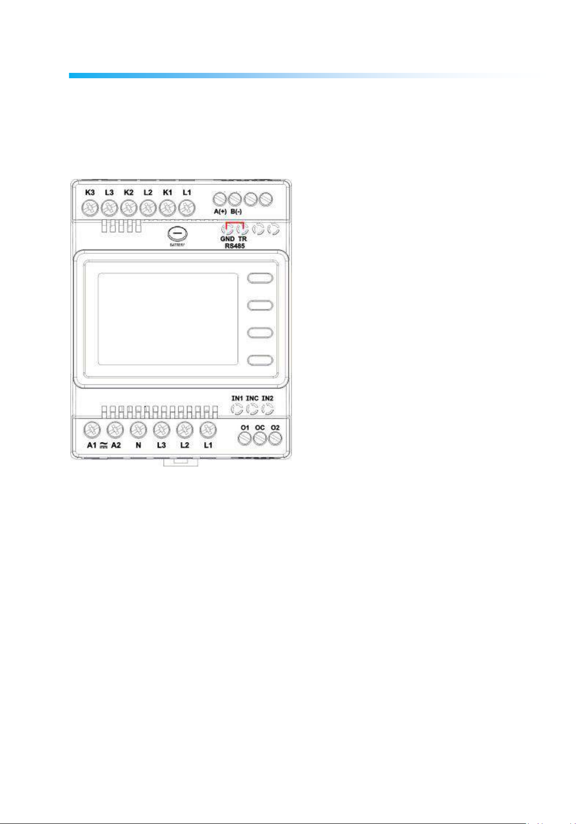
Terminal Structures
The terminal structures according to the models are described in this section:
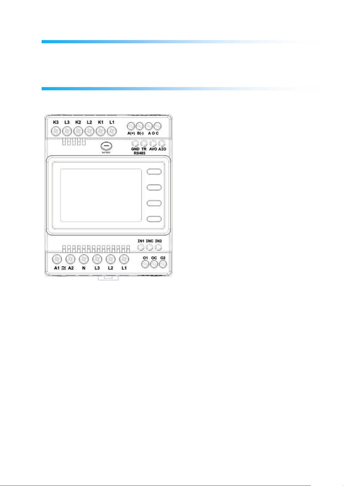
Structure of the MPR-27S-23 Terminal:
Current Terminals: K1, L1, K2, L2, K3, L3
An external current transformer must be used for the 3-phase system connection to
these terminals where the current up to 5A can be input.
Supply Terminals: A1, A2
Please, apply 85-300 VAC/DC supply connection through these terminals.
Voltage Terminals: N, L1, L2, L3
Please, apply 3-phase voltage connection through these terminals.
Digital Input Terminals: INC, IN1, IN2
As the INC terminal will be the joint point (reference), the IN1 and IN2 inputs are used
as digital inputs between 5-30 VDC. Inputs have 1 kV insulation level.
Digital Output Terminals: OC, O1, O2
10
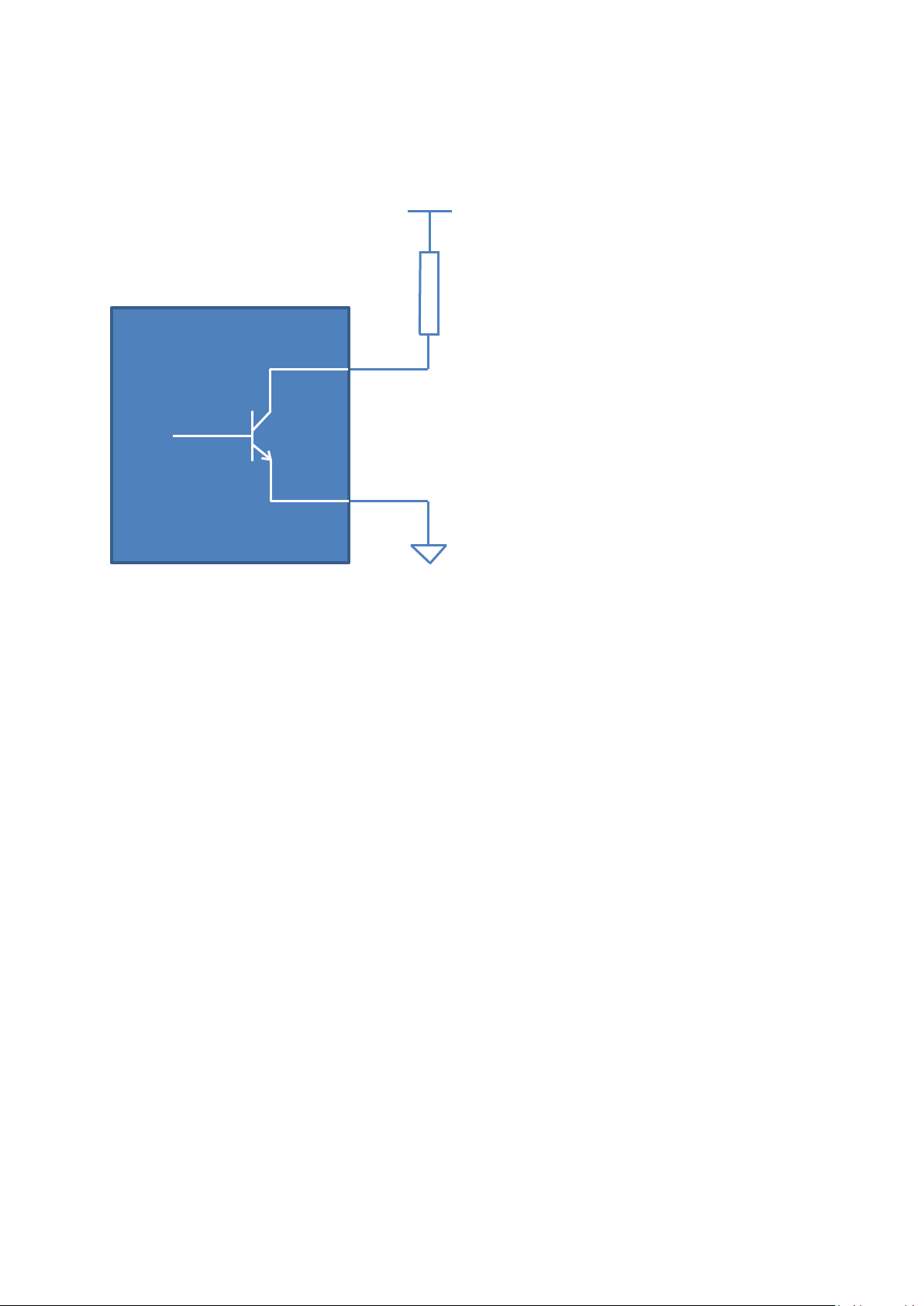
As the OC terminal will be the joint point (reference), the O1 and O2 terminals are used
5-30 VDC
Relay Coil
MPR 2X
OC
O1
O2
as insulated outputs. As it can be seen from the following figure, these Open Collector
outputs should be fed by an external supply for operation.
Analog Output Terminals: AOC, AVO, AIO
As the AOC terminal will be the joint point (reference), the analogue current or voltage
output is ensured respectively through the AIO and AVO terminals. Only one of the
AVO and AIO terminals are used at the same time.
Communication Terminals: A(+), B(-), GND, TR
RS-485 communication terminals are used for A(+) and B(-) communication
connection. As the communication distance becomes longer, the TR terminal and GND
terminal are short-circuited and 120 ohm line termination resistance is activated and
line stabilization is completed.
11
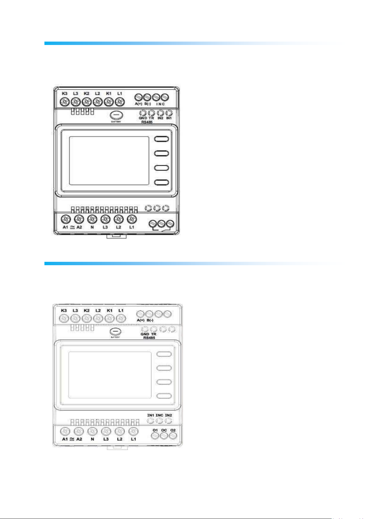
Structure of the MPR-26S-21 Terminal:
Different from the MPR27S-23, these terminals which are used for relay output are the
terminals next to the voltage terminals. They are indicated with the key symbol on the
front view. The terminal structure of the MPR26S-21 model is as in the following:
Structure of the MPR-25S-22 Terminal:
Different from the MPR27S-23, there is not any analogue output terminals on the
MPR25S-22 model. The terminal structure of the MPR25S-22 model is as in the
following:
12
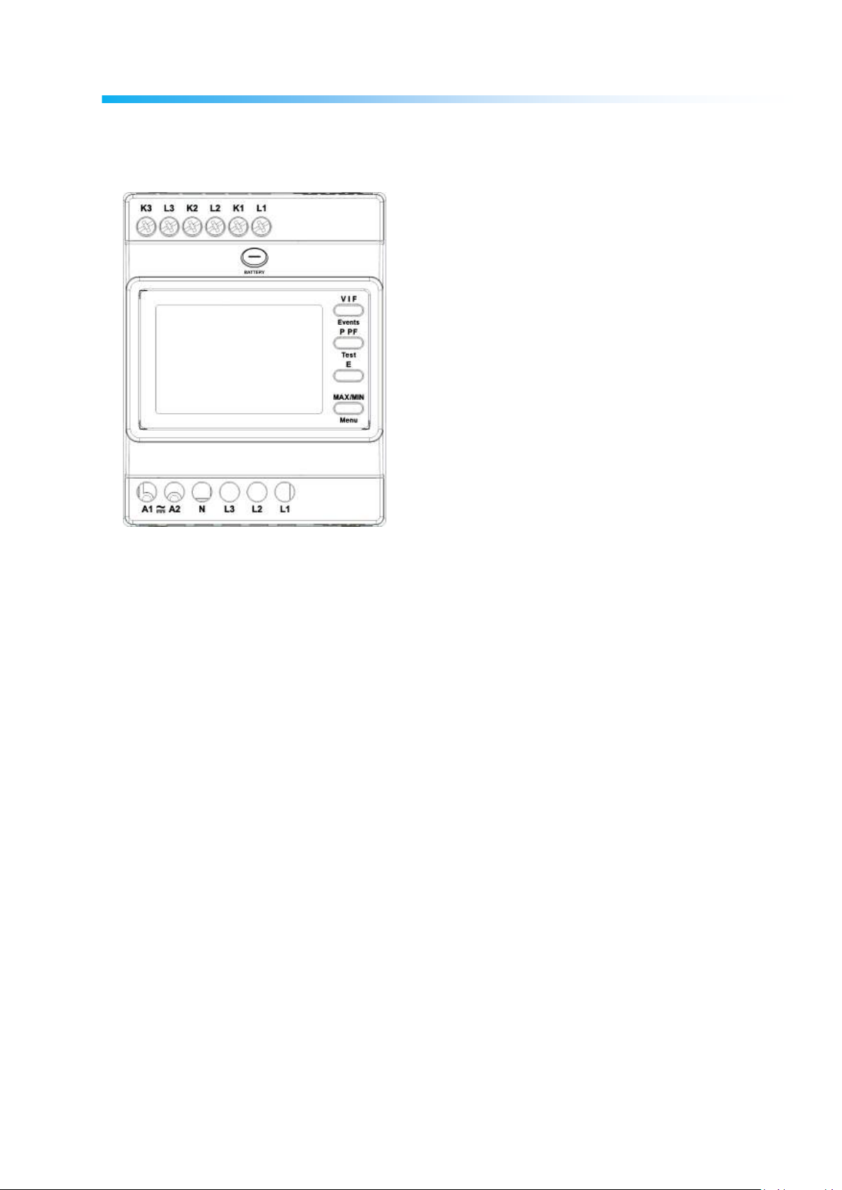
Structure of the MPR-24S Terminal:
Different from the other terminal models, MPR24S model dost not have any I/O
terminal. This terminal has only supply and measurement terminals. The terminal
structure of the MPR24S model is as in the following:
13
CONNECTION TYPES
As there are shunts at the current measurement inputs of the device, it is mandatory to use a current
transformer except for the connections of current inputs. If, the device will be used on the same current
line by means of analyzers with other shunts, it is recommended that the device is located at the extreme
point.
The device has 5 different connection types. These connection types are described in the following
schemes:
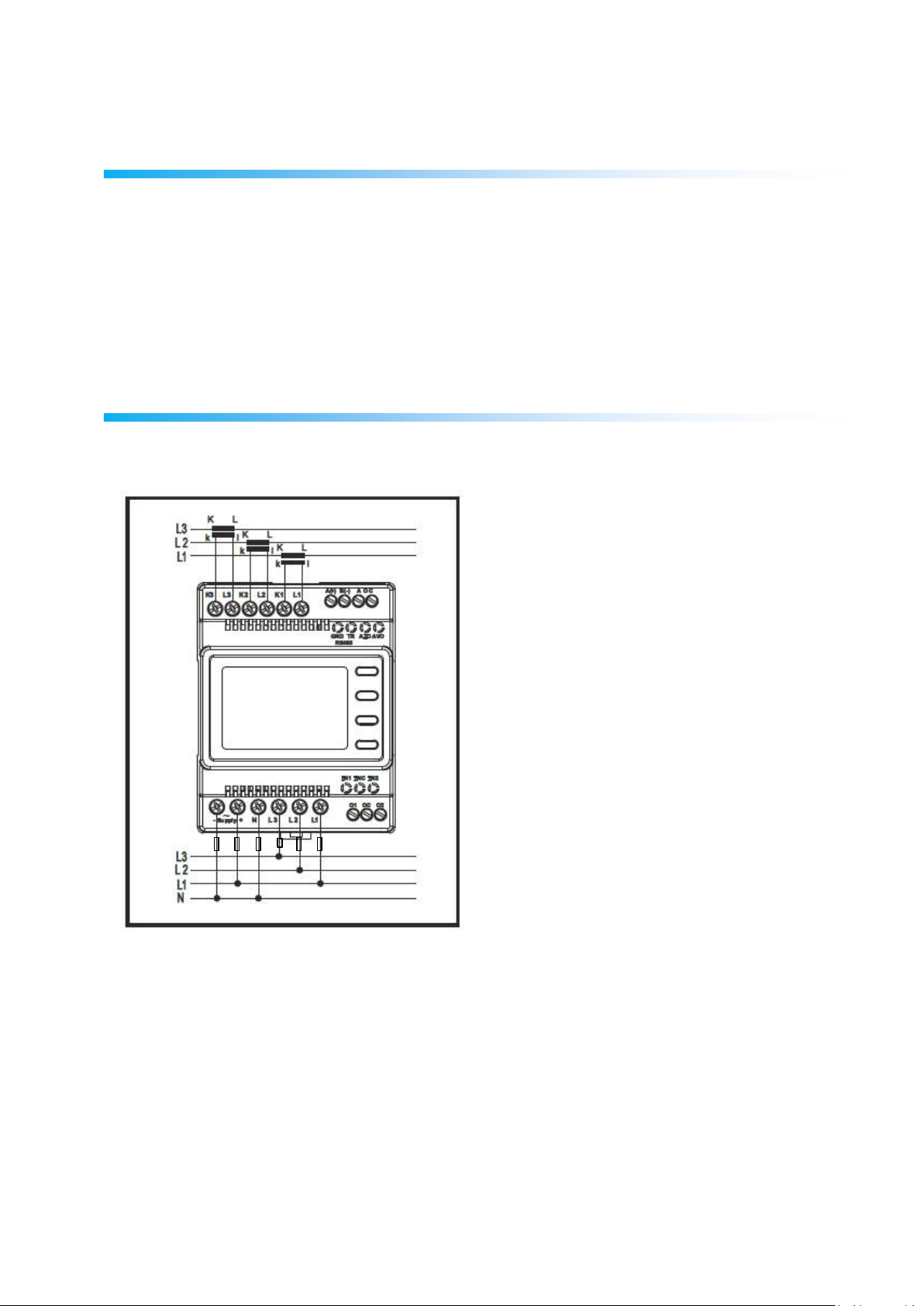
3P4W (Three-Phase Four-Wire) Connection
As it is seen below, four voltage and three current connections including the neutral line are established
in this connection type. Voltage inputs should be connected with 100 mA fuses as shown below.
14

3P3W (Three-Phase Three-Wire) Connection
As it is seen below, three voltage and three current connections are established in this connection type.
ARON Connection
Three voltage and two current connections are established in this connection type. As it is seen in the
following figure, the current connections are established with the 1st and 3rd phases.
15
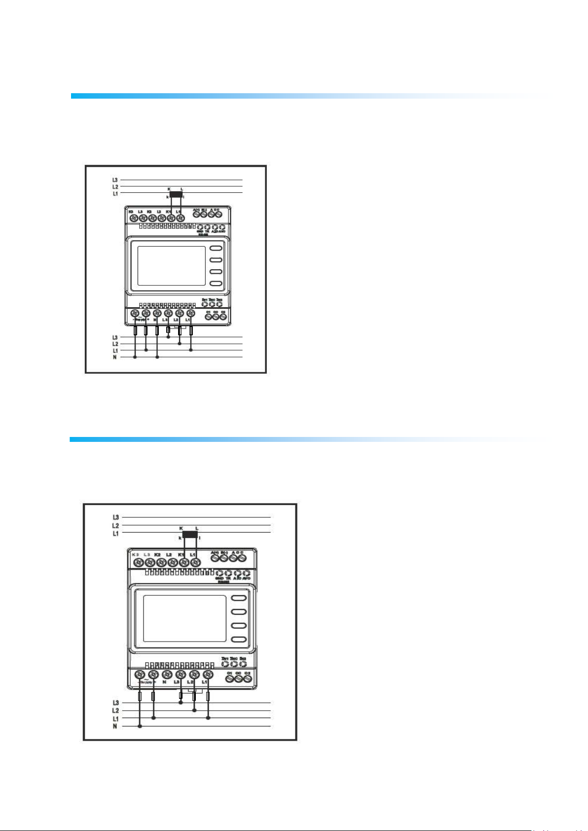
3P4W BLN (Three-Phase Four-Wire Balanced)
Connection
Four voltages and one current connection are established in this connection type. The device displays
the value measured at the current input connected to the first phase on its screen for other phases in the
same value.
3P3W BLN (Three-Phase Three-Wire Balanced)
Connection
Three voltage and one current connections are established in this connection type. As it is seen below,
the device displays the value measured at the current input connected to the first phase on its screen for
other phases in the same value.
16

Connection Control
Test Fault Code
Description
0
All connections are correct
1
Reverse Phase-1 current direction
2
Reverse Phase-2 current direction
3
Reverse Phase-3 current direction
4
Reverse Voltage connection of Phase-1 and Phase-2
5
Reverse Voltage connection of Phase-1 and Phase-3
6
Reverse Voltage connection of Phase-2 and Phase-3
7
The Phase sequence of voltage connection as L1, L2, L3 will be changed as L3,
L1, L2.
8
The Phase sequence of voltage connection as L3, L2, L1 will be changed as L3,
L1, L2.
9
CT-1, CT-2 will be changed.
10
CT-1, CT-3 will be changed.
11
CT-2, CT-3 will be changed.
12
The load value needed for minimum test conditions cannot be provided.
After, the connections of the device are completed, you can check the connection you established by
using the test functionality.
The device switches into the connection test mode if the BACK button is pushed for 3 seconds. In this
mode, at least 20% of the normal voltage and 10% of the nominal current must be applied on the
measurement inputs of the device and the angle difference between the voltage and current inputs
should be lower than 30 degrees. In other words, this control can be provided for the loads over 0.87
Cos Fi value.
In this mode, the device can control the connections and if there is any fault through the current flow
directions, it can correct such faults by software or leave it to be handled manually by the operator.
If, there is any connection fault between voltage inputs, this fault can only be corrected by changing the
cable connection points.
If, you experience the fault number 12, please make sure that all connections are established and the
aforementioned minimum current and voltage values are applied on the device.
The possible connection faults as a result of the connection test process and the codes displayed on the
device screen for these faults are indicated in the following table:
17
Communication Line Termination Resistance
If, the communication distance of RS485 lines is longer than 10 meters and there are more than one
devices on the line, a 120 Ω line termination resistance should be installed between the A and B ends of
the farthest device of the communication terminal.
For this process, as it is seen from the following figure, it is enough to short-circuit the GND and TR
terminals of the device.
18
OPERATING DEVICE
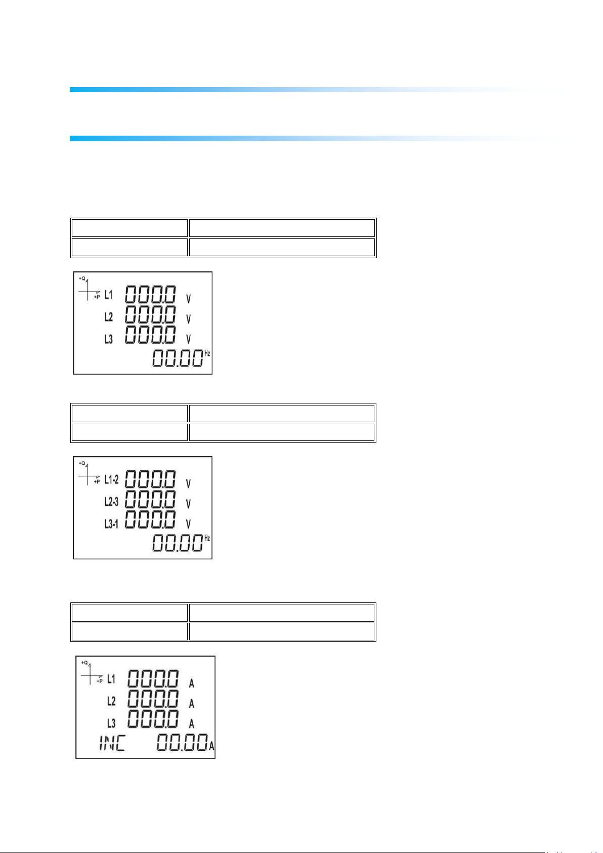
NAME OF THE BUTTON
DISPLAYED MEASUREMENT SCREEN
BACK (VIF)
VOLTAGE (L-N)
NAME OF THE BUTTON
DISPLAYED MEASUREMENT SCREEN
BACK (VIF)
VOLTAGE (L-L)
NAME OF THE BUTTON
DISPLAYED MEASUREMENT SCREEN
BACK (VIF)
CURRENT
Instant Measurement Screens
In this section, the screens which will be displayed by the buttons of the device while the device is in the
measurement mode are described.
Current, Voltage and Frequency Screens
19

NAME OF THE BUTTON
DISPLAYED MEASUREMENT SCREEN
BACK (VIF)
HOUR COUNTER 2
NAME OF THE BUTTON
DISPLAYED MEASUREMENT SCREEN
BACK (VIF)
VOLTAGE UNBALANCE
NAME OF THE BUTTON
DISPLAYED MEASUREMENT SCREEN
BACK (VIF)
CURRENT UNBALANCE
NAME OF THE BUTTON
DISPLAYED MEASUREMENT SCREEN
BACK (VIF)
HOUR COUNTER 1
20

NAME OF THE BUTTON
DISPLAYED MEASUREMENT SCREEN
DOWN (P PF)
TOTAL POWERS
NAME OF THE BUTTON
DISPLAYED MEASUREMENT SCREEN
DOWN (P PF)
ACTIVE POWER
NAME OF THE BUTTON
DISPLAYED MEASUREMENT SCREEN
DOWN (P PF)
REACTIVE POWER
Power and Power Factor Screens
21

NAME OF THE BUTTON
DISPLAYED MEASUREMENT SCREEN
DOWN (P PF)
APPARENT POWER
NAME OF THE BUTTON
DISPLAYED MEASUREMENT SCREEN
DOWN (P PF)
POWER FACTOR
NAME OF THE BUTTON
DISPLAYED MEASUREMENT SCREEN
DOWN (P PF)
COS φ
22

NAME OF THE BUTTON
DISPLAYED MEASUREMENT SCREEN
UP (E H)
THD L-N
NAME OF THE BUTTON
DISPLAYED MEASUREMENT SCREEN
UP (E H)
THD L-L
NAME OF THE BUTTON
DISPLAYED MEASUREMENT SCREEN
UP (E H)
THD IN
Energy and Harmonic Screens
23

NAME OF THE BUTTON
DISPLAYED MEASUREMENT SCREEN
UP (E H)
IMPORT ACTIVE ENERGY
NAME OF THE BUTTON
DISPLAYED MEASUREMENT SCREEN
UP (E H)
EXPORT ACTIVE ENERGY
NAME OF THE BUTTON
DISPLAYED MEASUREMENT SCREEN
UP (E H)
IMPORT REACTIVE ENERGY
NAME OF THE BUTTON
DISPLAYED MEASUREMENT SCREEN
UP (E H)
EXPORT REACTIVE ENERGY
24

NAME OF THE BUTTON
DISPLAYED MEASUREMENT SCREEN
UP (E H)
APPARENT ENERGY
NAME OF THE BUTTON
DISPLAYED MEASUREMENT SCREEN
UP (E H)
T1 TARIFF ENERGY
NAME OF THE BUTTON
DISPLAYED MEASUREMENT SCREEN
UP (E H)
GENERATOR ENERGY
NAME OF THE BUTTON
DISPLAYED MEASUREMENT SCREEN
UP (E H)
TIME
25

NAME OF THE BUTTON
DISPLAYED MEASUREMENT SCREEN
UP (E H)
DATE
NAME OF THE BUTTON
DISPLAYED MEASUREMENT SCREEN
SET (MAX/MIN)
MAX(PHASE-NEUTRAL VOLTAGE)
NAME OF THE BUTTON
DISPLAYED MEASUREMENT SCREEN
SET (MAX/MIN)
MIN(PHASE-NEUTRAL VOLTAGE)
Minimum, Maximum and Demand Screens
Please, first select the related screen by V I F button in order to see the minimum and maximum values
of current and voltage.
Then, push SET button and you can see the related screens of MAX/MIN DEMAND.
26

NAME OF THE BUTTON
DISPLAYED MEASUREMENT SCREEN
SET (MAX/MIN)
MAX(PHASE-PHASE VOLTAGE)
NAME OF THE BUTTON
DISPLAYED MEASUREMENT SCREEN
SET (MAX/MIN)
MIN(PHASE-PHASE VOLTAGE)
NAME OF THE BUTTON
DISPLAYED MEASUREMENT SCREEN
SET (MAX/MIN)
CURRENT DEMAND
NAME OF THE BUTTON
DISPLAYED MEASUREMENT SCREEN
SET (MAX/MIN)
MAXIMUM CURRENT DEMAND
27

NAME OF THE BUTTON
DISPLAYED MEASUREMENT SCREEN
SET (MAX/MIN)
MAXIMUM CURRENT
NAME OF THE BUTTON
DISPLAYED MEASUREMENT SCREEN
SET (MAX/MIN)
MINIMUM CURRENT
NAME OF THE BUTTON
DISPLAYED MEASUREMENT SCREEN
SET (MAX/MIN)
ACTIVE POWER DEMAND
Please, first select the related screen by the P PF button in order to see the minimum, maximum and
demand values of the power values.
Then, push SET button and you can access the related screens of MAX/MIN DEMAND.
28

NAME OF THE BUTTON
DISPLAYED MEASUREMENT SCREEN
SET (MAX/MIN)
MAXIMUM ACTIVE POWER DEMAND
NAME OF THE BUTTON
DISPLAYED MEASUREMENT SCREEN
SET (MAX/MIN)
MAXIMUM ACTIVE POWER
NAME OF THE BUTTON
DISPLAYED MEASUREMENT SCREEN
SET (MAX/MIN)
MINIMUM ACTIVE POWER
NAME OF THE BUTTON
DISPLAYED MEASUREMENT SCREEN
SET (MAX/MIN)
MAXIMUM REACTIVE POWER
29

NAME OF THE BUTTON
DISPLAYED MEASUREMENT SCREEN
SET (MAX/MIN)
MINIMUM REACTIVE POWER
NAME OF THE BUTTON
DISPLAYED MEASUREMENT SCREEN
SET (MAX/MIN)
APPARENT POWER DEMAND
NAME OF THE BUTTON
DISPLAYED MEASUREMENT SCREEN
SET (MAX/MIN)
MAXIMUM APPARENT POWER DEMAND
NAME OF THE BUTTON
DISPLAYED MEASUREMENT SCREEN
SET (MAX/MIN)
MAXIMUM APPARENT POWER
30

NAME OF THE BUTTON
DISPLAYED MEASUREMENT SCREEN
SET (MAX/MIN)
MINIMUM APPARENT POWER
Settings Screen
Access to the Programming Menu:
The password input screen is displayed if the SET button of the device is pushed for 3 seconds.
When, the correct programming menu password is entered, the programming menus are accessed.
Factory default device menu password is 1234.
Installation Settings of the Device
The current transformer and voltage transformer rates of the device installed in the system should be
programmed in order the device to become ready for use.
As factory default, the device is ready for applying these settings.
Please, use the SET button and down/up arrow buttons and set the following values.
Language Setting
The messages indicated on the device screen can be displayed in four different languages. These are;
1. Turkish
2. English
3. German
4. French.
Apply the desired language setting by using the down and up arrow buttons and switch the next setting
by SET button.
31

Mains Connection Type Setting
1. Please, select one of the system connection types from 3F4T, 3F3T, ARON, 3F4T Balanced or
3F3T Balanced by means of the down and up arrow buttons.
2. 3F4T and 3F3T types should be preferred for imbalanced systems.
3. Switch to the next setting by the SET button.
Voltage Transformer Presence Setting
1. By means of the down and up arrow buttons, determine whether there is any voltage transformer
connected to the system by using Active and Passive options.
2. Switch to the next setting by the SET button.
Voltage Transformer Secondary Setting
1. Adjust the Secondary value of the Voltage transformer by using the SET, down and up arrow
buttons.
2. You can switch between the value digits by means of the SET button.
3. Switch to the next setting by the SET button after adjusting the desired value.
32

Voltage Transformer Primary Setting
1. Adjust the desired primary voltage value from 50 to 400.000 by using the down and up arrow
buttons.
2. You can use the SET button for switching between the digits.
3. Switch to the next setting by the SET button after adjusting the desired value.
Current Transformer Secondary Setting
1. Select the secondary value of current transformer from 1A or 5A values by using the down and
up arrow buttons.
2. Switch to the next setting by the SET button after adjusting the desired value.
Current Transformer Primary Setting
1. Adjust the desired current transformer primary value from 1~9999A value range by pushing the
SET button.
2. You can use the SET button for switching between the digits.
3. Switch to the next setting by the SET button after adjusting the desired value.
33

Nominal Frequency Setting
1. Please, select the nominal operating frequency of the device as 50 Hz or 60 Hz.
2. Switch to the next setting by the SET button after adjusting the desired value.
Nominal Operating Voltage Setting
1. The nominal operating voltage of the device can be selected from 25V to 300V.
2. You can use the SET button for switching between the digits.
3. Switch to the next setting by the SET button after adjusting the desired value.
Time Zone Setting
1. You can select the regional time zone of the device in 30 minutes intervals in between -12:00
and +12:00 hours.
2. Switch to the next setting by the SET button after adjusting the desired value.
Date Setting
34

1. Please, use the SET, down and up arrow buttons for setting the date.
2. You can use the SET button for switching between the digits.
3. Switch to the next setting by the SET button after adjusting the desired value.
Time Setting
1. Please, use the SET, down and up arrow buttons for setting the time.
2. You can use the SET button for switching between the digits.
3. Switch to the next setting by the SET button after adjusting the desired value.
After, completing the factory settings, the device switches to the measurement screens. The
settings which you desire to change later can be revised from the settings menu by pushing the
SET button for 3 seconds.
Display Settings
There are the language selection, display contrast and backlight setting in the display settings section of
the device.
Language Selection
The device can be set into four different languages. These are;
1. Turkish
2. English
3. German
4. French.
1. Push set button by selecting the Language tab in the Settings, Display menu.
2. The current language selection begins flashing. Select one of the options above and push SET button.
3. Do not forget to save the adjusted settings before leaving the menu by means of the BACK button.
Backlight Setting
35

There are three different options for the display backlight setting:
1. Always open,
2. Always closed,
3. Automatic
When, the automatic option is selected, the backlight turns off almost 3 minutes after any button is
pushed.
1. Push set button by selecting the Backlight tab in the Settings, Display menu.
2. The current backlight selection begins flashing. Select one of the options above and push SET
button.
3. Do not forget to save the adjusted settings before leaving the menu by means of the BACK
button.
Display Contrast Setting
The display contrast of the device can be set in 16 different levels from 0 to 15.
The factory default value is 3.
1. Push set button by selecting the Contrast tab in the Settings, Display menu.
2. The current Contrast selection begins flashing. Please, select a value from 0-15 and push the SET
button.
3. Do not forget to save the adjusted settings before leaving the menu by means of the BACK button.
Time Settings
Time Setting
The hour, minute and second adjustments of the RTC (Real Time Clock) module of the device can be
applied by pushing the SET button.
36

The phases of this process:
1. Push the SET button while you are on the clock screen.
2. Push the SET button on the Time Settings screen which is the first displayed screen of the
menu.
3. In this section, the clock section begins flashing.
4. Adjust the desired time value by using the down and up arrow buttons.
5. Adjust the minute and second sections to the desired values by switching with the SET button.
6. The entered parameters will be automatically saved while you are leaving the menu by pushing
the BACK button.
Date Setting
The date setting of the RTC module of the device can be adjusted by pushing the SET button.
The phases of this process:
1. Push the SET button while you are on the Date Settings screen.
2. Determine the calendar day by pushing the SET button and using the down and up arrow
buttons.
3. Determine the calendar month by pushing the SET button and using the down and up arrow
buttons.
4. Determine the calendar year by pushing the SET button and using the down and up arrow
buttons.
5. The entered date will be automatically saved while you are leaving the menu by pushing the
BACK button.
Time Zone Setting
1. Push the SET button while you are on the Time Zone screen.
37

2. The chosen Time Zone is displayed on the screen.
3. Enter the menu by pushing the SET button.
4. You can determine the time zone of the desired region in half hours by using the down and up
arrow buttons.
5. Push the SET button after completing your selections.
6. Do not forget to save the adjusted settings before leaving the menu by means of the BACK
button.
Summer Time Mode Setting
1. Push the SET button while you are on the Summer Time mode screen.
2. The Summer Time screen is displayed.
3. Select one of the EUROPE, USA, Special Settings and Closed setting by pushing the SET
button.
4. If, you choose the Special Setting mode, the beginning month, week, day and time of the
Summer Time are adjusted by pushing the SET button.
5. If, the SET button is pushed again, the ending month, week, day and time of the Summer Time
are adjusted by pushing the SET button.
6. After, the desired values are adjusted, please push the SET button and leave this menu.
7. Do not forget to save the adjusted settings before leaving the menu by means of the BACK
button.
RS-485 Communication Settings
RS-485 Address Setting
1. Come to the Address menu in RS-485 settings and push the SET button.
2. The current address flashes. The address where the device is located on the RS-485 network
can be chosen in 1 to 247 range. You can adjust any value for each digit in the address menu by
means of the SET button.
3. Do not forget to save the adjusted settings before leaving the menu by means of the BACK
button.
38

RS-485 Bit Rate Setting
The RS-485 communication rate of the device can be adjusted one of the following values:
1. 2400 baud
2. 4800 baud
3. 9600 baud
4. 19200 baud
5. 38400 baud
6. 57600 baud
7. 115200 baud
1. For this process, please push the SET button while you are in the RS-485 bit rate menu.
2. Switch to the selection phase by means of the SET button while you are on the displayed
selection screen.
3. Adjust the desired value by using the down and up arrow buttons.
4. Do not forget to save your settings before leaving the menu by means of the BACK button.
RS-485 Parity Setting
The RS-485 communication parity of the device can be set to one of the values as ODD or EVEN
parity or without any parity.
The factory default value is NO Parity.
1. For this process, please push the SET button while you are in the RS-485 Parity menu.
2. Switch to the selection phase by means of the SET button while you are on the displayed
selection screen.
3. Adjust the desired value by using the down and up arrow buttons.
4. Do not forget to save your settings before leaving the menu by means of the BACK button.
39

Input Parameter Settings
One of the following values can be selected for the input type of the device.
1. Digital input: If, this type is selected, the device senses the logic level of the input.
2. Generator input: If, this type is selected, the device can apply the energy registry to the
generator registers according to the input data.
1. For this process, please push the SET button while you are in the Input menu.
2. Switch to the selection phase by means of the SET button while you are on the displayed
selection screen.
3. Adjust the desired value by using the down and up arrow buttons.
4. Do not forget to save your settings before leaving the menu by means of the BACK button.
Output Parameter Settings
The digital output of the device can be used for one of the following values:
1. Output according to the pulse selection. In this option, the device generates output pulses
according to the selected size of the active and reactive energy.
2. Output according to the alarm. In this option, if the parameter set as the alarm source exceeds
the threshold level, the device output is automatically changed from logic-1 level to the logic-0
level.
When, the alarm condition disappears, the device turns into the logic-1 level.
40

3. Output according to the remote selection. In this option, the user can set the output of the device
as logic-0 or logic-1 in accordance with the RS-485 protocol.
By this way, the user can remotely turn on/off any circuit.
1. For this process, please push the SET button while you are in the Output menu.
2. Switch to the selection phase by means of the SET button while you are on the displayed
selection screen.
3. Adjust the desired value by using the down and up arrow buttons.
4. Do not forget to save your settings before leaving the menu by means of the BACK button.
Pulse Output Settings
Pulse output according to Active Energy
1. Push the up arrow button while the PuLS O-1 PArA is selected on the screen.
2. Choose the energy value which the device generates an output pulse as indicated in the screens
above. Choose the one on left for total import and the one on right for total export active energy.
3. Exit from the menu after completing your selection.
4. Do not forget to save your settings before leaving the menu by means of the BACK button.
After, the output according to the pulse selection is chosen from the parameter settings, the pulse output
setting according to active energy can be adjusted.
The device can generate pulses as much as the following steps of the import or export active energy:
1. 1 Wh
41

2. 10 Wh
3. 100 Wh
4. 1 kWh
5. 10 kWh
6. 100 kWh
7. 1 MWh.
Pulse output according to Reactive Energy
1. Push the SET button while the PuLS O-1 PArA is selected on the screen.
2. Choose the energy value according to the desired section which the device generates an output
pulse as indicated in the screens above.
3. Exit from the menu after completing your selection.
4. Do not forget to save your settings before leaving the menu by means of the BACK button.
As it is seen from the figures, the energy regions can be selected for different quadrant sections.
The device can generate pulses as much as the following steps of the import or export reactive energy:
1. 1 Varh
2. 10 Varh
3. 100 Varh
4. 1 kVarh
5. 10 kVarh
6. 100 kVarh.
7. 1 MVarh
Time Setting for Pulse Output
In this section, the time that the pulse will stay at the logic-0 level is set.
42

1. Push the SET button while the PulS dUrAtIon is selected on the screen.
2. Select the pulse width to be generated by the device in 0.01 second steps as shown in the screen
above.
3. Exit from the menu after completing your selection.
4. Do not forget to save your settings before leaving the menu by means of the BACK button.
Pulse Duty Factor Adjustment for Pulse Output
In this section, the time that the pulse will stay at the logic-1 level is set.
1. Push the SET button while the PULSE dUtY is selected on the screen.
2. Select the duty factor of the pulse to be generated by the device in 0.01 second steps as shown in
the screen above.
3. Exit from the menu after completing your selection.
4. Do not forget to save your settings before leaving the menu by means of the BACK button.
Operating Time Settings
In this section, it is described that the time passes where the device exceeds an adjusted value of a
chosen parameter.
The parameter is selected from the Time counter screen of the programming menu. For example, if VLN
is selected, the screen is displayed as below.
43

1. Push the SET button while the HoUr CoUn PArA is selected on the screen.
2. Select the parameter where the time counter will start.
3. Switch to the next setting by the SET button after making your choice.
Then, the level which this selected parameter will start the time counter is exceeded is determined.
1. As it is seen above, while the level screen of the selected parameter is chosen, push the SET
button.
2. Enter the appropriate level value digit by digit. You can switch between the digits by means of
the SET button.
3. Exit from the menu after completing your selection.
4. Do not forget to save your settings before leaving the menu by means of the BACK button.
Alarm Settings
The parameters of 4 different alarms of the device can be adjusted separately.
The processes described for an alarm in the following section are the same for all 4 alarms.
Activating the Alarm
Follow the following steps for activating an alarm:
1. Push SET while your are in the Setup Alarm menu.
44

2. If, SET button is pushed while, you are in the Alarm Enable screen, you can select it as enable
or disable by the down and up arrow buttons.
3. Push the SET button after making your choice.
4. Do not forget to save your settings before leaving the menu by means of the BACK button.
Selecting Alarm Parameters
Follow the steps below for selecting alarm parameters:
1. Push SET while your are in the Setup Alarm menu.
2. Switch to the Alarm parameters screen by pushing the down button.
3. Activate an alarm parameter by pushing the SET button.
4. Set the alarm parameter one of the following options by means of the down and up arrow
buttons:
a. Phase currents
b. Total current
c. Current demand
d. Total current demand
e. Active Power
f. Reactive Power
g. Apparent Power
h. Total Active Power
i. Total Reactive Power
j. Total Apparent Power
k. Active power demand
l. Apparent power demand
m. Total Active Power Demand
n. Total Apparent Power Demand
o. Cos phi
p. Total Cos phi
q. Frequency
r. THDV
s. THDU
t. THDI
u. Time counter
v. Digital input
w. Tariffs
x. Phase Neutral Voltage
y. Phase to Phase Voltage
5. Push the SET button after completing your selections.
45

Alarm Operating Method Settings
1. Push the SET button for selecting the alarm operation method.
2. In this mode, select one of the following options:
a. In the window
b. Out of the window
c. Greater than the value
d. Smaller than the value
3. When, in and out of the window are selected, the low and high threshold levels are set.
4. The high threshold level is set for the greater than value option while the low threshold level is
set for smaller than the value option is selected.
5. Do not forget to save your settings before leaving the menu by means of the BACK button.
Alarm High Level Setting
In this mode, the high level value required for defining an alarm is set.
1. While Alarm Enable is chosen, Alarm High screen can be seen by pushing the up arrow button.
2. Set the desired high level value by using the SET button and the direction buttons.
3. Push the SET button after completing your selections.
4. You can save alarm parameters separately for 4 different alarms.
5. Do not forget to save your settings before leaving the menu by means of the BACK button.
Alarm Low Level Setting
In this mode, the low level value required for defining an alarm is set.
1. While, the Alarm Enable is chosen, switch to the Alarm Low screen by pushing the up arrow
button.
2. Set the desired low level value by using the SET button and the direction buttons.
3. Push the SET button after completing your selections.
46

4. You can save alarm parameters separately for 4 different alarms.
5. Do not forget to save your settings before leaving the menu by means of the BACK button.
Hysteresis Setting of the Alarm
In this mode, the hysteresis value required for defining an alarm is set. This setting is done in order to
prevent that the device does not continuously turns into alarm mode in little changes around the
threshold level. As in the following example, when the 2% value is selected, the alarm parameter value
should be changed at 2% in order to get out of the alarm mode.
1. While, the Alarm Enable is chosen, switch to the Alarm Hyst screen by pushing the up arrow
button.
2. Set the desired Hysteresis value in % by using the SET button and the direction buttons.
3. Push the SET button after completing your selections.
4. You can save alarm parameters separately for 4 different alarms.
5. Do not forget to save your settings before leaving the menu by means of the BACK button.
Alarm Delay Time Setting
1. After the alarm hysteresis screen, the Alarm delay time for activation is determined by pushing
the SET button.
2. The delay time in seconds is set by pushing the low and up arrow buttons and switching between
the digits through the SET button.
3. After, the Alarm source exceeds the limit, an ALARM is generated for the time adjusted at that
phase if there is any border violation.
4. The alarm release time is determined in the following screen by pushing the down arrow button.
5. The minimum time to pass for releasing an alarm is selected in the release time screen by
pushing the SET button.
6. The alarm is not released for the time where the parameter value is set here unless it exceeds
the threshold + hysteresis value.
7. Adjust the desired time value in seconds by using the down and up arrow buttons.
8. Do not forget to save your settings before leaving the menu by means of the BACK button.
47

Reset Settings
It is possible for the users to reset the minimum, maximum, demand and incident logs saved in the
device.
Resetting the maximum logs
1. Select the maximum logs from the Reset menu and push the SET button.
2. Select the "Yes" option for deleting by using the down and up arrow buttons in the "Reset
Maximum" section shown on the screen.
3. Finalize your input by the SET button.
4. Do not forget to save your settings before leaving the menu by means of the BACK button.
Resetting the minimum logs
1. Select the minimum logs from the Reset menu and push the SET button.
2. Select the "Yes" option for reset by using the down and up arrow buttons in the "Reset Minimum"
section shown on the screen.
3. Finalize your input by the SET button.
4. Do not forget to save your settings before leaving the menu by means of the BACK button.
Resetting the demand logs
1. Select the demand logs from the Reset menu and push the SET button.
2. Select the "Yes" option for deleting by using the down and up arrow buttons in the "Reset
Demand" section shown on the screen.
3. Finalize your input by the SET button.
4. Do not forget to save your settings before leaving the menu by means of the BACK button.
48

Resetting the Maximum Demand logs
1. Select the max demand logs from the Reset menu and push the SET button.
2. Select the "Yes" option for deleting by using the down and up arrow buttons in the "Reset Max
Demand" section shown on the screen.
3. Finalize your input by the SET button.
4. Do not forget to save your settings before leaving the menu by means of the BACK button.
Resetting the energy logs
1. Select the energy logs from the Reset menu and push the SET button.
2. Select the "Yes" option for deleting by using the down and up arrow buttons in the "Reset
Energy" section shown on the screen.
3. Finalize your input by the SET button.
4. Do not forget to save your settings before leaving the menu by means of the BACK button.
Resetting the generator energy logs
1. Select the Gen energy logs from the Reset menu and push the SET button.
2. Select the "Yes" option for deleting by using the down and up arrow buttons in the "Reset Gen
Energy" section shown on the screen.
3. Finalize your input by the SET button.
4. Do not forget to save your settings before leaving the menu by means of the BACK button.
49

Resetting the time counter
1. Select "Time Counter" logs from the Reset menu and push the SET button.
2. Select the "Yes" option for deleting by using the down and up arrow buttons in the "Reset Time
Counter" section shown on the screen.
3. Finalize your input by the SET button.
4. Do not forget to save your settings before leaving the menu by means of the BACK button.
System Settings
Pin Code Activation
It is set whether a password is required for accessing the settings menu by the settings to be applied
in that section.
1. Push the SET button in the "Pin Request" screen of the system menu.
2. If, the SET button is pushed in the "Request PinA" section displayed on the screen, the 4-digit
PIN input screen is displayed.
3. Enter your set PIN code by using the down and up arrow buttons.
4. You can switch between the digits by pushing the SET button.
5. When, you enter the correct Pin code, the "Active" and "Passive" options are displayed on the
screen.
6. If, you save by exiting the menu after choosing the "active" option, the following menu access will
be through a password authentication.
7. Do not forget to save your settings before leaving the menu by means of the BACK button.
Factory default device menu password is 1234.
Changing the Pin Code
50

1. Push the SET button in the "Change Pin" screen of the system menu.
2. Enter the previous 4-digit PIN code by using the down and up arrow buttons.
3. If, you enter the wrong code, the "WRONG" warning is displayed on the screen.
4. If, the WRONG warning is displayed, please reenter the pin code by pushing the SET button
again.
5. If, you enter the Pin code correctly, the "Change Pin" notice is displayed.
6. In this case, determine the new 4-digit pin code and push the SET button.
7. Then, enter the same pin code for a second time and push the SET button.
8. After, you enter the pin code correctly twice, the "Pin is Changed" notice is displayed on the
screen.
9. Do not forget to save your settings while leaving the menu by BACK button. From now on, you
can use your new pin code.
Restoring the Factory Defaults
1. In order to restore the system to factory defaults, push the SET button in the "System "FBT
RESET" screen.
2. If, the SET button is pushed while, the "SIStE FB RESET" is displayed on the screen, the pin
code must be entered.
3. Enter your valid PIN code by using the down and up arrow buttons.
4. If, you enter the pin code correctly, the No text appears on the lower line of the screen.
5. In this mode, push the SET button and switch that to "Yes" mode by using the low arrow button
and then push the SET button once again.
6. Do not forget to save your settings before leaving the menu by means of the BACK button.
7. "RESETING" message is displayed on the screen while exiting the menu.
8. 3 seconds after the software version of the device is displayed on the screen and factory
defaults restore process starts.
After the settings are completed, the voltage measurement screen of the device is displayed.
Displaying the Software and Hardware Versions
In order to learn the software and hardware versions of the system, please follow the steps below:
1. Push the SET button while you are on the "System Software) screen.
2. The software version of the system is displayed on the lower line of the screen.
3. When, the SET button is pushed once again, the hardware version of the system is displayed on
the screen with "SYSTEM HARDWARE" notice.
51

Displaying the Serial Number of the Device.
1. Push the SET button while you are on the "System Serial No screen.
2. The 8-digit serial number of the device is displayed on the screen with "Serial No" notice.
Reading Logs from the Modbus
There are two ways to access the logs through the Modbus:
Log Access Based on Time
In this method, the log date desired to be accessed by the Modbus addresses beginning from 21100
address is written in Unit Time format in the related address based on the log type desired to be
accessed. The device searches and finds the closest log for the requested date and writes the index
related with that log into the index register beginning from 21200 address.
When, the user writes this index to the lowermost index register of the tables at the 23000, 24000, 25000
and etc. addresses, he/she will be able to access the details of the related log through the same tables.
A free software is prepared to read the Log data in the system and this software can be downloaded
from the following webpage:
http://www.entes.com.tr/dosyalar/Applications/Mpr3x4xLogReader/publish.htm
Log Access Based on Index
In this method, the user can write the log index number in the lowermost index register of the tables at
23000, 24000, 25000 and etc. address and access the details of the related log through the same tables.
Reporting Screen
If, you push the BACK button of the device for 3 seconds, the reports of saved incidents are displayed on
the screen.
Totally 255 incidents can be saved in the device.
The logged incident types are: First energization, short blackout for the blackouts continued less than 3
seconds, long blackout for the blackouts continued more than 3 seconds, alarm, setting change, time
change and reset.
You can switch between the saved incidents by means of the down and up arrow buttons.
52

The incidents are listed in time sequence.
The first log is listed as the newest report while the 255th log is listed as the oldest one.
By pushing the SET button you can respectively display the log's;
1. Start date,
2. Start time,
3. End date,
4. End time,
5. Duration,
6. Parameter,
7. Source of the alarm,
8. Value of the alarm.
If, no button is pushed for 60 seconds, the system turns back to the measurement screens by leaving the
incidents screen.
53

54

TECHNICAL INFORMATION AND ATTACHMENTS
Technical properties
Value
Dimensions
DIN 4
Display
LCD
Voltage measurement range
10~300 VAC(VLN) 10~480 VAC(VLL)
Measurement range with transformer
10~999 kV
Accuracy
%0.5 +/- 1 digit
Input Impedance
1.8 MΩ
Burden (Input Load)
< 0.5 VA
Current measurement accuracy
%0.5 +/- 1 digit
Nominal Current
1A, 5A
Lowest current
5 mA
Current measurement range
50 mA ~ 5,5A
Measurement range with transformer
50 mA ~ 10 kA
Burden (Input Load)
< 1 VA
Active power accuracy
%1 +/- 1 digit
Reactive power accuracy
%1 +/- 1 digit
Active energy measurement accuracy
Class 1
Reactive energy measurement accuracy
Class 2
Active power measurement range
0 ~ 1 GW
Reactive power measurement range
0 ~ 1 GVar
Apparent power measurement range
0 ~ 1 GVA
Power consumption
< 5 VA
Active energy measurement ceiling
9 999 999.9 kWh
Reactive energy measurement ceiling
9 999 999.9 kVarh
Operating voltage
95 - 270 VAC/VDC ,12 – 50 VDC (for D series)
(Tolerances up to 10%)
Operating frequency
50 - 60 Hz.
Digital input processing voltage
5 ~ 30 VDC
Digital input switching current
Maximum 50 mA
Minimum pulse time
100 ms pulse period, 80 ms pulse width
Operating Temperature Range
-10 ~ +55 ºC
Storage Temperature Range
-20 ~ +70 ºC
Maximum operating humidity
% 95
Assembly
Assembled to the wall box from the front.
Connection terminals
Screw terminal
Connection types
3 phase + neutral, 3 phase balanced, 3 phase
imbalanced, Aron.
Communication Protocol
RS-485 / MODBUS RTU
Communication Speed
2400 ~ 115200
Max. Voltage / Max. Current (For Relay)
250 VAC / 5A
Technical Information
55

IEC 61557-12 Properties
CONFORMITY IEC 61557-12 Edition 2
PMD SPECIFICATIONS
Type of Specification
Examples of possible
specification values
Other additional
specifications
Supply quality evaluation function (option)
/
/
PMD Classification
SD
/
Setpoint
K55
/
Humidity + Altitude
/
/
Operating performance class for active power or
active energy (if function availible)
0,5
/
Symbol for
functions
Measurement
range
Operating performance class,
according to CEU 61557-12
according to KI
Other additional
specifications
P
10% to 120% In
0,5
Qa, Qv
10% to 120% In
1
Sa, Sv
10% to 120% In
1
Ea
0 to 99999999 kW/h
0,5
Era, Erv
0 to 99999999 kVar/h
1
Eapa
0 to 99999999 kVA/h
0,5
f
50 - 60 Hz
0,02
I 10% to 120% In
0,2
In, Inc
10% to 120% In
0,2
U 10 to 480Vac ph/ph
0,2
Pfa, Pfv
0,5 ind to 0,8 cap
0,5
Udip, Uswl
Unavailable function
Utr
Unavailable function
Uint
Unavailable function
Unba, Unb
Unavailable function
Uh
Unavailable function
THDu
Fn=50Hz - range 1 to 50
Fn=60Hz - range 1 to 50
1
THD-Ru
Unavailable function
Ih
Unavailable function
THDi
Fn=50Hz - range 1 to 50
Fn=60Hz - range 1 to 50
1
THD-Ri
Unavailable function
Msv
Unavailable function
56

Compliance with the Standards
Standard
Year
Title
IEC 61557-
12
2008
Electrical safety in low voltage distribution systems up to 1kV (a.a.) and
1,5kV DC(d.a.) – Equipment for testing, measuring or monitoring of
protective measures - Part 10: Performance measuring and monitoring
arrangements
IEC 61326-
1
2005
Electrical equipment for measurement, control and laboratory use - EMC
requirements - Part 1: General conditions
EN 61000-
6-2
2005
Electromagnetic compatibility (emc) - Part 6-2: General standards -
Immunity for industrial environments
IEC
60050(161)
2011
International Electro-technical Vocabulary Chapter 161- Electromagnetic
Compatibility
EN 62053-
21
2003
Electricity measurement equipment (a.a.) - Special rules - Chapter 21:
Static meters for active energy (class 1 and class 2)
EN 62053-
23
2003
Electricity measurement equipment (a.a.) - Special rules - Chapter 23:
Static meters - Reactive energy (class 2 and class 3)
EN 61000-
4-2
1995
Electromagnetic compatibility (EMC) - Part 4-2: Test and measurement
techniques - Electrostatic discharge immunity test
EN 61000-
4-3
2006
Electromagnetic compatibility (emc) - Part 4-3: Test and measurement
techniques-Radiated, radio- frequency, electromagnetic field immunity
test
EN 61000-
4-4
2004
Electromagnetic compatibility (EMC) - Part 4-4: Test and measurement
techniques - Electrical fast transient/burst immunity test
EN 61000-
4-5
2006
Electromagnetic compatibility (emc) - Part 4-5: Test and measurement
techniques - Surge immunity test
EN 61000-
4-6
2007
Electromagnetic compatibility (EMC) - Part 4-6: Test and measurement
techniques - Immunity to conducted disturbances, induced by radio-
frequency fields
EN 61000-
4-8
2010
Electromagnetic compatibility (EMC) - Part 4-8: Test and measurement
techniques-Power Frequency Magnetic Field Immunity Test
EN 61000-
4-11
2004
Electromagnetic compatibility (EMC) - Part 4-11: Test and measurement
techniques - Voltage dips, short interruptions and voltage variations
immunity tests
EN 61000-
6-3
2007
Electromagnetic compatibility (EMC) - Chapter 6-3: General standards -
Emission Standard for residential, Commercial and light-industrial
environments
EN 61000-
3-2
2010
Electromagnetic compatibility (emc) - Part 3-2: Limit values - imits for
harmonic current emissions (equipment input current ≤ 16 A per phase)
EN 61000-
3-3
2011
Electromagnetic compatibility (EMC) - Part 3-3: Limits - Limitation of
voltage fluctuations and flicker in low- voltage supply systems for
equipment with rated current kleiner 16 A
57

EN 55016-
2-1
2009
Specification for radio disturbance and immunity measuring apparatus
and methods - Chapter 2-1: Methods of measurement of disturbances
and immunity - Conducted disturbance measurements
EN 60068-
2-2
2008
Basic environmental testing procedures Part 2:tests-Test B: Dry heat
EN 60068-
2-6
2007
Environment test - Chapter 2-6: Tests - Fc tests: Vibration (sinus
formed)
EN 60068-
2-30
2008
Environmental testing -- Part 2-30: Tests - test db: Damp heat, cyclic (12
h + 12 h cycle)
EN 60068-
2-31
2010
Environmental testing -- Part 2-31: Tests - test ec: Rough handling
shocks, primarily for equipment-type specimens
EN 60068-
2-75
1997
Basic Environmental Testing Procedures Part 2: Tests - test eh:
Hammer tests
BS EN
61010-1
2010
Safety requirements for electrical equipment for measurement, control
and laboratory use-Part 1:General requirements
EN 61010-
2-030
2010
Safety requirements for electrical equipment for measurement, control
and laboratory use-Part 2-030: Specific rules for test and measurement
of circuits
EN 62262
2010
Degrees of protection provided by enclosures for electrical equipment
against external mechanical impacts (IK code) / Note: Includes
Corrigendum of July 2002 (EN 50120 + A1 are renumbered as EN
62262:2002)
58
Measurement Menu Map 1
59

Measurement Menu Map 2
60

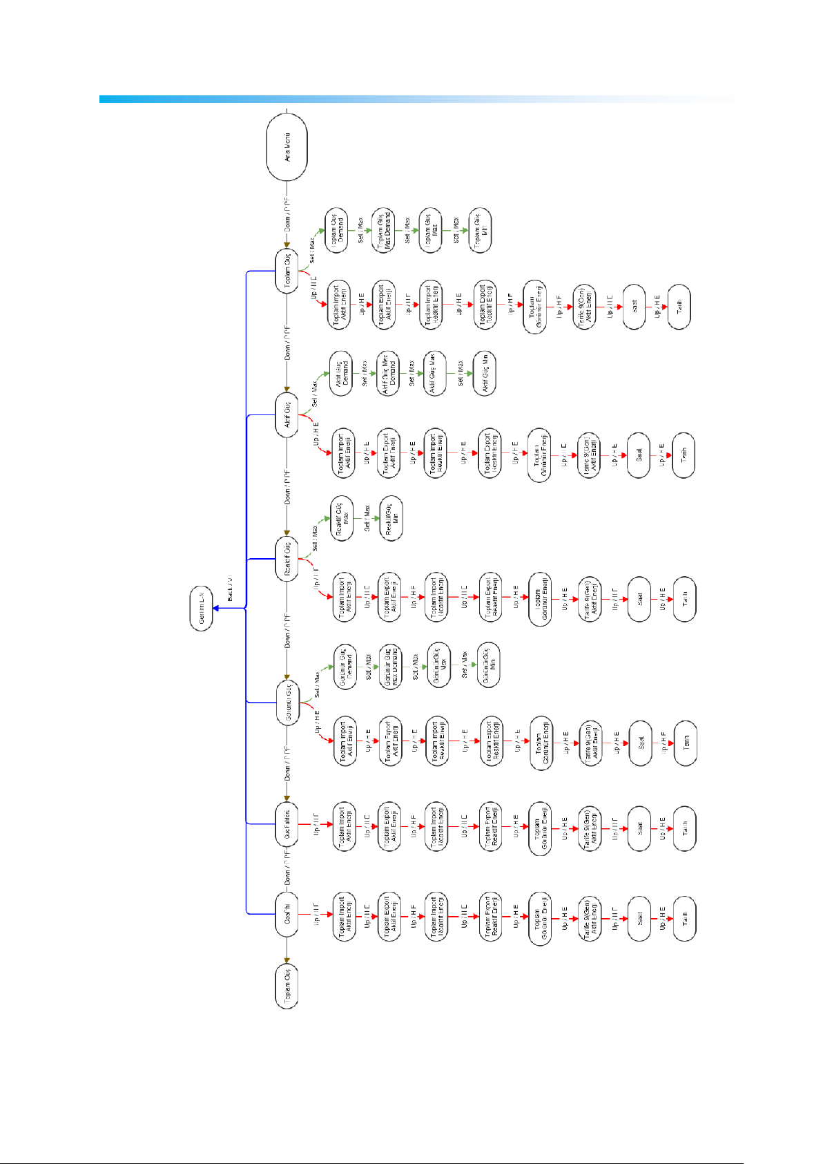
Program Menu Map
61
 Loading...