

Page 1
Cihaz ile aþaðýdaki ölçüm ve uygulamalarý yapabilirsiniz.
1)3 Fazlý bir sistemde Faz Akýmlarý (IL), Nötr / Toplam Akýmý (I
N / SA
); Faz-
Faz ve Faz-Nötr gerilimleri ölçülebilir.
2)Fazlarýn varlýðý cihazýn üst tarafýndaki L1, L2, L3 ýþýklarýyla gözlemlenebilir.
3)Ölçülen akýmlarýn ve gerilimlerin ulaþtýðý min. ve max deðerleri tek tuþla
görülebilir.
4)Ölçülen akýmlara ait max. Demandlar izlenebilir, dt (demand time)
menüsünden max. demand hesaplanma süresi belirlenebilir.
5)Pýn menüsünden 4 haneli bir kullanýcý þifresi belirlenerek, cihazýn ayarlarýný
yetkisiz kiþilerce deðiþtirilmesi önlenebilir.
6)Akým trafosu çeviri oraný deðiþtirilebilir (1 .... 2000).
CT-25li modellerde akým trafosu için tur sayýsý girilebilir (1 ..... 20).
Gerilim trafosu çeviri oraný deðiþtirilebilir (0.1 ..... 4000).
7)Kullanýcý tarafýndan çalýþma zamaný resetlenerek cihazýn elektriksel olarak
ne kadar süre çalýþtýðý saat cinsinden tespit edilebilir.
Tuþlara ait özel fonksiyonlar:
Cihaz ölçme konumundayken (herhangi bir menüye girilmemiþken) aþaðýdaki
tuþ ve tuþ gruplarý bazý özel fonksiyonlarý gerçekleþtirir.
: Program modunda iken bir önceki menüye geçmek, ayarlarý
kaydetmeden program modundan çýkmak için kullanýlýr.
Цlзme modunda parametreler arasэnda geзiюi saрlar. Cihaz
gцstergelerinde faz akэmlarэnэ (A эюэрэ yanarken) veya faz gerilimlerini
(V эюэрэ yanarken) gцsterir.
Program modunda menь ayar deрerlerini ve parametrelerini
deрiюtirmekte kullanэlэr.
ESC
Cihazýn devreye alýnmasý ve menü ayarlarý:
Cihazýn baðlantýlarýný kullanma talimatýnda verilen baðlantý þekillerine uygun
olarak yaptýktan sonra enerji verin.
Ölçüm ve uygulamalarýnýzýn doðru olmasý için menüleri kullanarak gerekli
ayarlamalarý yapýn.
Akým trafosu çeviri oranýnýn girilmesi:
Akým trafosu çeviri oranýnýn girildiði menüdür. 1 ...... 2000 arasýnda
bir deðer girilebilir. (Bu menü CT-25li modellerde yoktur)
Not: Akýmý ölçülen sistem ile cihaz arasýnda akým trafosu
kullanýlmýyorsa, akým trafosu çeviri oranýný 1 giriniz.
Örnek: Akýmý ölçülen sistem ile cihaz arasýnda 30 A / 5 A lýk bir
akým trafosu kullanýlýyorsa;
Akým trafosu çeviri oraný = 30/5
= 6 girilmelidir.
SET
: Min. Anlýk Akýmlar, Gerilimler; Max. Anlýk Akýmlar, Gerilimler ve Max.
Demandlarýn görüntülenmesini saðlar.
3 sn. basýlý tutulduðunda program
moduna geçiþi saðlar. Program modunda; menüye girmek ve
parametredeki deðiþiklikleri kaydetmek için kullanýlýr.
SET
SET
ESC
SET
SET tuþuna basýn trA Fo Ctr
(CT-25li modeller için trA Fo trn)
menüsü görünecektir. (Not:
YUKARI / AÞAÐI tuþlarýný kullanarak
trA Fo Utr veya Con nEC týo n
menüleri görüntülenebilir.)
SET tuþuna basýn. Displayde görünen sayý deðerinin ilk hanesinin yanýp söndüðü
görünecektir. (trA Fo Utr veya Con nEC týo n
menüleride benzer þekilde ayarlanýr.)
YUKARI-AÞAÐI tuþlarýný kullanarak yanýp
sönen hane deðerini ayarlayýn. SET tuþunu
kullanarak sýrayla diðer hanelere geçin, bir
önceki haneye dönmek için ESC tuþunu
kullanýn. Son haneyi ayarladýktan sonra SET
tuþuna basýn, displayde trA Fo Ctr
görünecektir. (Veri girilmiþtir. Fakat henüz
iþleme alýnmamýþtýr. Yeni verinin iþleme
alýnmasý için aþaðýdaki yolu takip edin)
SET
SET tuþuna 3 sn. basýn
(trA Fo menüsü görünecektir.)
SET
Displaylerde (SAU SEt yES) görününceye kadar ESC tuþuna tek tek basýn.
Displaylerde (SAU SEt yES) göründüðünde SET tuþuna basýn
(SAU SEt yES göründüðünde ESC tuþuna basarsanýz veya yES yerine
YUKARI/AÞAÐI tuþlarýný kullanarak no seçeneðini seçerseniz yeni veri
iptal edilecek, bir önceki deðer iþleme alýnacaktýr).
1
MULTÝMETRE
EPM-04h
1 .......
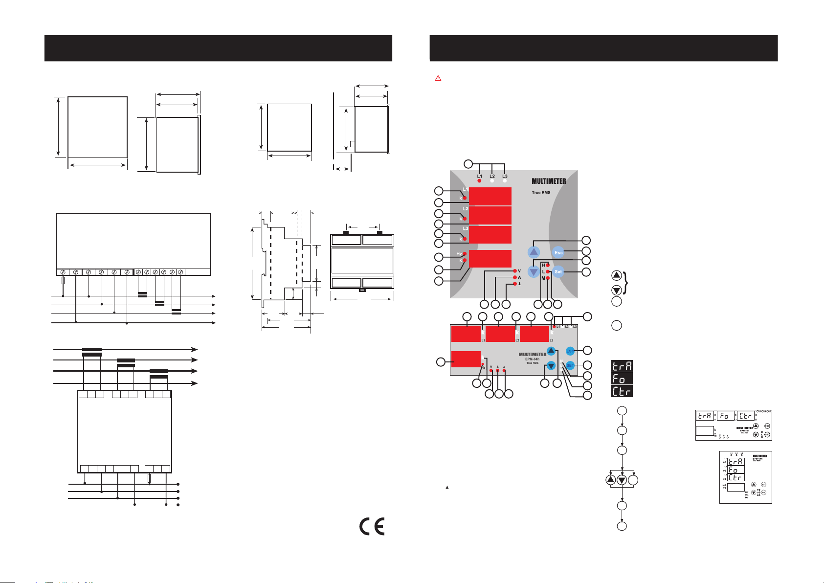
Faz varlýðýný gösteren ýþýklardýr. Cihazýn gerilim giriþlerinden herhangi birine
30 V gerilim geldiðinde bu faza ait ýþýk yanar.
2 .......
1. Displayin (L1 giriюine ait) k эюэрэdэr. k эюэрэ yandэрэnda цlзьlen parametre
deрeri kilo cinsindendir. Цrn: kA, kV gibi.
3 .......
L1 giriþine ait display.
4 .......
2. Displayin (L2 giriюine ait) k эюэрэdэr. k эюэрэ yandэрэnda цlзьlen parametre
deрeri kilo cinsindendir. Цrn: kA, kV gibi.
5 .......
L2 giriþine ait display.
6 .......
3. Displayin (L3 giriюine ait) k эюэрэdэr. k эюэрэ yandэрэnda цlзьlen parametre
deрeri kilo cinsindendir. Цrn: kA, kV gibi.
7 .......
L3 giriþine ait display.
8 ....... Hz эюэрэ yandэрэnda displayde юebeke frekansэnэ gцsterir.
9 ....... Nötr / S akэma ait k эюэрэdэr
. k эюэрэ yandэрэnda цlзьlen parametre deрeri kilo
cinsindendir.
10 ....... Nötr / S akýma ve frekansa ait display.
11 ....... V эюэрэ yanarken L1, L2, L3 displaylerinde gerilim deрerlerini, 4. displayde
frekansý gösterir.
12 ....... A эюэрэ yanarken L1, L2, L3 displaylerinde akэm deрerlerini, 4. displayde nцtr
akýmýný gösterir.
13 .......
эюэрэ yanarken baрlantэnэn delta seзildiрini ifade eder.
14 .......
Max. Anlэk Akэm ve Gerilim (H) эюэрэdэr. Bu эюэk yanarken displaylerde sistemin
Anlэk Max. Akэmlarэ veya Gerilimleri gцsterilir.
15 .......
Min. Anlэk Akэm ve Gerilim (L) эюэрэdэr. Bu эюэk yanarken displaylerde sistemin
Anlэk Min. Akэmlarэ ve Gerilimleri gцsterilir.
16 ....... Max.
Demand (M) эюэрэdэr. Bu эюэk yanarken displaylerde Max. Demandlar
gösterilir.
17 .......
SET tuþu. Ölçme konumundayken 3sn. basýlý tutulursa menüye girilir. Ölçme
konumundayken Max. (H), Min.(L) akým deðerleri ve Max. Demandlarýn izlenmesi
için kullanýlýr.
18 ....... Aþaðý yönde hareket tuþudur.
19 ....... Yukarý yönde hareket tuþudur.
20 .......
ESC tuþu. Menülerden çýkýþ tuþudur.
Genel Bilgi ve Kullaným Alanlarý
Cihaz 3 Fazlý bir sistemde; sistemin Faz Akýmlarýný, Nötr / Toplam Akýmýný, Frekansý
ve Gerilimlerini (Faz-Faz ve Faz-Nötr) ölçmek için tasarlanmýþtýr.
Cihazýn çalýþma süresini gösteren 2 zaman sayacý vardýr. Bunlardan bir tanesi
toplam çalýþma zamanýný gösterirken diðeri çalýþma zamanýný gösterir.
Doðru Kullaným ve Güvenlik Þartlarý:
Cihazýn CT-25li modellerinde mutlaka akým giriþlerine
yapýlacak baðlantý CT-25 Akým Trafosu kullanýlarak yapýlmalýdýr.
Aþaðýdaki þartlara uyulmamasý halinde ölüm ve ciddi yaralanmalar olabilir.
- Cihaz sadece pano tipi montaj içindir.
- Kullanýlacak sigorta F tipi olmalý ve akým sýnýr deðeri 1A olmalýdýr.
- Cihazýn baðlantýlarý yapýlýrken bütün enerjiyi kesiniz.
- Cihaza enerji vermeden önce baðlantýlarý kontrol ediniz.
- Cihaz þebekeye baðlandýðýnda ön paneli çýkartmayýnýz.
- Cihazý solvent yada benzeri bir madde ile temizlemeye çalýþmayýnýz.
Sadece kuru bez kullanýnýz.
- Cihazda meydana gelen arýzalar için yetkili servise baþvurunuz. Cihaza
yetkisiz kiþilerce yapýlan müdahale sonucu ciddi yaralanmalar ve zararlar
meydana gelebilir.
- Bu þartlarýn dikkate alýnmamasý durumunda ortaya çýkacak
sonuçlardan üretici firma yada yetkili satýcýsý sorumlu deðildir.
Toplam Saat (Total Hours)
Cihazýn ilk çalýþmaya baþladýðý andan itibaren çalýþma süresini gösterir. Bu
sayacý kullanýcý sýfýrlayamaz.
Çalýþma Saati (Run Hours)
Cihazýn çalýþma süresini gösterir. Toplam saatten farklý olarak bu saat
sýfýrlanabilir.
Not: Toplam saat ve çalýþma saati cihazýn beslemesi kesildiðinde saymayý
durdurur. Toplam saat ve çalýþma saati süreleri hafýzaya kaydedilir, elektrik
kesilmelerinden etkilenmez. Ölçme modundayken YUKARI/AÞAÐI tuþlarý
kullanýlarak saat gösterimlerine ulaþýlýr. tot -H xxx xx.x (toplam saat) ve rUn H xxx xx.x (çalýþma saati) (x=Saat) þeklinde gösterilir. Displayde gösterilen
deðerlerin hepsi saat cinsindendir. Örneðin; displayde 000 01.7 deðeri
gözüküyorsa cihaz 1.7 saat çalýþmýþ anlamýna gelir. Kullanýcý noktadan sonraki
haneyi dakikaya çevirmek isterse son hane deðeri x 6 formülü ile çevrimi
yapabilir (7x6=42 dk). Cihaz 1 saat 42 dakika çalýþmýþtýr.
2
3
4
5
6
7
8
9
10
11 12 13
17
1614
20
18
19
15
1
EPM-04h
12 4 63 5 7
8 9
10
20
17
18 19
15
14
16
11 12 13
MULTIMETER
EPM-04h
8
A3866 / Rev.2
Dimension
Connection Diagram
Panel Cut-out
92mm
92mm
Type PR 19 (96x96)
70mm
Wall
79.3mm
90mm
Tip 19
50mm
70mm
79.3mm
90mm
Type PR 19 (96x96)
96mm
96mm
Note: For CT-25 models:
PR-19
k
l
K L
k
l
K L
k
l
K L
I
L1
I
L2
I
L3
System
N
L1
L2
L3
1 A
L1
L2
L3
N
Current Measurement Inputs
Auxiliary
Supply
1 2 3 4 5
6
11 127 8 9 10
Voltage Measurement Inputs
PK-26
~
U
n
IL3IL2I
L1
k
l
K L
k
l
K L
k
l
K L
L1 L2 L3 N
N
L1
L2
L3
1
A
Current Measurement
Inputs
Auxiliary
Supply
Voltage Measurement
Inputs
60.6
106.0
10.8
30.1 7.6 9.5
26.5 21.5
53.0
58.0
10.0
8.5
14.0
45.0
90.0
Type PK 26
Turn the current transformer connect,on according to arrow
direction on the transformer
k: When CT-25 is used, Red cable is connected to k terminal.
l: When CT-25 is used, Black cable is connected to l terminal.
System
Page 2
YUKARI-AÞAÐI-SET tuþlarýný kullanarak
yeni þifreyi girin.
YUKARI-AÞAÐI-SET tuþlarýný kullanarak
yeni þifreyi tekrar girin.
Displaylerde (SAU SEt yES) görününceye kadar ESC tuþuna tek
tek basýn.
Displaylerde (SAU SEt yES) göründüðünde SET tuþuna basýn
(SAU SEt yES göründüðünde ESC tuþuna basarsanýz veya yES
yerine no seçeneðini seçerseniz yeni veri iptal edilecek, bir
önceki deðer iþleme alýnacaktýr.)
SET
SET
SET
ESC
SET
YUKARI-AÞAÐI-SET tuþlarýný kullanarak
eski þifreyi girin.
SET
SET tuþuna basýn, Pýn CHA n9E görünecektir (Veri girilmiþtir fakat
henüz iþleme alýnmamýþtýr. Yeni verinin iþleme alýnmasý için
aþaðýdaki yolu takip edin).
Min., max., max. demand ve çalýþma saati deðerlerinin silindiði
menüdür.
Cihazýn parametrelerine ait anlýk olarak ölçülen min., max., max.
demand ve çalýþma saati deðerlerini hafýzasýnda tutar. Min ve
max. deðerleri görebilmek için bu talimatýn tuþlara ait
fonksiyonlar bölümüne bakýnýz.
Not: Hafýzada kaydedilen bilgiler elektrik kesilmelerinden
etkilenmez. rES Et HL, rES Et dE veya rES Et HoU r menüsünde;
yES seçip, tüm menülerden çýkýldýðýnda yapýlan deðiþikliklere
onay verirseniz tüm parametrelere ait min., max. deðerler, max.
demand deðerleri ve çalýþma saati ayný anda silinecektir.
SET tuþuna 3 sn. basýn
(trA Fo menüsü görünecektir.)
SET tuþuna basýn (rES Et HL menüsü görünecektir.)
SET tuþuna basýn rES Et dE / rES Et HL / rES Et Hou r görünecektir
(Seçenek girilmiþtir. Fakat henüz iþleme alýnmamýþtýr. Yeni verinin iþleme
alýnmasý için aþaðýdaki yolu takip edin).
YUKARI-AÞAÐI tuþlarýný kullanarak min.,
max.,demand deðerlerini ve çalýþma saatini
sýfýrlamak istiyorsanýz yES, istemiyorsanýz no
seçin.
SET
SET
SET
YUKARI-AÞAÐI tuþlarýný kullanarak
rES Et dE / rES Et HL/rES Et HoU r
menüsünü bulun
SET tuþuna basýn (rES Et dE no /
rES Et HL no / rES Et HoU no görünecektir.)
SET
Displaylerde (SAU SEt yES) görününceye kadar ESC tuþuna tek tek
basýn.
Displaylerde (SAU SEt yES) göründüðünde SET tuþuna basýn (SAU SEt
yES göründüðünde ESC tuþuna basarsanýz veya yES yerine no
seçeneðini seçerseniz yeni seçenek iptal edilecek, bir önceki seçenek
iþleme alýnacaktýr.)
SET
ESC
Kullanýcý þifresinin tanýmlanmasý:
Kullanýcý þifresinin tanýmlandýðý ve aktif yapýldýðý menüdür. Cihazýn ayarlarýnýn
yetkisiz kiþilerce deðiþtirilmesini önlemek için, bu menüde 4 haneli bir
kullanýcý þifresi belirleyip bu þifreyi aktif hale getirmelisiniz.
Pýn menüsünün altýnda 2 adet alt menü vardýr.
ESC
SET
Displaylerde (SAU SEt yES) görününceye kadar ESC tuþuna tek tek basýn.
Displaylerde (SAU SEt yES) göründüðünde SET tuþuna basýn (SAU SEt
yES göründüðünde ESC tuþuna basarsanýz veya yES yerine no
seçeneðini seçerseniz yeni ayarlar kaydedilmeden ayar menüsünden
çýkýlýr. Cihaz önceki ayarlarýyla çalýþmaya devam eder.)
Kullanýcý þifresini aktif hale getirmek için kullanýlan menüdür.
Kullanýcý þifresi aktif hale getirildiði takdirde program moduna
geçmek için; tuþuna 3 sn. basýldýðýnda kullanýcý þifresi
sorulacaktýr. Kullanýcý þifresi yanlýþ girilirse cihaz kilitlenmez.
Not: Fabrika çýkýþý kullanýcý þifresi 0000 dýr.
Kullanýcý þifresinin aktif hale getirilmesi:
SET tuþuna 3 sn. basýn (trA Fo menüsü görünecektir.)
YUKARI-AÞAÐI tuþlarýný
kullanarak Pýn menüsünü bulun
SET tuþuna basýn (Pýn ACt IUA tE menüsü görünecektir.)
Kullanýcý þifresini aktif hale getirmek için; Ölçme konumundayken,
SET
SET
SET
SET
2
MULTÝMETRE
EPM-04h
Gerilim trafosu çeviri oranýnýn girilmesi:
Gerilim trafosu çeviri oranýnýn girildiði menüdür.
Bu deðer 0000,1 - 4000,0 arasýnda ayarlanabilir.
Not: Gerilimi ölçülen sistem ile cihaz arasýnda gerilim trafosu
kullanýlmýyorsa, gerilim trafosu çeviri oranýný 1 giriniz.
Örnek: Gerilimi ölçülen sistem ile cihaz arasýnda 34,5KV/100V luk
bir gerilim trafosu kullanýlýyorsa;
Gerilim trafosu çeviri oranýný = 34500/100
= 345 girilmelidir.
Baðlantý þeklinin seçilmesi:
Baðlantýnýn Star yada Delta baðlantý olarak seçildiði menüdür.
Star baðlantý seçildiðinde; cihaz 3 faz 4 hat (3P4W) baðlantý
ile çalýþýr. 4. displayde Nötr akýmý gösterilir.
Delta baðlantý seçildiðinde; cihaz 3 faz (3P3W) baðlantý ile çalýþýr
ve Delta эюэрэ yanar. 4. displayde Nцtr akэm yerine toplam akэm
gösterilir.
SET tuþuna basýn. Displayde görünen sayý deðerinin ilk hanesinin yanýp
söndüðü görünecektir.
YUKARI-AÞAÐI tuþlarýný kullanarak yanýp
sönen hane deðerini ayarlayýn. SET tuþunu
kullanarak sýrayla diðer hanelere geçin, bir
önceki haneye dönmek için ESC tuþunu
kullanýn. Son haneyi ayarladýktan sonra SET
tuþuna basýn, displayde Pýn ACt oF
görünecektir.
YUKARI-AÞAÐI tuþlarýný
kullanarak on seçilebilir.
(Veri girilmiþtir.
Fakat henüz iþleme alýnmamýþtýr. Yeni verinin
iþleme alýnmasý için aþaðýdaki yolu takip
edin)
SET
Tur sayýsýnýn girilmesi:
Bu menü CT-25li modellerde vardýr.
Ct-25 akým trafosunun içinden,
ölçülen hat kablosunun kaç kez geçirildiði, yani tur sayýsý seçilir.
1 ile 20 arasýnda deðer girilebilir. Tur sayýsý artma oranýnda ölçme
hassasiyeti artar.
1
2.00
120
2
1.00
60.0
3
0.66
40.0
4
0.50
30.0
5
0.40
24.0
6
0.33
20.0
7
0.28
17.1
8
0.24
15.0
9
0.22
13.3
10
0.20
12.0
11
0.18
10.9
12
0.16
10.0
13
0.15
9.23
14
0.14
8.57
15
0.13
8.00
16
0.12
7.50
17
0.11
7.05
18
0.11
6.66
19
0.10
6.31
20
0.10
6.00
SET tuþuna 3 sn. basýn
(trA Fo menüsü görünecektir.)
YUKARI-AÞAÐI tuþlarýný
kullanarak Pýn menüsünü bulun
SET tuþuna basýn (Pýn ACt IUA tE menüsü görünecektir.)
SET
SET
YUKARI-AÞAÐI tuþlarýný kullanarak Pýn CHA n9E menüsünü
bulun
Kullanýcý þifresinin deðiþtirilmesi:
Kullanýcý þifresini deðiþtirmek için kullanýlan menüdür.
Not: Fabrika çýkýþý kullanýcý þifresi 0000 dýr.
YUKARI-AÞAÐI tuþlarýný
kullanarak rES Et menüsünü bulun
MULTIMETER
EPM-04h
7
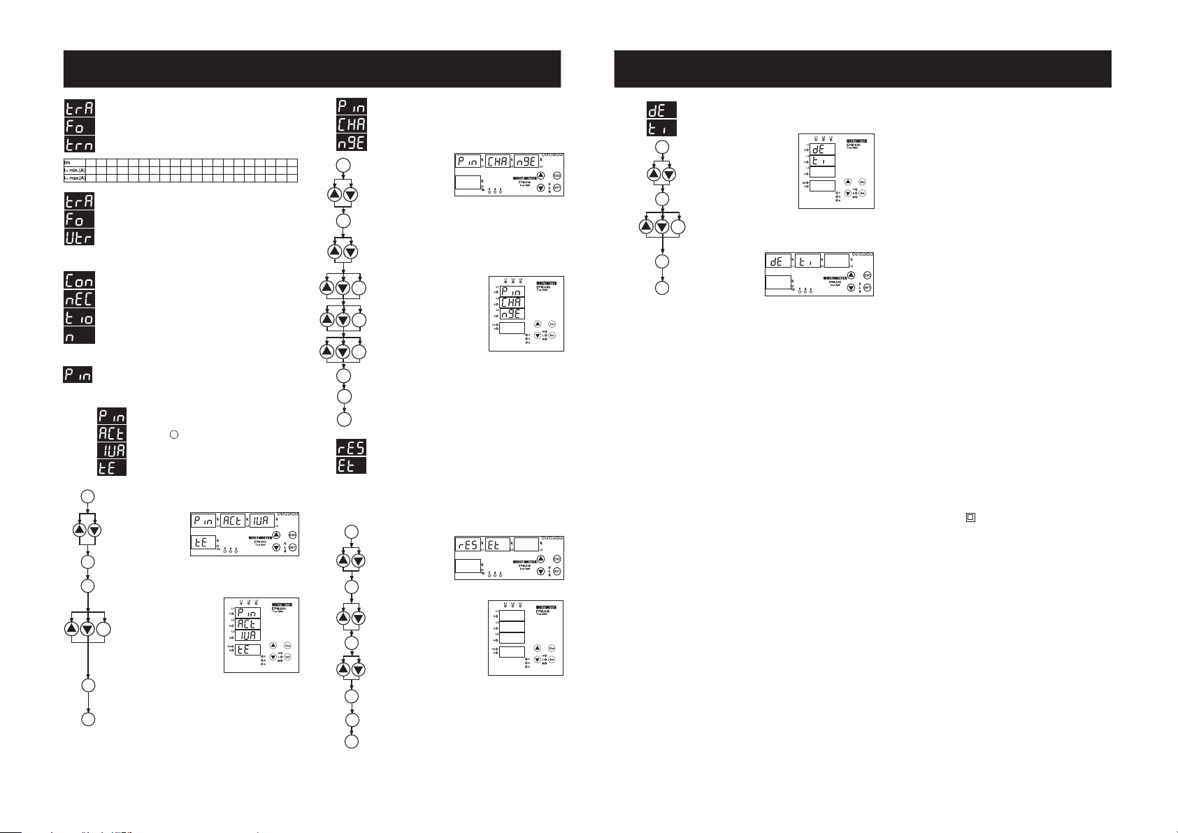
Max. Demand time can be defined between 0160 minute in this menu.
Press SET button for 3 sec.
(trA Fo menu is displayed.)
Find
dE tý
menu by scrolling UP-DOWN
buttons.
Press SET button. Blinking the first digit of
displayed value appears.
SET
SET
Enter the blinking digit value by scrolling UP/DOWN buttons. Switch
to the other digits by using SET button, use ESC button to go to
previous digit. After you entered the last digit press SET button, dE
tý is displayed.
(Data is entered but is not activated yet. For activating
the new data please follow the below steps).
SET
Press ESC button one by
one until SAU E SEt
yES is displayed.
ESC
SET
Press SET button. When
SAU E SEt yES is
displayed (If you press
ESC button or choose
no option instead of yES then new data will be cancelled and
previous value will be activated).
Factory Settings
Ctr - 0001
Utr - 0001
trn - 01
ConnEC - StAr
Pin Act - oF
Pin - 0000
dt - 15
Technical Features
Rated Voltage (Un) : Please look at back side of the device.
Operating Frequency (f) : 45-65 Hz
Auxiliary Supply Power Consumption : < 4 VA
Measuring Input Power Consumption : < 1 VA
Measurement Range
Current : 0.05-5.5A~
: 2 - 120 A~ for CT-25
Voltage : 10-300 V AC (Phase-Neutral)
10-500 V AC (Phase-Phase)
Class : 1±1% digit [(10%-100%) x full scale]
Current Transformer Ratio : 1 ... 2000
Turn number for CT-25 adapted models: 1 .... 20
Voltage Transformer Ratio : 1 ... 4000
Max. Ctr x Vtr : 40.000
Ambiant emperature : -5°C; +50°C
Display : Red LED display
Dimensions : PR-19, PK-26
Equipment Protection Class : Double Insulation - Class II (
)
Box Protection Class : IP 40
Terminal Protection Class : IP 00
Box Material : Nonflamable
Mounting : Panel Mounted (PR-19)
Rail Mounted (PK-26)
Wire Thickness for Terminal Block : 2.5 mm
2
Weight :
0.45 kg (PR-19, PK-26)
Mounting Category : Class III
Panel Size : 91x91 mm (PR-19)
46x107 mm (PK-26)
Page 3

MULTÝMETRE
EPM-04h
3
Max. Demand süresinin ayarlandýðý menüdür.
01 - 60 dakika ayarlanabilir.
SET tuþuna 3 sn. basýn
(trA Fo menüsü görünecektir.)
YUKARI-AÞAÐI tuþlarýný
kullanarak dE tý menüsünü bulun
SET tuþuna basýn. Displayde görünen sayý
deðerinin ilk hanesinin yanýp söndüðü görünecektir.
SET
SET
YUKARI-AÞAÐI tuþlarýný kullanarak yanýp sönen hane deðerini ayarlayýn.
SET tuþunu kullanarak sýrayla diðer hanelere geçin, bir önceki haneye
dönmek için ESC tuþunu kullanýn. Son haneyi ayarladýktan sonra SET
tuþuna basýn, displayde dE tý görünecektir. (Veri girilmiþtir. Fakat henüz
iþleme alýnmamýþtýr. Yeni verinin iþleme alýnmasý için aþaðýdaki yolu takip
edin)
SET
Displaylerde (SAU SEt yES)
görününceye kadar ESC
tuþuna tek tek basýn.
ESC
SET
Displaylerde (SAU SEt yES)
göründüðünde SET tuþuna
basýn (SAU SEt yES
göründüðünde ESC tuþuna
basarsanýz veya yES yerine no seçeneðini seçerseniz yeni ayarlar
kaydedilmeden ayar menüsünden çýkýlýr. Cihaz önceki ayarlarýyla çalýþmaya
devam eder.
Teknik Özellikler
Ýþletme Gerilimi (Un) : Lütfen cihazýn arkasýna bakýnýz.
Ýþletme Frekansý (f) : 45-65 Hz
Besleme Giriþi Güç Tüketimi : < 4 VA
Ölçme Giriþi Güç Tüketimi : < 1 VA
Ölçme Aralýðý
Akým : 0.05-5.5A~
: CT-25 için 2 - 120 A~
Gerilim : 10-300 V AC (Faz-Nötr)
10-500 V AC (Faz-Faz)
Sýnýf : %1±1dijit [(%10-%100) x tam skala]
Akým Trafosu Oraný : 1 ... 2000
CT-25li modeller için tur sayýsý : 1 .... 20
Gerilim Trafosu Oraný : 1 ... 4000
Max. Ctr x Vtr : 40.000
Ortam Sýcaklýðý : -5°C; +50°C
Gösterge : Kýrmýzý LED display
Boyutlar : PR-19, PK-26
Cihaz Koruma Sýnýfý : Çift Yalýtým - Sýnýf II (
)
Kutu Koruma Sýnýfý : IP 40
Terminal Koruma Sýnýfý
: IP 00
Kutu Malzemesi : Yanmaz
Baðlantý Þekli : Panoya Önden (PR-19)
Klemens Rayýna (PK-26)
Terminal Baðlantýsý için Kablo Kalýnlýðý : 2.5 mm
2
Aðýrlýk :
0.45 kg (PR-19, PK-26)
Montaj Sýnýfý : Sýnýf III
Pano Delik Ölçüleri : 91x91 mm (PR-19)
46x107 mm (PK-26)
Fabrika Çýkýþ Deðerleri
Ctr - 0001
Utr - 0001
trn - 01
ConnEC - StAr
Pin Act - oF
Pin - 0000
dt - 15
Enter the new password by scrolling
UP/DOWN/SET buttons.
Enter the new password again by
scrolling UP/DOWN/SET buttons.
Press ESC button one by one until SAU E SEt yES is displayed.
Press SET button. When SAU E SEt yES is displayed (If you press
ESC button or choose no option instead of yES then new data
will be cancelled and previous value will be activated).
SET
SET
SET
ESC
SET
Enter the old password by scrolling
UP/DOWN/SET buttons.
SET
Press SET button, Pýn CHA n9E is displayed.
(Data is entered but is not activated yet. For activating the new data
please follow the below steps)
In this menu, values of min., max., max. demand and run hour
values are erased. It saves the instantaneously measured min.
and max. values of the device into its memory. Please kindly look
at to the section of FUNCTIONS OF BUTTONS for min. and max.
values.
Note:
Measured electrical parameters which are saved to the
memory are not affected from the electric interruptions.
In the rES Et HL, rES Et dE or rES Et HoU r menu; when you
choose yES and quit from all menus, if you confirm the changes,
min., max. and max. demand values of all parameters are erased
at the same time.
Press SET button for 3 sec. (trA Fo menu is displayed.)
Press SET button (rES Et HL menu is displayed.)
Press SET button, rES Et dE / rES Et HL / rES Et Hou r is displayed.
(Data
is entered but is not activated yet. Activating the new data, please
follow the below steps)
By using the UP-DOWN buttons, other
parameters can be selected. If you want to
delete the max. demand values and run hour
choose yES, if not choose no.
SET
SET
SET
Find
rES Et dE / rES Et HL/rES Et HoU r
menu by scrolling UP-DOWN buttons.
Press SET button (rES Et dE no / rES Et HL
no / rES Et HoU no is displayed.)
SET
Press ESC button one by one until SAU E SEt yES is displayed.
Press SET button. When SAU E SEt yES is displayed (If you press
ESC button or choose no option instead of yES then new data will
be cancelled and previous value will be activated).
SET
ESC
ESC
SET
Press ESC button one by one until SAU E SEt yES is displayed.
Press SET button. When SAU E SEt yES is displayed (If you press
ESC button or choose no option instead of yES then new data will
be cancelled and previous value will be activated).
Press SET button for 3 sec. (trA Fo menu is displayed)
Find the Pýn menu by scrolling
UP/DOWN buttons.
Press SET button (Pýn ACt IUA tE is displayed.)
SET
SET
SET
6
MULTIMETER
EPM-04h
Press SET button. Blinking the first digit of displayed value appears.
Enter the blinking digit value by scrolling
UP/DOWN buttons. Switch to the other
digits by using SET button, use ESC button
to go to previous digit. After you entered
the last digit press SET button,
Pýn ACt oF is displayed.on can be
selected by scrolling UP/DOWN buttons.
(Data is entered but is not activated yet.
For activating the new data please follow
the below steps).
SET
1
2.00
120
2
1.00
60.0
3
0.66
40.0
4
0.50
30.0
5
0.40
24.0
6
0.33
20.0
7
0.28
17.1
8
0.24
15.0
9
0.22
13.3
10
0.20
12.0
11
0.18
10.9
12
0.16
10.0
13
0.15
9.23
14
0.14
8.57
15
0.13
8.00
16
0.12
7.50
17
0.11
7.05
18
0.11
6.66
19
0.10
6.31
20
0.10
6.00
Press SET button 3 sec.
(trA Fo menu is displayed.)
Find the Pýn menu by
scrolling UP/DOWN buttons.
Press SET button (Pýn ACt IUA tE is displayed.)
SET
SET
Find the Pýn CHA n9E menu by scrolling UP/DOWN buttons.
Find
rES Et
menu by scrolling
UP-DOWN buttons.
Programming the Turn Number:
This menu is available for CT-25 adapted devices. User defines the
turn number, which is the number of how many tour the current
cable has rounded into the CT-25. Numbers can be selected
between 1-20. Greater the number of turn means greater the
sensivity.
Voltage Transformer Ratio:
In this menu, voltage transformer ratio is set between 0000,1 - 4000,0.
Note: If the voltage transformer is not used between the system and
device, voltage transformer ratio is entered as 1.
Example: If a voltage transformer which has a ratio of 34.5KV/100V
is used between the system and device; Voltage transformer ratio
is entered as 345. (34500/100)
Selecting the Connection Type :
Connection can be selected as Star or Delta in this menu.
When the Star connection is choosen, device works as 3 Phase
4 Wire (3P4W) connection. Neutral current is shown in 4th display.
When the Delta connection is choosen, device works as 3 phase
(3P3W) connection and delta light flashes. Total current is shown
in 4th display instead of neutral current.
User Password Setup:
In this menu user password is defined and activated.
You must define and activate a 4 digit user password for preventing device
settings from the illegal usage.
There are 2 sub menu in the Pýn menu.
This menu is used for activating the user password.
After the user password is activated for entering to the menus;
if the button is pressed for 3 sec., while the instant values
are observed, user password is required. If the user password
is entered wrong device does not latch.
Note: Factory default value of user password is 0000
Activating the user password :
SET
Changing of User Password:
This menu is used for changing the user password .
Note: Factory default value for user password is 0000
Page 4

SET
SET
ESC
SET
Press SET button; trA Fo Ctr menu
is displayed (In CT-25 adapted
devices, trA Fo trn is displayed
instead.)
(Note: trA Fo Utr or Con nEC týo
n menu can be displayed by
scrolling the UP/DOWN buttons.)
Press SET button. Blinking the first digit of displayed value appears.
(trA Fo Utr or Con nEC týo n menu can be programmed similarly.)
Enter the blinking digit value by scrolling
UP/DOWN buttons. Switch to the other
digits by using SET button, use ESC
button to go to previous digit. After you
entered the last digit press SET button,
trA Fo Ctr is displayed.
(Data is entered
but is not activated yet. For activating the
new data please follow the below steps).
SET
Press SET button for 3 sec.
(trA Fo menu is displayed)
SET
Press ESC button one by one until
SAU E SEt yES is displayed.
Press SET button. When SAU E SEt yES is displayed (If you press
ESC button or choose no option instead of yES then new data will be
cancelled and previous value will be activated).
5
MULTIMETER
EPM-04h
1 .......
Phase LEDs:The LEDs turn on when the voltage value, which is applied
to one of the current inputs, reach 30 V
2 ....... First displays k LED (for L1). Measurement parameter is the unit of kilo
when LED is turned on. ie: kA, kV
3 ....... Display for
L1.
4 ....... Second displays k LED (for L2). Measurement parameter is the unit of kilo
when LED is turned on. ie: kA, kV
5 ....... Display for
L2.
6 ....... Third displays k LED (for L3). Measurement parameter is the unit of kilo
when LED is turned on. ie: kA, kV
7 ....... Display for
L3.
8 ....... Displays network frequency when Hz LED is turned on.
9 ....... k LED for neutral / S current. Measurement parameter is displayed in unit of
kilo when this LED is turned on.
10 ....... Display for neutral / S current and frequency
11 ....... Monitoring the L1, L2, L3 voltages values when V LED is turned on and
displays the frequency in 4th display.
12 ....... Monitoring the L1, L2, L3 currents values when A LED is turned on and
displays the neutral current in 4th display.
13 ....... Indicates the activating delta connection when
is turned on.
14 ....... H LED for max. instant current and voltage. Max. instant currents and
voltages are displayed when this LED is turned on.
15 ....... L LED for min. instant current and voltage. Min. instant currents and
voltages are displayed when this LED is turned on.
16 ....... M LED for max. demand. Max. demand values are displayed when this
LED is turned on.
17 ....... SET button. It is used to enter into the menu and to save the values.
If SET button is pressed for 3 sec. in the measurement mode, you can
enter into menus. This button is used for monitoring the max. (H), Min.
(L) current values and max. demand values in measurement mode.
18 ....... Downward selection button.
19 ....... Upward selection button.
20 .......
ESC button. Escaping from the menu.
Total Hours
It shows the running time from the beginning. The user can not reset total
hours.
Run Hours
It shows the running hour. Differently from total hour, this can be resetted.
Note: Total hour and run hour do not count during electric interruptions. Total
hour and run hour saves to memory and is not affected by electric interruptions.
During measure mode, using up and down buttons, user can see reach running
time. tot -H xxx xx.x (total hour) and rUn -H xxx xx.x (run hour) (x=Hour) are
shown in this forms. All the values are in terms of hour which are shown on the
display.For example 00001.7 value is shown on the display this means that
device worked for 1,7 hours. Ýf the user wants to translate last digit to minutes,user
can multiple last digit by 6. (7x6=42 minutes). Device worked 1 hour and 42
minutes.
PRECAUTIONS FOR INSTALLATION AND SAFE USE
General information
EPM-04h is designed for measuring the below parameters in a
3-Phase system. Phase current, frequency, neutral / total current and voltages
(Phase-Phase and Phase-Neutral).
There are 2 timers which show the running hour. One of them shows run hour,
other shows total hour.
Below measurement and application can be implemented with
EPM-04h.
1)Phase currents (IL), Neutral / total current (IN /
SA
), Phase-Phase and
Phase-Neutral voltages can be measured .
2)
Existence of live phases can be observed by L1-L2-L3 LEDs on the device.
3) Min. and max. values for measured currents and voltages can be monitored
with only one button.
4) Max. demand values for measured current can be monitored, demand
time can be defined in dE tý menu.
5)
A 4 digit password can be defined from pin menu in order to prevent the
change of settings by unauthorized person.
6) Current transformer ratio is programmable. (1 .... 2000)
Current transformer ratio can be programmed in term of turn number
between 1.....20 (for CT-25 adapted devices).
Voltage transformer ratio is programmable. (0.1 .... 4000)
7) Run hour can be resetted and electrical run hour of device can be detected
in terms of hour by the user.
Using the Buttons:
Some buttons and button groups are used for the below special function
when device is in the measurement mode (Without selecting a menu).
: Switching to the previous menu and escaping the programming
menu without saving the changes.
Monitoring for phase currents (A LED is activated) or phase voltages
(V LED is activated).
Used for changing the menu settings and parameters in programming
mode.
ESC
SET
: Used for monitoring min. / max. currents and voltages or max. demand
values. Switching to the programming mode if it pressed for 3 sec. In
programming mode; it is used for switching to the menu and saving
changes for the parameters.
Commissioning the EPM-04h and menu setting:
Energize the device after implementing the connections respected to the
user manual.
Enter the proper menu settings in order to correct measurements and
applications.
Current Transformer Ratio Setup:
In this menu, current transformer ratio is set between 1 - 2000.
(This menu is not available in the devices which are adapted
with CT-25.)
Note: If the current transformer is not used between the system
and device, current transformer ratio is entered as 1.
i.e.: If a current transformer which has a ratio of 30/5A is used
between the system and device;
Current transformer ratio is entered as = 30/5 = 6.
MULTÝMETRE
EPM-04h
4
A3866 / Rev.2
Boyutlar
Baðlantý Þekli
Panel Delik Ölçüleri
92mm
92mm
Tip PR 19 (96x96)
70mm
Duvar
79.3mm
90mm
Tip 19
50mm
70mm
79.3mm
90mm
Tip PR 19 (96x96)
96mm
96mm
Not: CT-25 Akým Trafolu modellerde;
PR-19
k
l
K L
k
l
K L
k
l
K L
I
L1
I
L2
I
L3
Sistem
N
L1
L2
L3
1 A
L1
L2
L3
N
Akým Ölçme Giriþleri
Yardýmcý
Besleme
1 2 3 4 5
6
11 127 8 9 10
Gerilim Ölçme Giriþleri
PK-26
~
U
n
I
L3
IL2I
L1
k
l
K L
k
l
K L
k
l
K L
L1 L2 L3 N
N
L1
L2
L3
1
A
Akým Ölçme
Giriþi
Yardýmcý
Besleme
Gerilim Ölçme
Giriþi
60.6
106.0
10.8
30.1 7.6 9.5
26.5 21.5
53.0
58.0
10.0
8.5
14.0
45.0
90.0
Tip PK 26
Akým trafosu baðlantýsýný trafo üzerindeki ok yönüne dikkat ederek yapýnýz.
k: CT-25 kullanýldýðý zaman kýrmýzý kabloyu k giriþine baðlayýn.
l: CT-25 kullanýldýðý zaman siyah kabloyu l giriþine baðlayýn.
Sistem
In CT-25 (120A) compliant models, only CT-25 current transformer
must be used.
Other type of CTs have a high risk to damage to device.
Failure to follow those instructions will result in death or serious injury.
- Disconnect all power before working on equipment.
- When the device is connected to the network, do not remove the front
panel.
- Do not try to clean the device with solvent or the like.Only clean with dry
cloth.
-Appeal to authorized service for the faults that are occured in the
device interference of unauthorised person can cause serious
injuries and damages.
- Only for rack panel mounting.
- Fuse must be F type and limit value doesnt exceed 1A.
- No responsibility is assured by manufacturer or any of its subsidiaries
for any consequences arising out of the use of this material.
2
3
4
5
6
7
8
9
10
11 12 13
17
1614
20
18
19
15
1
EPM-04h
12 4 63 5 7
8 9
10
20
17
18 19
15
14
16
11 12 13
 Loading...