

Page 1

EMG Ethernet Modbus Gateway
User Manual
Rev 2.2
07/2010
Page 2

CONTENTS
1. Introduction
1.1. General Features
1.2 Installing the Drivers
2. Configuration
2.1 Main Device Parameters
2.1.1 RS485 Serial Communication Parameters
2.1.1.1 Baud Rate
2.1.1.2 Data Bit
2.1.1.3 Stop Bit
2.1.1.4 Parity Bit
2.1.1.5 Time-Out
2.1.1.6 Delay
2.1.2 Network Parameters
2.1.2.1 Connection Settings
2.1.2.2 DHCP
2.1.2.3 WEB Access
2.1.2.4 WEB Port
2.1.2.5 Log-in Timeout
2.1.2.6 Server IP
2.1.2.7 IP Address
2.1.2.8 Subnet Mask
2.1.2.9 Default Gateway
2.1.2.10 MODBUS/TCP Port
2.1.2.11 Link
2.1.3 Operating Modes (MODBUS/TCP /Tunnel Mode)
2.1.3.1 MODBUS/TCP Packet Structure
2.1.3.2 Tunnel Mode Packet Structure
2.1.4 Configuration example for communicating over ADSL modem
2.1 Reading/Changing the Configuration using the USB interface
2.2 Security settings
2.3 Reading/Changing the Configuration using the WEB interface
Page 3

3. Firmware Updates
4. Appendices
Appendix A Differences between EMG model devices
Appendix B Query Interval and TCP Time-Out
Page 4
1.Introduction
1.1 General Features
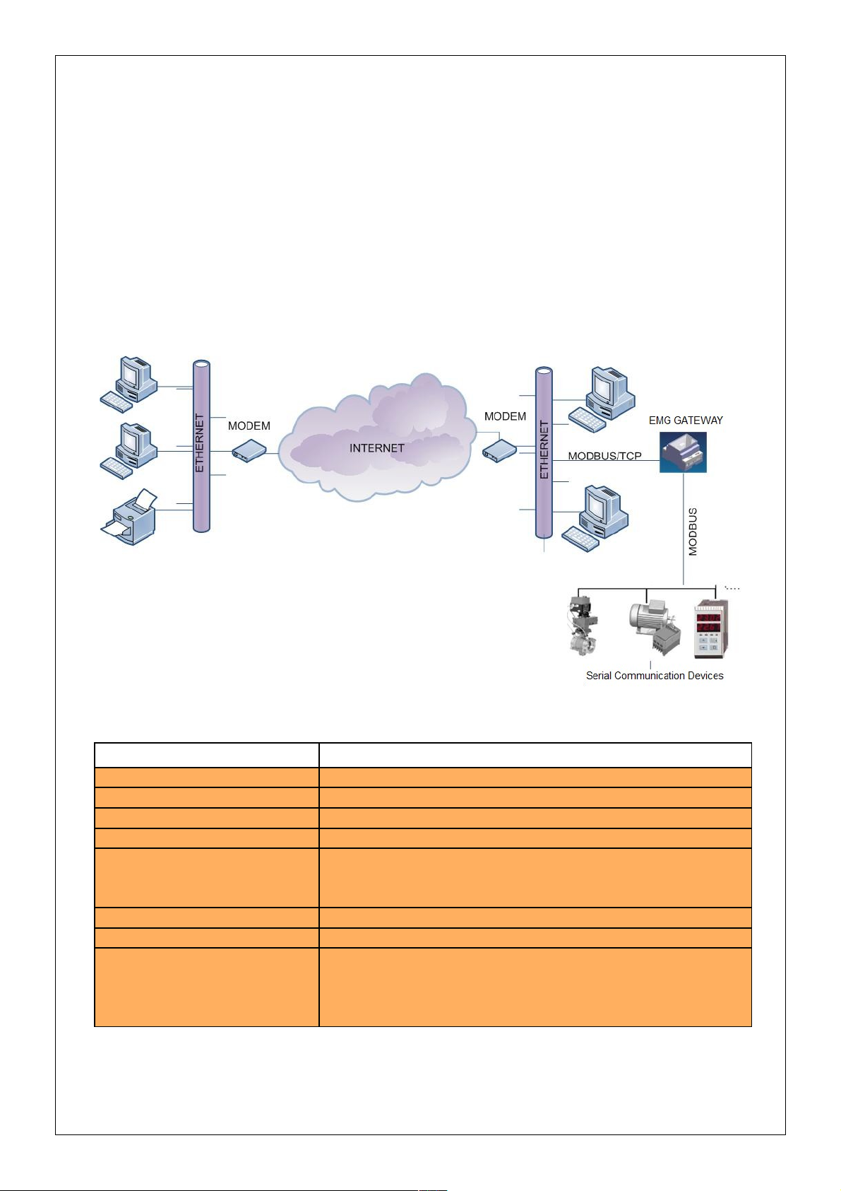
ENTES EMG family series MODBUS Gateway is a MODBUS/TCP protocol converter
that lets the users control their devices remotely through serial connection via the RS-485
protocol using TCP/IP protocol over the existing internet/intranet infrastructure. While it
is possible to monitor from one place with EMG-10, it is possible to monitor from 4
different places with EMG-02 and EMG-12.
Technical Data :
Table 1. EMG Series Technical Data
Category Description
Network Protocols TCP/IP, ARP, ICMP, HTTP, ModbusTCP
Serial Ports RS485 for Communication, USB Port for Configuration
Operating Modes ModbusTCP/RTU and Modbus Tunnel
Network Interface 10/100 Mbps auto-negotiation
Serial Communication
Formats
Serial Interface 300-115200 bps
Power Supply 9-24V AC - 9-30V DC or from USB port(~75 mA)
Insulation and Protection
Data Bits : 5-6-7-8 data bit
Stop Bit: 1-1.5-2 characters
Parity: Even-Odd-None
RS485 port: 500V
Ethernet port: 1500V
15KV ESD protection on USB port
10/1000 us (600W) transient pulse protection on RS485 port
Page 5
1.2 Installing the drivers
Since the EMG series devices communicate through the computer USB port, the drivers
which come with the bundled CD must be installed to the computer before using the
device.
To install the drivers;
1. Connect the EMG series device to the computers through the USB port of
computer. The POWER LED on the device should turn on and the computer will
recognize the device automatically.
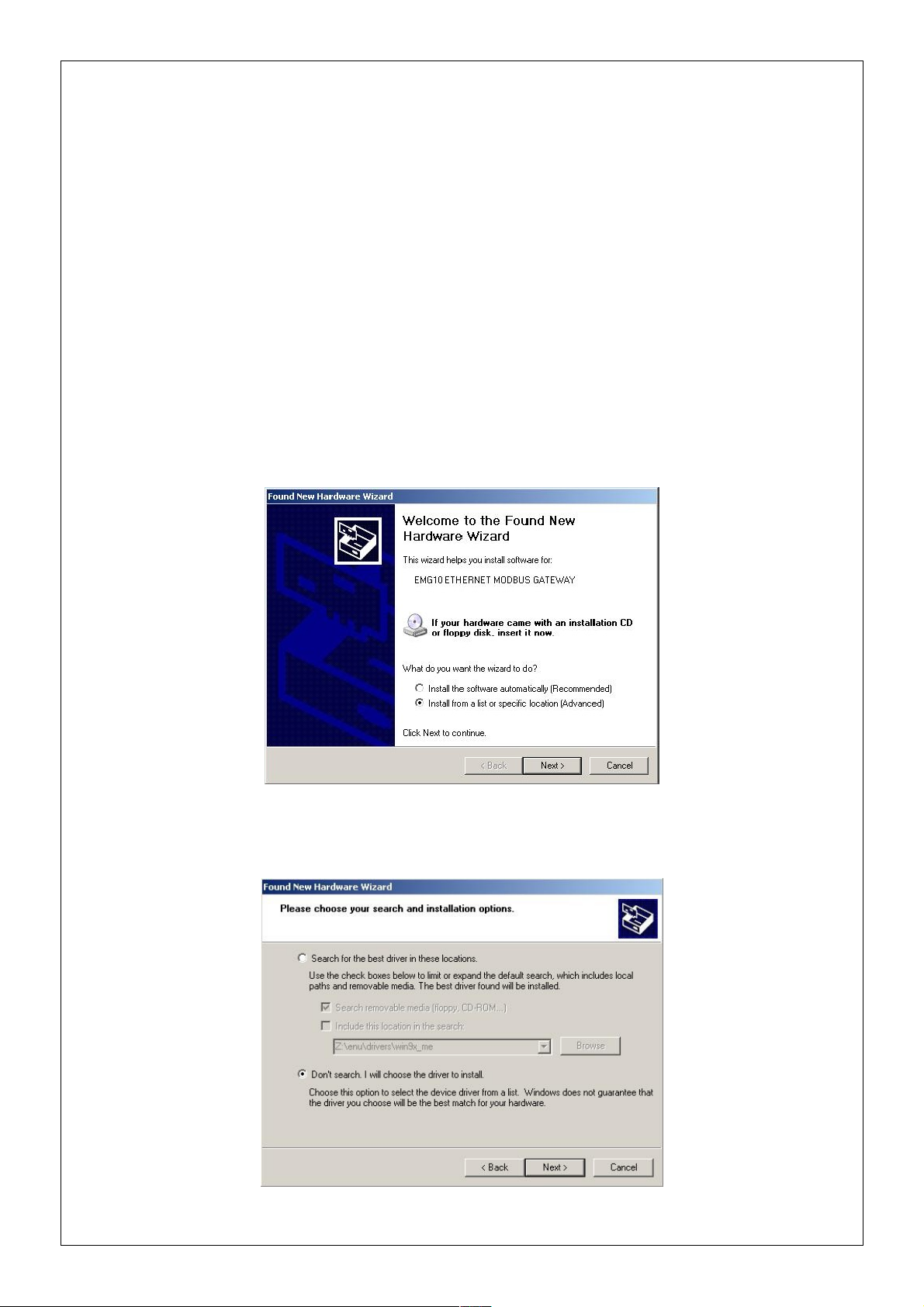
2. To locate the driver files manually, select “Install from a list or specific location”
option and click on “Next”.
3. On the next window, specify the location of the drivers and click on “Next”.
Page 6
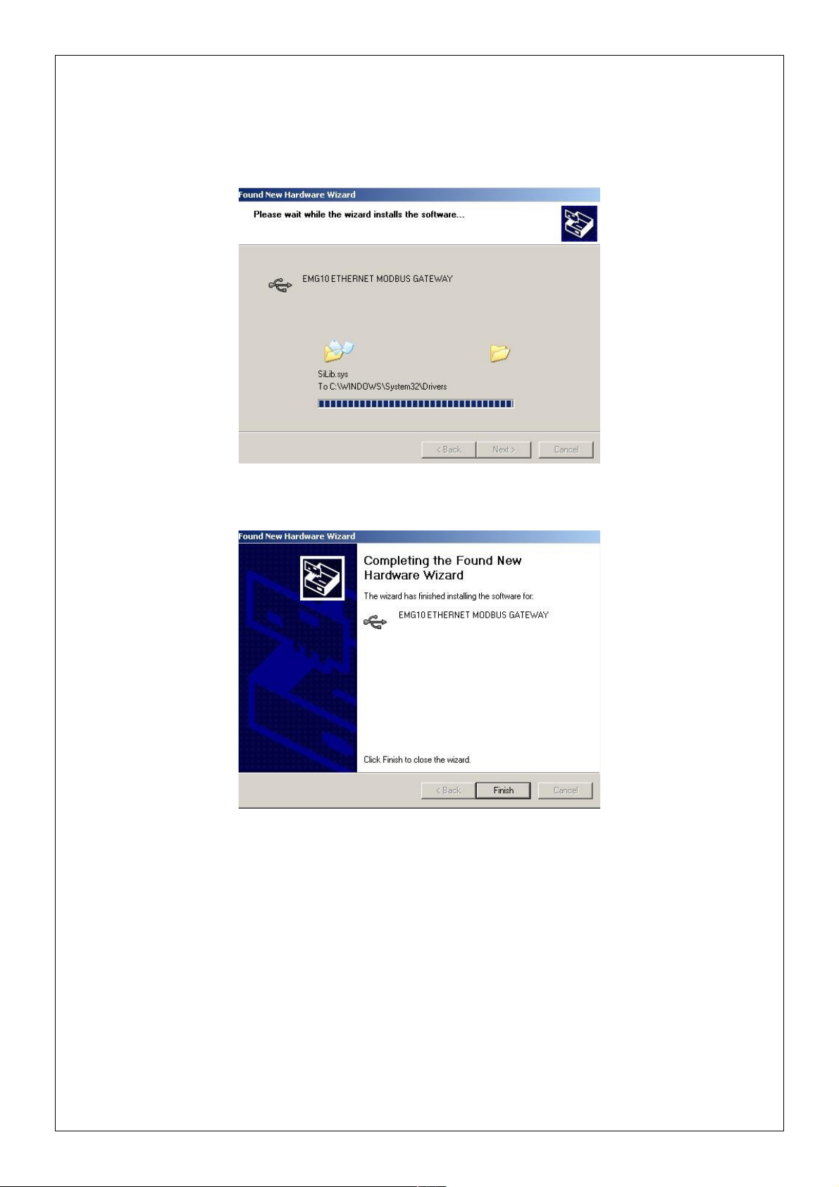
4. Click on “Continue” on the next window
5. The system will copy the necessary files to the computer.
6. Copying progress is finished and the EMG Series device is now ready to use.
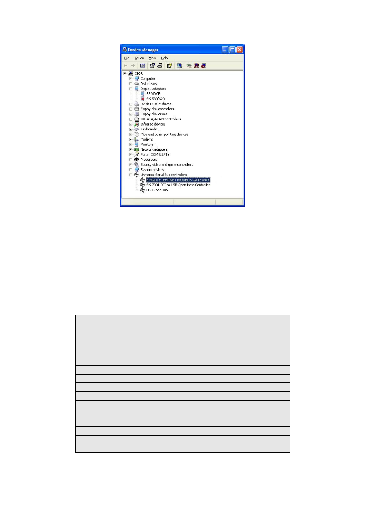
7. After the installation is completed, the device can be seen using these steps:
My Computer → Control Panel → System → Device Manager → Universal
Serial Bus Controller
Page 7
2. Configuration
2.1 Main Device Parameters
In order for the device to function properly, both the RS-485 serial communication parameters
and the network parameters have to be configured correctly. Incorrect or incomplete
configuration of these parameters can degrade the system performance and even disrupt the
existing network infrastructure.
Network Settings Serial Port Settings
Connection
Setting
Server Baud Rate 9600
DHCP Off Data Bit 8
WEB Access Off Stop Bit 1
Log-in Timeout 120000 ms Parity None
Link Auto Timeout 2000 ms
IP Address 192.168.2 240 Delay 50 ms
Gateway Address 192.168.2.1
Subnet Mask 255.255.255.0
Port 502
Operating Mode
MODBUS/TC
P
Table 2. EMG Factory Default Values
Page 8

2.1.1 RS485 Serial Communication Parameters
EMG Series device uses these parameters along with other units to which the device is
serially connected. For high performance communication, all the device parameters over
an RS-485 network must be configured the same.
2.1.1.1 Baud Rate
Defines the communication speed of the device. Supported rates are: 1200,
2400, 4800, 9600, 19200, 38400, 57600, 115200 bps.
2.1.1.2 Data Bit
Defines the data packet size. Supported bit values are: 5, 6, 7, 8.
2.1.1.3 Stop Bit
Stop bits come after the data and parity bits in serial communication protocols and
indicate that the data packet has ended. Supported stop bit values are: 1, 1.5, 2.
2.1.1.4 Parity Bit
Parity bits are used to verify the data packets. Supported values are: Even, Odd, None
2.1.1.5 Time-Out
Time-out defines how much time the EMG Series device will wait for a response
from the queried unit.
2.1.1.6 Delay (for EMG02 and EMG12)
When monitoring from more than one place is in effect, this value defines the wait
time for the response of queries to be sent to each connected device. This time value
may differ according to the device attributes.
2.1.2 Network Parameters
The settings in this section are related to the communication of the ENTES EMG Series
device over the internet/intranet infrastructure.
2.1.2.1 Connection Settings
EMG Series device can work in both server or client mode. If you want to establish a
remote connection to the EMG Series device, select the “Listens for connection
requests” option. If you want the EMG Series device to connect to the server and
operate as a client, select the “Connects to remote server” option.
Page 9

2.1.2.2 DHCP
If you want the device to obtain the IP address from the DHCP server, activate this
option. It is recommended to use this option only when the EMG Series device is
operating in client mode.
2.1.2.3 WEB Access
If you want the configuration of the device settings from the WEB interface, activate
this option.
2.1.2.4 WEB Port
You can configure the port which will be used for WEB access from here.
2.1.2.5 Log-in Time-out
When this set time passes after the WEB interface is closed without clicking on
“Exit” button on the interface page, the previous log-in information will be reset and
the user will be asked to enter the necessary information again.
2.1.2.6 Server IP
This option is only active when the EMG Series device is configured as client and
defines the server IP address to which the device will be connecting. If the device
fails to connect to the server, it will try to reconnect to the server in 1 minute
intervals. After the device connects to the server, it sends its MAC address to the
server to identify itself.
2.1.2.7 IP Address
It is for identifying the EMG Series device on the network. Each device on the LAN
must have a different IP address. If the device receives its address from DHCP
server, the IP address which is received from the DHCP server will be shown in this
area.
2.1.2.8 Subnet Mask
This number defines in which subnet the IP address is. If the device receives its
address from DHCP server, the IP address which is received from the DHCP server
will be shown in this area.
2.1.2.9 Default Gateway
This address enables the EMG Series device to access to WAN over a modem or a
router. If the device receives its address from DHCP server, the IP address which is
received from the DHCP server will be shown in this area.
Page 10

2.1.2.10 MODBUS/TCP Port
Applications which use the TCP/IP protocol while communicating over the internet
require a preassigned port number. Some of these port number may already be
appointed to other processes. For example, port 80 is reserved for HTTP and port 23
is reserved for TELNET. For MODBUS/TCP protocol, this port number is assigned
as 502. It isn't mandatory for the MODBUS/TCP applications to communicate using
this port but the software applications must support this port too.
2.1.2.11 Link
Select the link mode according to the network configuration to which the EMG
Series device will be connected.
2.1.3 Operating Modes
EMG Software is able to communicate over TCP protocol using two operating modes. The
packet structures and communication is explained next.
2.1.3.1 MODBUS/TCP Packet Structure
MODBUS/TCP protocol is a revised version of the existing MODBUS protocol to enable
communication over the internet. The MODBUS protocol which is used in serial
communication applications has a packet structure as shown in Figure 1.
Figure 1. Modbus Packet Structure
“Device Address” defines the address of the device on the network to which the received
queries will be sent. This address must be different for each device on the RS-485/232
network. “Function Code” is one of the function codes defined in the MODBUS standard.
“Data” is the data block which contains the information requested from the device or sent by
the device. “Error Check (CRC)” defines the 16 bit long CRC information which is used to
verify the data integrity.
Page 11

Some additions to the MODBUS protocol have been made according to the network
structure in the MODBUS/TCP protocol. An example of a MODBUS/TCP data packet is
given in Figure 2. As you can see, there is an MBAP header in the packet structure. The
explanations of the data blocks are given in Figure 2.
Figure 2. Modbus Packet Structure
Query Number
MODBUS protocol is a request/response based protocol. It means that which response
belongs to which request is already defined when the first request is created. The information
requested by the client in the Nth packet is sent as the Nth response packet by the server. Let's
imagine a scenario like below to comprehend the importance of the query number for the
communication over the internet.
Page 12

In this scenario, let's imagine that the client produced (N-1)th and Nth request packets one
after another and sent those to the gateway over the internet. Although the destination IP
address of both packets is the same, these packets may follow different paths to their
destinations(For example, (N-1)th packet may follow the A-B-C-D path and Nth packet may
follow the A-E-D path). As a result, Nth packet may arrive the destination before (N-1)th
packet arrives. If there aren't any numbers which indicate the query order, the gateway will
relay the requests to the serial channel and relay back the responses back to the client in the
order that they arrived in. But the (N-1)th response sent to the client by the gateway is actually
the response for the Nth request.
To prevent this kind of confusion while communicating over the internet, a number to define
the order of the requests is added into the MODBUS/TCP packet. This number is created by
the client and increased for every new request. After the gateway receives and processes the
requests in the order that they arrive in, it sends them back in the same order. This way, the
client detects which response belongs to which request.
Protocol Identifier
It is the 16 bit long number that defines to which protocol the packet belongs. For
MODBUS/TCP, this number is set as “0”.
Packet Length
It is the length of the following data.
Data Address
It is the MODBUS address of the serial connected device to which the request will be sent.
As seen from the packet structures above, MODBUS/TCP packet doesn't have CRC
information. The error control occurs within the TCP protocol itself.
2.1.3.2 Tunnel Mode Packet Structure
In Tunnel Mode Operation mode, the MBAP header isn't added to the packet. The
request/response packets are transmitted embedded in the TCP packet and the CRC
information is transmitted along the data block embedded in the TCP packet.
TCP Header Modbus Data CRC
Figure 3. Tunnel Mod Packet Structure
Note: Tunnel mode feature isn't available in the EMG-02 model.
Page 13

2.1.4 Configuration example for communicating over ADSL modem
In the example below, an application which shows how you can access your devices which
are connected to a remote network using EMG Ethernet-MODBUS Gateway is given. The
program in this example runs on a computer with an IP address of 192.168.2.12 and the EMG
Series device is placed on the remote network under the sub-net with an IP address of
88.247.188.31. To enable to access to MODBUS Gateway from the remote network,
necessary routing configurations on the modem to which the gateway is connected must be
made. Furthermore, the default gateway address on the EMG Series device must be entered as
the LAN address of the installed ADSL modem, which is 192.168.2.1.
The model of the ADSL modem used in this application is AirTies RT111 ADSL2+4. Many
modems available on the market are configured using a WEB interface. To change the
configuration of your modem, enter the IP address of your modem(88.247.188.31 in this
example) to the address bar of your preferred browser. You will be greeted with the Main
Menu.
Page 14

Select the NAT Menu from the left side of the screen and activate this option.
Select Port Forwarding under the NAT Menu and add the EMG Series device to the port
forwarding list as shown below. After you save the changes you will be able to monitor the
serially connected devices over the internet.
Page 15

2.1 Reading/Changing the Configuration using the USB interface
You can use the EMG Configuration Tool software in the bundled CD to change the settings
on the EMG. To do this;
1. Connect your device using the USB port.
2. POWER LED will light up.
3. Run the file EMG Configuration Tool.exe.
4. After the program starts, the settings of the device will show up automatically.
Page 16

5. After that, you will be able to see the device settings any time you click on the Read
button.
6. To change the settings on your device, click on the Update button after you enter the
new settings. The new settings will be installed and shown on the program.
Not: For the new settings to be in effect, you must power off and on the device.
2.1 Security Settings
In this section, you can learn the password which is used to access the device using the WEB
interface or change an existing password. To learn your existing password:
1. Click on the Security Settings tab on the EMG Configuration Tool window.
Page 17

2. Under the Password section, your existing password which is used to access the
device using the WEB interface will be shown.
3. To change your password, click on the Change Password box.
4. After you enter your new password in the active text fields and click Update button,
your new password will be shown.
Not: If you committed any changes on the system settings, all of the changes will be
installed with the new password.
2.3 Reading/Changing the Configuration using the WEB interface
You can also configure the EMG Series device using the WEB interface. Using the port 80 of
the HTTP protocol on the gateway, you can access the device settings from a remote
computer. The only option you can not change using the WEB interface is the “Disable WEB
Access” option.
1. enter the IP address of your device to the address bar of your preferred browser. If you are
connecting from an outside network, enter the IP address of your modem. In this case, the port
80 on the modem must be forwarded to the IP address of the EMG Series device.
Page 18

2. You will be asked to enter a password to access the System Settings. When the device first
starts to operate, the default password is emgxx and it is case sensitive(for EMG12 →
”emg12”, for EMG-10 → “emg10”, for EMG-02 → “emg02”)
3. If you entered the correct password, you will be directed to the settings page. If you enter a
wrong password, you will be asked to enter the correct password again(there is no limit).
Page 19

4. After you made the desired setting changes, click on the UPDATE button. To install the
settings that you made, click on the “Save Changes” button. The EMG will reset and your
new settings will be activated.
3. Firmware Updates
If there are necessary updates or new additions to the EMG firmware, you can install them to
the device using the USB port. The latest version of the firmware can be downloaded from
http://www.entes.com.tr. Because the firmware update deletes the read-only memory(ROM)
of the device and the installs the new firmware in this memory, your previous settings will be
deleted and replaced with the factory default settings. The file to be installed will be
EMG10v.x_x_x.rom or EMG12vx_x_x.rom. v.x_x_x stands for the version information.
For the update to be successful, the firmware version of the device and EMG Configuration
Tool version must be compatible. Otherwise, a successful firmware update will be out of the
question.
1. To update the device firmware, click on the Firmware Update tab on the EMG
Configuration Tool.
Page 20

2. Click on the Open button and locate the ROM file you want to insatall.
3. Click on the Update button. After the device is reset, the installation of the new firmware
will start.
4. After the firmware update is successful, disconnect the power supply of the device and
reconnect it.
Page 21

4. Appendices
Appendix A Differences between EMG model devices
EMG10: Allows only 1 TCP connection.
EMG12 Allows 4 TCP connections at the same time.
EMG02 It is similar to EMG12 but allows request only sent to MODBUS addresses 1
and 2. This model also doesn't support the MODBUS Tunnel Mode.
Appendix B Query Interval and TCP Time-Out
When querying on the Ethernet/MODBUS Gateway devices using the client software,
the query interval must not exceed 1.5 minutes. After 1.5 minutes, a counter in the
device will be activated and disconnect the network connection. In applications
requiring a query interval more than 1.5 minutes, it is recommended to set the client
software so that it checks the connection status before every query and reconnect if the
connection is down.
 Loading...