

Page 1

ENJOY THE FREEDOM OF WIRELESS NETWORKING
Wireless Ethernet Adapter
Installation and User’s Guide
™
ENTERASYS.COM
9033642
Page 2

Page 3

NOTICE
Enterasys Networks and its licensors reserve the right to make changes in specifications and other information contained
in this document without prior notice. The reader should in all cases consult Enterasys Networks to determine whether
any such changes have been made.
The hardware, firmware, or software described in this manual is subject to change without notice.
IN NO EVENT SHALL ENTERASYS NETWORKS AND ITS LICENSORS BE LIABLE FOR ANY INCIDENTAL, INDIRECT,
SPECIAL, OR CONSEQUENTIAL DAMAGES WHATSOEVER (INCLUDING BUT NOT LIMITED TO LOST PROFITS)
ARISING OUT OF OR RELATED TO THIS MANUAL OR THE INFORMATION CONTAINED IN IT, EVEN IF ENTERASYS
NETWORKS AND ITS LICENSORS HAVE BEEN ADVISED OF, KNOWN, OR SHOULD HAVE KNOWN, THE POSSIBILITY
OF SUCH DAMAGES
©November 2000 by Enterasys NetworksTM, Inc.
All Rights Reserved. Printed in the United States of Amer ica.
Enterasys Networks
35 Industrial Way
Rochester, NH 03867
Enterasys Networks, Inc. is a subsidiary of Cabletron Systems, Inc.
Order Number: 9033642
Enterasys, Enterasys Networks, NetRider, RoamAbout, the RoamAbout logo are trademarks or registered trademarks of
Cabletron Systems, Inc.
Microsoft and Windows are trademarks or registered trademarks of Microsoft Corporatio n.
.
IPX/SPX is a trademark of Novel l, Inc.
PC Card is a trademark of PCMCIA.
All other trademarks and registered trademarks are the property of their respective holders.
Web Site: http://www.enterasys.com/wireless
Page 4

Notice
FCC Notice
Note: This equipment has been tested and found to comply with the limits for a Class B digital
device, pursuant to part 15 of the FCC Rules. These limits are designed to provide reasonable
protection against harmful interference in a residential installation. This equipment generates, uses
and can radiate radio frequency energy and, if not installed and used in accordance with the
instructions, may cause harmful interference to radio communications. However, there is no
guarantee that interference will not occur in a particular installation. If this equipment does cause
harmful interference to radio or television reception, which can be determined by turning the
equipment off and on, the user is encour aged to tr y to correct the inter ference by one or more of the
following measures:
• Reorient or relocate the receiving antenna.
• Increase the separation between the equipment and receiver.
• Connect the equipment into an outlet on a circuit different from that to which the receiver is
connected.
• Consult the dealer or an experienced radio/TV technician for help.
Industry Canada (Canada)
This Class B digital apparatus complies with Canadian ICES-003.
Cet appareil numérique de la classe B est conforme à la norme NMB-003 du Canada.
VCCI Notice
This is a Class B product based on the standard of the Voluntary Control Council for Interference
from Information Technology Equipment (VCCI). If this is used near a radio or television receiver
in a domestic environment, it may cause radio interference. Install and use the equipment accord ing
to the instruction manual.
ii
Page 5

Declaration of Conformity
Application of Council Directive(s): 89/336/EEC
73/23/EEC
Manufacturer’s Name: Enterasys Networks, Inc.
Manufacturer’s Address: 35 Industrial Way
PO Box 5005
Rochester, NH 03867
European Representative Name: Enterasys Networks Limited
European Representative Address: Network House, New bury Business Park
London Road, Newbury
Berkshire RG14 2PZ, England
Model Name: RoamAbout Ethernet Adapter
Conformance to Directive(s)/Product Standards: EC Directive 89/336/EEC
EC Directive 73/23/EEC
EN 55022 Class B
EN 50082-1
EN 60950
Equipment Type/Environment: Information Technology Equipment, for use in a
Commercial or Light Industrial Enviro nment.
We the undersigned, hereby declare, under our sole responsibility, that the equipment packaged with this notice
conforms to the above directives.
Manufacturer Legal Representative in Europe
Mr. Thomas Whissel Mr. Jim Sims
__________________________________________________ ____________________________________
Full Name Full Name
Manager, Compliance Engineering President - E.M.E.A.
____________________________________________________ ____________________________________
Title Title
Rochester, NH, USA Newbury, Berkshire, England
____________________________________________________ ____________________________________
Location Location
Page 6

Page 7

Contents
Preface
Purpose of the Manual . . . . . . . . . . . . . . . . . . . . . . . . . . . . . . . . . . . . . . . . . . . . . . . . . . . ix
Intended Audience . . . . . . . . . . . . . . . . . . . . . . . . . . . . . . . . . . . . . . . . . . . . . . . . . . . . . . ix
Organization of this Document. . . . . . . . . . . . . . . . . . . . . . . . . . . . . . . . . . . . . . . . . . . . . ix
Associated Documents . . . . . . . . . . . . . . . . . . . . . . . . . . . . . . . . . . . . . . . . . . . . . . . . . . . . x
Getting Help . . . . . . . . . . . . . . . . . . . . . . . . . . . . . . . . . . . . . . . . . . . . . . . . . . . . . . . . . . . xi
1 Preparing for Installation
Site Requirements . . . . . . . . . . . . . . . . . . . . . . . . . . . . . . . . . . . . . . . . . . . . . . . . . . . . . . . . . 1-1
Unpacking and Inspecting . . . . . . . . . . . . . . . . . . . . . . . . . . . . . . . . . . . . . . . . . . . . . . . . . . . 1-3
Components . . . . . . . . . . . . . . . . . . . . . . . . . . . . . . . . . . . . . . . . . . . . . . . . . . . . . . . . . . 1-3
Ethernet Adapter. . . . . . . . . . . . . . . . . . . . . . . . . . . . . . . . . . . . . . . . . . . . . . . . . . . . . . . 1-4
2 Configuration Overview
Wireless Infrastructure Network . . . . . . . . . . . . . . . . . . . . . . . . . . . . . . . . . . . . . . . . . . . . . . 2-1
Wireless Ad-Hoc Networks. . . . . . . . . . . . . . . . . . . . . . . . . . . . . . . . . . . . . . . . . . . . . . . . . . 2-3
3 Installation
Installation Procedure . . . . . . . . . . . . . . . . . . . . . . . . . . . . . . . . . . . . . . . . . . . . . . . . . . . . . . 3-1
Ethernet Adapter LED Indicators . . . . . . . . . . . . . . . . . . . . . . . . . . . . . . . . . . . . . . . . . . . . . 3-4
v
Page 8

Table of Contents
4 Ethernet Adapter Manager Installation
Installation . . . . . . . . . . . . . . . . . . . . . . . . . . . . . . . . . . . . . . . . . . . . . . . . . . . . . . . . . . . . . . . 4-1
Uninstall. . . . . . . . . . . . . . . . . . . . . . . . . . . . . . . . . . . . . . . . . . . . . . . . . . . . . . . . . . . . . . . . . 4-2
Using the Ethernet Adapter Manager. . . . . . . . . . . . . . . . . . . . . . . . . . . . . . . . . . . . . . . . . . . 4-3
Starting the Ethernet Adapter Manager.. . . . . . . . . . . . . . . . . . . . . . . . . . . . . . . . . . . . . 4-3
Configuring the Ethernet Adapter. . . . . . . . . . . . . . . . . . . . . . . . . . . . . . . . . . . . . . . . . . 4-4
Saving a Configuration. . . . . . . . . . . . . . . . . . . . . . . . . . . . . . . . . . . . . . . . . . . . . . . . . . 4-6
Loading a Configuration. . . . . . . . . . . . . . . . . . . . . . . . . . . . . . . . . . . . . . . . . . . . . . . . . 4-6
Setting and Removing Passwords. . . . . . . . . . . . . . . . . . . . . . . . . . . . . . . . . . . . . . . . . . 4-7
Upgrading the Ethernet Adapter Firmware . . . . . . . . . . . . . . . . . . . . . . . . . . . . . . . . . . 4-8
Resetting to Factory Defaults . . . . . . . . . . . . . . . . . . . . . . . . . . . . . . . . . . . . . . . . . . . . . 4-8
Changing Your PC Card Type . . . . . . . . . . . . . . . . . . . . . . . . . . . . . . . . . . . . . . . . . . . . 4-9
Using the Log Viewer. . . . . . . . . . . . . . . . . . . . . . . . . . . . . . . . . . . . . . . . . . . . . . . . . . . 4-9
PC Card Configuration. . . . . . . . . . . . . . . . . . . . . . . . . . . . . . . . . . . . . . . . . . . . . . . . . . . . . 4-12
Basic Tab Page . . . . . . . . . . . . . . . . . . . . . . . . . . . . . . . . . . . . . . . . . . . . . . . . . . . . . . . 4-12
Advanced Tab Page . . . . . . . . . . . . . . . . . . . . . . . . . . . . . . . . . . . . . . . . . . . . . . . . . . . 4-14
Encryption Tab Page. . . . . . . . . . . . . . . . . . . . . . . . . . . . . . . . . . . . . . . . . . . . . . . . . . . 4-15
Configuring the Ethernet Adapter to Connect to a Wired Ethernet Device. . . . . . . . . . . . . 4-17
Network Configuration . . . . . . . . . . . . . . . . . . . . . . . . . . . . . . . . . . . . . . . . . . . . . . . . . . . . 4-18
5 General Serial Configuration
Configuration Flowchart . . . . . . . . . . . . . . . . . . . . . . . . . . . . . . . . . . . . . . . . . . . . . . . . . . . . 5-1
UART Settings. . . . . . . . . . . . . . . . . . . . . . . . . . . . . . . . . . . . . . . . . . . . . . . . . . . . . . . . . . . . 5-3
Flow Control . . . . . . . . . . . . . . . . . . . . . . . . . . . . . . . . . . . . . . . . . . . . . . . . . . . . . . . . . . . . . 5-5
Hardware Flow Control . . . . . . . . . . . . . . . . . . . . . . . . . . . . . . . . . . . . . . . . . . . . . . . . . 5-5
Software Flow Control . . . . . . . . . . . . . . . . . . . . . . . . . . . . . . . . . . . . . . . . . . . . . . . . . . 5-5
Flow Control Configuration . . . . . . . . . . . . . . . . . . . . . . . . . . . . . . . . . . . . . . . . . . . . . . 5-6
Serial Packets . . . . . . . . . . . . . . . . . . . . . . . . . . . . . . . . . . . . . . . . . . . . . . . . . . . . . . . . . 5-6
6 Wireless Printing
Configuring the Ethernet Adapter to Enable Wireless Printing. . . . . . . . . . . . . . . . . . . . . . . 6-1
vi
Page 9

Table of Contents
A Terminal Configurator
Establishing a Direct Serial Connection . . . . . . . . . . . . . . . . . . . . . . . . . . . . . . . . . . . . . . . . A-2
Establishing a Telnet Connection . . . . . . . . . . . . . . . . . . . . . . . . . . . . . . . . . . . . . . . . . . . . .A-4
Using the Terminal Configurator. . . . . . . . . . . . . . . . . . . . . . . . . . . . . . . . . . . . . . . . . . . . . .A-4
Main Menu Overview. . . . . . . . . . . . . . . . . . . . . . . . . . . . . . . . . . . . . . . . . . . . . . . . . . .A-5
The Editor. . . . . . . . . . . . . . . . . . . . . . . . . . . . . . . . . . . . . . . . . . . . . . . . . . . . . . . . . . . .A-6
Configuration File Format . . . . . . . . . . . . . . . . . . . . . . . . . . . . . . . . . . . . . . . . . . . . . . .A-7
File contents . . . . . . . . . . . . . . . . . . . . . . . . . . . . . . . . . . . . . . . . . . . . . . . . . . . . . . . . . .A-7
Network Bindings. . . . . . . . . . . . . . . . . . . . . . . . . . . . . . . . . . . . . . . . . . . . . . . . . . . . .A-15
Bridged Ethernet (lan0) . . . . . . . . . . . . . . . . . . . . . . . . . . . . . . . . . . . . . . . . . . . . . . . .A-17
B Problem Solving
vii
Page 10

Page 11

Purpose of the Manual
This manual describes how to install and set up the RoamAbout Wireless Ethernet Adapter.
Intended Audience
This manual is intended for use by personnel who will in stall and set up the RoamAbout
Wireless Ethernet Adapter.
Organization of this Document
This document is organized as follows:
Section Description
Chapter 1 Contains pre-installation information you should know
before you install the RoamAbout Ethernet Adapter. This
includes the site requirements and specifications.
Chapter 2 Contains a configuration overview.
Chapter 3 Contains the step-by-step procedures to install the
RoamAbout Ethernet Adapter.
Preface
Chapter 4 Contains the RoamAbout Ethernet Adapter Manager
software installation procedure. It also contains the
information to configure the RoamAbout Ethernet Ad apter.
Chapter 5 Contains the general serial configuration settings used for all
serial port applications.
Chapter 6 Contains the con figuration information to use the Ethernet
Adapter to enable wireless printing.
Appendix A Describes how to use the Terminal Configuration to
configure the Ethernet Adapter.
Appendix B Contains problem solving information.
ix
Page 12

Preface
Associated Documents
The following table lists the RoamAbout products and where to find additional
information.
Check the RoamAbout Wireless web site regularly for product upgrades and
documentation.
http://www.enterasys.com/wireless
Component Document
RoamAbout Access Point RoamAbout Access Point 2000 Hardware
Installation Guide
RoamAbout Access Point RoamAbout Access Point 2000 Hardware
Installation Quick Start
RoamAbout Access Point Manager RoamAbout 802.11 Wireless Networking Guide
RoamAbout 802.11 DS PC Card RoamAbout PC Card Drivers and Utilities
CD-ROM Kit
RoamAbout 802.11 Drivers RoamAbout PC Card Drivers and Utilities
CD-ROM Kit
RoamAbout Client Utility RoamAbout PC Card Drivers and Utilities
CD-ROM Kit
RoamAbout Work Station Update RoamAbout PC Card Drivers and Utilities
CD-ROM Kit
RoamAbout Outdoor Solution RoamAbout Outdoor Antenna Site Preparation
and Installation Guide
x
Page 13

Preface
Getting Help
For additional support related to this device or document, contact Enterasys Networks using one of
the following methods:
World Wide Web http://www.enterasys.com/wireless
Phone: North America: (603) 332-9400
Europe: 353 61 701 910
Asia: +800 8827-2878
Internet mail support@enterasys.com
To send comments or suggestions concerning this document, contact
the Enterasys Networks Technical Writing Department via the following
E-mail address: TechWriting@enterasys.com
Make sure to includ e the document Part Num be r in the email message.
Before call ing Enterasys Networks, please have the following information ready:
• Your Enterasys Networks service contract number
• A description of the problem
• A description of any action(s) already taken to resolve the problem
• The serial and revision numbers of all involved Enterasys Networks products in the network
• A description of your network environment (for example, layout and cable type)
• Network load and frame size at the time of trouble (if known)
• The device history (for example, have you returned the device before, is this a recurring
problem)
• Any previous Return Material Authorization (RMA) numb ers
xi
Page 14

Page 15

This chapter describes basic considerations for successfully installing the RoamAbout
Wireless Ethernet Adapter. Before installing the Wireless Ethernet Adapter, you must
complete the following tasks:
• Review the site requirements.
• Select the location to install the Ethernet Adapter.
• Unpack the Ethernet Adapter, and check the contents of the shipment.
Site Requirements
Review the following to ensure that all site preparation tasks were comp leted.
• Ensure that the Ethernet LAN is in place and is functioning.
• A computer with one of the following operating systems to run the Ethernet Adapter
Manager configuration program:
— Windows 95, 98, 2000, Millennium, or NT
Chapter 1
Preparing for Installation
• A RoamAbout 802.11 DS PC Card for each Ethernet Adapter.
• RoamAbout Access Points if using a wireless infrastructure network.
• Ensure that the requirements are within the ranges described in Table 1-1.
Preparing for Installation 1-1
Page 16

Site Requirements
Table 1-1: Specifications
Parameter Description
Dimensions:
6.2" x 3.9" x 1.0"
(Length x Weight x Height)
Input voltage 5.2 VDC
Input current 120 mA (excluding radio card)
Temperature 0° C to 55° C
Relative Humidity 0% to 90% (non-condensing)
Radio Interface
Ethernet Interface
RoamAbout 802.11 PC Card
RJ45 10BaseT (swapped to allow the use of a
straight through cable when connected to a
computer)
Serial Interface (optional) • Data rates: 112 to 115K Baud
• Data format: 7, 8 Data; 1, 2 Stop;
ENO Parity
• Control lines: RTS, CTS, DSR, DTR, RI.
CD @ RS232 Levels
• Connector: Female DB9; Pinout:
— 1 - R1 (input)
— 2 - TX
— 3 - RX
— 4 - DTR
— 5 - GND
— 6 - DSR
— 7 - RTS
— 8 - CTS
— 9 - CD (input)
1-2 Preparing for Installation
Page 17
Unpacking and Inspecting
Physically inspect all cartons for shipping damage. Report any damage to your shipping
carrier. Also verify that you have received the correct basic components and options as
listed on the following pages. Report any discrepancies to your Enterasys Sales
Representative.
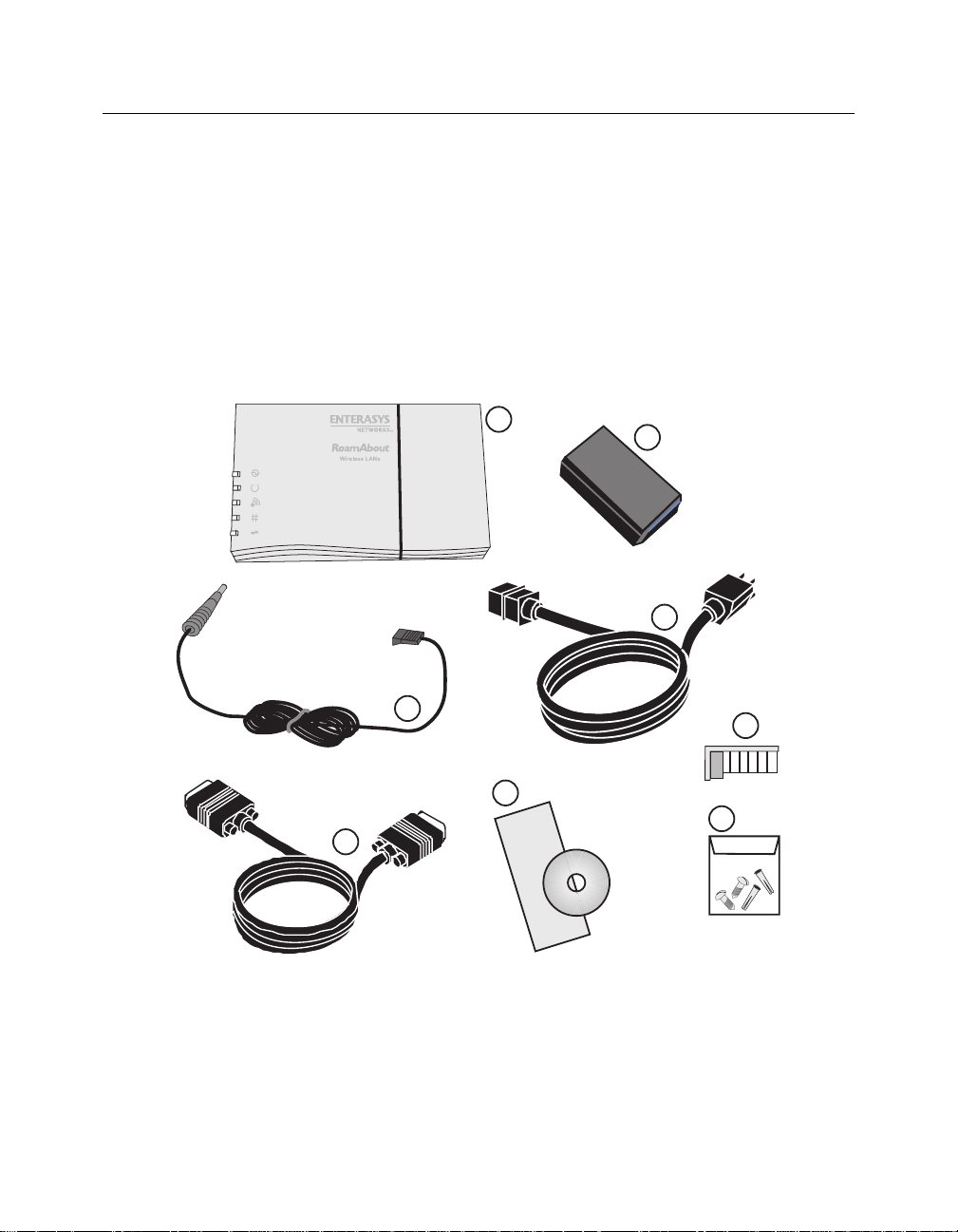
Components
The distribution kit contains the following components:
Unpacking and Inspecting
1
3
6
5
Quick
Start
2
4
8
7
Preparing for Installation 1-3
Page 18

Unpacking and Inspecting
Ethernet Adapter
Verify that the following components shipped with your Roam About Ethernet Adapter:
# Description
1 RoamAbout Ethernet Adapter
2 5.2V Universal AC to DC power adapter
3 DC Power Cable
4 AC Power Cord
5 RS-232 serial cable
6 • CD-ROM containing the RoamAbout Ethernet Adapter Manager
software and the RoamAbout Ethernet Adapter Installation and User’s
Guide in PDF. You can access this guide by selecting Help in the
RoamAbout Ethernet Adapter Manager Unit List Window.
• RoamAbout Ethernet Adapter Installation Quick Start
7 Mounting hardware
8 Combs, used in environments with extreme vibrations to prevent the PC
card from vibrating out of the socket.
1-4 Preparing for Installation
Page 19

Chapter 2
Configuration Overview
The RoamAbout Wireless Ethernet Adapter transforms wired devices (for example.,
desktop computers an d pr inters ) into wirel ess devices. Th e RoamAbou t Wi reles s Ethernet
Adapter is easily integrated into your existing wireless network.
The RoamAbout Wireless Ethernet Adapter can be used in the following wireless
topologies:
• Wireless infrastructure networks, which require the RoamAbout Access Point.
• Wireless ad-hoc networks, which do not require the RoamAbout Access Point
Wireless Infrastructure Network
In a wireless infrastructure network, wireless clients communicate with an Access Point (AP)
connected to a wired LAN. A RoamAbout wireless infrastructure can support clients with
various supported oper at in g sys t ems. Infrastructure mode is of t en us ed i n sy st ems t hat h a ve
heavy network traffic and want to utilize the filtering capabilities of the AP.
The AP remains as a stationary part of the wireless L AN, unlike individual Ethernet Adapter
units that can be physically moved throughout the wireless LAN. The Ethernet Adapter
synchronizes communication with the AP. Individual Ethernet Adapter units do not
communicate directly with each other. All communication between multiple Ethernet
Adapter units, or between an Ethernet Adapter unit and a wired network client, go through
the AP.
Multiple Access Points can be used to extend the coverage area.
Figure 2-1 shows an example of an infrastructure network.
Configuration Overview 2-1
Page 20
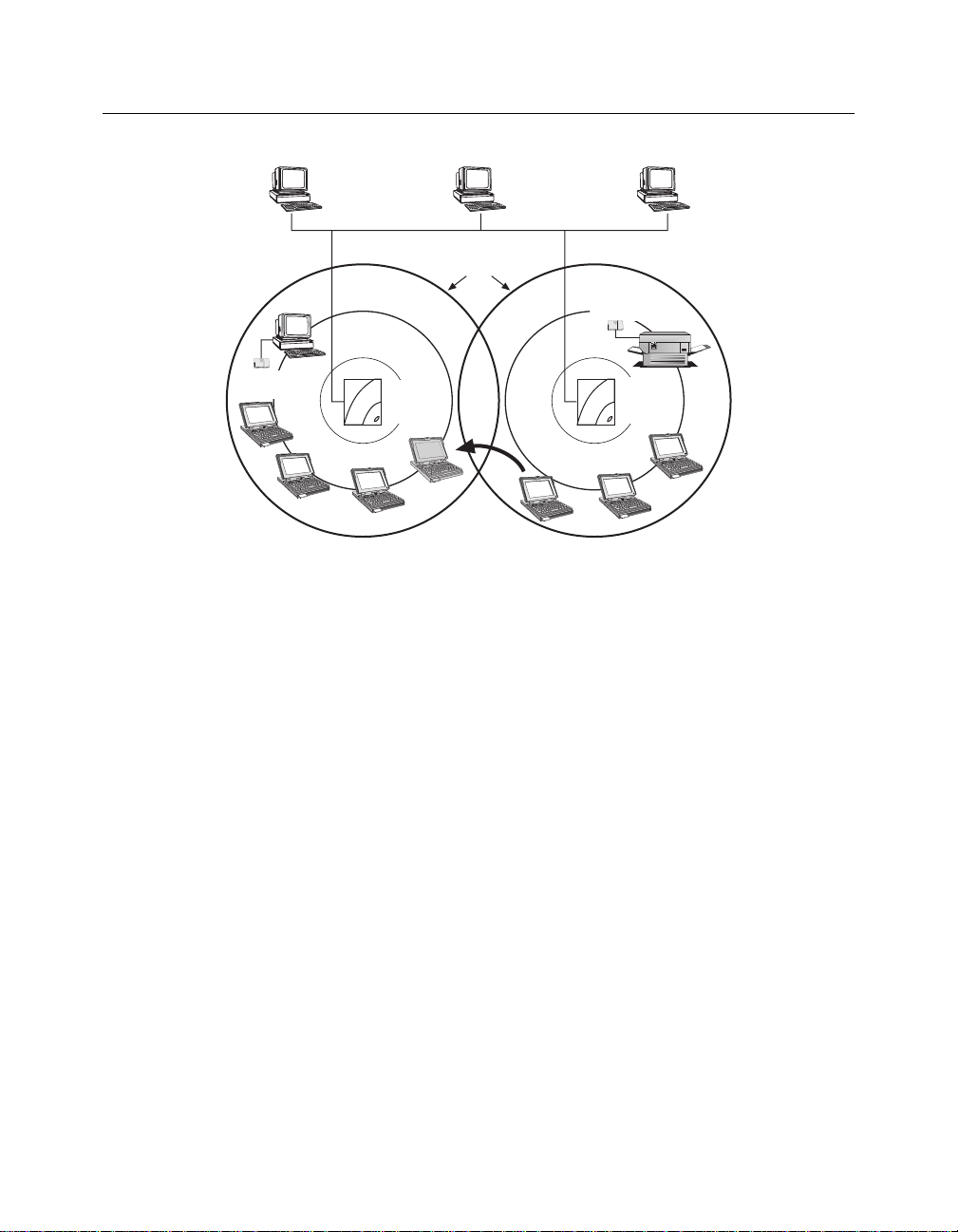
Wireless Infrastructure Network
Figure 2-1: Infrastructure Network Example
Ethernet
Adapter
Cell 1 Cell 2
AP1
Workgroup
Mode
Coverage
Areas
Ethernet
Adapter
AP2
Workgroup
Mode
Printer
Wireless
Client
The re-association capabilities of the IEEE 802.11 standard enable clients to move
throughout the wireless LAN area and roam between Access Points. Re-as so c iation can
occur as long as the Ethernet Adapter has the same network name as the AP to which it is
trying to make a connection.
2-2 Configuration Overview
Page 21
Wireless Ad-Hoc Networks
Wireless ad-hoc networks, also known as peer-to-peer or independent networks, do not
include Access Points. Instead, the ad-hoc network is a loose association, or workgroup, of
computers that can communicate with each other using the PC Card in Ad-Hoc Mode.
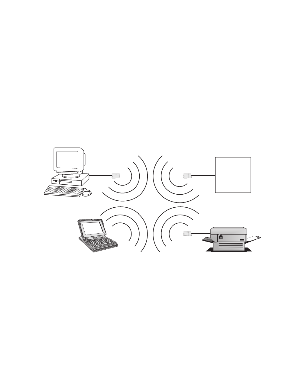
Figure 2-2 shows a network in which three Ethernet Adapter units are used to provide
wireless connectivity between Ethernet devices.
In this configuration, the Ethernet Adapter units and PC cards mak e all four devices appear
to be connected by the same Ethernet cable. Using Ethernet Adapter units in this manner
provides a cost effective way to wirelessly link a small number of Ethernet devices.
Figure 2-2: Ad-Hoc Network Example
Wireless Ad-Hoc Networks
PC
10bT
LapTop
Ethernet
Adapter
Ethernet
Adapter
Ethernet
Adapter
10bT
File Server
10bT
Printer
Configuration Overview 2-3
Page 22

Page 23

Chapter 3
Installation
This section describes how to install the RoamAbout W ireless Ethernet Adapter. It also
includes the installation of the PC (PCMCIA) wireless LAN card into the Ethernet Adapter.
NOTE
The Ethernet Adapter does NOT include a RoamAbout 802.11 DS PC card.
These cards are sold separately. Contact your Enterasys Representative for
more information.
Installation Procedure
To install the Ethernet Adapter, perform the following steps:
1) Remove your RoamAbout Ethernet Adapter from the packaging. The
Ethernet Adapter ships fully assembled. To install the PC Card and use the
Ethernet Adapter, some disassembly and re-assembly is required.
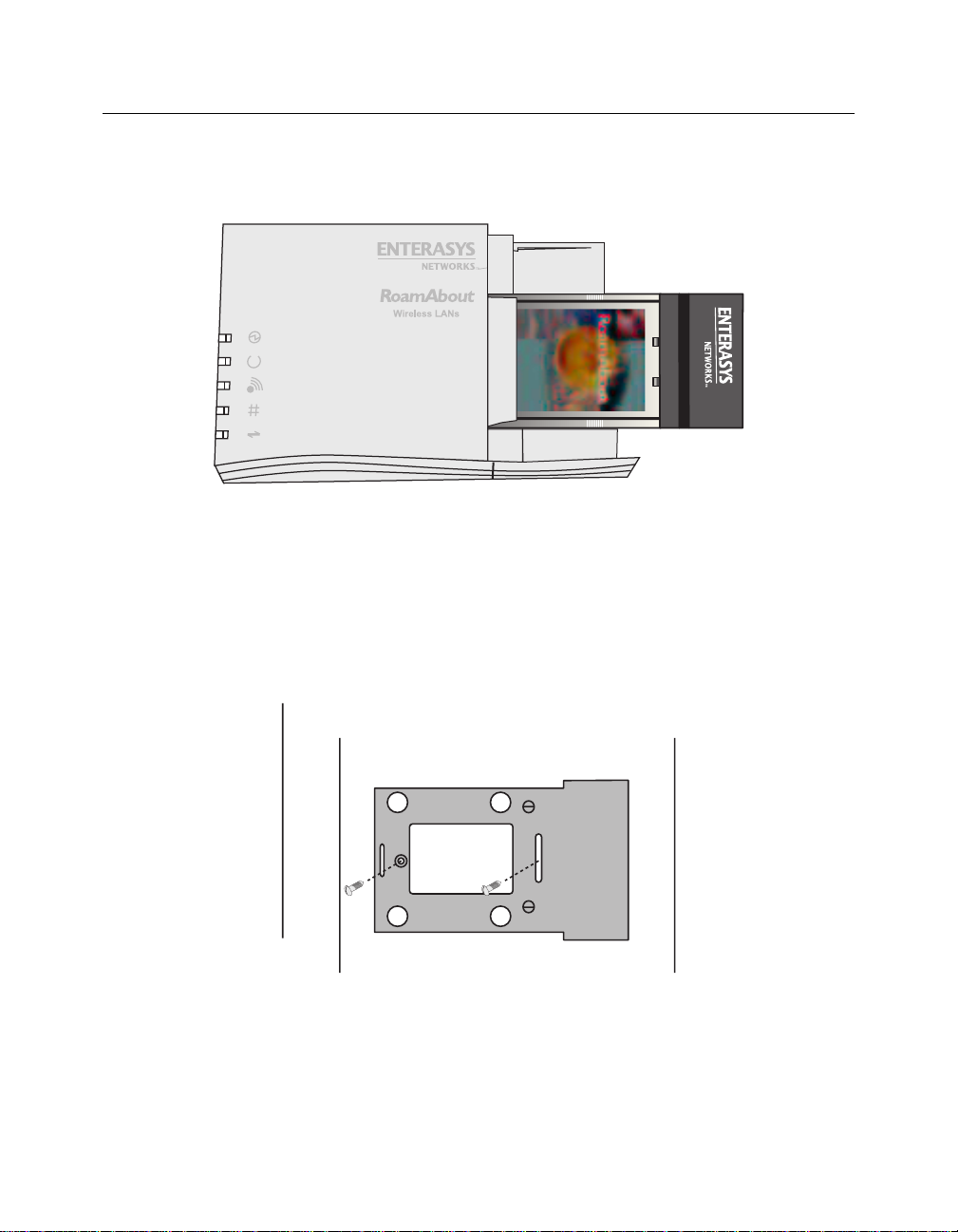
2) Remove the cap from the Ethernet Adapter by pressing on the side of the cap
to release it as shown in Figure 3-1. Removal of the cap reveals the PC card
slot.
Figure 3-1: Removing the Cap
Press Here
to Lift Cover
Installat ion 3-1
Page 24
Installation Procedure
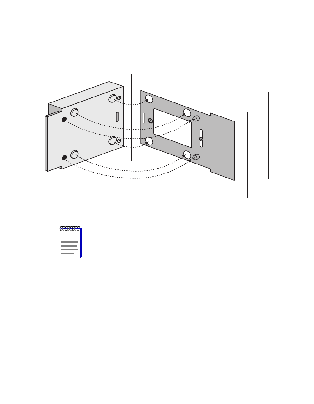
3) If you are planning to mount the Ethernet Adapter (optional), remove the
Figure 3-2: Removing the Bottom Mounting Plate
bottom mounting plate as shown in Figure 3-2.
3-2 Installation
4) Remove the small combs from the end cap.
The combs are generally not needed. The combs, when cu t to an approp riate
NOTE
size, are for use only when the Ethernet Adapter is in an environment with
extreme vibrations. The combs prevent the PC card from vibrating out of the
socket.
Page 25
5) Gently insert PC card (face up) into the designated slot as shown in
Figure 3-3.
Figure 3-3: Inserting the PC Card
Installation Procedure
W
IRELESS LA
NS
EN
JOY
TH
E FREEDO
M
O
F W
IRELESS NETW
O
RK
ING
Wi
Fi
Hi-Gigabit Matched Adapter
802.1 DS High Rate
6) Replace the cap on the Ethernet Adapter that you removed in step 3 by
snapping the cap straight down on the body.
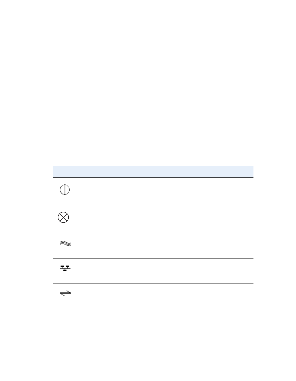
7) If you are mounting the Ethernet Adapter, install the bottom mounting plate
where desired as shown in Figure 3-4. Then, place the Ethernet Adapter onto
the mounting plate and snap it into place. Ensure that the Ethernet Adapter is
secure.
Figure 3-4: Installing the Mounting Plate (Optional)
8) Connect a standard, straight-through 10BaseT Ethernet cable between the
RJ-45 port on the Ethernet Adapter and the network port on the computer
where you will install the Ethernet Adapter Manager configuration software.
Installat ion 3-3
Page 26
Ethernet Adapter LED Indicators
9) Connect the six-pin DC power cable to the power supply.
10) Connect the AC power cord to the other side of the power supply.
11) Connect the round power plug to the Ethernet Adapter port labeled 5V DC.
12) Insert the AC power cord into the AC socket.
13) Verify the Ethernet Link LED is illuminated (Table 3-1), indicating a valid
Ethernet connection to your PC.
14) The RoamAbout Ethernet Adapter hardware is now ready for configuration
using the RoamAbout Ethernet Adapter Manager. Proceed to Chapter 4 to
install the Ethernet Adapter Manager.
Ethernet Adapter LED Indicators
As shown in Table 3-1, there are five LED indicators:
Table 3-1: LEDs
LED Description
Power. Lights green when power is applied.
3-4 Installation
Status. Lights amber when status information is available.
Radio Associated / Radio Activity. Lights green when the radio is
associated to another radio and lights amber during radio
communication.
LAN Link / LAN Activity. Lights green to show that a valid
Ethernet link is present on the 10BaseT port. Lights amber during
Ethernet activity.
Serial Transmit/Serial Receive. Lights amber when transmitting
data out the serial port and lights green when receiving data on the
serial port.
Page 27

Chapter 4
Ethernet Adapter Manager Installation
This chapter describes how to install and configure the Ethernet Adapter Manager.
The RoamAbout Ethernet Adapter Manager is used to configu re the Ethernet Adapter. You
can install it on a PC or workstation runni ng Windows 95/98/ NT/2000 or Millen nium. The
Ethernet Adapter Manager allows you to graphically and remotely:
• Display a list of Ethernet Adapter stations running on th e local network
• Display and edit the current Ethernet Adapter configuration
• Save and load configurations
• Update the Ethernet Adapter firmware
NOTE
Installation
To install the Ethernet Adapter Manager, perform the following step s:
The Ethernet Adapter Manager communicates with the Ethernet Adapter
using a non-routing protocol. Your Ethernet Adapter units must be
accessible on the local Ethernet network to communicate with the Ethernet
Adapter Manager.
1) Insert the Ethernet Adapter Manager CD-ROM into the CD-ROM drive.
If the installation program does not begin automatically , preform the
following steps:
a) Click on the My Computer icon on your desktop.
b) Click o n the icon for the CD-ROM.
c) Double-click on the setup.exe icon.
The Welcome window appears.
2) Click NEXT to continue the installation, or CANCEL to terminate.
The Software License agreement appears.
Ethernet Ad apter Manage r Installation 4-1
Page 28

Uninstall
Uninstall
To uninstall the Ethernet Adapter Manager, perform the following steps:
3) Click YES if you agree to the terms presented and allow the continuation of
installation. Click NO if you do not agree, and terminate the installation.
The Choose Destination window appears.
4) Choose the default path and location. Or, enter a selected path.
5) Click NEXT.
The Select Program Folder window appears. This window allows you to
change the name of the program folder created.
6) Click FINISH to complete the installation of the Ethernet Adapter Manager.
1) Select Start->Settings Control Panel .
2) Double-click on the Add/Remove Programs icon.
3) Select Ethernet Adapter Manager from the list.
4) Click on the Add/Remove button.
5) Click on the Uninstall button. The Uninstall button remains inactive for a
short period of time.
NOTE
4-2 Ethernet Adapter Manager Installation
If you uninstall the Ethernet Adapter Manager on Windows 95, you must
reboot your computer to remove it from the Program List on the Windows
task bar.
Page 29

Using the Ethernet Adapter Manager
Using the Ethernet Adapter Manager
Starting the Ethernet Adapter Manager.
To start the Ethernet Adapter Manager, select
Start-->Programs-->RoamAbout-->RoamAbout Ethernet Adapter Manager.
The RoamAbout Ethernet Adapter Unit List window appears (Figure4-1) and lists the
Ethernet Adapter units currently detected. All Ethernet Adapter units are controlled from
this main window.
Table 4-1: RoamAbout Ethernet Adapter Unit List
The RoamAbout Ethernet Adapter Unit List window buttons are:
• SCAN
Allows you to search for active Ethernet Adapter units. After a scan is executed, any
previously displayed Ethernet Adapter units that are no longer foun d are removed from
the list and found units are displayed.
• EXIT
Closes the Ethernet Adapter Manager.
• CONFIGURE
After selecting a unit, advances you to the first configuration window.
Ethernet Adapter Manager Installation 4-3
Page 30

Using the Ethernet Adapter Manager
• HELP
Launches this document. You need the Adobe Acrobat Reader to read this document.
Configuring the Ethernet Adapter
To configure the Ethernet Adapter, perform the following steps:
1) Highlight the Ethernet Adapter that you want to configure.
2) Click on the Configure button, or double-click on the desired Ethernet
Adapter listing. The Configuration window (Figure 4-1) appears displaying
information about the RoamAbout Ethernet Adapter Manager and the
selected unit.
Figure 4-1: Configuration Window
NOTE
The versions listed in the Configuration window may not match your actual
versions.
4-4 Ethernet Adapter Manager Installation
Page 31

Using the Ethernet Adapter Manager
The Configuration window File menu pull-down options allow you to:
• Save or load a configuration
• Reset the Ethernet Adapter to factory defaults
• Set a new password or clear it
• Access a view of the log files
• Update the Ethernet Adapter firmware
Table 4-2: Configuration Window Tab Information
Tab Name Action
Network Provides the configuration screens for the network
configuration.
Serial Provides the configuration screens for serial configuration.
Radio Provides the configuration screens for the PC Card.
Table 4-3: Configuration Window Button Information
Button Action
Close Closes the current configuration window.
Reload from Unit Allows you to discard the changes you have made to the
configuration and reload the current configuration from the
Ethernet Adapter to the Ethernet Adapter Manager.
Update and Reset
Unit
Downloads the parameters from the Ethernet Adapter Manager
to the Ethernet Adapter. During the download, a syntax check
is performed of all parameters. If the check is not successful,
an error message is displayed in the GUI Message Log
describing the errors and their location.
Ethernet Adapter Manager Installation 4-5
Page 32

Using the Ethernet Adapter Manager
Saving a Configuration
You can save the configuration settings of the Ethernet Adapter to a local file. This feature
allows you to restore settings to a known state, or easily co nfigure multiple Ethernet
Adapter units with the same settings.
1) Click on the Update and Reset Unit button. This synchronizes the
parameters in the Ethernet Adapter with those in the Ethernet Adapter
Manager.
NOTE
To ensure that you save your changes to a local file and the Ethernet
Adapter, you should always perform Step 1 (Update and Reset Unit) before
saving your configuration.
2) Go back to the Configuration window (Figure 4-1).
3) Click on the File menu and select Save Configuration.
4) Browse to the directory where you would like to save the current
configuration. The default path is the RoamAbout program directory.
5) Click Open. (In this case the Open button is used to save the file)
Loading a Configuration
The Ethernet Adapter Manager allows you to re load a saved configuration f ile to a selected
Ethernet Adapter.
1) Go back to the Configuration window (Figure 4-1).
2) Click on the File menu and select Load Configuration.
3) Browse to the direct ory which cont ains the sav ed configur ation that y ou want
to upload.
4) Select the desired configuration file and click on the Open button.
The configuration file parameters are displayed.
5) Go back to the Configuration window (Figure 4-1).
4-6 Ethernet Adapter Manager Installation
Page 33

Using the Ethernet Adapter Manager
6) To activate the parameters, click on the Update and Reset Unit button.
NOTE
that was in the Ethernet Adapter when the configuration parameters were
saved, all parameters but the PC card options are loaded from the file. You
will need to set the new PC card parameters manually. This procedure
allows you to change your PC card while keeping your network and serial
settings. You can save a new version of the configuration file so that future
loads will include the PC card para m eter settings.
Setting and Removing Passwords
Setting a password prevents unauthorized users from accessing or changing the settings on
your Ethernet Adapter. You will need to enter this password each time you want to
reconfigure the Ethernet Adapter. Enterasys Networks recommends that you set a password
for each Ethernet Adapter.
Setting a Password
To set a password, perform the following steps:
1) Go to the Configuration window (Figure 4-1).
2) Click on the File menu and select Set New Password.
3) Enter the password twice.
4) Click on Update Password Now.
If the PC card in the active Ethernet Adapter is different than the PC card
The new password is immediately active.
Removing a Password
To remove a password, perform the following steps:
1) Go to the Configuration window (Figure 4-1).
2) Click on the File menu and select Set New Password.
3) Clear the password fields.
Leaving the password fields empty removes the password. You are not
prompted for a password when the fields are empty.
Ethernet Adapter Manager Installation 4-7
Page 34

Using the Ethernet Adapter Manager
Upgrading the Ethernet Adapter Firmware
To update the firmware on your Ethernet Adapter, perform the following steps:
1) Download the latest version of firm ware from the RoamAbout W ireless web
site, www.enterasys.com/wireless, to the computer that is currently running
the Ethernet Adapter Manager. The firmware file will have the extension
“.rum”.
2) When the download is complete, go the Ethernet Manager Co nfiguration
window (Figure 4-1).
3) Click on the File menu and select Upload Firmware.
4) Browse to the directory which contains the location of the firmware file.
5) Double-click on the file.
The Log Viewer displays a progress status. At the end of the process, the
Ethernet Adapter resets. The Log Viewer displays a message that your
Ethernet Adapter was properly updated. The status light on the Ethernet
Adapter flashes. The new image is installed, and the Ethernet Adapter ready
for use, in approximately 15 to 20 seconds.
Resetting to Factory Defaults
This feature allows you to restore the Ethernet Adapter back to its origin al settings.
1) Go to the Ethernet Manager Configuration window (Figure 4-1)
2) Click on the File menu and select Reset to Factory Defaults. All of the
parameters are immediately restored to the factory default values.
Depending on your current PC card net work s etting, resetti ng to fact ory def ault may leave
the Ethernet Adapter in a non-reachable state. Resetting to defaults resets all parameters,
including the PC Card Network Name. If the Ethernet Adapter you reset to defaults is not
on the same wired LAN section as your PC, it is possible that it will lose association to the
Access Point. If this is the case, the Ethernet Adapter Manager cannot communicate with
the Ethernet Adapter. To resolve this problem, retrieve the Ethernet Adapter and connect it
to your PC via an Ethernet cable. Then, use the Ethernet Adapter Manager to set the
Network Name to match the Access Point.
4-8 Ethernet Adapter Manager Installation
Page 35

Changing Your PC Card Type
The Ethernet Adapter Manager is designed to detect the type of PC card you are cur rently
using, and to reset the specific radio parameters accordingly. To change the PC card and
retain the network and s erial parameters of your o ld radio type, perform the f ollowing steps:
1) With your current PC card, follow the instructions for saving a configuration
described in Saving a Configuration on page 4-6.
2) Remove power from the Ethernet Adapter, switch your PC card, and return
power to the Ethernet Adapter.
3) Reset to factory defaul ts by follo wing the instru ctions descri bed in Resetting
to Factory Defaults on page 4-8.
4) Load the configuration you just saved by following the instructions described
in Loading a Configuration on page 4-6. All non-radio parameters will be
retrieved.
5) Set the specific parameters of your new PC card by followin g the instructions
described PC Card Configuration on page 4-12.
Using the Log Viewer
The Log Viewer is used to:
• display the different logs and tables stored on the Ethernet Adapter.
Using the Ethernet Adapter Manager
• display status and error messages from the Ethernet Adapter Manager.
To open the Log Viewer, perform the following steps:
1) Go back to the Configuration window (Figure 4-1)
2) Click on the File menu and select SHOW LOG WINDOW. The Log View
window (Figure 4-2) appears.
The Log View window File menu allows you to switch views between the different
Ethernet Adapter logs and the Ethernet Adapter Manager utility messages.
Ethernet Adapter Manager Installation 4-9
Page 36

Using the Ethernet Adapter Manager
Figure 4-2: Log View Window
GUI Message Log
The Show GUI Message Log displays status messages from the Ethernet Adapter Manager.
Event Log
The Event Log displays messages generated by the Eth ernet Adap ter. Ev ent log messages
include basic information about the Ethernet Adapter hardware and any status messages
generated by the Ethernet Adapter.
• To display the event log of your Ethernet Adapter, select the Read Event Log option
from the File menu.
• To clear the entries from the event log, select the Clear Event Log option from the
File menu.
Roaming Log
The Roaming Log records association and disassociation events. Each association event is
recorded with a timestamp and, if available, the Access Point MAC address. Each
disassociation event contains only a timestamp. The timestamp indicates the number of 10
millisecond periods since the unit was turned on or reset. For example, a timestamp of 6000
corresponds to a time of 60 seconds, and a timestamp of 20 corresponds to a time of
0.2 seconds.
4-10 Ethernet Adapter Manager Installation
Page 37

Forward Table
The Forward Table (Figure 4-3) displays the MAC addresses detected by the Ethernet
Adapter. The table lists the interface, wire or PC card, where each MAC address was
observed. The time for each entry indicates the number of seconds until that entry is
removed from the forwarding table.
Figure 4-3: Forwarding Table
Using the Ethernet Adapter Manager
Ethernet Adapter Manager Installation 4-11
Page 38

PC Card Configuration
PC Card Configuration
This section describe s how to add the Ethern et Adapter to your wire less network. When the
Ethernet Adapter has joined your wireless network, the PC card association LED is green.
To configure the PC card settings, perform the following steps:
Basic Tab Page
1) Open the configuration window for the desired Ethernet Adapter, as
described in Using the Ethernet Adapter Manager on page 4-3.
2) Click on the Radio tab. When the Radio tab is highlighted, new horizontal
tabs appear: Basic, Advanced, and Encryption (see Figure 4-4). The
Encryption tab may not app ear if this option is not suppor ted by your PC card.
Figure 4-4: Radio - Basic Tab Page
4-12 Ethernet Adapter Manager Installation
Page 39

PC Card Configuration
3) Enter the Network Name. The Network Name must match the Access Po int,
or match the name to which you will use to establish a Ad-Hoc network. The
Network Name is case sensitive. The Network Name is used to specify a
unique IEEE 802.11 wireless network. Wireless Ether net Adapters un its use
the Network Name to associate to a specific Access Point (AP). Only devices
with the same network name will associate with each other. Alphanumeric
values may be used in this field.
4) Enter the Station Name. The Station Name is an identifier for each Ethernet
Adapter. The value supplied in this field is for conven ience in identifying the
Ethernet Adapter units with software, such as the Ethernet Adapter Manager.
5) Select the Network Operation.
a) Select Access Point if your configuration includes Access Points. Select
Ad-hoc if your configuration does not include Access Points.
b) Click o n th e Update and Reset Unit button. The Ethernet Adapter
Manager Message Log appears with a message stating that the update
was successful.
Ethernet Adapter Manager Installation 4-13
Page 40

PC Card Configuration
Advanced Tab Page
The Advanced configuration, shown in Figure 4-5, is specific to the feature set of your
wireless LAN card. Consult your PC card documentation for appropriate settings.
Figure 4-5: Radio - Advanced Tab Page
1) Select the MAC Address option. There are three options:
Detect - detects the first packet received on the wired side, not the radio side.
This feature sets the MAC address used by the wireless LAN interface. Check
to ensure that the unit is set to DETECT. Enterasys Networks recommends to
set this option to DETECT, unless you are performing an advanced
configuration.
Built-in - Uses the radio MAC Address.
Manual - you enter a MAC Address.
2) Select the AP Density.
4-14 Ethernet Adapter Manager Installation
Page 41

PC Card Configuration
3) Select the Transmit Rate from the drop-down menu.
4) Click on the Update and Reset Unit button.
Encryption Tab Page
The Encryption tab (Figure 4-6) may not appear if your PC card does not support this option.
Encryption is necessary to associate to an Access Point which is configured to deny
unencrypted connectio ns . Co ns ul t your PC card documentation for a d et ail ed des cri pt ion of
how to set up encryption. In many cases, you will want encryption enabled to provide
security for data being sent across the wireless part of your network.
Figure 4-6: Radio- Encryption Tab Page
To use encryption, perform the following steps:
1) Click on the Enable Encryption box.
2) Select the Transmit Key.
Ethernet Adapter Manager Installation 4-15
Page 42

PC Card Configuration
3) Enter up to four encryption key values.
The values for the encryption keys may to be written as either text (ASCII)
strings or hexadecimal numbers. Hexadecimal values must be preceded by
“0x” and are composed of the numbers 0 to 9 and the letters A to F. Text
strings cannot begin with“0x”.
The level of encryption corresponds to the length of the encryption key. Refer
to the PC card d ocumentation for the encryption levels s upport ed by you r PC
card.
Encryption
Level
HEX ASCII
Key Length
Example
40 bit 0x + 10 digits 5 characters 0xFEDCBA9876
128 bit 0x + 26 digits 13 characters EnterasysRMBT
4) Select a transmit key. The transmit key is the encryption key used by the
Ethernet Adapter to encrypt messages sent over the radio. Messages received
by the radio are decrypted if they were created using any of the four keys.
5) Click on the Update and Reset Unit button. If you are configured to run in
Infrastructure Mode, the Ethernet Adapter associates to the Access Point with
the specified Network Name.
4-16 Ethernet Adapter Manager Installation
Page 43

Configuring the Ethernet Adapter to Connect to a Wired Ethernet Device
Configuring the Ethernet Adapter to Connect to a Wired
Ethernet Device
You can configure the Ethernet Adapter as a wireless device to connect to a wired unit, such
as a computer or Ethernet printer, to your wireless network. The Ethernet Adapter can act
as a wireless device, in addition to performing any one of the serial port applications
discussed in the following chapters.
To configure the Ethernet Adapter to connect to a wired Ethernet device, perform the following
steps:
1) Complete the PC card configuration instructions described in PC Card
Configuration on page 4 -12.
2) Click on the Update and Reset Unit button.
3) If necessary, move the Ethernet Adapter to the desired location. Provide
power to the Ethernet Adapter and connect it to the Ethernet device.
Your Ethernet Adapter is now configured to act as a wireless device connected to your
wired Ethernet network component.
Ethernet Adapter Manager Installation 4-17
Page 44

Network Configuration
Network Configuration
This section describes the network settings necessary to communicate with the Ethernet
Adapter.
Communicating directly with the Ethernet Adapter provides:
• the ability to use the serial port applications.
• the ability to ping the Ethernet Adapter.
• the ability to remotely configure the Ethernet Adap ter via the telnet protocol.
To configure the network settings, perform the following:
1) Ensure that you complete the PC card configuration described in the PC
Card Configuration section on pa ge 4-12.
2) Click on the Network Tab.
3) Click on the Basic tab. The Network Basic tab page is shown in Figure 4-7.
4) Enter the IP address that you want assigned to the Ethernet Adapter. The IP
address is the network address that will be used by other compu ters to
communicate with the Ethernet Adapter.
5) Enter the Netmask. This is a value that defines the range of IP addresses
available within your local network.
4-18 Ethernet Adapter Manager Installation
Page 45

Figure 4-7: Network - Basic Tab Page
Network Configuratio n
6) Enter the IP address of the gateway i f your netw ork uses a gateway (rou ter or
firewall). You need to ent er the IP address of your gat eway if you plan t o use
the Ethernet Adapter to access computers or other Ethernet Adapter units
beyond your Internet router or firewall. A gateway entry is only needed for
serial applications that actively connect to an IP address outside your local
area network. You may enter “none” in this field if no gateway is present or
a gateway is not needed..
NOTES
• A gateway is not necessary if you are connecting to a wired Ethernet
device.
• The Ethernet Adapter does not support DHCP.
Ethernet Adapter Manager Installation 4-19
Page 46

Page 47

General Serial Configuration
This chapter describes the general serial settings that are required for all serial port
applications. For proper operation, the settings of the Ethernet Adapter always match the
settings of the device to which it is connected via the RS-232 port. There are two gro ups of
parameters that need to be configured to accomplish this task: the UART Settings and the
Flow Control Settings.
Configuration Flowchart
Figure 5-1 can assist you with the Ethernet Adapter configuration. Start at the top of and
move downward towards the des ired configuration. As you move down the flowchart , there
are bulleted lists of configuration parameters that you need to set to accomplish that
configuration. The flow chart only lists the parameters that need to be modified for proper
operation.
Chapter 5
General Serial Configuration 5-1
Page 48

Configuration Flowchart
Figure 5-1: Configuration Flowchart
RoamAbout
Ethernet
Adapter
Network Name
RoamAbout
Access
Point
Network
Serial
Port
IP Adress
Netmask
Gateway
Socket
Listen
Method
Local Port Remote IP
Socket
Connect
Method
Remote Port
Command
Prompt
Method
Serial
Telnet
Client
IP Adress
Netmask
Gateway
RMP
Pipe
Wait For
Keystroke
Method
Remote IP
Application
Serial
Line
Replacement
Serial
Port
Baud Rate
Data Bits
Stop Bits
Parity Bits
Flow Control
LPD
Print
Server
IP Adress
Netmask
Gateway
TCP
Pipe
IP Adress
Netmask
Gateway
Remote IP
Remote Port
Local Port
5-2 General Serial Configuration
Page 49

UART Settings
UART (Universal Asynchronous Receiver/Transmitter) is the fundamental hardware for
serial communication. It controls the speed and method of data transfer of the serial port.
To configure the UART settings, perform the following steps:
1) Clicking on the Serial tab.
2) Click on the UART tab. The UART tab page is shown in Figure 5-2 with the
default settings.
Figure 5-2: Serial - UART Tab Page
UART Settings
3) Select the baud rate of your device from the pull-down menu. The baud rate
indicates the data transfer rate of the serial port. The baud rate ranges from
300 to 115200 bps. Standard rates are 300, 12 00, 2400 , 9600, 19 200, 384 00,
57600, 115200.
General Serial Configuration 5- 3
Page 50

UART Settings
4) Check the Data Bits setting of the device you are connecting to the Ethernet
Adapter. Choose the Data Bits setting that matches the Data Bits setting of the
device you are connecting to the Ethernet Adapter. Data Bits determine the
number of bits used to transmit data. The possible values are 7 and 8.
5) Check the Stop Bits setting of the device you are connecting to the Ethernet
Adapter. Choose the Stop Bits setting that matches the Stop Bits setting of the
device you are connecting to the Ethernet Adapter. Stop Bits determine the
number of bits used to represent an end of a character. The value can be 1 or 2.
6) Check the Parity Bit setting of the device you are connecting to the Ethernet
Adapter. Choose the Parity Bit setting that matches the Parity Bit setting of
the device you are connecting to the Ethernet Adapter. They parity bit is used
to check for correct data transmission. Options are: none, even, and odd.
5-4 General Serial Configuration
Page 51

Flow Control
Flow control is the process of adjusting the flow of data from one device to another to
ensure that the receiving device can handle all of the incoming data. Flow control becomes
an important factor when one of the devices is capable of transmitting data at a rate faster
than the other can receive it. There are two basic types of flow control, Hardware and
Software.
Hardware Flow Control
Hardware flow control uses dedicated signal lines to dictate transmission of data. The
options that allow you to select which pair of lines to use for this type of flow control are:
• RTS/CTS = Request To Send/Clear To Send
• DTR/DSR = Data Terminal Ready/Data Set Ready
Flow Control
NOTE
The Windows flow control setting, “Hardware,” uses the RTS/CTS pair of
flow control lines.
Software Flow Control
Software flow control uses two special characters, called “Xon” and “Xoff”, which are
embedded in the data to turn on or off the tran smission of data fro m the source to receiver.
In the incoming direction, flow control prevents the Ethernet Adapter from sending data
when the computer is not ready to accept it. With incoming flow control on, the Ethernet
Adapter will interpret Xon/Xoff characters in the data stream entering the serial port of the
Ethernet Adapter as flow control signals. The Xon/Xoff characters are not considered data
and therefore are absorbed by the Ethernet Adapter.
The outgoing software flow control option specifies the generation of Xon/Xoff flow
control characters by the Ethernet Adapter. The control characters are sent out the serial
port of the Ethernet Adapter and instruct the computer to start or stop sending data. This
option is used to prevent the computer from sending data when the Ethernet Adapter is not
ready to accept it.
Software flow control can have both incoming and outgoing mechanisms running
simultaneously, individually, o r no t at all (as is the default).
General Serial Configuration 5- 5
Page 52

Flow Control
Flow Control Configuration
To configure the Ethernet Adapter flow control, perform the following steps:
1) Click on the Flow Control tab. Figure 5-3 shows the Flow Control tab page
with the default settings
2) Check the flow control settings of the device that you are conn ecting to the
Ethernet Adapter. Change the Ethernet Adapter settings to match those of the
connected device by clicking on t he corresp onding but tons. The flow con trol
and the device settings must match. For example, if you are connecting to a
device that is using RTS/CTS hardware flow control, set the Ethernet Adapter
hardware flow control settings to RTS/CTS.
Figure 5-3: Flow Control Tab Page
.
Serial Packets
The parameters on this tab page control the serial to network packet conversion process.
Most users will not need to change the Serial Packet Parameters. These parameters control
the way that data received on the serial port is divided into Ethernet packets.
5-6 General Serial Configuration
Page 53

Chapter 6
Wireless Printing
This chapter describes how to configure the Ethernet Adap ter to enable wireless printing to
a serial printer. If you have an Ethernet printer this section does not apply. To connect to
an Ethernet printer, follow the instructions to configure the Ethernet Adapter to a wired
device in Chapter 4.
The LPD protocol requires an operating system that supports LPD to a remote host, such
as Windows. The LPD server on the Ethernet Adapter uses a unidirectional protocol
wherein data is received via a network connection and sent out the serial port to the printer.
Data received from the serial port is ignored. This means the Ethernet Adapter ignores data
received from the printer except for software flow control characters. See Software Flow
Control on page 5-5.
NOTE
When configuring your operating system, use the network host name or IP
address of the Ethernet Adapter as the remote printer host.
Configuring the Ethernet Adapter to Enable Wireless Printing
To configure the LDP print server for serial printing, perform the following steps:
1) Complete the Basi c Radio Confi guration inst ructions descri bed in Chapter 4.
2) Complete the Network Configuration described in Chapter 4.
3) Complete the General Serial Configuration described in Chapter 5.
4) Click on the Serial tab and then select the Protocol tab.
5) Click on the LPD option.
Wireless Printing 6-1
Page 54

Configuring the Ethernet Adapter to Enable Wireless Printing
6) Click on the Flow Control tab. Verify that the Flow control settings of your
Ethernet Adapter match those of your printer.
NOTE
printing. See your printer manu al for reference on how to configure Flow
Control settings in your printer.
7) Click on the Update and Reset Unit button to complete the configuration.
The Ethernet Adapter is now configured to act as a LPD print server for your
serial printer.
If the Flow Control settings do not match, there will likely be errors when
6-2 Wireless Printing
Page 55

Appendix A
Terminal Configurator
This appendix describes how to use the Terminal Configurator to configure the Ethernet
Adapter.
The Terminal Configurator is an alternate method used to configure your Ethernet Adapter.
The Terminal Configurator is a text-based configuration method. You can access the
Terminal Configurator by one of the following methods:
• Through direct serial connection. When using a direct serial connection, the
Ethernet Adapter communicates with a serial terminal or a computer that is
running terminal emulation software. Some common examples of terminal
emulation software include HyperTerminal, ProComm, and Telix.
Configuration usi ng a direct serial connection can be performed at any time,
regardless of the current settings of the Ethernet Adapter.
• Over a telnet connection. When using a telnet connection, the unit
communicates via TCP/IP with a computer running a telnet p rogram. A telnet
connection can be used to configure Ethernet Adapter units outside of your
local area network, when the Ethernet Manager cannot be used, because the
TCP/IP communication is routeable.
A-1
Page 56

Establishing a Direct Serial Connection
Establishing a Direct Serial Connection
This method of configuring and managing an Ethernet Adapter uses a serial cable
connected from the Ethernet Adapter to a computer r unning terminal emulation software.
To configure the Ethernet Adapter using the Hyperterminal program, perform the
following steps.
1) Follow the Hardware Installation instructions num bered 1-9, in Chapter 3.
2) Connect the included serial cable into your computer’s serial port.
NOTE
The PC’s COM port you p lugged thi s cable in to. Plug the o pposite end of th e
serial cable into the serial port on the Ethernet Adapter.
3) On your desktop, click on the Start icon.
Select Programs-->Accessories-->Hyperterminal.
4) Double-click on the Hypertrm.exe file.
The Connection Description screen appears. This screen allows you to insert
a connection name into the Name field. This name can be any alphanumeric
combination.
5) The Connection Description screen contains a field entitled Icon. Do not
change the default settings.
6) Click OK to proceed using Hyperterminal. Use the CANCEL button to
terminate Hyperterminal.
The Phone Number screen appears. The fields Coun try Code, Area Code, and
Phone Number should be blan k by default. Do not chang e the default settings.
7) In the Connect Using field, choose the COM port that you plugged the RS-
232 cable into from the pop-up box options.
8) Click OK. The COMx Settings screen appears.
A-2
9) Select 9600 in the field labeled Bits per second. Leave the default of 8
selected for the Data Bits field. Parity should be left at its defaul t of None.
Stop bits should be left at its default of 1.
Page 57

Establishing a Direct Serial Connection
10) Choose None for the Flow control option.
NOTE
always be exactly as described here, regardless of the General Serial
Settings (Chapter 5).
11) Click OK after all of the COM settings have been chosen.
The next screen appears blank.
12) To bring up the local console management for the Ethernet Adapter, insert
one end of something similar to a to oth pick into the “config.” hole located
near the serial port on the Ethernet Adapter.
The Terminal Configurator appears on th e screen. You have now successfully
opened a direct serial connection to Terminal Configurator!
If the Ethernet Adapter does not respond within a few seconds after pressing
the Configure button and is connected to power perform the following steps:
a) Disconnect the power for a few seconds
b) Reconnect the power.
c) Press the configuration button again. If the terminal displays random
characters, check the baud rate and bit settings in your terminal
emulation software to insu re 9600 baud, 8 data bit s, no parity, and 1 s top
bit.
The serial port settings needed fo r use by the Terminal Configurator will
NOTE
If, after performing the above step, the Ethernet Adapter does not respond
with the configuration mode main menu, verify th at there is not a cable
problem by observing the green “Serial TX” LED when pressing the ENTER
key on the PC. Each time the key is pressed, the "Serial TX" light should
blink faintly and quickly. If the “Serial TX” light is not blinking, there may
be a problem in the cable connection. If the "Serial TX" light blinks when the
ENTER key is pressed and the unit does not respond, check to see if the
serial configuration is set to 8 data bits, no parity, 1 stop bit.
A-3
Page 58

Establishing a Telnet Connection
Establishing a Telnet Connection
This method opens a Telnet connect ion to th e Terminal Confi gurator on po rt 23. Por t 23 is
the default for most Telnet programs. This only works after the Ethernet Adapter is
assigned a TCP/IP address. If you need to assign the Ethernet Adapter an IP address you
need to use the Ethernet Adapter Manager or the Termin al Configurator using a direct serial
connection.
To establish a Telnet connection, perform the following steps:
1) Click on the Start menu and select Run…
2) Enter telnet xxx.xxx.xxx.xxx where xxx.xxx.xxx.xxx is the IP address of the
unit you want to configure.
The Terminal Configurator appears on th e screen. You have now successfully
opened a telnet connection to Terminal Configurator!
Using the Termin al Configurator
Once you have established a connection to the Terminal Configurator, the Main Menu
screen appears.
A-4
• Use the arrow keys to move the hi ghlighted bar. If the arrow key s don’t work,
you can move the bar by holding down the Ctrl key while pressing N (for
Next) and P (for Previous) to move the bar . To select an entry, press the Enter
key.
• To modify the configuration, as described in the following sections, select the
menu item Edit co nfiguratio n . Another menu, listing available files to edit,
is displayed. Selecting one of them will bring up an editor that you can use to
modify the file. File selection and editor operation are described below.
• After you have finished configuring the Ethernet Adapter, select the Reset
the Unit menu item, and then answer Yes to the confirmation. This resets the
device, allowing the new configuration to take effect as well as place it into
operating mode. Now you are ready to use your new configuration.
Page 59

Main Menu Overview
The section provides a list of main menu selections and their functions.
Resume operation
This option exits Configuration. It returns the Ethernet Adapter to the settings the Ethernet
Adapter had before the Configure button was pressed.
Edit configuration
Brings up a list of files to edit. Descriptions of the files and their contents are below.
View configuration for capture
If you select this option, it will give you an opportunity to enable capture mode in your
terminal software. It will then display all configuration settings and give the option to
disable capture mode. This option can be used to keep a record of the settings made for a
particular Ethernet Adapter unit, or to generate a file for Enterasys RoamAbout Technical
Support if you have any difficulties.
Reset configuration to default
Sets all configuration files to their factory default. A confirma tion dialog box appears to
verify the selection, so changes may or may not take place.
View forwarding database
Lists the MAC addresses of all network nodes detected, and the networ k interface of which
they were last listed.
Using the Terminal Configurator
View roaming log
Lists the MAC addresses of the Access Points that the Ethernet Adapter had association/
disassociation.
View system error log
Shows a list of errors if any have occurr ed. Use this option if the Eth ernet Ad apter’s E rror
LED is lit to see what kind of error the Ethernet Adapter is generating.
Clear system error log
Removes all messages from the error log described above.
Reset the Unit
Performs a hardware reset. Use this after making configuration changes to allow the
changes to take effect.
A-5
Page 60

Using the Terminal Configurator
Edit Configuration Menu
The Edit Configuration menu contains three selections/Config files to edit.
Return to Main Menu
Goes back to the previous menu selections.
System
Brings up the editor screen with the configuration file for opti ons that are not
communication dependent.
RS-232 port (uart0)
Brings up the editor screen with the conf iguration file for the s erial port and per-connecti on
network settings.
Bridged ethernet (lan0)
Brings up the editor screen with the configuration file for the radio parameters and IP
network interface settings.
The Editor
Selecting one of the configuration files listed in the previous section opens that file in the
editor. Once inside the editor, you may use arrow keys to move the cursor around. If the
arrow keys do not work wi th your termin al emulator , use Ctrl-P for u p [prev ious], Ctrl-N
for down [next], Ctrl-B for left [back], and Ctrl-F for right [forward] for cursor motion.
A-6
For faster motion, you can use Ctrl-A to jump to the beginning of the line, and Ctrl-E to
jump to the end.
To make changes in the Editor, mov e the cu rsor to the p oint yo u wan t to chan ge an d en ter
the change. To delete text behind the cursor, move the cursor to the positi on immediately
following the character to remove and press the Backspace key, Delete key, or type Ctrl-
H. To delete text in front of the cursor, press Ctrl-D. To delete text from the cursor to the
end of the line, press Ctrl-K.
After editing is completed, please save these changes by pressing Ctrl-W. After the
changes are saved the Edit Configuration menu returns to the screen. Although changes will
be saved, they will not take effect until you power the Ethernet Adapter off and back on. If
you decide that you don’t want to save the chang es you have made, pr ess Ctrl- X. You are
prompted for confirmation, then returned to the Edit C onf iguration menu.
If while typing the screen display becomes corrupted or confused press Ctrl-L to force a
screen redraw. Corruptions or confusions may occur due to many terminal emulation
software packages not emulating VT100 correctly.
Page 61

Configuration File Format
The configuration file format is bro ken down into sections that define a particul ar grouping
of options. Each section contains at the top a section header which is a string of text
surrounded by square brackets: [ ] (the section title). After each section header, there is a
list of entries containing equal signs. The text before the equal sign is a key and the text
after the equal sign is the val ue. Changi ng th e value of di fferent keys is how configur atio n
changes are performed. For example, the first two lines of the uart0 RS-232 file:
[hardware]
baud = 9600
In this example, “hardware” is the name of a section. Until the next section name in the file,
all entries must be either key/value pairs (such as the “baud = 9600” entry) or comments.
Key/value pairs listed before a section na me are invalid.
Comments may be stored in the configuration file by inserting a pound sign (#) before the
text to be added. This allows room for an explanation as to why certain settings have been
made, who made the changes, etc. Anything may be written in a comment, but the comment
ends at the end of the line. Multi-line comments are done by inserting the # at the beginning
of each line. For example:
# This is a comment.
Using the Terminal Configurator
File contents
System
[configure]
This contains settings that pertain to the operation of the Configu r ation menus. Currently,
there is only one: password.
The password allows the setting of a password that will be asked for upon entry to the
Configuration screen. Up to 12 alphanumeric characters is accepted. Do NOT use any
characters other than numbers and letters in this password. Although the password is not
hidden from the screen while editing, it is hidd en when entering configuration.
# This is line #2 of the comment.
this = no comment
A-7
Page 62

Using the Terminal Configurator
[bridge]
Bridge provides variables that are common to all radios. Bridge affects the behavior of
radios.
AP refresh period. Periodically an Ethernet Adapter pings an Access Point.
The AP Refresh Period is the time, in units of seconds, between pings. The
default for this value is 60 (which should be left at this default). If this default
is changed, there is a chance that the Access Point will not find the Ethernet
Adapter unit on the network.
NOTE
Ethernet Adapter.
RS-232 port (uart0)
[hardware]
RS-232 serial UART configurations found on all UARTS.
• baud. This selects the data transfer rate of the RS-232 serial port. The baud
rate can be anywhere between 112.5 an d 115,200 bps. All standar d rates (300,
1200, 2400, 9600, 19200, 38400, 57600, and 1 152 00) are cl ocked preci s el y,
but values in between will be roun ded to the closest possible hardwar e setting.
Closest possible hardware setting does not mean that the value will be
Having this refresh period active will not effect the performance of the
NOTE
rounded to one of the standard rates. The Ethernet Adapter’s UART is fully
capable of operating at non-standard speeds. The resolution of possible
baud rates is smaller at lower baud rates than at higher baud rates.
• data bits. In a UART character frame, this selects the number of bits that are
used to transmit data. Possible valu es are 7 and 8.
A-8
• parity. This sets the parity used in the UART character frame to check for
correct data transmission. Options are none, odd, and even.
• stop bits. Selecting the number of bits used to represent an end of character
bit in the UART frame. The value can be 1 or 2.
Page 63

Using the Terminal Configurator
[software]
The [software] section is used to control the receiving and send ing of b ytes over the serial
port. Proper setting of these values can significantly enhance the efficiency of data
transmission because the radio is “packet based” and the UART is “stream based.”
Stream based data means that the data is transmitted and received one byte at a time,
without any mechanism to sep arate chunks of d ata f rom oth er chunks of dat a. The devices
generating and using the data prod uced by the stream based pack et determines how the data
is delimited. Additionally, the devices also determine the meaning of the packet.
Packet based data means that the data is grouped into chunks then wrapper information is
added to this data specifying the destination of the data. Computer networks are packet
based by design. The radio in the Ethernet Adapter is really a computer network interface,
so the Ethernet Adapter’s radio is packet based.
This becomes important as the data is moved between the UART and the radio. When data
is received over the radio, sending it to the UART is simple. The wrapper information is
removed and the data inside the wrapper is sent out the serial port as fast as it can go.
However, data being received over the serial port must be converted into packets.
In order to perform this conversion, the Ethernet Adapter must be given a set of rules that
tell it that it is okay to start transmitting the data already received. The data cannot be
transmitted as soon as it is received, because as explained earlier there is overhead in the
radio transmitting process.
The values in this section define these conversion rules.
These rules don’t change the data. They specify when data can be
NOTE
transmitted over the radio.
• line length. Data is transmitted over the radio once the maximum number of
characters has been achieved. The line length default is 1408. Once 1408
characters have been received by the UART, these characters of data will be
transmitted regardless of the content of the data. This value can range from 1
to 1408, but be cautious of using values too small for they could result in data
loss.
• input timeout. The Input timeout is how long the Ethernet Adapter will wait
after some data has been received on the UART before giving up on waiting
for more. Once a character has been received the timer starts with this timeout. If the timer expires, the data is considered to be complete and gets
A-9
Page 64

Using the Terminal Configurator
transmitted immediately. Conversely, if another character is received before
this time-out, the timer is restarted from the beginning. The range for this
value is from 10 to 65 536 mill iseconds, thoug h it will al ways round u p to the
nearest tens of milliseconds. For instance, setting the time-out to 55 will mean
the Ethernet Adapter will wait for 60 milliseconds before giving up and
transmitting the data.
• delimiters. Delimiters are special characters that specify the end of the
data. Once any of the characters listed in this option are received, the data is
transmitted immediately. In serial communications, there is frequently a
character reserved to mean “end of transmission”. In human-interface
applications, this character is the “newline” or Enter key. For computer to
computer communication, this value may be different. If one exists, adding it
to this list will greatly improve communication efficiency. Up to four
delimiters can be listed here. They are specified as a space separated list of
ASCII values. The values can be written as decimal or hexadecimal numbers.
• protocol. The data format of the communication between the UART and
radio network is defined by the [protocol]. Possible values are passthrough,
passthrough2, telnet, and LPD.
— Passthrough forwards any data received over the UART or radio
interfaces to the other interface with the data unchanged.
— Passthrough2 operates much like passthro ugh, but opens a socket in each
direction so that if an Ethernet Adapter loses power, it can re-establish
communications much faster when power returns. Telnet gives a prompt
similar to that of the telnet application found on UN IX s ys tem s. Telnet
also interprets the data received over the radio, removing special
character sequences known as “DO” and “DONT” requests.
A-10
NOTE
— LPD is a UNIX print serving protocol. LPD received d ata in a par ticular
format over the radio, and converts it into the data stream that should be
sent to the printer. Data sent by the printer is ignored.
When setting up to use LPD, set the printing parameters so that the file is
sent off using the Ethernet Adapter as the remote h os t. Any remote printer
name can be used so long as it fits within the guidelines for naming a printer.
Page 65

Using the Terminal Configurator
[flow control]
The Ethernet Adapter supports the following six flow control options: Recognize RTS,
Generate CTS, Recognize DTR, Generate DSR, Recognize XON/XOFF, and Generate
XON/XOFF. It also supports the original RS-232 specification for flow control where CTS
is generated only when RTS is asserted. These options are explained below.
The incoming flow control options specify what method of communication is used between
the Ethernet Adapter and the device it is communicating with over the RS-232 cable to
instruct the Ethernet Adapter when to start and stop sending data. Since the Ethernet
Adapter is a DCE (Data Communications Equipment) device, the three methods of
incoming flow control are software ( also known as XON/XOFF), RT S (Req uest To Se nd),
and DTR (Data Terminal Ready).
These three methods are all signals that the host computer sends to the Ethernet Adapter
when it either has too much data to work with and wants the Ethernet Adapter to stop
sending, or when it does not have enough data and wants the Ethernet Adapter to start
sending what it has.
Software flow control is implemented as two specific characters that are sent on the wire
embedded with the data. RTS and DTR are signals that have their own wires, independent
of the data wires.
The outgoing flow control options specify the method of communication that is used
between the Ethernet Adapter and the host computer. This communication instructs the
computer to start and stop sending data. The host computer is a DTE device (Data Terminal
Equipment), thus uses software CTS (Clear To Send), and DSR (Data Set Ready) as its
flow control signals. The aforementioned signals are sent to the host computer while its
buffers fill and empty by the Ethernet Adapter.
Software flow control works the same outgoing as it does incoming. CTS and DSR work
the same way RTS and DTR do as well.
When one communicator wants the other to stop sending data, it can use as many of the
flow control options as necessary to communicate its request to the other side. Selection for
software is flow control is made during the con figuration.
For both incoming and outgoing flow control use the words “yes” and “no” to enable or
disable recognition.
There is one additional allowed value for the CTS entry. This value is RTS. This may seem
confusing, but originally the UART protocol was only defined to restrict data flow in one
direction and that would be from a modem to the host computer. Originally, the modem
would be allowed to send data to the host computer at any time. (The modem which does
not have any buffering capabilities would loose data if the data was not sent to the host
A-11
Page 66

Using the Terminal Configurator
immediately; otherwise, all of the data thereafter would be lost.) The host computer,
however, would have to ask permission from the modem to send data. The host would do
this by asserting the RTS line. The modem would see this, and check to see if it were ready
to accept data. If so, it would then assert the CTS line, thus giving it permission. Once the
host computer finished sen ding th e data, it would dr op the RTS li ne and the mode m would
subsequently drop the CTS line.
This is the behavior that is emulated when RTS is used as the value for the CTS entry. This
is obsolete behavior, and most devices are designed for RTS to really mean flow contr ol in
the computer’s direction. But the ability is there if you have older equipment. If this setting
is chosen, then set the RTS entry to “no” since that line will not have the meaning of
incoming flow control.
• incoming software. Allowed values are yes and no.
• rts. Allowed values are yes and no.
• dtr. Allowed values are yes and no.
• outgoing software. Allowed values are yes and no.
• dsr. Allowed values are yes and no
• cts. Allowed values are yes, no, and rts.
[i/o control]
I/O control defines control over digital inputs and outputs of the Ethernet Adapter,
separately from the data lines. Digital input and output are sh ared with the flow control
lines (RTS, DTR, CTS, DSR), but they are not flow control. They give the ability to send
digital data from one Ethernet Adapter to another without interpretation by the Ethernet
Adapter’s themselves. They can also provide information to the device they are connected
to about the status of low-power modes.
A-12
• rts. Allowed values are none and passthrough.
• dtr. Allowed values are none and passthrough.
RTS and DTR are output line s. When set to “pa ssthrough,” the status of th ese lines wil l be
forwarded to the Ethernet Adapter unit sp ecified by the “socket” option described below.
When set to “none” they do not function as digital inputs.
• cts. Allowed values are negate, assert and passthrough.
• dsr. Allowed values are negate, assert and passthrough.
Page 67

Using the Terminal Configurator
CTS and DSR are output lines. When set to “negate” or “assert,” they will output a
continuous digital value. The value “negate” outputs a logic 1, or “mark” which is
electrically negative. This is also the state seen on an RS-232 connector when the cabl e is
unplugged. The value “assert” outputs a logic 0, or “space” which is electrically positive.
When set to “passthrough,” CTS will output the value that the remote Ethernet Adapter is
receiving on its RTS line, and DSR will output the remote DTR value. The source of these
remote signals depends on the remote Ethernet Adapter’s “socket” setting in this section.
• resend interval. Ordinarily, the digital input lines are transmitted whenever
they change. In some cases (such as when the remote unit is turned off and
then on so that it forgets the previous output states), this is insufficient.
Setting this resend interval value to a non-zero number causes the state of the
input lines to be re-transmitted in a regular interval. The value of this setting
is in seconds.
• socket. This entry specifies a network connection to use to send the RTS and
DTR input states to a remote Ethernet Adapter. The value of this setting must
be the name of a section that describes the network connection to use. Also,
the connection must use the RMP protocol. This is typically set to the
rmpbind section.
[passthrough]
The following section specifies the operating parameters for the passthrough protocol.
Currently, the only entry is socket.
socket. The section it specifies contains the values necessary to “bind a
socket,” in other words, what needs to be known to create a network
connection. For example, this value by default is rmpbind. The connection
used by passthrough mode will create a socket that uses the values in the
[rmpbind] section further down in the file to create the network connection.
[passthrough2]
With passthrough2, there are two sockets: one for incoming data (listen), and one for
outgoing data (connect). Both of these sockets must use the TCP/IP protocol.
• listen. As in the socket key for the [passthrough] section above, the value of
this entry represents the name of another section that defines a network
connection. This value by default is tcpbind1a. A later section in this file is
also named [tcpbind1a]. Thus, the connection used by passthrough mode will
create a socket that uses the values in the [tcpbind1a] section to create the
network connection.
• connect. The value of this entry points to a network connection definition that
initiates the connection instead of listening for it. The default for this setting
is tcpbind1b.
A-13
Page 68

Using the Terminal Configurator
[telnet]
The following section specifies the operating parameters for the Telnet protocol.
• connect. This entry dictates what kind of prompt is seen on the serial port
output. The two choices available are: wait for keystroke and command
prompt. The default comman d prompt will give a pro mpt "telnet>", much like
the Telnet software prompt on a UNIX system. From this prompt, using the
“open” command will then connect the device to a particular machine. For
example, typing “open 10.10.10.129” will open a Telnet session to the
machine with the IP address 10.10.10.129. The second choice wait for
keystroke allows for a configuration that only connects to one machine,
requiring only a key press to initiate the conn ection.
• wait data 1. The text for this entry is used as a prompt in the "wait for
keystroke mode". The value is specified as a combination ASCII values. The
default value is "Press any k ey to connect to host..." (Th e double-quote marks
are a part of this value, unlike in previous examples.) Binary data can be
added by writing data as hex or decim al, outside of quote marks. For example,
the ANSI clear-screen command string (escape, left-bracket, H, escape, leftbracket, J) can be added to the front of this string like this: 0x1b "[H" 0x1b
"[J" "Press any key to connect to host..."
• wait data 2. This entry states what text to display after the keystroke is
received. The format of the data is the same as in “wait data 1”. The default
is “0xd 0xa” (without the quotes), which will move the cursor to the next line.
A-14
• ip address. When in wait for keystroke mode, this specifies the IP address of
the machine to automatically connect to. 10.10.10.1 29 is the default.
• tcp port. When in wait for keystroke mode, this specifies the TCP port
number to connect to automatically. The default is port number is 23.
• reopen after shutdown. After one connection has been completed this value
will appear and ask to connect again. The default is on.
Page 69

Network Bindings
This section describes the meaning behind each of the entries that describe network
binding.
[rmpbind]
This binding can be used for both the passthrough protocol and for the I/O control socket
setting.
• protocol. This example uses the RMP protocol so th e valu e of this entry is
“rmp.” RMP binding options are described below. If you wish to use the
TCP/IP protocol, skip to the next example.
• source address. This is the value that the Ethernet Adapter will use to
identify its serial port when sending serial data to and receiving serial data
from other Ethernet Adapter units. In short, this is its port address. The default
value is “default” which will cause the Ethernet Adapter to use its serial
number as the address.
• source address filter. Setting this value will tell the Ethernet Adapter to only
accept data coming from the address specified. For example, if this entry is
set to “1234,” only data originating from a Ethernet Adapter with the port
address of “1234” will be accepted. All other data will be ignored that does
not have the source address filter set to a specific address. The default value
is “none.”
Using the Terminal Configurator
• destination address. This address tells the Ethernet Adapter which port
address to send data received from the serial port. It can be the port address
of another Ethernet Adapter’s serial port, or it can be “broadcast” or
“dynamic.” Broadcast means to send the data to all of the Ethernet Adapter
devices. Dynamic means sending the data to the Ethernet Adapter from which
it last received data. Dynamic has the effect of causing two Ethernet Adapter
units that are by themselves to communicate to each other. The d efault value
is “dynamic.”
• transmit try count. For non-broadcast data, this count specifies the number
of attempts that the Ethernet Adapter should make in transmitting each piece
of data to a remote Ethernet Adapter. A transmission may fail if the
destination Ethernet Adapter is out o f range or turned off. When this happens,
the data will be lost if additional attempts are not made. This count gives the
user the ability to tell the Ethernet Adapter how diligently to attempt
transmission of data. The maximum count is 65,000 times. The default value
is infinite.
A-15
Page 70

Using the Terminal Configurator
• transmit retry interval. When attempting additional transmit attempts as
specified with “transmit try count” above, it can be useful to additionally
specify how long to wait between attempts. This setting determines the time
period for retransmission attempts. The value is specified in 1/100ths of a
second, so that 100 means 1 second. The maximum value is 65000. The
default value is 100.
[tcpbind1a]
Four pre-written bindings, tcpbin d1a, tcpbind1b, tcpbind2, and tcpbind3 are provided for
TCP/IP. When the protocol is set to passthro ugh, only one binding is used because on ly one
network socket is created (tcpbind2 and tcpbind3 are passthrough binds). When the
protocol is set to passthrough2, two complimentary bindings (one connect and one listen)
are used (tcpbind1a and tcpbind 1b are co mplimen tary) because a socket is created in each
direction.
• protocol. These examples use the TCP protocol, so the value of this entry is
tcp.
• type. The values in this entry can be either listen or connect. This specifies
whether the Ethernet Adapter will wait for a connection from another
computer or attempt to initiate the connection itself.
• ip address. This address is used in TCP protocol to specify the address to
which to connect. Connect must be selected for the IP address to be used.
A-16
• local tcp port. This port defines the TCP port number that the Ethernet
Adapter will wait for connections f rom other networked d evices. Listen must
be selected for this port to be used.
• remote tcp port. This port specifies the TCP port numbers to connect to on
the remote computer. Connect is the type for this port.
• reopen after shutdown. If the type is listen, this value determines whether a
second connection will be accepted after the first connection terminates. If the
type is connect, this value determines whether another connection attempt
will be made if the first connection is closed by the remote computer.
• socket connect data. Data to be written to the connection once it is successful
is the socket connect data. The value is specified as a combination of a string
and ASCII values. For example, the default value is "Hello!" 0xd 0xa. (The
double-quote marks are a part of this value, unlike in some p revio us
examples.) The item in quotes and the ASCII values together make up the
data to be written. This example would cause 8 bytes to be written to the
socket; these are, in hexadecimal, 0x48 0x65 0 x6c 0x6c 0x6f 0x2 1 0x0d 0x0a.
In fact, the data could have been specified on this line by using exactly those
eight hexadecimal values instead of as a combination of string and hex.
Page 71

• serial connect data. The format is the same as in socket connect data. This
causes data to be written to the UART once a connection is successful.
• serial disconnect data. This causes data to be written to the UART when the
network connection has been closed. This data is appended to any data
already in progress. The closing of the socket will not cancel UART
transmission of any data already received over the socket. The format of this
data is the same as in socket connect data.
• Serial fail data. If the socket connection were to fail this causes data to be
written to the UART. This should only happen in the case of a connect type
where the remote machine was unavailable or refused the connection.
However, this value may be used to catch listen prob lems should any software
problem occur. The format is the same as in socket connect data.
Bridged Ethernet (lan0)
[hardware]
Settings for the actual Ethernet Adapter hardware are determined un der this category. This
category varies depending on the particular radio type being used. Following are some
common settings that might be fou nd for radio configuration.
• network name. This name determin es the network to which the Ethernet
Adapter device will be connecting. Alphan umeric values may be used in this
field. The default is "ANY". The network name is case-sensitive.
Using the Terminal Configurator
• station name. The name of an individual Ethernet Adapter device. Any
alphanumeric name may be used.
• MAC address. Media Access Control. This address is a unique alphanumeric
address that defines each node of the network. This address is predefined by
the manufacturer. Valid values for this setting are: “detect save” – this will
make the Ethernet Adapter assume the MAC address of the device on the
Ethernet Adapter’s ethernet port; “built-in” – this will use the Ethernet
Adapter’s built-in MAC address; otherwise, a specific MAC address can be
specified by typing in the 12 char acter MAC ad dress without the colo ns, i.e.:
to specify MAC address 01:23 :45:67:89:ab, us e: 0123456789ab. When using
the Ethernet Adapter for wired to wireless ethernet bridging, detect save
should be used.
• transmit rate.The data rate at which the radio transmits is set by this field.
Valid values are radio dependent.
• enable encryption. This value is used to indicate whether WEP encryption
by the radio is desired or not. If the Ethernet Adapter does not support setting
WEP for the particular radio in use, this option will not appear. Setting of the
various encryption options is done in the [encryption] section.
A-17
Page 72

Using the Terminal Configurator
[encryption]
This value uses the RC4 algorithm as defined in the IEEE Wired Equivalent Privacy (WEP)
standard to encrypt data. Enter up to four keys.
The standard RoamAbout PC Card supports the 40-bit encryption only. The standard 40bit encryption uses a 5-character key (or a 10 digit hexadecimal digits).
The 128-bit encryption uses a 13-character key (or 26 hexadecimal digits) and supports
both 40-bit and 128-bit encryption.
Notes:
• Keys that use characters are case sensitive.
• If using Access Point firmware V5.01 or later, make sure that the Station
Firmware of the RoamAbout PC Card in each client is V4.52 or later.
Otherwise, you cannot use Key 2, 3, or 4 as the transmit key. Refer to the
RoamAbout Wireless Networking Guide for the procedure to check firmware
versions.
• A hexadecimal digit key must st art with 0x, which is not counted in the
number of digits. For example, 0xABCDEF0123 is a valid 4 0-bit encryp tion
hexadecimal key (10 hexadecimal digits).
• The position of each key is important, since the clients must enter the same
key in the same position to communicate with the Access Point.
A-18
— transmit key. This value sets which of the following keys are used to
encrypt transmitted data. The default setting for this value is 1.
— encryption key 1. This value is one of the keys to use for encr ypting and
decrypting data on the radio.
— encryption key 2. This value is one of the keys to use for encr ypting and
decrypting data on the radio.
— encryption key 3. This value is one of the keys to use for encr ypting and
decrypting data on the radio.
— encryption key 4. This value is one of the keys to use for encr ypting and
decrypting data on the radio.
Page 73

Using the Terminal Configurator
[ip]
The following sections sets the configuration of the IP protocol.
• ip address. This is the IP address that will be used by other computers to
communicate with a particular Ethernet Adapter.
• netmask. This is a value that, when logical ANDed with the IP address,
specifies the range of IP addresses within the local network.
• broadcast. In the local network, this is the IP address that is used to refer to
all computers simultaneously. The default “automatic” will work for almost
all configurations. There should be no need to change this value.
• route. For this network interface card, this value references section names
that specify the routing options. The default of “automatic” will work for
most configurations.
• gateway. If present, this value specifies the IP address of your Internet router
or firewall. By default, this value is set to “none.” Change this value to the
IP address of your gateway if you intend to use an Internet router or firewall.
A-19
Page 74

Page 75

Appendix B
Problem Solving
This appendix contains proble m solving infor mation for the RoamAbou t Ethernet Adapter.
If your Ethernet Adapter is not operating properly, please make sure the Ethernet Adapter
is running the latest firmware, and use this guide before contacting Technical Support. If
you receive an error message in your log file, save the error in the SAVE
CONFIGURATION f ile.
Table B-1 lists problem diagnostics and Table B-2 lists event log errors.
B-1
Page 76

Table B-1: Problem Diagnosis
Situation Problem Steps to take
The power light is off
or the power light is
blinking.
The power light is on
steady and the status
light is on.
Radio Association
light is not turning on
and the Status light is
off.
The Ethernet Adapter is
not receiving power
properly.
Configuration or
software alert condition
The radio is not linking
to the Access Point.
Verify that all physical connections are securely in place.
Contact Technical Support if the
problem persists.
Check the System Event Log to
determine the cause, and refer to
the following Event Log Error
Table.
• Verify that the radio is
supported by the Ethernet
Adapter.
• Verify that the Netw ork
Name is set to match the
Access Point.
• V erify that the radio is fully in
the socket.
B-2
Page 77

Situation Problem Steps to take
The Ethernet Adapter
is connected to an
Ethernet cable, but the
Ethernet Link Light is
not lit.
Invalid connection to
Ethernet
• Verify that both ends o f the
cable are plugged in securely.
• If the Ethernet Adapter is
attached to a hub, a crossover
Ethernet cable must be used.
If the Ethernet Adapter is
attached directly to an
Ethernet device (i.e., a PC or
Ethernet printer), it must be a
straight-through cable. V er ify
that you are using the
correct cable.
• If you are using the correct
cable, verify that you are
connecting the Ethernet
Adapter to a 10BaseT
Ethernet device. The Ethernet
Adapter does not
support 100BaseT.
B-3
Page 78

Table B-2: Event Log Error Table
All entries in the event log are preceded by a number. This number is a timestamp used by
Technical Support, but is not relevant to looking up items in this table.
Error Code Problem Steps to take
Configuration Errors
xxxx: [yyyy]: secti on do es
not exist
xxxx: [yyyy]: “zzzz”: entry
refers to non-existent section
xxxx: [yyyy]: “zzzz”: entry
does not exist
Section named yyyy
in configuration file
named xxxx was
missing.
Entry zzzz refers to a
section that is not
located in file xxxx.
Entry zzzz in section yyyy of file
xxxx was missing.
• Save your current
configuration (if applicable).
• Reset the Ethernet Adapter
units configuration to Factory
Defaults.
• Reset the Ethernet Adapter.
• Restore configuration (if
applicable).
• Save your current
configuration (if applicable).
• Reset the Ethernet Adapter
units configuration to the
factory defaults.
• Reset the Ethernet Adapter.
• Restore configuration (if
applicable).
• Save your current
configuration (if applicable).
• Reset the Ethernet Adapter
units configuration to the
factory defaults.
• Reset the Ethernet Adapter.
• Restore configuration (if
applicable).
B-4
Page 79

Error Code Problem Steps to take
xxxx: [yyyy]: “zzzz”: entry
is invalid
Unable to bring up interface
“lanX”.
Xxxx: <[yyyy]zzzz>:
Unable to add route.
UART Error – No Rx Buffer
Available
Entry zzzz in section yyyy of file
xxxx contains an
invalid value.
Configuration
values for the radio
may be incorrect.
Route values are out
of range compared to
the interface values.
Data is being sent to
the UART at a rate
faster than it can
clear its receive buffers, and data is being
lost.
• Check the entry in the
configuration for zzzz.
• If you cannot find zzzz in the
Ethernet Adapter Manager
program, you may have to use
the serial port or telnet
configuration menus. See
Appendix A for details.
Check the configuration for the
PCMCIA radi o card used.
• Set the route value to
“automatic.”
• If “automatic” does not work
for your Ethernet Adapter,
check the values you set for
the route to make sure they
correspond to your other IP
parameters.
• Enable flow control for your
serial application.
• Note: If you are using the
serial port menu system for
configuration, flow control
will not be enabled in the
Ethernet Adapter. To avoid
getting this while in the serial
port configuration system,
type slower.
Any other e rrors
• If the event log instructs you
to contact Technical Support,
please do so now before
continuing.
• Reset the Ethernet Adapter.
B-5
Page 80

Error Code Problem Steps to take
Hardware Errors
FLASH failure. Unable to
read or write configuration.
FLASH may be
damaged.
Configuration cannot be accessed or
saved.
Initialization of interface
“lan0” failed.
Radio could not be
initialized.
xxxx: file does not exist. Configuration file
could not be found.
Contact Technical Support.
Try each of these steps in order . If
any of these steps succeed, you
do not have to perform the rest of
the steps.
1)
Reset the Ethernet Adapter.
2) Unplug the power, wait for
approximately 30 secon ds and
then reapply power.
3) Reset the Ethernet Adapter to
the factory default
configuration and reset the
Ethernet Adapter.
4) Contact Technical Support if
the problem persists.
• Reset the configuration to
Factory Defaults, and reset the
Ethernet Adapter.
• If the problem persists,
contact Technical Support.
B-6
Page 81

Serial Line Configuration
This appendix describes how to perform wireless serial line replacement, configure your
Ethernet Adapter as a network serial port, and configure your Ethernet Adapter as a serial
telnet client.
Serial Line Replacement
Two Ethernet Adapter’s are required to perform wireless serial line replacement. Serial line
replacement can operate with the radio in either Infrastructure or Ad-hoc mode.
When performing Serial Line Replacement, data is exchanged using one of two protocols:
• RMP Pipe
• TCP Pipe
RMP Pipe is generally used in situations that require real time or high-reliability data
transfer. TCP Pipe is useful in situations when poor radio reception is a problem. RMP Pipe
is preferable for most Serial Line Replacement applications.
Appendix C
RMP Pipe
For applications where an RS-232 serial cable is being replaced by a pair of Ethernet
Adapter units, or when Ethernet Adapter units are being used to form a broad cast topology,
the RMP Pipe protocol should be used. In the RMP Pipe protocol, the Ethernet Adapter
accepts a stream of data at its serial port and transmits it over the network to one or more
receiving Ethernet Adapter units. When the data arrives at the receiving Ethernet Adapter,
it is sent out the serial port of that Ethernet Adapter.
The RMP Pipe protocol sends data to the receiving unit as though the Ethernet Adapter
units were directly connected via serial cables. The data is not filtered or in terpreted by
either of the Ethernet Adapter units. This protocol is most useful if the Ethernet Adapter is
to be used as a drop-in replacement for a serial cable.
The RMP Pipe protocol has several configuration options that are designed to optimize data
throughput and minimize packet loss according to the needs of your particular system.
C-1
Page 82

Serial Line Replacement
To configure for the RMP Pipe protocol, perform the following steps:
1) Complete the Basi c Radio Confi guration inst ructions descri bed in Chapter 4.
NOTE
Adapter units without using an Access Point, ensure that your radio is using
Ad-hoc mode.
2) Complete the General Serial Configuration described in Chapter 5.
3) Click on the Serial tab.
4) Select the Protocol tab .
5) Select RMP
6) Click on the Rmp Pipe tab.
7) Configure the RMP Pipe parameters using the RMP Pipe Parameters as a
guide.
In environments where there are only two Ethernet Adapter units being used,
If you are replacing a serial line or serial n etwork wi th two or more Ethern et
NOTE
you do not need to change these settings from their default values. The
default values allow two units to automatically detect each other and
establish a connection.
RMP Pipe Parameters
This section provides detailed explanations of each RMP Pipe parameter.
C-2
• Source Address. This is the RMP address the Ethernet Adapter uses to identify itself
when sending serial data to another Ethernet Adapter. A v alue of “def ault” will cause
the Ethernet Adapter to use its unique serial number as the RMP address. It is un likely
you will need to change this setting.
• Source Address Filter. Setting this value will tell the Ethernet Adapter to only accept
data coming from the specified address. For example, if this entry is set to “1234,” only
data originating from a Ethernet Adapter with the RMP addr ess of “1234” will be
accepted. All other data will be ignored. The value “none” allows data from any RMP
address to be accepted. The Source Address Filter value only needs to be changed if
you have multiple RMP Passthrough Serial Line Replacement installations in close
proximity.
Page 83

Serial Line Replacement
• Destination Address. This address tells the Ethernet Adapter where to send data
received on the serial port. You may enter the RMP address of another Ethernet
Adapter for direct serial line replacement. Other possible values are “dynamic” or
“broadcast”. Entering “dynamic” causes data to be sent to the Ethernet Adapter from
which the unit last received data. Using th e value of “d ynamic” is an easy way to allow
two Ethernet Adapter units that are by themselves to communicate to each other.
Entering “broadcast” causes the data to be sent to all Ethernet Adapter devices set to
use RMP Pipe.
• Transmit Try Count. For non-broadcast data, this count specifies the number of
attempts that the Ethernet Adapter should make in transmitting each RMP packet of
data. A transmission attempt may fail if the destination Ethernet Adapter is out of range
or turned off. When this happens, the data will be lost if retry attempts are not m a de,
or are not successful. The Transmit Try Count gives the user the ability to tell the
Ethernet Adapter how diligently to attempt transmission of data. Note that subsequent
RMP data transmissions are delayed until the packet being retried is successfully sent,
or the maximum try count is reached. The maximum count is 65000 times. Th e default
value is “infinite,” which causes each packet to be retried until successfully sent. Select
the Transmit Try Count based on the sensitivity of your application to data delay and/
or data loss:
Application Sensitivity Transmit Try Count Setting
Sensitive to data delay Low transmit try count
Sensitive to data loss High transmit try count
• Transmit Retry Interval. When making additional transmit attempts as specified
with “transmit try count” above, it is necessary to specify how long to wait between
successive retry attempts. This setting determines the time period between
retransmission attempts. The value is specified in 1/100ths of a second, so that a value
of 100 means 1 second. The maximum value is 65000. The default value is 100.
• I/O Control. I/O control is only relevant to serial line replacement applications that
use the RMP protocol. I/ O control defines co ntrol over digit al inputs and out puts of the
Ethernet Adapter separately from the data lines. Digital inpu t and output are shared
with the flow control lines (RTS, DTR, CTS, and DSR). In this mode the Ethernet
Adapter does not interpret them as flow control signals. They pro vide the ability to
send digital data from one device to another without interpretation by the Ethernet
Adapters themselves. When an Ethernet Adapter detects a change in one of its RTS or
DTR lines, it will cause the opposite Ethernet Adapter to immediately change the state
of its correspon ding CTS or DSR line to match. You can not use Hardware Flow
control on lines that have been enabled for I/O Control.
C-3
Page 84

Serial Line Replacement
TCP Pipe
TCP Pipe, like RMP Pipe, makes no changes to the serial data stream. TCP Pipe differs
from RMP Pipe in that it creates two independent network connections for transmitted and
received data. Using two connections allows each Ethernet Adapter to detect conditions
when it has lost radio contact with the opposite unit, as can occur in environments with poor
radio communication.
In this configuration, each Ethernet Adapter unit simultaneously acts as a client and a
server.
To configure for the TCP Pipe protocol, perform the following steps:
1) Complete the Basic Radio settings as described in PC Card Configuration
on page 4-12.
NOTE
Adapter units without using an Access Point, be sure your radio is using
Ad-hoc mode.
2) Complete the Network Configuration described in Chapter 4.
3) Complete the General Serial Configuration described in Chapter 5.
4) Click on the Serial tab and then select the Protocol tab.
5) Select TCP Pipe.
If you are replacing a serial line or serial n etwork wi th two or more Ethern et
6) Click on the Passthrough2 tab
.
7) Enter the Listen on port number for each unit. Ensure that this number
matches the Connect to port number of the opposite unit. The defaults for
both of these ports are set to 4000 ensuring a correct configuration if these are
both left at the default value.
8) Enter the IP address of the opposite unit in the “Connect to IP” field.
9) There are Re-connect after shutdown ch eck boxes for both the Listening Port
and Connecting Port numbers. These are checked by default. This feature
allows the Ethernet Adapter units to re-establish communication after one of
the Ethernet Adapter units has lost communication with the other. For
example, if one of the Ethernet Adapter units is power cycled or loses radio
communication for a time, the unit reconnects only if this feature is enabled.
C-4
10) Click on the Update and Reset Unit button.
Page 85

Network Serial Port
This section describes how to configure your Ethernet Adapter as a network serial port.
Connection to a networ k serial port is acc omplished over a TCP/IP socket conn ection. Any
program that uses standard TCP/IP network sockets may be used to communicate with the
serial port of the Ethernet Adapter. Once a socket is established to the Ethernet Adapter,
any data written to the socket will be sent out the serial port of the Ethernet Adapter. At the
same time, any data received by the serial port of the Ethernet Adapter will be returned via
the socket connection.
The Ethernet Adapter network serial port may be used in two modes:
• TCP Listen Passthrough. In the TCP Listen Pas sthrough mode, the Ethernet Adap ter
waits for a socket connection to be made by the network program with which it will
communicate, before any serial communication is possib le . For exam ple, TC P Listen
Passthrough should be used if you have a central server th at expects to open a TCP/IP
socket connection to the Ethernet Adapter.
• TCP Connect Passthrough. In the TCP Connect Passthrough mode, the Ethernet
Adapter will establish a socket connection to the IP address and port number specified
in the configuration. For example, TCP Connect Passthrough should be used if your
system expects the Ethernet Adapter to open a TCP/IP socket connection to a central
server.
Network Serial Port
Network Serial Port Configuration
To configure your Ethernet Adapter as a network serial port, perform the following steps:
1) Complete the configuration of the Basic Radio settings as described in
Chapter 4.
2) Complete the Network Configuration described in Chapter 4.
3) Complete the General Serial Configuration described in Chapter 5.
4) Click on the Serial tab, and then select the Protocol tab. TCP Listen
Passthrough and TCP Connect Passthrough will appear among the protocol
choices displayed. Continue following the instructions below for the mode of
your choice, TCP Listen Port Configuration or TCP Connect Port.
C-5
Page 86

Network Serial Port
TCP Listen Port Configuration
Complete the configuration described in Network Serial Port Configuration, steps 1–4,
and then perform the following steps:
1) Click on TCP Listen Port in the Protocol list.
2) Click on the Listen tab.
3) Type in the port number on which the Ethernet Adapter will listen for a
connection. This is the port number that your program will use to connect to
that Ethernet Adapter. The default is 4000.
4) For most applications, leave the Reconnect After Shutdown box checked.
Checking this box causes the Ethernet Adapter to listen for and accept a new
connection if the active one closes.
5) Click on the Update and Reset Unit button.
TCP Connect Port
Complete the configuration described in Network Serial Port Configuration, steps 1–4,
and then perform the following steps:
1) Click on TCP Connect Port tab page.
2) In the Connect to IP field, enter the IP address of the device that the Ethernet
Adapter is connecting to.
C-6
3) In the Connect to Port field, type the port number to which the Ethernet
Adapter will connect. The default is 4000.
4) For most applications, leave the Reconnect After Shutdown box checked.
Checking this box causes the Ethernet Adapter to re-initiate a new connection
if the active one closes.
5) Click on the Update and Reset Unit button.
Page 87

Serial Telnet Client
This section describes how to configure your Ethernet Adapter as a serial telnet client.
Telnet is a method to connect and remotely log-in to a host computer or network device.
The host computer or device must be run ning a telnet server for this service to be av ailable.
Once the telnet session is established from the Ethernet Adapter, any data received by the
serial port of the Ethernet Adapter is sent to the host. At the same time, any data returned
from the host is sent out the serial port of the Ethernet Adapter. Typically, the serial port of
the Ethernet Adapter is connected to a serial terminal or a computer that is running terminal
emulation software.
Serial Telnet Client Configuration
To configure your Ethernet Adapter as a serial telnet client, perform the following steps:
1) Complete the Basi c Radio Confi guration inst ructions descri bed in Chapter 4.
2) Complete the Network Configuration described in Chapter 4.
3) Complete the General Serial Configuration described in Chapter 5.
4) Click on the Serial tab, and then select the Protocol tab.
5) Select the Telnet option in the Protocol list.
Serial Telnet Client
6) Click on the Telnet tab at the top of the panel. There are two methods that can
be used to establish a telnet connection, Wait f or Keystroke and Command
Prompt. The next two sections describe these methods and the configuration.
Wait for Keystroke Connection Configuration
The wait for keystroke connection method establishes a connection to a specific telnet host
when the user presses a key on the telnet terminal window. When the telnet connection is
closed, the Ethernet Adapter will wait for a keystroke to connect again.
To configure your Ethernet Adapter as a serial telnet client using the wait for keystroke
connection method, complete the configuration described in Serial Telnet Client
Configuration steps 1–6, and then perform the following steps:
1) Click on the wait for keystroke button.
2) In the Connect to IP field, enter the IP address of the device to which the
Ethernet Adapter will establish a telnet connection.
3) The default Connect to Port value, 23, is the industry standard port number
for telnet connections.
C-7
Page 88

Serial Telnet Client
4) Leave the Reconnect After Shutdown box checked to allow a new session
after closing an active one.
5) Click on the Update and Reset Unit button.
Command Prompt Connection Configuration
This section describes the command prompt connection method for a serial telnet client.
The command prompt connection method pro vides a “telnet prompt” to the serial terminal.
From the telnet prompt, a user can open a telnet session to any computer or device that is
accessible on the network and is capable of accepting telnet connections.
To establish a telnet connection, type the command “open” followed by the IP address of
the host computer or device. The IP address may optionally be followed by the TCP port
number on which to open the connection. If the port nu mber is omitted, the industry
standard, default telnet port number of 23 is used.
NOTE
IP addresses are recognized by the Ethernet Adapter. You can PING the
host name to determine the IP addre ss.
When the telnet connection is closed, the Ethernet Adapter will present a new telnet
prompt.
To configure your Ethernet Adapter as a serial telnet client using the command prompt
connection method, complete the configuration described in Serial Telnet Client
Configuration steps 1–6, and then perform the following steps:
1) Click on the command prompt button.
2) Click on the Update and Reset Unit button.
You must use the IP address and not the name of the host since only
C-8
 Loading...