

Page 1
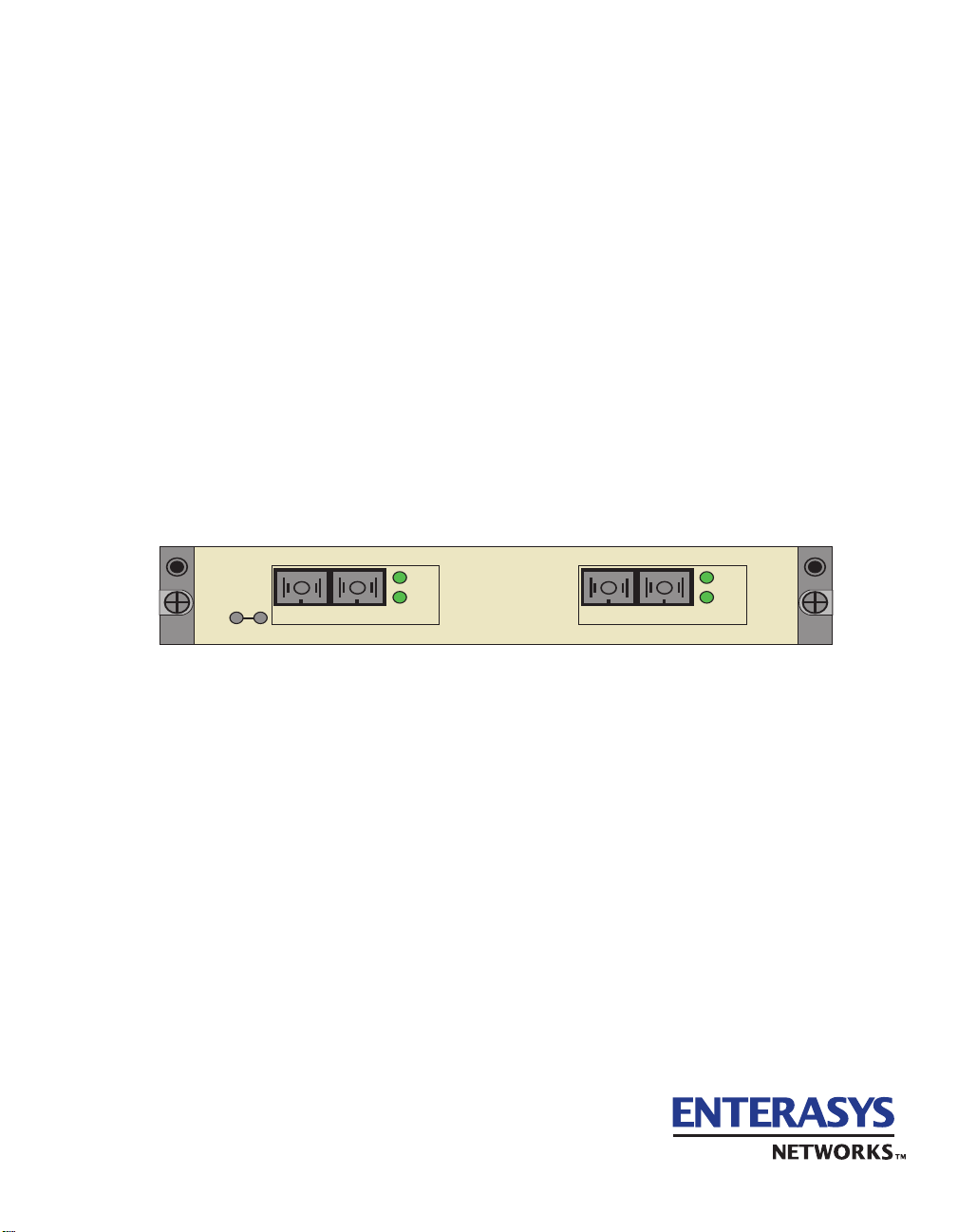
VHSIM2-A6DP
User’s Guide
APIM 1 APIM 2
STS
LNK
APIM-21R
VHSIM2-A6DP
STS
LNK
APIM-21R
9032825-02
Page 2

Page 3

ELECTRICAL HAZARD: Only qualified personnel should perform installation
procedures.
NOTICE
Enterasys Networks and its lic ensors reserv e t he right to ma ke cha nges in specifications and other information contained
in this document without prior notice. The reader should in all cases consult Enterasys Networks to determine whether
any such changes have been made.
The hardware, firmware, or software described in this manual is subject to change without notice.
IN NO EVENT SHALL ENTERASYS NETWORKS AND ITS LICENSORS BE LIABLE FOR ANY INCIDENTAL, INDIRECT,
SPECIAL, OR CONSEQUENTIAL DAMAGES WHATSOEVER (INC LUD ING BUT NOT LIMITED TO LOST PROFITS)
ARISING OUT OF OR RELATED TO THIS MANUAL OR THE INFORMATION CONTAINED IN IT, EVEN IF ENTERASYS
NETWORKS AND ITS LICENSORS HAVE BEEN ADVISED OF, KNOWN, OR SHOULD HAVE KNOWN, THE POSSIBILITY
OF SUCH DAMAGES.
Enterasys Networks, Inc.
35 Industrial Way
Rochester, NH 03866-5005
Enterasys Networks, Inc. is a subsidiary of Cabletron Systems, Inc.
2000 by Enterasys Networks , Inc.
All Rights Reserved
Printed in the United States of America
Order Number: 9032825-02 August 2000
LANVIEW and SecureFast are registered trademarks of Enterasys Networks or its licensors; HSIM, SmartSwitch,
APIM and Enterasys Networks are trademarks of Enterasys Networks or its licensors. SPECTRUM is a registered
trademark of Aprisma Management Technologies or its licensors.
All other product names mentioned in this manual may be trademarks or registered trademarks of their respective
companies.
i
Page 4

FCC NOTICE
This device complies with P art 15 of th e FCC rul es. Ope rat ion is sub ject to th e following two conditions: (1) this device
may not cause harmful interference, and (2) this device must accept any interference received, including interference that
may cause unde s i re d operation.
NOTE: This equipment has been tested and found to comply with the limits for a Class A digital device, pursuant to
Part 15 of the FCC rules. These limits are designed to provide reasonable protection against harmful interference whe n
the equipment is operated in a commercial environment. This equipment uses, generates, and can radiate radio frequency
energy and if not instal led in accordance with the operator’s manual, may cause harmful interference to radio
communications. Operation of this equipment in a residential area is likely to cause interference in which case the user
will be required to correct the interference at his own expense.
WARNING: Changes or modifications made to this device which are not expressly approved by the party responsible
for compliance could void the user’s authority to operate the equ ip ment.
INDUSTRY CANADA NOTICE
This digital apparatus does not exceed the Class A limits for radio noise emissions from digital apparatus set out in the
Radio Interference Regulations of the Canadian Department of Communications.
Le présent appareil numérique n’émet pas de bruits radioélectriques dépassant les limites applicables aux appareils
numériques de la class A prescrites dans le Règlement sur le brouillage radioélectrique édicté par le ministère des
Communications du Canada.
VCCI NOTICE
This is a Class A product based on the standard of the Voluntary Control Council for Interference by Information
Technology Equipment (VCCI). If this equipment is used in a domestic environment, radio disturbance may arise. When
such trouble occurs, the user may be required to take co rrective actions.
ii
Page 5

ENTERASYS NETWORKS, INC.
PROGRAM LICENSE AGREEMENT
BEFORE OPENING OR UTILIZING THE ENCLOSED PRODUCT,
CAREFULLY READ THIS LICENSE AGREEMENT.
This document is an agreement (“Agreement”) between You, the end user, and Enterasys Networks, Inc. (“Enterasys”)
that sets forth your rights and obligations with respect to the Enterasys software program (“Program”) in the package.
The Program may be contained in firmware, chips or other media. UTILIZING THE ENCLOSED PRODUCT, YOU
ARE AGREEING TO BECOME BOUND BY THE TERMS OF THIS AGREEMENT, WHICH INCLUDES THE
LICENSE AND THE LIMITATION OF WARRANTY AND DISCLAIMER OF LIABILITY. IF YOU DO NOT
AGREE TO THE TERMS OF THIS AGREEMENT, RETURN THE UNOPENED PRODUCT TO ENTERASYS OR
YOUR DEALER, IF ANY, WITHIN TEN (10) DAYS FOLLOWING THE DATE OF RECEIPT FOR A FULL
REFUND.
IF YOU HAVE ANY QUESTIONS ABOUT THIS AGREEMENT, CONTACT ENTERASYS NETWORKS
(603) 332-9400. Att n: Legal Department.
1. LICENSE. You have the right to use only the one (1) copy of the Program provided in this package subject to the
terms and conditions of this License Agreement.
You may not copy, reproduce or transmit any part of the Program except as permitted by the Copyright Act of the
United States or as authorized in writing by Enterasys.
2. OTHER RESTRICTIONS. You may not reverse engineer, decompile, or disassemble the Program.
3. APPLICABLE LAW. This License Agreement shall be int erpreted and governed under the laws and in the state
and federal courts of New Hampshire. You accept the personal jurisdiction and venue of the New Hampshire courts.
4. EXPORT REQUIREMENTS. You understand that Enterasys and its Affiliates are subject to regulation by
agencies of the U.S. Government, includ ing the U.S. Department of Commerce, which prohibit export or dive rsion of
certain technical pro ducts to certain countrie s, unless a license to expo rt the product is obta ined from the U.S. Gove rnment
or an exception fro m obtaining such license may be relied upon by the exporting party.
If the Program is exported from the United States pursuant to the License Exception CIV under the U.S. Export
Administration Regulations, You agree that You are a civil end user of the Program and agree that You will use the
Program for civil end uses only and not for milita ry pu rpo se s.
If the Program is exported from the United States pursuant to the License Exception TSR under the U.S. Export
Administration Regulations, in addition to the restriction on transfer set forth in Sections 1 or 2 of this Agreement, You
agree not to (i) reexport or release the Program, the source code for the Program or technology to a national of a country
in Country Groups D:1 or E:2 (Albania, Armenia, Azerbaijan, Belarus, Bulgaria, Cambodia, Cuba, Estonia, Georgia,
Iraq, Kazakhstan, Kyrgyzstan, Laos, Latvia, Libya, Lithuania, Moldova, North Korea, the People’s Republic of China,
Romania, Russia, Rwanda, Tajikistan, Turkmenistan, Ukraine, Uzbekistan, Vietnam, or such other countries as may be
designated by the United States Government), (ii) export to Country Groups D:1 o r E:2 (as defined herein) the di rect
product of the Program or th e te chn olo g y, if such foreign produced direct p rod uc t is su bjec t to na tio n al securi ty c o ntro ls
as identified on th e U.S. Commerc e Contro l List, or (iii) if the d irect pro duct o f the te chnolog y is a c omplete plant o r an y
major component of a pl ant, export to Country Groups D:1 or E:2 the dir ect product of the plant or a major component
thereof, if such foreign produced di re ct product is subject to national security controls as identified on the U.S.
Commerce Control List or is subject to State Department controls under the U.S. Munitions List.
iii
Page 6

5. UNITED STATES GOVERNMENT RESTRICTED RIGHTS. The enclosed Product (i) was developed solely
at private expense; (ii) contains “re stricted computer software” submitte d with restricted rights in accordance with section
52.227-19 (a) through (d) of the Commercial Computer Software-Restricted Rights Clause and its successors, and (iii) in
all respects is proprietary data b e lon ging to En terasys an d/ or i ts sup pli ers. Fo r Departm ent o f De fe nse un its, the Pr od uc t
is considered commercial computer software in accordance with DFARS section 227.7202-3 and its successors, and use,
duplication, or disclosure by the Government is subject to restrictions set forth herein.
6. EXCLUSION OF WARRANTY. Except as may be specifically provided by Enterasys in writing, Enterasys
makes no warranty, expressed or implied, concerning the Program (including its do cumentation and media).
ENTERASYS DISCLAIMS ALL WARRANTIES, OTHER THAN THOSE SUPPLIED TO YOU BY
ENTERASYS IN WRITING, EITHER EXPRESS OR IMPLIED, INCLUDING BUT NOT LIMITED TO IMPLIED
WARRANTIES OF MERCHANTABILITY AND FITNESS FOR A PARTICULAR PURPOSE, WITH RESPECT TO
THE PROGRAM, THE ACCOMPANYING WRITTEN MATERIALS, AND ANY ACCOMPANYING HARDWARE.
7. NO LIABILITY FOR CONSEQUENTIAL DAMAGES. IN NO EVENT SHALL ENTERASYS OR ITS
SUPPLIERS BE LIABLE FOR ANY DAMAGES WHATSOEVER (INCLUDING, WITHOUT LIMITATION,
DAMAGES FOR LOSS OF BUSINESS, PROFITS, BUSINESS INTERRUPTION, LOSS OF BUSINESS
INFORMATION, SPECIAL, INCIDENTAL, CONSEQUENTIAL, OR RELIANCE DAMAGES, OR OTHER LOSS)
ARISING OUT OF THE USE OR INABILITY TO USE THIS E NTERASYS PRODUCT, EVEN IF ENTERASYS HAS
BEEN ADVISED OF THE POSSIBILITY OF SUCH DAMAGES. BECAUSE SOME STATES DO NOT ALLOW THE
EXCLUSION OR LIMITATION OF LIABILITY FOR CONSEQUENTIAL OR INCIDENTAL DAMAGES, OR IN
THE DURATION OR LIMITATION OF IMPLIED WARRANTIES IN SOME INSTANCES, THE ABOVE
LIMITATION AND EXCLUSIONS MAY NOT APPLY TO YOU.
iv
Page 7

SAFETY INFORMATION
CLASS 1 LASER TRANSCEIVERS
THE APIM-29, APIM-29LR, VAPIM-39, AND VAPIM-39LR ARE ATM PORT
INTERFACE MODULES THAT USE CLASS 1 LASER TRANSCEIVERS.
READ THE FOLLOWING SAFETY INFORMATION BEFORE
INSTALLING OR OPERATING THESE MODULES.
The Class 1 laser transceivers use an optical feedback loop to maintain Class 1 operation limits. This control loop
eliminates the need for maintenance checks or adjustments. The output is factory set, and does not allow any user
adjustment. Class 1 laser transceivers comply with the following safety standards:
• 21 CFR 1040.10 and 1040.11 U. S. Department of Health and Human S erv ic es (FDA).
• IEC Publication 825 (International Electrotechnical Commission).
• CENELEC EN 60825 (European Committee for El ec tro technical Standardization).
When operating within their performance limitations, laser transceiver output meets the Class 1 accessible emission limit
of all three standards. Class 1 levels of laser radiation are not considered hazardous.
SAFETY INFORMATION
CLASS 1 LASER TRANSCEIVERS
LASER RADIATION AND CONNECTORS
When the connector is in place, all laser radiation remains within the fiber. The maximum amount of radiant power
exiting the fiber (under normal conditions) is -12.6 dBm or 55 x 10
Removing the optical connector from the transceiver allows laser radiation to emit directly from the optical port. The
maximum radiance from the optical port (under worst case conditions) is
0.8 W cm
Do not use optical instruments to view the laser output. The use of optical instruments to view laser output
increases eye hazard. When viewing the output optical port, power mu st be removed from the network adapter.
-2
or 8 x 10³ W m2 sr-1.
-6
watts.
v
Page 8

DECLARATION OF CONFORMITY
Application of Council Directive(s): 89/336/EEC
73/23/EEC
Manufacturer’s Name: Enterasys Networks, Inc.
Manufacturer’s Address: 35 Industrial Way
PO Box 5005
Rochester, NH 03867
European Representative Name: Mr. Jim Sims
European Representative Address: Enterasys Networks Ltd.
Nexus House, Newbury Business Park
London Road, Newbury
Berkshire RG14 2PZ, England
Conformance to Directive(s)/Product Standards: EC Directive 89/336/EEC
EC Directive 73/23/EEC
EN 55022
EN 55024
EN 60950
EN 60825
Equipment Type/Environment: Netwo rking Equipment, for use in a Commercial
or Light Industrial Environment.
We the undersigned, hereby declare, under our sole responsibility, that the equipment packaged with this
notice conforms to the above directives.
Manufacturer Legal Representative in Europe
Mr. Tom Whissel Mr. Jim Sims
___________________ ________________ ___________________ ________________
Full Name Full Name
Compliance Engineering Manager President - E.M.E.A.
___________________ ________________ ___________________ ________________
Title Title
Rochester, NH, USA Newbury, Berkshire, England
___________________________________ ___________________________________
Location Location
vi
Page 9

Contents
Figures ............................................................................................................................................ x
Tables.............................................................................................................................................xii
ABOUT THIS GUIDE
Who Should Use This Guide.........................................................................................xiii
Structure of this Guide ..................................................................................................xiii
Related Manuals ...........................................................................................................xiv
1
2
3
INTRODUCTION
1.1 Overview.........................................................................................................1-1
1.1.1 ATM Port Interface Modules (APIMs and VAPIMs).........................1-2
1.1.2 MIB Support.....................................................................................1-2
1.1.3 LANVIEW Diagnostic LEDs.............................................................1-2
1.2 Getting Help ....................................................................................................1-3
INSTALLATION
2.1 Unpacking the VHSIM2-A6DP........................................................................2-1
2.2 Installing APIMs ................. ............................................. ....... .........................2-2
2.3 Installing VAPIMs................................................................... ...... ...................2-5
2.4 Installing a VHSIM............................................... ...... ......................................2-8
2.4.1 Installing a VHSIM2-A6DP in an Interface Module..........................2-8
2.4.2 Installing a VHSIM2-A6DP in a Standalone Device ............ ...... ....2-1 1
LOCAL MANAGEMENT
3.1 Using Local Management Screens.................................................................3-2
3.1.1 Local Management Screen Elements..............................................3-2
3.1.2 Local Management Keyboard Conventions.....................................3-5
3.1.3 Navigating Local Management Screens..........................................3-6
3.1.3.1 Selecting Local Management Menu Screen Items..........3-6
3.1.3.2 Exiting Local Management Screens................................3-7
Contents vii
Page 10

3.2 Accessing the VHSIM2-A6DP ATM Screen....................................................3-8
3.3 ATM Connections Screen ......................................... ...... ...... ....... ...... ....... ....3-10
3.4 ATM Connection Setup Screen.....................................................................3-11
3.5 Traffic Management PVC Priority Assignments............................................3-14
3.5.1 Adding Traffic Management PVC Priority Assignments ................3-17
3.5.2 Modifying an Entry (Vport).............................................................3-19
3.5.3 Deleting an Entry (Vport) ...............................................................3-19
3.5.4 Traffic Management PVC Priority Assignments Screen Example.3-20
3.6 Add/Delete Entry Screen...............................................................................3-21
3.6.1 Adding an Entry (PVC) ..................................................................3-22
3.6.2 Modifying an Entry (PVC)..............................................................3-23
3.6.3 Deleting an Entry (PVC) ................................................................3-23
3.7 ATM Connection Setup By Virtual Interface Screen .....................................3-24
3.7.1 Selecting a Virtual Interface...........................................................3-26
3.8 Physical Port Configuration Menu Screen ....................................................3-27
3.9 Port Framer Configuration Screen ........................................ ....... ...... ...........3-28
3.9.1 Configuring an APIM .....................................................................3-30
3.10 ATM Port Redundancy Configuration Screen........... ...... ...... ....... ...... ...........3-30
3.10.1 Setting the Redundancy Status.....................................................3-33
3.10.2 Setting the Primary Port ................................................................3-33
3.10.3 Setting the Active Port...................................................................3-34
3.10.4 Setting the Activation of Redundant Port Field..............................3-34
3.10.5 Setting the Revert to Primary Port Field........................................3-34
3.10.6 Setting the Periodic Test Status Field ...........................................3-35
3.10.7 Setting the Periodic Test Time ......................................................3-35
3.10.8 Using the TEST PORTS NOW Command ....................................3-36
3.10.9 Using the RESET TO FACTORY DEFAULTS Command.............3-36
3.11 LAN Emulation Clients Screen......................................................................3-36
3.12 LEC Table Screen.........................................................................................3-38
3.13 LEC Administration Screen...........................................................................3-40
3.13.1 Changing the LEC Status of an Existing LEC ...............................3-44
3.13.2 Configuring a New LEC Automatically...........................................3-44
3.13.3 Configuring a New LEC Manually..................................................3-45
3.13.4 Modifying an Existing LEC.............................................................3-47
3.13.5 Deleting an Existing LEC...............................................................3-48
3.14 LEC Properties Screen .................................................................................3-48
3.14.1 Viewing Multiple ELANs ................................................................3-51
3.15 LEC ARP Cache Screen...............................................................................3-52
3.15.1 Performing a Search......................................................................3-54
3.16 LEC Priority Queues Screen.........................................................................3-54
3.16.1 Assigning Priorities to a LEC.........................................................3-56
viii Contents
Page 11

3.17 Signalling Screen ..........................................................................................3-57
3.17.1 Changing the UNI Version.............................................................3-59
3.17.2 Changing the ILMI Status to Disabled...........................................3-59
3.17.3 Changing the UNI Status...............................................................3-60
3.17.4 Restarting UNI.............................. ....... ...... ...... ....... ...... ....... ...... ....3-60
3.17.5 Restarting the ILMI .......................................... ....... ...... ....... ...... ....3-60
3.18 Traffic Management Screen..........................................................................3-61
3.18.1 Setting up a Descriptor Profile.......................................................3-63
3.18.2 Modifying a Descriptor Profile........................................................3-63
3.18.3 Deleting a Descriptor Profile..........................................................3-63
3.19 Discovery ELAN Setup Screen.....................................................................3-64
3.19.1 Assigning the VHSIM2-A6DP to a Discovery ELAN......................3-66
4
A
B
INDEX
LANVIEW LEDS
4.1 VHSIM2-A6DP LEDs ......................................................................................4-1
VHSIM2-A6DP SPECIFICATIONS
A.1 Specifications..................................................................................................A-1
APIM AND VAPIM SPECIFICATIONS
B.1 APIM-21 Specifications...................................................................................B-1
B.2 APIM-29 Specifications...................................................................................B-2
B.3 APIM-29LR Specifications ..............................................................................B-3
B.4 APIM-22 Specifications...................................................................................B-4
B.5 APIM-67 Specifications...................................................................................B-5
B.6 VAPIM-31 Specifications..................................... ...... ...................................... B - 7
B.7 VAPIM-39 Specifications..................................... ...... ...................................... B - 8
B.8 VAPIM-39LR Specifications............................................................................B-9
Contents ix
Page 12

Figures
Figure Page
1-1 VHSIM2-A6DP ................................................................................................................1-1
2-1 Removing the APIM Coverplate......................................................................................2-3
2-2 Installing an APIM ...........................................................................................................2-4
2-3 Removing the APIM Coverplate......................................................................................2-6
2-4 Installing a VAPIM...........................................................................................................2-7
2-5 Removi ng the VHSIM Coverpla te ................................ ...... ....... ...... ...... ....... ...... ....... ......2 -9
2-6 Installing the VHSIM2-A6DP .........................................................................................2-10
3-1 Example of a Local Management Screen .......................................................................3-3
3-2 VHSIM2-A6DP Local Management Screen Hierarchy....................................................3-6
3-3 VHSIM2-A6DP ATM Screen ...........................................................................................3-8
3-4 ATM Connectio ns Screen ..................................... ....... ...... ....... ....................................3-10
3-5 ATM Connection Setup Screen.....................................................................................3-11
3-6 Traffic Management PVC Priority Assignments Screen................................................3-14
3-7 Example Traffic Management PVC Priority Assignments Screen.................................3-20
3-8 Add/Delete Entry Screen...............................................................................................3-21
3-9 ATM Connection Setup By Virtual Interface Screen .....................................................3-24
3-10 Physical Port Configuration Menu Screen.....................................................................3-27
3-11 Port Framer Config urati on Scre en ..................................... ...........................................3-28
3-12 ATM Port Redunda ncy Configurat ion Screen .................... ....... ....................................3-31
3-13 LAN Emulation Clients Screens Menu..........................................................................3-37
3-14 LEC Table Screen.........................................................................................................3-38
3-15 LEC Administration Screen ...........................................................................................3-40
3-16 LEC Properties Screen..................................................................................................3-49
3-17 LEC ARP Cache Screen ...............................................................................................3-52
3-18 Traffic Managment LEC Priority Queues Screen ..........................................................3-55
3-19 Signalling Screen ..........................................................................................................3-57
3-20 Traffic Management Descriptor Profiles Screen............................................................3-61
3-21 ATM Discovery ELAN Setup Screen.............................................................................3-65
4-1 VHSIM2-A6DP and APIM/VAPIM LEDs..........................................................................4-1
B-1 APIM-21..........................................................................................................................B-1
B-2 APIM-29..........................................................................................................................B-2
B-3 APIM-29LR......................................................................................................................B-3
B-4 APIM-22 Pin Assignments...............................................................................................B-4
B-5 APIM-67R Default Jumper Settings ................................................................................B-6
B-6 APIM-67..........................................................................................................................B-6
x Figures
Page 13

B-7 VAPIM-31........................................................................................................................B-7
B-8 VAPIM-39........................................................................................................................B-8
B-9 VAPIM-39LR...................................................................................................................B-9
Figures xi
Page 14

Tables
Table Page
3-1 Event Messages...........................................................................................................3-4
3-2 Keyboard Conventions .................................................................................................3-5
4-1 VHSIM2-A6DP LEDs....................................................................................................4-2
4-2 APIM LEDs...................................................................................................................4-2
xii Tables
Page 15

About This Guide
Welcome to the Enterasys Networks VHSIM2-A6DP User’s Guide. This manual provides the
following information:
• Describes VHSIM2-A6DP features
• Expla ins ho w to inst all the VHSIM2- A6DP in Enteras ys interf ace modul e or standalon e de vice
• Outlines specificatio ns for the Enterasys Asynchronous Transfer Mode (ATM) Very High
Speed Interface Module (VHSIM)
The VHSIM2-A6DP provides additional connectivity/functionality to various Enterasys interface
modules and standalone devices by providing redundant uplinks to networks using Asynchronous
Transfer Mode (ATM).
WHO SHOULD USE THIS GUIDE
This guide is for Enterasys service personnel and qualified customer maintenance personnel who
are familiar with installing networking systems and have a working knowledge of ATM networks
and LAN Emulation, and for system managers and others who perform network management
tasks.
STRUCTURE OF THIS GUIDE
Read through this guide completely to familiarize yourself with its content and to gain an
understanding of the features and capabilities of the VHSIM2-A6DP.
This guide is organized as follows:
Chapter 1, Introduction, outlines the contents of this manual, describes VHSIM2-A6DP features
and concludes with a list of related manuals.
Chapter 2, Installation, describes how to install ATM Port Interface Modules (APIMs and
VAPIMs) into the VHSIM2-A6DP. This chapter also explains how to install a VHSIM2-A6DP
into an interface module or a standalone device.
Chapter 3, Local Management, describes how to use the VHSIM2-A6DP Local Management
screens to configure the VHSIM2-A6DP for connection to an ATM network.
xiii
Page 16

Related Manuals
Chapter 4, LANVIEW LEDs, describes ho w t o use th e VHSIM2-A6DP LEDs to moni tor VHSIM
performance and status.
Appendix A, VHSIM2-A6DP Specifications, describes environmental specifications and safety
requiremen ts for the VHSIM 2-A6DP.
Appendix B, APIM and VAPIM Specifications, describes specifications and features for each of
the APIMs and VAPIMs available for the VHSIM2-A6DP.
RELATED MANUALS
Use the following Enterasys Networks manuals to supplement the procedures and other technical
data provided in this manual.
• ATM Technology Guide
• Cabling Guide
NOTE: The documentation for the interface module or standalone device in which the
VHSIM2-A6DP will be installed will also assist you in the installation and setup of the
VHSIM2-A6DP.
The manuals reference d abov e can be obtai ned on the World Wide Web in Adobe Acrobat Portabl e
Document Format (PDF) at the following site:
http://www.enterasys.com/
NOTE: For additional information on ATM technology, visit the ATM Forum’s web site at
www.atmforum.com
All documentation for SecureFast VLAN Manager software can be found on the VLAN
Manager CD-ROM.
xiv
Page 17
DOCUMENT CONVENTIONS
The following conventions are used throughout this document:
NOTE: Calls the reader’s attention to any item of information that may be of special
importance.
TIP: Conveys helpful hints concerning procedures or actions.
CAUTION: Contains information essential to avoid damage to the equipment.
ELECTRICAL HAZARD: Warns against an action that could result in personal injury or
death due to an electrical hazard.
Related Manuals
bold type Bold type denotes text that the user should highlight or input on a screen. Bold type is also
used for emphasis and cross references to other sections and titles of this manual.
RETURN Indicates either the ENTER or RETURN key, depending on your keyboard.
ESC Indicates the keyboard Escape key.
SPACE bar Indicates the keyboard space bar key.
BACKSPACE Indicates the keyboard backspace key.
arrow keys Refers to the four keyboard arrow keys.
[-] Indicates the keyboard – key.
DEL Indicates the keyboard delete key.
italic type Italic type emphasizes important information, indicates variables, and indicates titles of
referenced documents.
n.nn A period in numerals signals the decimal point indicator (e.g., 1.75 equals one and three
fourths).
xv
Page 18

Related Manuals
x A lowercase italic x indicates the generic use of a letter (e.g., xxx indicates any combination
of three alphabetic characters).
n A lowercase italic n indicates the generic use of a number (e.g., 19nn indicates a four-digit
number in which the last two digits are unknown).
[ ] In the Local Management screens, brackets indicate that a value may be entered or selected.
xvi
Page 19
Introduction
This chapter provides a brief overview of the VHSIM2-A6DP and provides information on
obtaining additional help from Enterasys Networks.
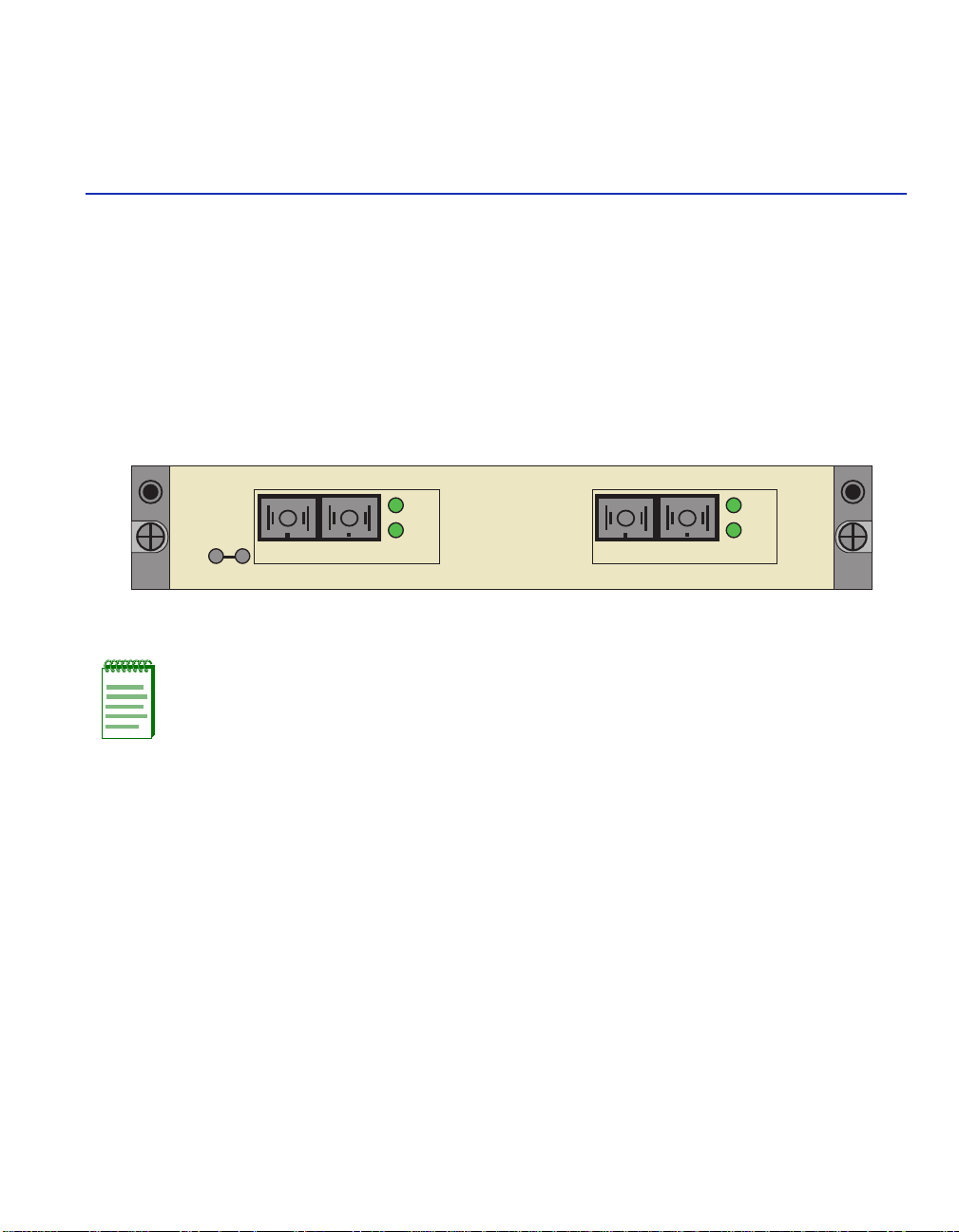
Figure 1-1 VHSIM2-A6DP
1
APIM 1 APIM 2
STS
LNK
APIM-21R
VHSIM2-A6DP
STS
LNK
APIM-21R
2825_01
NOTE: Unless noted otherwise, all Enterasys Networks APIMs and VAPIMs available
for the VHSIM2-A6DP are referred to as “APIMs” in this document.
1.1 OVERVIEW
The VHSIM2-A6DP extends the functionality of the Enterasys Networks interface module or
standalone device to include remote uplink capability. It allows remote connectivity using ATM
technology.
Two APIMs can be installed in the VHSIM2-A6DP to provide redundant ATM links from the
VHSIM2-A6DP to a switched ATM network. Enterasys Networks provides a variety of APIMs
that allow the user to select the type of configuration that best meets the network requirements. If
port redundancy is not a requirement, then only one APIM needs to be installed.
The VHSIM2-A6DP supports two types of Virtual Channels: Permanent Virtual Channels (PVCs),
and Switched Virtual Channels (SVCs), which are compliant with the ATM Foru m’s
User-Network-Interface (UNI 3.0, UNI 3.1 and UNI 4.0) for SVC signaling specification.
Introduction 1-1
Page 20

Overview
1.1.1 ATM Port Interface Modules (APIMs and VAPIMs)
The VHSIM2-A6DP supports two Enterasys Networks APIMs for ATM connectivity and
redundancy. APIMs for any in terface can be installed into the VHSIM2-A6DP. T he two APIMs
installed may be of an y co mb ina ti on of phy si cal layer cable type and bandwidth. For example, t he
APIM installed in slot 1 could support Twisted Pair cable and provide 155 Mbps of bandwidth,
while the APIM installed i n slot 2 could support Coaxi al cable and pro vide 45 Mbps of bandwidth.
Appendix B details all of the APIMs and VAPIMs available for the VHSIM2-A6DP.
1.1.2 MIB Support
For additional information on how to extract and compile individual MI Bs, refer to the Release
Notes, or contact Enterasys Networks for techn ical support. Refer to Section 1.2 for details.
1.1.3 LANVIEW Diagnostic LEDs
Enterasys Networks provides a visual diagnostic and monitoring system called LANVIEW. The
VHSIM2-A6DP LANVIEW LEDs help to quickly identify transmit/receive and link status.
1-2 Introduction
Page 21

Getting Help
1.2 GETTING HELP
For additional support related to the product or this document, contact Enterasys Networks using
one of the following methods:
World Wide Web http://www.enterasys.com/
Phone (603) 332-9400
Internet mail support@enterasys.c om
FTP ftp://ftp.entera sys .com
Login
Password
To send comments or suggestions concerning this document, contact the Technical Writing
Department via the following email address: TechWriting@enterasys.com
Make sure to include the document Part Number in the email message.
Before contacting Enterasys Networks, have the following information ready:
• Your Enterasys Networks service contract number
• A description of the failure
anonymous
your email address
• A description of any action(s) already taken to resolve the problem (e.g., changing mode
switches, rebooting the unit, etc.)
• The serial and revision numbers of all involved Enterasys Networks products in the network
• A description of your network environment (layout, cable type, etc.)
• Network load and frame size at the time of trouble (if known)
• The device history (i.e., have you returned the device before, is this a recurring problem, etc.)
• Any previous Return Material Authorization (RMA) numbers
Introduction 1-3
Page 22

Page 23

Installation
This chapter contains instructions for the following tasks:
• Unpacking the VHSIM2-A6DP (Section 2.1)
• Installing APIMs (Section 2.2)
• Installing a VHSIM2-A6DP (Section 2.4)
To install the VHSIM2-A6DP and APIMs, the following tools are required:
• Antistatic wrist strap (provided with the 6C105 chassis or standalone device)
• Phillips screwdriver
2.1 UNPACKING THE VHSIM2-A6DP
Unpack the VHSIM2-A6DP as follows:
CAUTION: The VHSIM2-A6DP and the host module or device are sensitive to static
discharges. Use an antistatic wrist strap and observe all static precautions during this
procedure. Failure to do so could result in damage to the VHSIM2-A6DP, the host
module, or device.
2
1. Remove the shipping box material covering the VHSIM2-A6DP.
2. Carefully remove the module from the shipping box. Leave the module in its non-conductive
bag until you are ready to install the module.
3. Attach the antist atic wrist strap (refer to the instructions on the antistatic wrist strap package).
4. After removing the module from its non-conductive bag, visually inspect the device. If you
notice any signs of damage, contact Enterasys Networks immediately. Refer to Section 1.2.
Installation 2-1
Page 24

Installing APIMs
2.2 INSTALLING APIMs
NOTE: To install VAPIMs, refer to Section 2.3.
ELECTRICAL HAZARD: Only qualified personnel should install or service this unit.
To install an APIM into the VHSIM2-A6DP, proceed as follows:
1. Attach the antistatic wrist strap (refer to the instruc t ions on the antistatic wrist strap package).
2. Remove and save the faceplate screws attaching the faceplate to the VHSIM2-A6DP. See
Figure 2-1. Remove the VHSIM2-A6DP faceplate.
3. Remove and save the three screws from the VHSIM2-A6DP standoffs. Remove the APIM
coverplate.
2-2 Installation
Page 25
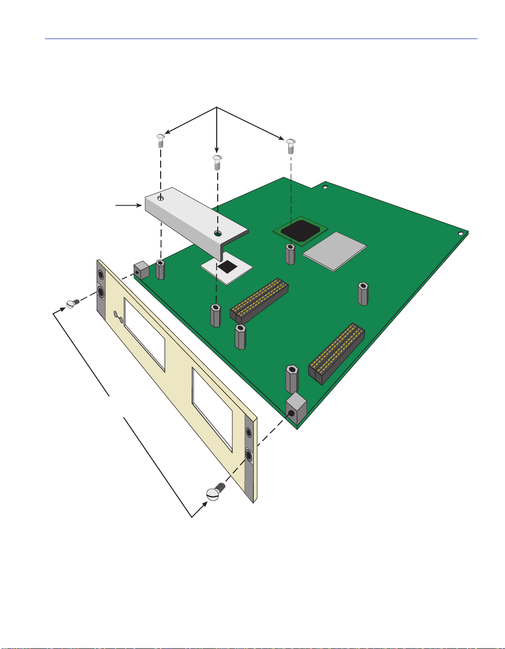
Figure 2-1 Removing the APIM Coverplate
Standoff
Screws
APIM
Coverplate
APIM 1 APIM 2
Installing APIMs
Faceplate
Screws
VHSIM2-A6DP
2825_02
Installation 2-3
Page 26
Installing APIMs
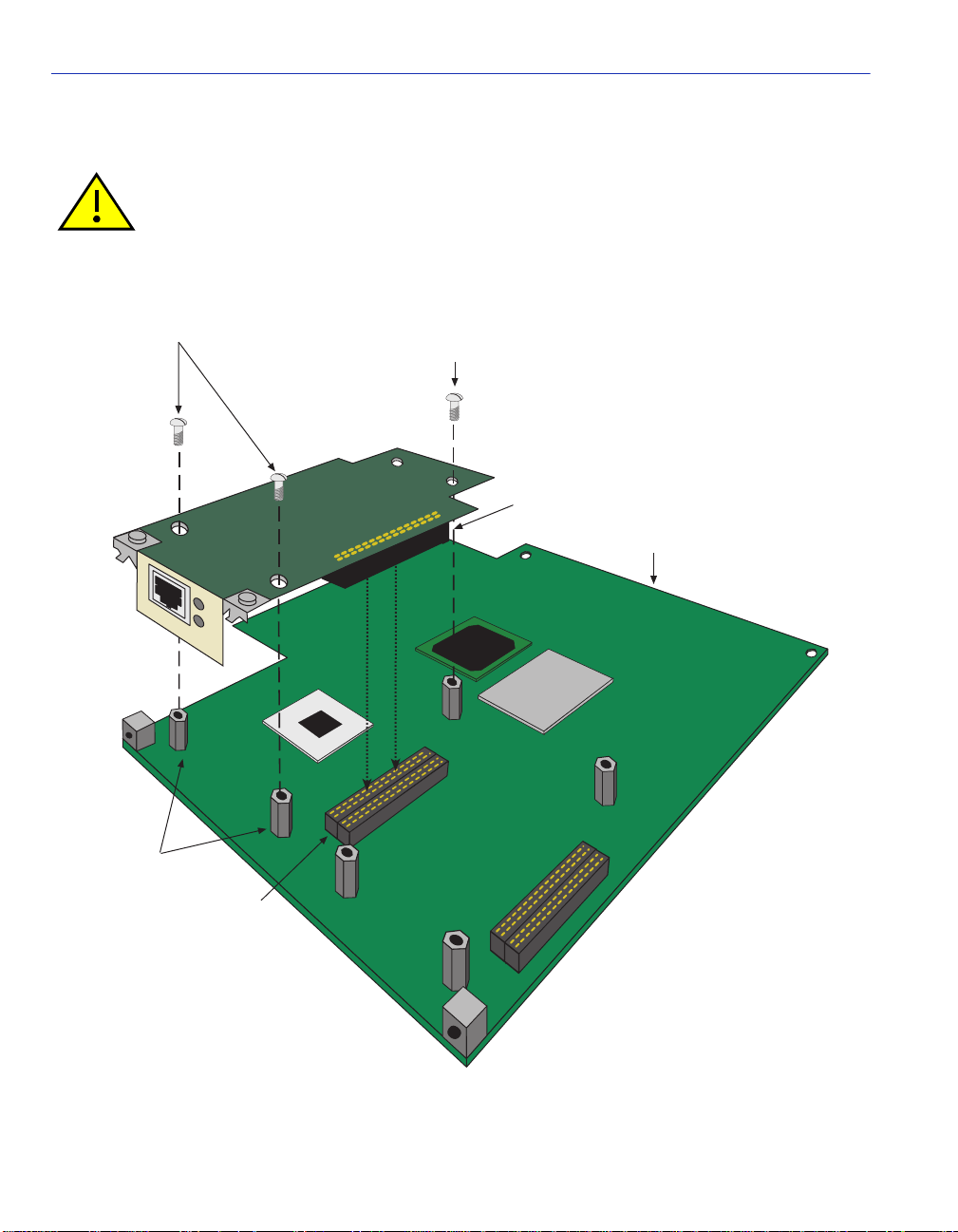
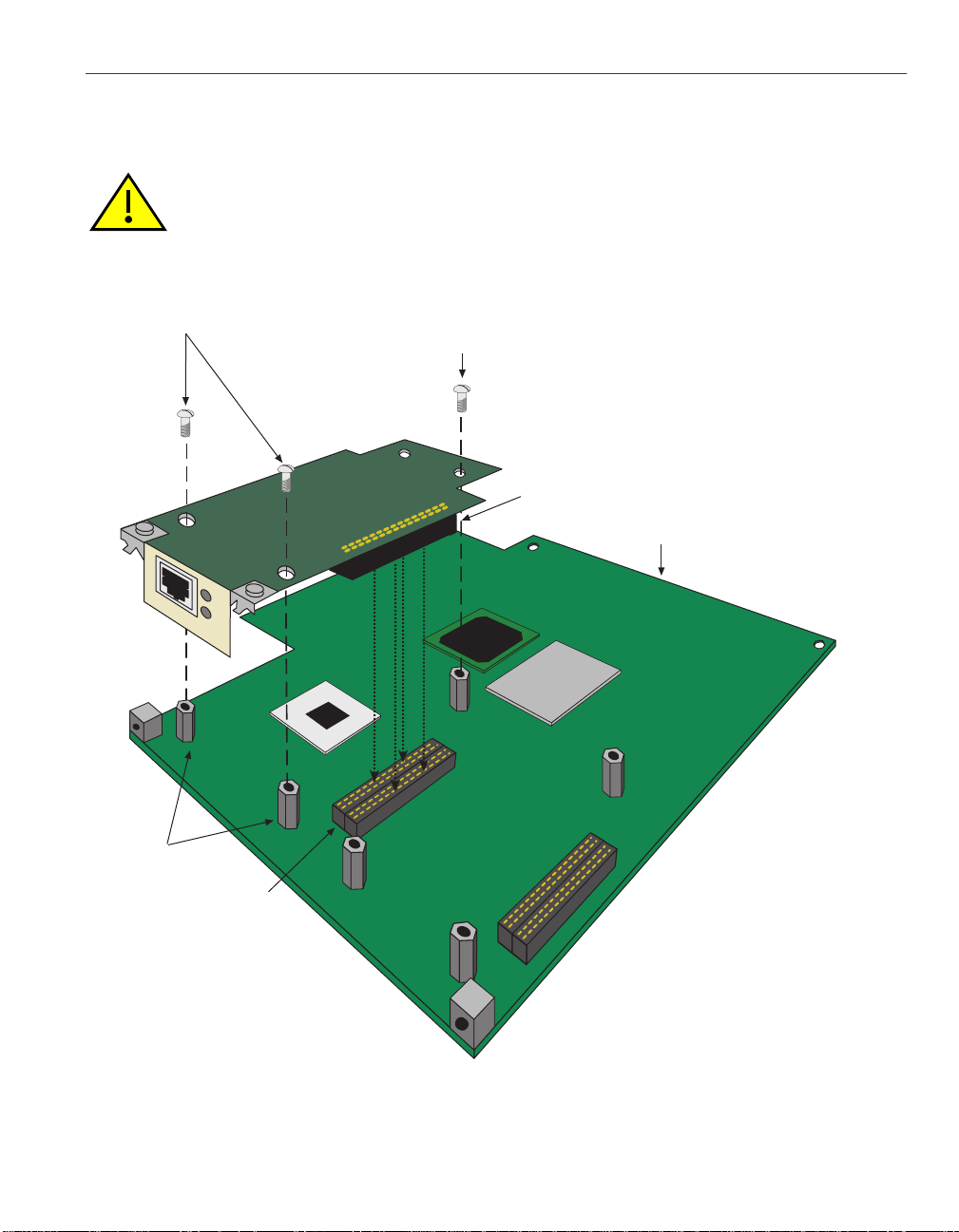
4. Align the APIM connector with the VHSIM2-A6DP connector pins as shown in Figure 2-2.
CAUTION: Ensure that the APIM connector aligns with the VHSIM2-A6DP connector
pins to prevent bending the pins. This can damage both the VHSIM2-A6DP and the
module.
Figure 2-2 Installing an APIM
APIM Screws
STS
LNK
Standoffs
Optional Third
APIM Screw
APIM Connector
VHSIM2
VHSIM2
Connector Pins
2-4 Installation
2825_03
Page 27

Installing VAPIMs
5. Press down firmly on the APIM until the pins slide all the way into the connector. Ensure the
APIM sits flush on the standoffs. If t he APIM do es not sit flush with the standoffs, ensu re t hat
the pins have been inserted into the correct connector on the VHSIM2-A6DP. Refer to
Figure 2-2.
6. Secure the APIM with the screws saved in step 3. The screw used to attach the rear of th e APIM
to the standoff is optional, and is not necessary for proper installation. Refer to Figure 2-2.
7. Reattach the faceplate to the VHSIM2-A6DP using the three screws saved in step 2.
2.3 INSTALLING VAPIMs
ELECTRICAL HAZARD: Only qualified personnel should install or service this unit.
To install a VAPIM into the VHSIM2-A6DP, proceed as follows:
1. Attach the antist atic wrist strap (refer to the instructions on the antistatic wrist strap package).
2. Remove and save the faceplate screws attaching the faceplate to the VHSIM2-A6DP. See
Figure 2-3. Remove the VHSIM2-A6DP faceplate.
3. Remove and save the three screws from the VHSIM2-A6DP standoffs. Remove the APIM
coverplate.
Installation 2-5
Page 28
Installing VAPIMs
Figure 2-3 Removing the APIM Coverplate
Standoff
Screws
APIM
Coverplate
APIM 1 APIM 2
Faceplate
Screws
2-6 Installation
VHSIM2-A6DP
2825_02
Page 29
Installing VAPIMs
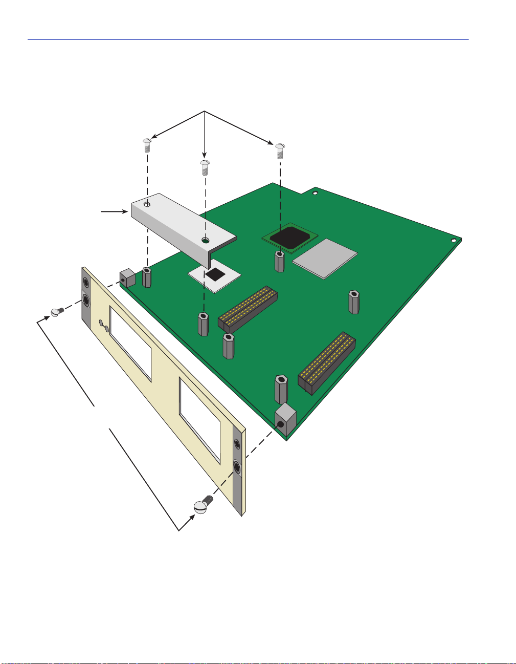
4. Align the VAPIM connectors into the VHSIM2-A6DP connectors as shown in Figure 2-4.
CAUTION: Ensure that the VAPIM connectors align with the VHSIM2-A6DP connectors
to prevent bending the pins. This can damage both the VHSIM2-A6DP and the module.
Figure 2-4 Installing a VAPIM
VAPIM Screws
STS
LNK
Standoffs
Optional Third
VAPIM Screw
VAPIM Connector
VHSIM2
VHSIM2
Connector Pins
2825_05
Installation 2-7
Page 30

Installing a VHSIM
5. Press down firmly on t he VAPIM until t he pins sl ide all the wa y into the c onnector. En sure the
VAPIM sits flush on the standoffs.
6. Secure the VAPIM with the screws saved in step 3. The screw used to attach the rear of the
VAPIM to the standoff is optional, a nd is not necessary for proper installation. Refer to
Figure 2-4.
7. Reattach the faceplate to the VHSIM2-A6DP using the three screws saved in step 2.
2.4 INSTALLING A VHSIM
ELECTRICAL HAZARD: Only qualified personnel should install or service this unit.
You can install a VHSIM in any Enterasys Networks device that supports VHSIM2-A6DP
technology (e.g., 2E252-25, 6E252-17). Refer to the release notes for the version of firmware
running on the Enterasys Networks device to ensure that the VHSIM2-A6DP is supported. The
following subsections pro vide generic i nstructions for installing an VHSIM2-A6DP in a module or
in a standalone device.
2.4.1 Installing a VHSIM2-A6DP in an Interface Module
To install an VHSIM2-A6DP in a module that supports VHSIM2-A6DP technology proceed as
follows:
1. Disconnect all cables from the interface module. Note the ports to which these cables attach.
2. Attach the antistatic wrist strap (refer to the instructions outlined on the antistatic wrist strap
package).
3. Unlock the top and bottom plastic locking tabs of the module faceplate.
4. Slide out the module, and place it on its side with the internal components facing up.
5. Remove and save the two faceplate mounting screws securing the VHSIM2-A6DP coverplate
and remove the coverplate. See Figure 2-5.
6. Remove and save the two standoff screws. See Figure 2-5.
2-8 Installation
Page 31
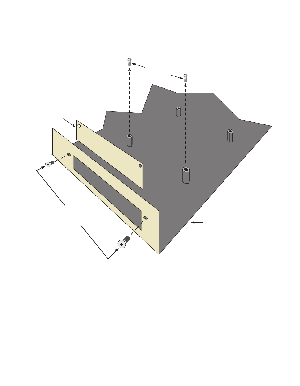
Figure 2-5 Removing the VHSIM Coverplate
Standoff
Screws
VHSIM2
Coverplate
Installing a VHSIM
Faceplate
Mounting
Screws
Host Device
2825_06
Installation 2-9
Page 32

Installing a VHSIM
Place the VHSIM behind the module faceplate. See Figure 2-6.
Figure 2-6 Installing the VHSIM2-A6DP
Standoff
Screws
APIM 1
STS
LNK
APIM 2
VHSIM2-A6DP
STS
LNK
VHSIM2
Connector
Host Device
Connector
Standoffs
Faceplate
Mounting
Screws
Host Device
2825_06
7. Align the connec tors of the VHSIM2- A6DP into the host dev ice connector pi ns on the module
as shown in Figure 2-6.
2-10 Installation
Page 33

Installing a VHSIM
CAUTION: Ensure that the VHSIM2-A6DP connectors align with the host device
connector pins to prevent bending the pins. This can damage both the VHSIM2-A6DP
and the module.
8. Press down firmly on the back of the VHSIM2-A6DP until the pins slide all the way into the
connector holes.
9. Secure the VHSIM2-A6DP to the faceplate using the two screws saved in step 5.
CAUTION: In step 10 ensure that the standoffs on the interface module align with the
standoff screw holes on the VHSIM2-A6DP to prevent bending the pins.
10. Secure the VHSIM2-A6DP to the standoffs with the two screws saved in step 6.
11. Reinstall the interface module in the chassis.
12. Reattach the network cabling to the interface module.
13. Refer to Chapter 3 for instructions on configuring the VHSIM2-A6DP using Local
Management.
2.4.2 Installing a VHSIM2-A6DP in a Standalone Device
To install a VHSIM2-A6DP into a standalone device that supports VHSIM2-A6DP technology,
perform the following steps:
1. Power down the device and remove the power cord.
2. Disconnect all cables from the device. Note the ports to which these cables attach.
ELECTRICAL HAZARD: Ensure that you remove the power cord and ONL Y the screws
required to remove the chassis cover. Failure to comply could result in an electric shock
hazard.
3. Attach the antist atic wrist strap (refer to the instructions outlined on th e antistatic wrist strap
package).
4. Remove the device chassis cover ( ref er to y our specific device documentation for ins tr uct ions
on removing the device chassis cover).
5. Remove and save the two faceplate mounting screws securing the VHSIM2-A6DP coverplate
and remove the coverplate as shown back in Figure 2-5.
6. Remove and save the two standoff screws as shown back in Figure 2-5.
Installation 2-11
Page 34

Installing a VHSIM
7. Place the VHSIM2-A6DP behind the device faceplate as shown back in Figure 2-6.
8. Insert the connectors of the VHSIM2-A6DP into the host device connector pins on the device.
CAUTION: In step 8, ensure that the standoffs on the device align with the standoff
screw holes on the VHSIM2-A6DP to prevent bending the pins.
9. Press down firmly on the back of the VHSIM2-A6DP until the pins slide all the way into the
connector holes.
10. Secure th e VHSIM2-A6D P to the faceplate using the screws saved i n step 5.
11. Secure the VHSIM2-A6DP to the standoffs using the screws saved in step 6.
ELECTRICAL HAZARD: Ensure that the chassis cover is in place before reconnecting
the power cord.
12. Reattach the chassis co ver to the devic e, reconne ct the powe r cord, and reconn ect th e device t o
your network.
13. Refer to Chapter 3 for instructions on configuring the VHSIM2-A6DP using Local
Management.
2-12 Installation
Page 35

Local Management
This chapter explains how to perform the following tasks:
• How to view current ATM connections.
• C onfigure Permanent Virtual Channels (PVCs).
• Configure LAN Emulation Clients (LECs).
• View Emulated LAN (ELAN) properties.
• Perform searches of the VHSIM2-A6DP LEC ARP Cache.
• Create traffic profiles that may be assigned to LECs and PVCs.
• Configure the APIMs installed in the VHSIM2-A6DP for redundancy.
• Configure operating parameters for Switched Virtual Channels (SVCs) and optional LAN
Emulation Services using Local Management.
• Enable and configure LANE Services, allowing the VHSIM2-A6DP to perform as a LAN
Emulation Configuration Server (LECS), LAN Emulation Server (LES), and a Broadcast and
Unknown Server (BUS).
3
NOTE: When installed, the VHSIM2-A6DP provides additional Local Management
features. These features are accessed by entering Local Management of the host
interface module or standalone device. Refer to the host device user’s guide to establish
a Local Management connection.
Some screens described in this chapter may not yet be supported by the
VHSIM2-A6DP. Refer to the Release Notes to verify which screens are supported.
Local Management 3-1
Page 36

Using Local Management Screens
The following must be completed before configuring the VHSIM2-A6DP through Local
Management:
• Installation of an APIM in the VHSIM2-A6DP. Refer to Chapter 2 for instructions.
• Installation of the VHSIM2-A6DP in the host interface module or standalone device with the
host device operational. Refer to Chapter 2 for instructions.
• Configuration and proper connection of a Local Management terminal to the host interface
module or standalone device in which the VHSIM2-A6DP resides.
3.1 USING LOCAL MANAGEMENT SCREENS
Section 3.1.1 through Section 3.1.3 describe Local Management screen ele m ent s, keyboard
conventions and how to navigate through the Local Management screens of the VHSIM2-A6DP.
3.1.1 Local Management Screen Elements
There are five types of screens used in Local Manage ment : password, menu, conf i gur at ion, status,
and warning screens. Each type of sc reen can con sist of one to f ive basic elements, or fields. Since
the top part of th e scre en conta in s the sa me type o f info rmat ion (t he name of th e scree n, the s wit ch
model number, the firmware revision, and the BOOT PROM revision), it is not shown in the
following descrip tions of the s creens. On ly th e lo wer port ion o f each sc reen is sho wn. The cuta way
line can be seen in Figure 3-1. The name of the screen is in the figure title for each screen.
Figure 3-1 shows an example of the fields in a screen. A description of each field follows the
figure.
NOTE: The following definitions apply to most Local Management screens. Exceptions
to these definitions may occur in the Local Management screens of some devices.
3-2 Local Management
Page 37

Figure 3-1 Example of a Local Management Screen
Event Message Field
Selection/Toggle
Fields
Display Field
Event Message Line
Device Name:XXXXX-XX
Slot Number:X
Redundancy Status: [Enabled]
Primary port: 1 Active port: 1
Activation of redundant port: [Automatic]
Revert to Primary port: [Automatic]
Periodic test status: [Enabled] Periodic test time: 01:00.00
Result of previous test: [ ] No test performed since system startup
TEST PORTS NOW RESET TO FACTORY DEFAULTS
XXXXX-XX LOCAL MANAGEMENT
Physical Interface 25 ATM Redundancy Configuration
Using Local Management Screens
Flash Image Revision: XX.XX.XX
BOOTPROM Revision: XX.XX.XX
RETURNSAVE EXIT
See Note
Input Field
NOTE:
This shows the location of the cut away that is used in most of the screen graphics in this document. The top portion on the screen is
cut away to eliminate repeating the same information in each graphic. The screen title is contained in its figure title.
Command Fields
28251_08
The following list explains each of the Local Management fields:
Event Message Field
This field briefly displays messages that indicate if a Local Management procedure was executed
correctly or incorrectly, that changes were saved or not saved to Non-Volatile Random Access
Memory (NVRAM), or that a user did not have access privileges to an application.
NOTE: Only the password, configuration and status screens have event message
fields.
Local Management 3-3
Page 38

Using Local Management Screens
Table 3-1 describes the most common event messages. Event messages related to specific Local
Management applications are described with those applications throughout this manual.
Table 3-1 Event Messages
Message What it Means
SAVED OK One or more fields were modified, and saved to NVRAM.
NOT SAVED--PRESS SAVE
TO KEEP CHANGES
Attempting to exit the LM screen after one or more fields
were modified, but not saved to NVRAM.
NOTHING TO SAVE The SAVE command was executed, but nothing was saved
to NVRAM.
Display Fields
Display fields cannot be edited. These fields may display information that never changes, or
information that may change as a result of Local Management operations, user selections and
configurations, or network monitoring information. In the screens shown in this guide, the
characters in the display fields are in plain type (not bold). In the field description, the field is
identified as being “read-only”.
Input Fields
Input Fields require the entry of keyboard characters. IP addresses, subnet mask, default gateway
and device time are examples of input fields. In the screens shown in this guide, the characters in
the input fields are in bold type. In the field description, the field is identified as being
“modifiable”.
Selection/Toggle Fields
Selection/Toggle fields provide a series of possible values. Only applicable values appear in a
selection field. In the screens shown in this guide, the selections display within brackets and in
bold type. In the f iel d descri ptio n, the f ield is ident ified as being either “selectable” when the re are
more than two possible values, or “toggle” when there are only two possible values.
Command Fields
Command fields are located at the bottom of Local Management screens. Command fields are
used to exit Local Management screens, save Local Management entries, or navigate to another
display of the same screen. In the screens shown in this guide, the characters in this field are all
upper case and in bold type. In the field description, the field is identified as being a “command”
field.
3-4 Local Management
Page 39

Using Local Management Screens
3.1.2 Local Management Keyboard Conventions
All key names appear in this manual as capital letters. For example, the Enter key appears as
ENTER and the Backspace key appears as BACKSPACE. Table 3-2 explains the keyboard
conventions used in this manual as well as the key functions.
Table 3-2 Keyboard Conventions
Key Function
ENTER Key and RETURN Key These are selection keys that perform the same Local
Management function. For example, “Press ENTER”
means that you can press either ENTER or RETURN,
unless this manual specifically instructs you otherwise.
SPACE Bar and BACKSPACE
Key
These keys cycle through selections in some Local
Management fields. U se the SPACE bar to cycle forward
through selections and use the BACKSPACE key to cycle
backward through selections.
Arrow Keys These are navigation keys. Use the UP-ARROW,
DOWN-ARROW, LEFT-ARROW, and RIGHT-ARROW
keys to move the screen cursor. For example, “Use the
arrow ke ys” means to press whi che ve r arro w ke y mov es the
cursor to the desired f ield on the Local Management screen.
Local Management 3-5
Page 40

Using Local Management Screens
3.1.3 Navigating Local Management Screens
The VHSIM2-A6DP Local Management appli cation consi sts of a series of menu screens. Na vigat e
through Local Management by selecting items from the menu screens. Figure 3-2 shows the
hierarchy of the VHSIM2-A6DP Local Management screens.
Figure 3-2 VHSIM2-A6DP Local Management Screen Hierarchy
CONNECTION
TABLE
ATM Connections
Screens
HSIM/VHSIM
Configuration
CONNECTIONS
ATM Screens
* The Discovery ELAN Setup Menu item will display only if the host device has been set to operate
as a SecureFast switch.
PHYSICAL PORT CONFIGURATION
LAN EMULATION CLIENTS
SIGNALLING
DISCOVERY ELAN SETUP *
TRAFFIC MANAGEMENT
CONNECTIONS BY VIRTUAL INTERFACE
PORT FRAMER CONFIGURATION
ATM PORT REDUNDANCY
LEC TABLE
LEC ADMINISTRATION
LEC PROPERTIES
LEC ARP CACHE
LEC TRANSMIT QUEUES
ATM CONNECTION SETUP
ADD/DELETE ENTRY
TRAFFIC MANAGEMENT
PVC PRIORITY ASSIGNMENTS
LEC ARP CACHE
3.1.3.1 Selecting Local Management Menu Screen Items
Select items on a menu screen by performing the following steps:
1. Use the arrow keys to highlight a menu item.
SEARCH
28251_09
2. Press ENTER. The selected Local Management screen displays.
3-6 Local Management
Page 41

Using Local Management Screens
3.1.3.2 Exiting Local Management Screens
There are two ways to exit Local Management (LM).
Using the EXIT Command
To exit an LM screen using the EXIT command, proceed as follows:
1. Use the arrow ke ys to highlight the EXIT command at the bottom of the Local Management
screen.
2. Press ENTER. The Password screen displays and the session ends.
Using the RETURN Command
1. Use the arrow ke ys to highlight the RETURN command at the bottom of the Local
Management screen.
2. Press ENTER. The previous screen in the Local Management hierarchy displays.
NOTE: The user can also exit Local Management screens by pressing ESC twice. This
exit method does not warn about unsaved changes and all unsaved changes will be
lost.
3. Exit from VHSIM2-A6DP Local Management by repeating steps 1 and 2 until the Main Menu
screen displays.
4. Use the arrow ke ys to highlight the RETURN command at the bottom of the Main Menu
screen.
5. Press ENTER. The Password screen displays and the session ends.
Local Management 3-7
Page 42

Accessing the VHSIM2-A6DP ATM Screen
3.2 ACCESSING THE VHSIM2-A6DP ATM SCREEN
To access the VHSIM2-A6DP ATM screen in a standalone device (e.g., 2E42-27), navigate
through the Local Mana gemen t scree ns until the High Spee d Conf i gurati on scr een d ispla ys. Sel ect
VHSIM2-A6DP CONFIGURATION from the High Speed Configuration screen and press
ENTER. The VHSIM2-A6DP ATM screen displays. See Figure 3-3.
To access the VHSIM2-A6DP ATM screen from an interface module (e.g., 6E132-25) navigate
through the Local Management screens until the Module Specific Configuration Menu screen
displays. Select HIGH SPEED CONFIGURATION from the Module Specific Menu scr een and
press ENTER. The VHSIM2-A6DP ATM screen displays. See Figure 3-3.
Figure 3-3 VHSIM2-A6DP ATM Screen
CONNECTIONS
PHYSICAL PORT CONFIGURATION
LAN EMULATION CLIENTS
SIGNALLING
TRAFFIC MANAGEMENT
DISCOVERY ELAN SETUP
EXIT
RETURN
28251_10
The VHSIM2-A6DP ATM screen displays up to six menu items for configuration and monitoring
of the VHSIM2-A6DP. The following list explains each of the VHSIM2-A6DP ATM screen
fields:
CONNECTIONS
This menu item opens the ATM Connections screen. This menu screen is used to view the current
configured virtual connections (PVCs and SVCs) of the VHSIM2-A6DP and to view the ATM
connections by virtual interface. The ATM Connections screen provides access to the Traffic
Management PVC Priority Assignments or the Add/Delete Entry screen, depending on the
operational mode of the device. These screens are used to add, modify, or delete PVCs. When the
operational mode of the device is set to 802.1Q, the Traffic Management PVC Priority
Assignments screen displays. When the operational mode of the device is set to SecureFast, the
Add/Delete Entry screen displays. For details, refer to Section 3.3.
3-8 Local Management
Page 43

Accessing the VHSIM2-A6DP ATM Screen
NOTE: The Add/Delete Entry screen will display only if the host device has been set
to operate as a SecureFast switch. Refer to the Local Management chapter of the host
device for instructions on configuring the host device for this type of operation.
PHYSICAL PORT CONFIGURATION
This menu item displays the Physical Port Configuration Menu screen. This screen provides two
menu items that allow the user to configure the physical ports of the VHSIM2-A6DP. For details,
refer to Section 3.8.
LAN EMULATION CLIENTS
This menu item displays the ATM LEC screen. This screen contains multiple options for
performing tasks related to the creation and maintenance of LAN Emulation Clients (LECs) and
Emulated LANs (ELANs). For details, refer to Section 3.11.
SIGNALLING
This menu item opens the Signalling screen. This screen is used to view the current version of
User-Network Interface (UNI) being used by the VHSIM2-A6DP, the current state of the
Integrated Loca l Management Interf a ce (ILMI) and provides the options of restarting the UNI and
the ILMI. For details, refer to Section 3.17.
TRAFFIC MANAGEMENT
This menu item opens the Traffic Management Descriptor Profiles screen. This screen is used to
create a ne w tr af fic descriptor, gi v e it a name, selec t a t raf fic category , a nd d esigna te th e tra ffic rate
for the new traffic descriptor. For details, refer to Section 3.18.
NOTE: The DISCOVERY ELAN SETUP menu item will display only if the host device
has been set to operate as a SecureFast switch. Refer to the Local Management
chapter of the host device for instructions on configuring the host device for this type of
operation.
DISCOVERY ELAN SETUP
This menu item opens the Disc ov ery ELAN Setup s creen, only when t he operat ional mode i s set to
SecureFast. This screen is used to enable or disable the default ELAN that is created when the
VHSIM2-A6DP is first initialized in SecureFast mode. This screen also is used to enable or disable
any additional discovery ELANs (up to 16) that the VHSIM2-A6DP will belong to on the
SecureFast network. For details, refer to Section 3.19.
Local Management 3-9
Page 44

ATM Connections Screen
3.3 ATM CONNECTIONS SCREEN
The ATM Connections screen allows the user to open the ATM Connections Setup scree n, an d t he
ATM Connection Setup by Virtual Interface screen.
To access the ATM Connections screen from the ATM screen, perform the following steps:
1. Use the ar row keys to h ighlight th e CONNECTIONS menu item of the VHSIM2-A6DP ATM
screen.
2. Press ENTER, the ATM Connections screen, Figure 3-4, displays.
Figure 3-4 ATM Connections Screen
CONNECTION TABLE
CONNECTIONS BY VIRTUAL INTERFACE
EXITSAVE
RETURN
2825_11
The following list explains each of the ATM Connections screen fields:
CONNECTION TABLE
This menu item opens the ATM Connection Setup screen. This screen is used to view all current
ATM connections. This screen also provides access to the Traffic Management PVC Priority
Assignments and the Add/Delete Entry screens, which allow the user to create, modify, or delete
PVCs. The Traffic Management PVC Priority Assignments screen is only available when the
device is c onfigured for 802.1Q. The Add/Delete Entr y screen is only available when the device is
configured for SecureFast. For the ATM Connection Setup screen, refer to Section 3.4.
NOTE: The Add/Delete Entry screen will display only if the host device has been set
to operate as a SecureFast switch. Refer to the Local Management chapter of the host
device for instructions on configuring the host device for this type of operation.
3-10 Local Management
Page 45

ATM Connection Setup Screen
CONNECTIONS BY VIRTUAL INTERFACE
This menu item, when s elected , opens th e ATM Connection S etup b y Virtual Interface screen. This
screen is used to view all current connections (PVCs and SVCs) on an interface-by-interface basis.
Refer to Section 3.7.
3.4 ATM CONNECTION SETUP SCREEN
The ATM Connection Setup screen is used to view the current configured virtual connections,
(PVCs and SVCs) on the VHSIM2-A6DP. This screen also allows the user to access the
Add/Delete Entry screen, which is used to create, modify, or delete PVCs.
To access the ATM Connection Setup screen from the ATM Connections screen, perform the
following st eps:
1. Use the arrow ke ys to highlight the CONNECTION TABLE menu item on the ATM
Connections screen.
2. Press ENTER. The ATM Connection Setup screen, Figure 3-5, displays.
Figure 3-5 ATM Connection Setup Screen
Total Bandwidth Available: 155 Mbps
ATM Port Current Connections: 30
VCI
VPI
PORT
0
25
25
31
32
34
36
38
40
0
0
0
1
0
1
0
1
0
1
0
1
0
1
0
Encapsulation Type
5
UNI
16
ILMI
25
LANE Control
26
LANE Control
998
LANE Control
999
LANE Control
1000
LANE Control
1001
VC Mux 802.3 Bdg
ATM Address (ESI)
00-00-1D-XX-XX-XX
00-00-1D-XX-XX-XX
00-00-1D-XX-XX-XX
00-00-1D-XX-XX-XX
00-00-1D-XX-XX-XX
00-00-1D-XX-XX-XX
TRAFFIC
CATEGORY
UBR
UBR
UBR
UBR
UBR
UBR
UBR
UBR
[Page 1 of 4]
RATEIF
155 Mbs
155 Mbs
155 Mbs
155 Mbs
155 Mbs
155 Mbs
155 Mbs
155 Mbs
RETURNADD/DELETE PREVIOUS NEXT EXIT
INDEX
1
1
1
1
1
1
1
1
28252_12
NOTE: The first two connections shown in Figure 3-5 (with VPI, VCI values of 0, 5 and
0, 16 respectively) represent UNI and ILMI. These two connections, even if they are
disabled in the Signalling screen (Section 3.17), will always display on the ATM
Connection Setup screen.
Local Management 3-11
Page 46

ATM Connection Setup Screen
The following list explains each of the ATM Connection Setup screen fields:
Total Bandwidth Available (Read-Only)
Shows the resources the current APIM has available for the assignment of PVCs and their
associated traffic descriptors. If there a re no PVCs co nfigured, the maximum bandwidth the active
APIM supports is displayed. For example, an APIM-21 will display 155 Mbps. As PVCs with
traffic descriptors are assigned, their rate is subtracted from the total.
ATM Port Current Connections (Read-Only)
Displays the number of current connections on the VHSIM2-A6DP.
IF (Read-Only)
Represents the vi rtua l MI B-II i nt erf ace on which t hi s Virtual Channel (VC) was cre ated. This f i eld
can represent both Switched Virtual Channels (SVCs ), and Permanent Virtual Channels (PVC s).
These virtu al MIB-II interfaces will also display o n the Switch Configuration screen of th e host
device. If the status of a PVC is down, an asterisk (*) appears to the left of the IF field next to the
PVC that is down, and the message “* Operational Status for the indicated connection(s) is
‘down’.” will appear at the bottom of the screen.
PORT (Read-Only)
Displays the application port on which the PVC or SVC resides. Once a PVC is created, it is
dynamically assigned a switch port number. This port number then may be assigned to an 802.1Q
or SecureFast VLAN, depending on the operational mode of the host device. If this connection is
an SVC, the switch port number is assigned to the LEC to which this SVC belongs. The UNI and
ILMI connections will display “0”.
VPI (Read-Only)
Displays the Virtual Path Identifier of the connecti on. This field re ads 0 or 1 (currently, only 0
and 1 are supported).
VCI (Read-Only)
Displays the Virtual Channel Identifier of the connection. This field reads between 32 and 4095.
Encapsulation Type (Read-Only)
Displays the type of Encapsulation being used to switch Ethernet frames to ATM cells. The three
possible op tions for this field are as follows:
• LANE - VC Based Multiplex ed 802.3 LAN Emulatio n. This method i s specif ied b y the ATM
Forum LAN Emulation specification. This option is available for SVCs only.
• VC Mux 802.3 Bdg - VC Based Multiplexing f or Bridge d Protoco ls as d efi ned b y the I ETF
RFC 1483. This encapsulation type is for PVCs only.
3-12 Local Management
Page 47

ATM Connection Setup Screen
• LLC Encapsulated - Logical Link Control for Bridged Protocols as defined by the IETF
RFC 1483. This encapsulation type is for PVCs only.
NOTE: UNI, ILMI and SecureFast connections display the following values in the
Encapsulation Type field:
UNI (User to Network Interface)
ILMI (Integrated Local Management Interface)
ATM VC SVC APP (SecureFast network connections)
ATM Address (ESI) (Read-Only)
Displays the MAC Address of the device to which the SVC or PVC is currently connected (End
System Indentifier). This identifies the devices with which the VHSIM2-A6DP is currently
communicating. The UNI and ILMI connections will not display any value in this field.
Traffic Category (Read-Only)
Displays the traffic category of the assigned index.
Rate (Read-Only)
Displays the traffic rate of of the assigned index, rounded to Mbps.
Index (Read-Only)
Displays the traffic index assigned to each specific PVC.
ADD/DELETE (Command)
Used to provide access to the Traffic Management PVC Priority Assignments or the Add/Delete
Entry screens, which are used to add, modify, or delete PVCs. If the device is in 802.1Q
operational mode, the Traffic Management PVC Priority Assignments screen will display when
the ADD/DELETE key is pressed. To access this screen, refer to Section 3.6. If the device is in
SecureFast mode, the Add/Delete Entry screen will display when the ADD/DELETE key is
pressed. To access this screen, refer to Section 3.6.
PREVIOUS (Command)
Used to scroll to the previous screen. To go to the previous screen use the arrow keys to highlight
the PREVIOUS command and press ENTER. The previous screen of current connections
displays.
NEXT (Command)
Used to scroll to the next screen if the VHSIM2-A6DP has more connections than can fit on the
first scree n. To go to the next s creen use t he arro w key s to highl ight t he NEXT command and pr ess
ENTER. The next screen of current connections displays.
Local Management 3-13
Page 48

Traffic Management PVC Priority Assignments
3.5 TRAFFIC MANAGEMENT PVC PRIORITY ASSIGNMENTS
The Traffic Management PVC Priority Assignments scr een is onl y acces sible if the oper atio nal
mode of the board is 802.1Q Switching. If the board is in SecureFast mode, the Add/Delete Entry
screen used for configuring PVCs will be displayed, instead of the Traffic Management PVC
Priority Assignments screen.
The Traffic Management PVC Priority Assignments screen allows up to eight VPI, VCI, Traffic
descriptor groups to be assigned to one Virtual Port when the board is in 802.1Q SWITCHING
MODE. Each of the VPI, VCI, Traffic descriptor groups in the Virtual Port will be assigned to a
specific virtual queue. If the board is in SecureFast mode, the user will be limited to creating only
one PVC per Virtual Port.
To enter the Traffic Management PVC Priority A ssignments sc reen, go to the CONNECTION
TABLE screen (ATM CONNECTION SETUP screen) and choose the ADD/DELETE option.
The Traffic Management PVC Priority Assignments Screen displays. See Figure 3-6.
Figure 3-6 Traffic Management PVC Priority Assignments Screen
PVC Vport: [ NEW VPORT: 32 ]
Number of Virtual Queues: [ 1 ]
AAL Type: [ 5 ]
Encapsulation Type: [ VC Mux 802.3 Bdg ]
Virtual Profile Profile Traffic
Queue VPI VCI Index Name Category
0 [ 1 ] Default UBR descriptor UBR
SAVE EXIT RETURN
3-14 Local Management
28251_39
Page 49

Traffic Management PVC Priority Assignments
PVC Vport (Modifiable)
Automatically displays the next available PVC Vport (Virtual Port) for configuration. This field
displays the first unconfigured Virtual Port on the device as the default. The first unconfigured
Virtual Port is always displayed as “NEW VPORT:n”, where n is the next available Virtual Port.
There is only one Virtual Port accessible at any one time. Once this Virtual Port is configured, the
next unconf igured Virtual Port is displayed. Using t he SPACE bar or BACKSPACE keys will sh ow
currently configured Virtual Ports.
Number of Virtual Queues (Modifiable)
Up to 8 virtual queues per Virtual Port (virtual queue 0 - 7) can be listed. The default number of
virtual queues per Virtual Port is 1. The number of queues may be changed by using the SPACE
bar, B ACKSPACE key, or t yping the number of queues desir ed. If a val ue entered is lar ger than the
number of queues supported on the platform, then a message stating the total number of queues
supported is displayed across the top of the screen, and the previously displayed queue count is
re-displayed. As the number of virtual queues is incre ased or decrea sed, it will cause the display in
the table below to change accordingly. The field is one based for the users’ ease of reference, but
the number of queues displayed in the table are zero based. For example, if the user is on a new
Virtual Port and enters 3 into the number of virtual queue field, virtual queues 0-2 will appear in
the table.
AAL Type (Read-Only)
Displays the ATM Adaptation Layer (AAL) being used by the PVC. The VHSIM2-A6DP only
supports AAL Type 5 (AAL 5).
Encapsulation Type (Toggle)
Displays the type of data encapsulation that the VHSIM2-A6DP can use to perform LAN to ATM
translation. This field toggles between the following options:
• VC Mux 802.3 Bdg - VC Based Multiplexing for Bridged P rotocols as def ined by t he IETF
RFC 1483.
• LLC Encapsulated - Logical Link Control for Bridged Protocols as defined by the IETF
RFC 1483.
Encapsulation is set per Virtual Port on this screen. All PVCs on a particular Virtual Port must
have the same type of encapsulation.
Virtual Queue (Read-Only)
Displays the virtual queues for logical ports. It is zero based like the Ethernet 802.1p
Configuration screens. For example, if 8 is selected in the number of virtual queues fields, then
virtual queues 0 - 7 will be displayed. The default value is 1, to display 1 virtual queue.
Local Management 3-15
Page 50

Traffic Management PVC Priority Assignments
VPI (Modifiable)
Used to enter the Virtual Path Identifier of the PVC. The available choice for this field is 0 or 1.
VCI (Modifiable)
Used to enter the Virtual Channel Identifier of the PVC. The available range for this field is 32
through 4095. If an entered VCI value is reserved or out of range, the appropriate message will be
displayed. If the VCI field is left blank, then an error message will display which states the VCI is
out of range.
NOTE: The user must configure one VPI, VCI field per virtual queue displayed. VPIs
and VCIs must be unique to the physical port.
Profile Index (Modifi able)
Displays the profile index number of the preconfigured default traffic descriptors (1 - 9) and any
user configured traffic descriptors. Traffic descriptors are assigned in the Traffic Management
screen. This field initially displays a default value of 1 for the default UBR descriptor.
Profile Name (Read-Only)
The user-defined profile name corresponding to the selected profile index number is displayed.
Traffic Category (Read-Only)
The traffi c category corresponding to the selected profile index number is displayed.
SAVE (Command)
Used to save a newly configured Virtual Port or to make modifications to a previously saved
Virtual Port. Using SAVE causes the Virtual Port to first be deleted, if it previously existed, then
recreated with the values displayed on the screen. Once the SAVE is completed a message stating
the result w ill be displayed. If the Virtual Por t was created successfully, the message “VPort HAS
BEEN CREATED” will be displayed momentarily , and th e next unconf igure d (NEW VPOR T) will
be displayed. If the Virtual Port could not be created then an appropriate message will be
displayed.
DELETE (Command)
This option only appears if a Virtual Port has been previously configured. This command deletes
the displayed PVC Vport from the VHSIM2-A6DP connection table. Use the SPACE bar or the
BACKSPACE key to step throug h existing Virtual Ports.
3-16 Local Management
Page 51

Traffic Management PVC Priority Assignments
3.5.1 Adding Traffic Management PVC Priority Assignments
To add an entry to the PVC Priority Assignments, perform the following steps:
1. Use the arrow keys to highlight the PVC Vport field. Choose the PVC Vport desir ed by either
pressing the SPACE bar, the BACKSPACE key, or by entering the number of the Virtu al Port
you wish to display. Press ENTER to continue to the next field.
NOTE: Only an existing Virtual Port can be chosen for modification. If creating a new
Virtual Port, the user can only configure the current “New Vport:N” displayed. A user can
not select a vport # for a new vport.
2. Use the arrow ke ys to highlight the Number of Virtual Queues field. Use the SPACE bar,
BACKSPACE key, or type the number of queues desired. The user will have the option of
creating up to 8 virtual queues per Virtual Port (virtual queue 0 - 7). If the user enters a value
larger than the numbe r of qu eues s upport ed on th e plat form t hen a mes sag e stati ng the number
of queues supported is displayed across the top of the screen, and the previously displayed
queue count is re-displayed. As the number of virtual queues is increased or decreased, it will
cause the number o f queues disp layed in the table below to change accordin gly. The fie ld is one
based for the users ease of re ference, but the number of queues disp layed in the table and in the
mib are zero based. For example, if the user is on a new Virtual Port and enters 3 into the
number of virtual queue field, virtual queues 0-2 will appear in the table below with no PVCs
configured and default profile indexes of 1 for each queue.
3. The AAL Type field may be skipped over with no change. It will always be 5.
4. Use the arrow ke ys to highlight the Encapsulation Type field and press the SPACE bar to
toggle to the appropr iate Encapsulation Type. Either VC Mux 802.3 Bdg or LLC Encapsulated
can be chosen.
NOTE: Since encapsulation is set per Virtual Port, all PVCs on a particular Virtual Port
must have the same type of encapsulation.
5. Use the arrow ke ys to highlight the VPI field and enter 0 or 1, or an error message will be
displayed. If the VPI field is left blank, it defaults to the value of zero.
Local Management 3-17
Page 52

Traffic Management PVC Priority Assignments
6. Use the arro w key s to highli ght t he VCI f ield . Use t he numer ic ke ys to ent er a VCI val ue fr om
32 through 4095. If a VCI value is entered which is out of range, reserved, or the field is left
blank, the appropr iate mess age will be displayed when the field is exited. I f the VCI fi eld is l eft
blank, it defaults to zero, a reserved value.
NOTE: The VCI values 0 through 31 are reserved for ATM Forum use only.
7. Use the arrow keys to highlight the Profile Index field. Use the SPACE bar or the
BACKSPACE key, or enter a valid pr ofile i ndex number to chang e the f ield. One profile i ndex
can be set for each virtual queue, VPI, VCI group. Any profile indexes which are accessible
from the TRAFFIC MANAGEMENT screen can be utilized. If the use r tr ie s to sav e a Virt ual
Port which has a traffic descriptor configured that has a traffic rate of zero, an error message
will be shown stating the index has a rate of zero and that the Virtual Port was not created.
8. Use the arrow keys to highlight the SAVE command. Press ENTER. The message
“VPORT HAS BEEN CREATED” appears at the top of the screen indicating that Local
Management has added the Virtual Port. If there are problems creating the Virtual Port, the
error message may contain det ai ls.
If all the available Virtual Ports are configured (128 total), a message will be displayed across the
top of the screen stating there are no more unconfigured Virtual Ports, and the first configured
Virtual Port will be displayed.
NOTE: With the firmware revision shipped with this VHSIM2-A6DP, and previous
versions as noted in their Release Notes, all Virtual Ports and their associated PVCs are
stored in NVRAM, so will not be lost if the board is powered down or reset (either a hard
or soft reset).
3-18 Local Management
Page 53

Traffic Management PVC Priority Assignments
3.5.2 Modifying an Entry (Vport)
To modify an existing entry (Vport), perform the following steps:
1. Use the arrow ke ys to highlight the PVC VPort fi eld.
2. Select the VPport value of the existing PVC to be modified.
3. Use the arrow keys to highlight any of the ot her field(s ), and modify th e field(s) as in the above
procedure (Section 3.5.1) as desired.
4. Use the arrow keys to select the SAVE command.
5. Press ENTER. The message “VPORT HAS BEEN CREATED” displays at the top of the screen
indicating that Local Management has modified the Virtual Port. This procedure causes the
whole Virtual Port to first be deleted and then re-created to the specifications entered on the
screen.
3.5.3 Deleting an Entry (Vport)
To delete an entry (Vport), perform the following steps:
1. Use the arrow ke ys to highlight the PVC Vport field, and enter the number of the existing
Virtual Port to be deleted.
NOTE: The DELETE command appears only if a valid Virtual Port has been entered in
the PVC Vport field. When a previously configured Virtual Port is displayed the DELETE
option will appear at the bottom of the screen. The DELETE option allows the user to
DELETE the entire Virtual Port only.
2. Use the arrow keys to select the DELETE command.
3. Press ENTER. The message “VPORT HAS BEEN DELETED” displays at the to p of the screen
indicating that Local Management has deleted the Virtual Port.
Local Management 3-19
Page 54

Traffic Management PVC Priority Assignments
3.5.4 Traffic Management PVC Priority Assignments Screen Example
Figure 3-7 Example Traffic Management PVC Priority Assignments Screen
PVC Vport: [ 3 ]
Number of Virtual Queues: [ 3 ]
AAL Type: [ 5 ]
Encapsulation Type: [ VC Mux 802.3 Bdg ]
Virtual Profile Profile Traffic
Queue VPI VCI Index Name Category
0 0 50 [ 1 ] Default UBR descriptor UBR
1 0 51 [ 33 ] CBR 10 Meg CBR
2 0 52 [ 3 4 ] CBR 15 Meg CBR
SAVE DELETE EXIT RETURN
28251_36
The user has two boards connected to an ATM switch and each configured as above. The ATM
switch is configured properly for all three PVCs. A server is in board A and a client in board B.
Traffic will traverse between the two boards according to the rules defined in the 802.1P Priority
Transmit Queue Mapping table. If the client server traffic is assigned to have a priority of 1 on
each board, then the traffic between the client and server will traverse between the two boards on
the PVC 0,50. If the client server traffic had been configured on each board to have a priority of 6
associated with it then all traffic between the client and server would be going across the ATM
cloud on PVC 0,52.
The statistics this traffic creates will appear on the INTERFACE STATISTICS screen as well as
the SWITCH STATISICS screen displaye d as interface 32. The statistics shown will however be a
combined total of all of the P VCs configured for the interface (Virtual Port) displayed, not for a
specific PVC on that Virtual Port.
3-20 Local Management
Page 55

Add/Delete Entry Screen
3.6 ADD/DELETE ENTRY SCREEN
The Add/Delete Entry screen is used to create, modify, or delete PVCs.
NOTE: The Add/Delete Entry screen will display only if the host device has been set
to operate as a SecureFast switch with the VHSIM2-A6DP installed
Management chapter of the host device for instructions on configuring the host device
for this type of operation.
To access the Add/Delete Entry screen from the ATM Connection Setup screen perform the
following st eps:
1. Use the arrow ke ys to highlight the ADD/DELETE command at the bottom of the ATM
Connection Setup screen.
2. Press ENTER, the Add/Delete Entry screen, Figure 3-8, displays.
Figure 3-8 Add/Delete Entry Screen
VPI VCI AAL Type Encapsulation Type
. Refer to the Local
0 0 [ 5 ] [VC Mux 802.3 Bdg]
EXITADD/MODIFY
RETURN
The following list explains each Add/Delete Entry screen field:
VPI (Modifiable)
Used to enter the Virtual Path Identifier of the PVC. The available range for this field is 0 or 1,
with a default value of 0.
VCI (Modifiable)
Used to enter the Virtual Channel Identifier of the PVC. The available range for this field is 32
through 1019.
Local Management 3-21
Page 56

Add/Delete Entry Screen
AAL Type (Read-Only)
Displays the ATM Adaptation Layer (AAL) being used by the PVC. The VHSIM2-A6DP uses
AAL 5.
Encapsulation Type (Toggle)
Displays the type of data encaps ulation tha t the VHSIM2 -A6DP will use to perform LAN to ATM
translation. This field toggles between the following options:
• VC Mux 802.3 Bdg - VC Based Multiplexing f or Bridge d Protoco ls as d efi ned b y the I ETF
RFC 1483.
• LLC Encapsulated - Logical Link Control for Bridged Protocols as defined by the IETF
RFC 1483.
Traffic Profile Index (Selectable)
Used to enter the profile index number t o be added to the PVC. The descripto r pr ofile is displayed
next to it.
Total Bandwidth Available (Read-Only)
Shows the resources the current APIM has available for the assignment of PVCs and their
associated traffic descriptors. If there a re no PVCs co nfigured, the maximum bandwidth the active
APIM supports is displayed. For example, an APIM-21 will display 155 Mbps. As PVCs with
traffic descriptors are assigned, their rate is subtracted from the total.
ADD/MODIFY (Command)
Used to add the PVC, or the modified PVC, to the VHSIM2-A6DP connection table. The
command is only available if a PVC has been entered.
DELETE (Command)
Displays only if a valid VPI/VCI pair of an existing PVC has been entered in the respective fields
of the Add/Delete Entry screen. This command deletes the PVC from the VHSIM2-A6DP
connection table.
3.6.1 Adding an Entry (PVC)
To add an entry (PVC), perform the following steps:
1. Use the arrow keys to highlight the VPI field and enter 0 or 1.
NOTE: The VCI values 0 through 31 are reserved for ATM Forum use only.
3-22 Local Management
Page 57

Add/Delete Entry Screen
2. Use the arrow ke ys to highlight the VCI field and enter a VCI value from 32 to 4095.
3. Use the arrow ke ys to highlight the Encapsulation Type field and press the SPACE bar until
the appropriate Encapsulation Type displays.
4. Use the arrow ke ys to highlight the ADD/MODIFY command.
5. Press ENTER. The “PVC HAS BEEN CREATED” message appears at the top of the screen
indicating that Local Management has added the PVC.
3.6.2 Modifying an Entry (PVC)
To modify an existi ng entry (PVC), perform the following steps:
1. Use the arrow ke ys to highlight the VPI field, and enter the VPI value of the existing PVC to
be modified.
2. Use the arrow keys to highlight the VCI field, and ente r the VCI value of the existing PV C to
be modified.
3. Use the arrow ke ys to highlight the Encapsulation Type field and press the SPACE bar until
the appropriate Encapsulation Type displays.
4. Use the arrow keys to select the ADD/MODIFY command.
5. Press ENTER. The “PVC HAS BEEN CREATED ” message displays at the top of the screen
indicating that Local Management has modified the PVC.
3.6.3 Deleting an Entry (PVC)
To delete an entry (PVC), perform the following steps:
1. Use the arrow ke ys to highlight the VPI field and enter the VPI.
2. Use the arrow ke ys to highlight the VCI field and enter the VCI.
NOTE: The DELETE command appears only if a valid VPI and VCI of an existing PVC
has been entered in their respective fields.
3. Use the arrow ke ys to highlight the DELETE command.
4. Press ENTER. The “PVC DELETED” message displays at th e top of th e screen indic ating that
Local Management has deleted the PVC.
Local Management 3-23
Page 58

ATM Connection Setup By Virtual Interface Screen
3.7 ATM CONNECTION SETUP BY VIRTUAL INTERFACE SCREEN
The ATM Connection Setup by Virtual Interface screen is used to view all curr ent connections for
each LAN Emulation Client (LEC) that has been configured on the VHSIM2-A6DP on a
LEC-by-LEC basis. This screen will also display PVCs that have been set up on the
VHSIM2-A6DP. PVCs will display one at a time in Secure Fast Mode, because they are
considered individual Virtual Interfaces. However, the PVCs will be displayed grouped by
interface number in the 802.1Q mode.
To access the ATM Connection Setup By Virtual Interface screen, perform the following steps:
1. Use the arrow keys to highlight the CONNECTIONS BY VIRTUAL INTERFACE menu
item on the ATM Connections screen.
2. Press ENTER. The ATM Connection Setup By Virtual Interface screen, Figure 3-9, displays.
Figure 3-9 ATM Connection Setup By Virtual Interface Screen
Total Bandwidth Allocated: 0 Mbps
Virtual Interface #: [28]
VCI Encapsulation
VPI
0 32 VC Mux 802.3 Bdg
0 32 VC Mux 802.3 Bdg
Type
ATM Address (ESI)
Application Port #: 28
TRAFFIC
CATERGORY RATE INDEX
UBR 155Mbs 1
UBR 155Mbs 1
EXIT
RETURN
2825_14
The following list explains each of the ATM Connection Setup By Virtual Interface screen fields:
Total Bandwidth Allocated (Read-Only)
Shows the resources the current APIM has available for the assignment of PVCs and their
associated traffic descriptors. If there are no PVCs configured, the maximum bandwidth that the
active APIM supports is displayed. For example, an APIM-21 will display 155 Mbps. As PVCs
with traffic descriptors are assigned, their rate is subtracted from the total.
3-24 Local Management
Page 59

ATM Connection Setup By Virtual Interface Screen
Virtual Interface # (Selectable)
Displays the virtual interface number that this LEC or PVC has been assigned by the
VHSIM2-A6DP. Each LEC and PVC conf igured o n the VHSIM2-A6DP is a utomaticall y assigned
a virtual interface number o nce the LEC or PVC is activated by Local/Remote Management. In
SecureFast mode, each LEC and PVC is an entry in the MIB-II interface table. In 802.1Q mode,
each port is an entry in the MIB-II interface table. Section 3.13 provides instructions on creating
LECs via Local Management. Section 3.6 provides instructions on creating PVCs via Local
Management.
NOTE: Section 3.4 also provides instructions on how to view all PVCs that have been
created via Local/Remote Management.
The Virtual Interface # and Application Port # fields may be assigned the same value,
but the two fields are unrelated.
Application Port # (Read-only)
Displays the applicat io n por t number that this inter f ac e ha s bee n assigned by the VHSIM2-A6DP.
Each interface configured on the VHSIM2-A6DP is automatically assigned an application port
number once the connection is activated by Local/Remote Management. Section 3.13 provides
instructions on creating LECs using Local Management.
VPI (Read-only)
Displays the VPI of each connection that this interface is currently supporting.
VCI (Read-only)
Displays the VCI of each connection that this interface is currently supporting.
Encapsulation Type (Read-only)
Displays the type of data encapsulation chosen for the displayed VCI.
ATM Address (ESI) (Read-only)
Displays the MAC Address of the device to which the SVC or PVC is currently connected (End
System Indentifier). This identifies the devices with which the VHSIM2-A6DP is currently
communicating. The UNI and ILMI connections will not display any value in this field.
Traffic Category (Read-Only)
Displays the traffic category of the assigned index.
Rate (Read-Only)
Displays the traffic rate of of the assigned index, rounded to Mbps.
Local Management 3-25
Page 60

ATM Connection Setup By Virtual Interface Screen
Index (Read-Only)
Displays the traffic index assigned to each specific PVC.
NEXT (Command)
Allows the user to view the next page of information for the current virtual interface, if there are
more lines of connection information than will fit on the screen.
PREV (Command)
Allows the user to view the previous page of information for the current virtual interface, if there
are more lines of connection information than will fit on the screen.
3.7.1 Selecting a Virtual Interface
To specify which virtual interface to jump to, proceed as follows:
NOTE: Refer to the following sections to identify the virtual interface number that has
been assigned to each PVC and LEC respectively:
For PVCs, refer to Section 3.3.
For LECs, refer to Section 3.12.
1. Use the arrow keys to highlight the Virtual Interface #: field.
2. Using the number keys, enter the number of the virtual interface.
NOTE: The user may also press the SPACE bar or BACKSPACE key to scroll through
the virtual interfaces one at a time.
3. Press ENTER. All current connections for that virtual interface display on the screen.
3-26 Local Management
Page 61

Physical Port Configuration Menu Screen
3.8 PHYSICAL PORT CONFIGURATION MENU SCREEN
The Physical Port Configuration Menu screen contains two menu items that allow the user to
access the Port Framer Conf i gurati on scre en and the ATM Port Redundancy Conf igur ation sc reen.
To access the Physical Port Configuration Menu screen, perform the following steps:
1. Use the arrow keys to highlight the PHYSICAL PORT CONFIGURATION menu item from
the ATM Screen.
2. Press ENTER. The Physical Port Configuration Menu screen, Figure 3-10, displays.
Figure 3-10 Physical Port Configuration Menu Screen
PORT FRAMER CONFIGURATION
ATM PORT REDUNDANCY
EXIT
RETURN
2825_15
The following list explains each of the Physical Port Configuration Menu screen fields:
PORT FRAMER CONFIGURATION
This menu item opens the Port Framer Configuration Screen. This screen is used to enable or
disable ATM statistics an d alarms , and to spec ify, if applicable, the trans missio n type of th e APIM.
For details, refer to Section 3.9.
ATM PORT REDUNDANCY
This menu item opens the ATM Port Redundancy Configuration screen. This screen is used to
configure the APIMs for re dundanc y in the e v ent th e primary API M becomes d isabled. F or detai ls,
refer to Section 3.10.
Local Management 3-27
Page 62

Port Framer Configuration Screen
3.9 PORT FRAMER CONFIGURATION SCREEN
The Port Framer Configuration screen is used to enable or disable ATM statistics and alarms, and
to specify, if applicable, the transmission type that the APIM will use (SONET or SDH). The Port
Framer Configurat io n scr een allows these configurations to be pe rformed on both the primary and
redundant APIMs.
To access the Port Framer Configuration screen, perform the following steps:
1. Use the arrow keys to highlight the PORT FRAMER CONFIGURATION menu item from
the Physical Port Configuration Menu screen.
2. Press ENTER. The Port Framer Configuration screen, Figure 3-11, displays.
Figure 3-11 Port Framer Configuration Screen
Physical Port:
ATM Port Type:
Cell Payload Scrambling:
Transmission Type:
SAVE
Statistics:
Alarms:
Idle Cells:
ATM IF: 155Mbps, SONET/SDH, OC-3, MMF, SC
[ UNASSIGNED ]
[ SONET ]
RETURNEXIT
[1]
[ OFF ]
[ OFF ]
[ ON ]
28251_16
The following list explains each of the Port Framer Configuration screen fields.
Physical Port (Toggle)
This field is used to select which APIM to be configured. This field toggles between 1 (APIM 1)
and 2 (APIM 2).
3-28 Local Management
Page 63

Port Framer Configuration Screen
ATM Port Type (Read-Only)
Displays the type of APIM installed in the VHSIM2-A6DP. This field displays all important
information about the APIM. For example, the ATM Port Type field in Figure 3-11 is defined as
follows:
• 155 Mbps signifies the amount of bandwidth the APIM supports.
• SONET/SDH displays the two transmission types that the APIM supports.
• OC-3 signifies the class of ATM service the APIM provides.
• MM F signifies that this APIM supports multimode fiber optic cabling.
• SC signifies that the APIM has SC style connectors to attach the physical cabling.
For details on the available APIMs, refer to Appendix B.
Statistics (Toggle)
This field toggles between OFF and ON. The default setting for this field is OFF.
Alarms (Toggle)
This field toggles between OFF and ON. The default setting for this field is OFF.
Idle Cells (Toggle)
Toggles between UNASSIGNED and OFF. The default setting for this field is UNASSIGNED.
Cell Payload Scrambling (Toggle)
Toggles between ON and OFF. The default setting for this field is ON.
Transmission Type (Toggle)
Depending on the APIMs installed, this field may display one of the following options:
• SONET
• SDH
• TAXI
• DS3
• STS3
NOTE: The Transmission Type field is a only a toggle field for specific Enterasys
APIMs.
SAVE (Command)
This command saves all change s to memory.
Local Management 3-29
Page 64

ATM Port Redundancy Configuration Screen
3.9.1 Configuring an APIM
To configure an APIM to use custom settings, perform the following steps:
1. Use the arrow keys to highlight the Physical Port field .
2. Press the SPACE bar to select APIM 1 ([1]) or APIM 2 ([2]).
3. Use the arrow keys to highlight the Statistics field.
4. Press the SPACE bar to toggle between OFF and ON until the desired setting displays.
5. Use the arrow keys to highlight the Alarms field.
6. Press the SPACE bar to toggle between OFF and ON until the desired setting displays.
7. If the APIM being configured supports SONET or SDH perform the following substeps:
a. Use the arrow keys to highlight the Transmission Type field.
b. Press the SPACE bar to toggle betwee n SONET and SDH until the desired sett ing displa ys.
8. Use the arrow keys to highlight the SAVE command at the bottom of the screen.
9. Press ENTER. The changes are saved to memory.
3.10 ATM PORT REDUNDANCY CONFIGURATION SCREEN
The ATM Port Redundancy Configuration screen allows the user to perform the follow ing tasks:
• To enable or disable the automatic redundancy check feature of the VHSIM2-A6DP.
• Set which port (APIM) is the primary port of the VHSIM2-A6DP.
• To set the VHSIM2-A6DP to either automatically activate the redundant port if a problem is
detected with the primary port, or to wait until the user performs this task manually.
• To set the VHSI M2-A6DP to either automaticall y reactiv ate the primary port aft er any problems
have been resolved, or to wait until the user performs this task manually.
• Set the time at which the VHSIM2-A6DP will test the redundanc y status of the APIMs installed
in the VHSIM2-A6DP.
• View the results of APIM redundancy tests.
• Set the interval at which the VHSIM2-A6DP will perform APIM redundancy tests.
• Test the ports manually, without having to wait for the periodic test time to elapse.
3-30 Local Management
Page 65

ATM Port Redundancy Confi guratio n Screen
• Reset all configurations in the ATM Port Redundancy Configuration screen to their factory
default settings.
NOTE: There MUST be two APIMs installed in the VHSIM2-A6DP to make the
redundancy feature available.
To access the ATM Port Redundancy Configuration screen from the ATM screen, perform the
following st eps:
1. Use the arrow ke ys to highlight the ATM PORT REDUNDANCY menu item from the
Physical Port Configuration Menu screen.
2. Press ENTER. The ATM Port Redundancy Configuration screen, Figure 3-12, displays.
NOTE: The ATM Port Redundancy Configuration screen refreshes approximately every
3 seconds.
Figure 3-12 ATM Port Redundancy Configuration Screen
Redundancy Status: [Enabled]
Primary port: 1 Active port: 1
Activation of redundant port: [Automatic]
Revert to Primary port: [Automatic]
Periodic test status: [Enabled] Periodic test time: 01:00.00
Port Usability Status: No test performed since system startup
TEST PORTS NOW RESET TO FACTORY DEFAULTS
RETURNSAVE EXIT
2825_17
The following list explains each ATM Port Redundancy Configuration screen field:
Redundancy Status (Toggle)
Used to enable or disable the APIM redundancy feature of the VHSIM2-A6DP. This field toggles
between Enabled and Disabled. The default value of this field is Enabled.
Local Management 3-31
Page 66

ATM Port Redundancy Configuration Screen
Primary Port (Modifiable)
Used to determine which APIM i nstal led i n the VHSI M2-A6DP will be th e pri mary por t. En teri ng
1 in this field signifies that the APIM in slot APIM 1 on the VHSIM2-A6DP will be the primary
port. Entering 2 sign if ies that the APIM in slot APIM 2 on t he VHSIM2-A6 DP will be t he primar y
port. The default setting for this field is 1.
Active Port (Modifiable)
Displays which APIM is currently acting as the active port for the VHSIM2-A6DP. The Active
port field displays 1 or 2. This field may be configured manually to “1” or “2”, however, it is
possible this value may change if the Activation of redundant port or Revert to primary port fields
are set to “Automatic”.
Activation of redundant port (Toggle)
Used to configure how the VHSIM2-A6DP will activate the redundant port if a problem arises
with the primary port. The field toggles between Automatic and Manual. The default setting for
this field is Automatic.
Revert to Primary port (Toggle)
Used to configure how the VHSIM2-A6DP will reactivate the primary port once any problems
have bee n r eso lved. This field toggles between Automat ic and Manual. The defau lt setting for this
field is Automatic.
Periodic test status (Toggle)
Used to enable or disable the redundancy test feature of the VHSIM2-A6DP. This field toggles
between Enabled and Disabled. The default setting for this field is Enabled.
Periodic test time (Modifiable)
Allows the user to set the time of day that the VHSIM2-A6DP will perform APIM redundancy
tests. The default setting for this field is 01:00.00 (1:00 A.M.). The available range for this field is
00:00.00 (12:00 A.M.) to 23:59.59 (11:59:59 P.M.).
Port Usability Status (Read-Only)
Displays the current status of redundant ports of the VHSIM2-A6DP.
NOTE: Some status results may display a “port unusable” message. This does NOT
necessarily indicate a hardware failure. This test result may be due to no link to the
APIM, faulty cabling, etc. If the VHSIM2-A6DP or an APIM has a hardware failure, it will
be reflected in their LEDs. Refer to Chapter 4 for details. A “port unusable” message
only indicates that the port may not be used for redundancy.
3-32 Local Management
Page 67

ATM Port Redundancy Confi guratio n Screen
TEST PORTS NOW (Command)
Used to instruct the VHSIM2-A6DP to perf orm an APIM redundancy test immediately. When the
test is completed, the results are displayed in the Port Usability/S tatus field.
RESET TO FACTORY DEFAULTS (Command)
Used to reset all the fields in the ATM Port Redundancy Configuration screen to their default
settings.
SAVE (Command)
Used to save all changes to memory.
3.10.1 Setting the Redundancy Status
To set the Redundancy Status, perform the following steps:
1. Use the arrow ke ys to highlight the Redundancy Status field.
2. Press the SPACE bar to toggle between the choices until the appropriate mode displays
(Enabled or Disabled).
3. Use the arrow ke ys to highlight the SAVE command at the bottom of the screen and press
ENTER. The changes are saved to memory.
3.10.2 Setting the Primary Port
To set the Primary port, perform the following steps:
1. Use the arrow ke ys to highlight the Primary port field.
2. Enter 1 or 2. Entering 1 signifies APIM 1 of t he VHSIM2-A6DP. En teri ng 2 sign if ies APIM 2
of the VHSIM2-A6DP.
3. Use the arrow ke ys to highlight the SAVE command at the bottom of the screen and press
ENTER. The changes are saved to memory.
Local Management 3-33
Page 68

ATM Port Redundancy Configuration Screen
3.10.3 Setting the Active Port
To set the Active port, perform the following steps:
1. Use the arrow keys to highlight the Active port field.
2. Enter 1 or 2. Ent erin g 1 signi fies APIM 1 of the VHSIM 2-A6DP. Ente ring 2 sign ifie s APIM 2
of the VHSIM2-A6DP.
NOTE: This field may be configured manually to “1” or “2”, however, it is possible this
value may change if the Activation of redundant port or Revert to primary port fields are
set to “Automatic”.
3. Use the arrow keys to highlight the SAVE command at the bottom of the screen and press
ENTER. The changes are saved to memory.
3.10.4 Setting the Activation of Redundant Port Field
To set the Activation of redundant port field (automatic or manual), perform the following steps:
1. Use the arrow keys to highlight the Activation of redundant port field.
2. Press the SPACE bar to toggle between the choices until the appropriate mode displays
(Automatic or Manual).
NOTE: If the Activation of redundant port field is set to Manual, the redundant port must
be activated by the user via Local/Remote Management.
3. Use the arrow keys to highlight the SAVE command at the bottom of the screen and press
ENTER. The changes are saved to memory.
3.10.5 Setting the Revert to Primary Port Field
To set the Revert to Primary port field (Automatic or Manual), perform the following steps:
1. Use the arrow keys to highlight the Revert to Primary port field.
2. Press the SPACE bar to toggle between the choices until the appropriate mode displays
(Automatic or Manual).
3-34 Local Management
Page 69

ATM Port Redundancy Confi guratio n Screen
NOTE: If the Revert to Primary port field is set to Manual, the primary port must be
re-activated by the user via Local/Remote Management.
3. Use the arrow ke ys to highlight the SAVE command at the bottom of the screen and press
ENTER. The changes are saved to memory.
3.10.6 Setting the Periodic Test Status Field
To enable or disable the Periodic test status feature, perform the following steps:
1. Use the arrow ke ys to highlight the Periodic test status field.
2. Press the SPACE bar to toggle between the choices until the appropriate mode displays
(Enabled or Disabled).
3. Use the arrow ke ys to highlight the SAVE command at the bottom of the screen and press
ENTER. The changes are saved to memory.
3.10.7 Setting the Periodic Test Time
To change the Periodic test time field from the default value of 01:00.00 (1:00 A.M.), perform the
following st eps:
1. Use the arrow ke ys to highlight the Periodic test time field.
2. Enter the time in this format: HH: MM.SS
NOTE: When entering the time in the Periodic test time field, separators between
hours, minutes, and seconds must be added. For example, to set the Periodic test time
to 12:00 P.M. (Noon), type “12:00.00” in the Periodic test time field.
3. Press ENTER to set the test time entered in the Periodic test time field.
4. Use the arrow ke ys to highlight the SAVE command at the bottom of the screen and press
ENTER.
5. If the time entered is a valid format, the Event Message Line at the top of the screen displays
“SAVED OK”. If the entry is not valid, Local Ma nagement does no t alter th e current valu e and
refreshes the Periodic test time field with the previous value.
Local Management 3-35
Page 70

LAN Emulation Clients Screen
3.10.8 Using the TEST PORTS NOW Command
To force the VHSIM2-A6DP to perform a redundancy test immediately, perform the following
steps:
1. Use the arrow keys to highlight the TEST PORTS NOW command.
2. Press ENTER. The VHSIM2-A6DP performs the redundancy test, and displays the results in
the Port Usability/Status field.
3.10.9 Using the RESET TO FACTORY DEFAULTS Command
To reset all the values of the ATM Port Redundancy Configuration screen to the factory default
values, perform the following steps:
1. Use the arrow keys to highlight the RESET TO FACTORY DEFAULTS command.
2. Press ENTER. All configurable options on this screen are reset to their default values.
3.11 LAN EMULATION CLIENTS SCREEN
The LAN Emulation Clients sc reen conta ins f i ve men u items that open Local Management screens
used to create, maintain, and monitor LAN Emulation Clients (LECs). It also may be used to
search the ARP cache for specific MAC addresses.
To access the LAN Emulation Clients screen from the ATM screen, perform the following steps:
1. Use the arrow keys to highlight the LAN EMULATION CLIENTS menu item.
2. Press ENTER. The LAN Emulation Clients screen, Figure 3-13, displays.
3-36 Local Management
Page 71

LAN Emulation Clients Screen
Figure 3-13 LAN Emulation Clients Screens Menu
LEC TABLE
LEC ADMINISTRATION
LEC PROPERTIES
LEC ARP CACHE
LEC TRANSMIT QUEUES
RETURNEXIT
2825_18
The following list explains each of the menu items on the LAN Emulation Clients screen:
LEC TABLE
This menu item opens the LEC Table screen. This screen is a read-only screen used to view all
LECs currently configured on the VHSIM2-A6DP. Refer to Section 3.12.
LEC ADMINISTRATION
This menu item opens the ELAN Administ rati on scre en. This s creen i s used t o creat e, modify, and
delete LAN Emulation Clients. Refer to Section 3.13.
LEC PROPERTIES
This menu item opens the ELAN Properties screen. The ELAN Properties screen is a read-only
screen that allows the user to view current information on multiple LAN Emulation components.
Refer to Section 3.14.
LEC ARP CACHE
This menu item opens the LEC ARP Cache screen. This screen is used to view the ARP Cache of
the LECs configured on the VHSIM2-A6DP. This screen also allows the user to search the
VHSIM2-A6DP LEC ARP Cache for a specific MAC Address VPI, VCI or ATM address. If a
match is found, the screen displays the LEC to which the search term is bound, the MAC address,
the name of the ELAN to which the LEC belongs, and t he VPI, VCI, and ATM address used by the
LEC to connect to the liste d ELAN. In a ddi ti on, t he sc reen displays the MIB-II i nte rface and LEC
index of the MAC address for which the search was performed. Refer to Section 3.15.
Local Management 3-37
Page 72

LEC Table Screen
LEC TRANSMIT QUEUES
This menu item opens th e Traffic Management LEC Priori ty Queues s creen. Th is s creen i s used to
assign 802.1P priorities to a LEC.
Refer to Section 3.16.
3.12 LEC TABLE SCREEN
The LEC Table screen is a read-only screen that is used to view the status of all LECs currently
configured on the VHSIM2-A6DP.
To access the LEC Table screen from the LAN Emulation Clients screen, perform the following
steps:
1. Use the arrow keys to highlight the LEC TABLE menu item on the LAN Emulation Clients
screen.
2. Press ENTER. The LEC Table screen, Figure 3-14, displays.
Figure 3-14 LEC Table Screen
All values correspond with the lecStatusTable of the ATM Forum LEC MIB.
IF Port Index LEC ID Ver ELAN ID ELAN Name LEC State
25 29 1 0 2.0 0 Ctron1 Operational
RETURNEXIT
2825_19
The following list explains each of the LEC Table screen fields:
IF (Read-Only)
Displays the MIB-I I I nt erface that this LEC has been assigned dynamical ly. The value assi gned to
this field is necessary when using the ATM Connection Setup by Virtual Interface screen
(Section 3.7).
3-38 Local Management
Page 73

LEC Table Screen
Port (Read-Only)
Displays the application port number this has LEC has been dynamically assigned.
Index (Read-Only)
Displays the Index of the LEC.
LEC ID (Read-Only)
This value is dynamically assigned by the LES to uniquely identify this LEC.
Ver (Read-Only)
Displays the version of LAN Emulation (LANE) that the LEC is currently using.
ELAN ID (Read-Only)
This value is dynamically assigned by the LES to uniquely identify this ELAN.
ELAN Name (Read-Only)
Displays the name assigned to the Emulated LAN (ELAN) by the user in the LEC Administration
screen (Section 3.13) or by the LECS.
LEC State (Read-Only)
Displays the current state of the LEC. The LEC goes through a series of initialization phases,
which may result in this field displaying different state s as the initialization process proceeds. The
possible states are as follows:
NOTE: In most cases, the initialization process occurs very rapidly, and the following
initialization states, with the exception of “Operational”, may not display.
• Initial State - While in Initial State the LEC receiv es tw o types of conf i gurat ion para mete rs :
• From the User: LECS ATM Address, ELAN Name, MTU Size, and LAN Type.
• From the ATM Switch: The ATM Address of the switch.
• LECS Connect - During the LECS Connect phase, the LEC establishes a Configuration
Direct VCC with the LECS.
• Configure - The Configure phase is where the LEC discovers the LES before going on to
the join phas e.
Local Management 3-39
Page 74

LEC Administration Screen
•Join-During the Join phase, the LEC esta blis hes a Con trol Direct VCC with t he LES. Af ter
this connection is made, the LEC is assigned a LEC ID, the name of the ELAN it will join, and is
notified of the maximum frame size allowed on the ELAN and the LAN type that is being
emulated (IEEE 802.3). The initialization process then proceeds to the Initial Registration phase.
• Initial Reg. - The Initial Registration phase is used by the LEC to confirm that its MAC
Address(es) is unique before becoming fully operational on the network. During this phase, the
LEC may also register any additional unicast LAN destinations and Route Descriptors.
• BUS Connect - While in the BUS Connect phase, the LEC connects to the Broadcast and
Unknown serve r (BUS). At the end of this phase, the LEC has a BUS Multicast Send VCC and a
BUS Multicast Forward VCC with the BUS. Once these VCCs have been created, the LEC
becomes operational on the network.
• Operational - The LEC is now fully configured, and is switching traffic.
3.13 LEC ADMINISTRATION SCREEN
The LEC Administration scree n is used to add, modi fy and delet e LAN Emulation Client s (LECs).
To access the LEC Administration screen from the ATM screen, perform the following steps:
1. Use the arrow keys to highlight the LEC ADMINISTRATION menu item from the LAN
Emulation Clients screen.
2. Press ENTER; the LEC Administration screen, Figure 3-15, displays.
Figure 3-15 LEC Administration Screen
LEC Index:
LEC Status:
LANE Version
Configure LEC:
ELAN Name:
MTU Size:
Selective Multicast:
LLC Multiplex Capable
Topology Change Frames:
LES/LECS Address:
3-40 Local Management
2
[Active]
[2.0]
[Automatic]
_________
[1516]
[Disable]
[Disable]
[Disable]
0x00.0000.00.000000.0000.0000.0000.000000000000.00
SCREEN IS IN CREATE MODE
This LEC does not exist yet.
Select ADD to create it.
All values correspond with
the lecConfigTable of the
ATM Forum LEC MIB
EXIT
RETURNADD LEC MODIFY MODE
2825_20
Page 75

LEC Administration Screen
Configure LEC (Toggle)
Used to specify if the LEC is configured manually by the user, or automatically by the
VHSIM2-A6DP. This field toggles between Automatic and Manual. For instructions on how to
configure the LEC automaticall y and manually, refer to Section 3.13.2 and Section 3.13.3.
ELAN Name (Modifiable)
Used to provide a user-specified ELAN for this LEC to join. This field is modifiable when the LEC
is configured in both automatic and manual mode.
NOTE: If the LEC is created manually, the name entered in the ELAN Name field is the
ONLY ELAN the LEC will join. The LEC will not take another ELAN name from the LES.
MTU Size (Toggle)
Used to define t he maximum MTU size t hat this LEC allo ws to be used. This f ie ld toggle s between
[1516], [1580], and [Unspecified], with [1516] being the default value.
Selective Multicast (Toggle)
This field toggles between Disable and Enable, with a default value of Disable. The Selective
Multicast field is specific to LANE 2.0, and is not supported if LANE 1.0 is used.
LLC Multiplex Capable (Toggle)
This field toggles between Disable and Enable, with a default value of Disable. The Selective
Multicast field is specific to LANE 2.0, and is not supported if LANE 1.0 is used.
Topology Change Frames (Toggle)
This field toggles between Disable and Enable, with a default value of Disable.
NOTE: The LES ATM Address field does not display if the LEC is configured
automatically. Instead, the field reads LECS ATM Address. If the LEC is configured
automatically, the LES ATM Address is learned dynamically from the LECS.
Local Management 3-41
Page 76

LEC Administration Screen
LES ATM Address (Modifiable)
The address of the LAN Emulation Server with which the LEC registers. If the LEC is configured
manually, the LES ATM Address must be supplied by the user.
The following list explains each of the LEC Administration screen fields and commands:
LEC Index (Read-Only/Modifiab le)
Used to identify this LEC in the ATM Forum’s LEC MIB. This value is provided dynamically and
is not modifiabl e b y the us er. This field is used to ent er the inde x o f the LEC t hat wil l be vi e wed or
changed while in MODIFY MODE.
LEC Status (Toggle)
Displays the current status of this LEC. This field displays “active” or “Not In Service”. For
instructions on changing the LEC status refer to Section 3.13.1.
LANE Ver sion (Toggle)
This field toggles between 2.0 and 1.0 with a default value of 2.0.
Configure LEC (Toggle)
Used to specify if the LEC is configured manually by the user, or automatically by the
VHSIM2-A6DP. This field toggles between Automatic and Manual. For instructions on how to
configure the LEC automatically and manually, refer to Section 3.13.2 and Section 3.13.3.
ELAN Name (Modifiable)
Used to provide a user -specif ied ELAN for this LEC to join. Thi s field is modifiab le when the LEC
is configured in both automatic and manual mode.
NOTE: If the LEC is created manually, the name entered in the ELAN Name field is the
ONLY ELAN the LEC will join. The LEC will not take another ELAN name from the LES.
MTU Size (Toggle)
Used to define the maximum MTU size that this LEC allows to be used. This field toggles between
[1516], [1580], and [Unspecified], with [1516] being the default value.
Selective Multicast (Toggle)
This field toggles between Disable and Enable, with a default value of Disable. The Selective
Multicast field is specific to LANE 2.0, and is not supported if LANE 1.0 is used.
LLC Multiplex Capable (Toggle)
This field toggles between Disable and Enable, with a default value of Disable. The Selective
Multicast field is specific to LANE 2.0, and is not supported if LANE 1.0 is used.
3-42 Local Management
Page 77

LEC Administration Screen
Topology Change Frames (Toggle)
This field toggles between Disable and Enable, with a default value of Disable.
NOTE: The LES ATM Address field does not display if the LEC is configured
automatically. Instead, the field reads LECS ATM Address. If the LEC is configured
automatically, the LES ATM Address is learned dynamically from the LECS.
LES ATM Address (Modifiable)
The address of the LAN Emulation Server with which the LEC registers. If the LEC is configured
manually, the LES ATM Address must be supplied by the user.
NOTE: The LECS ATM Address field does not display if the LEC is configured
manually. Instead, the field reads LES ATM Address. If the LEC is configured manually,
the LECS is not used.
LECS ATM Address (Modifiable)
Displays the ATM address o f the LAN Emulat ion Conf igu ration Serv er ( LECS). It i s not nec essary
to enter the LECS address. Some network configurations, however, may have more than one
LECS. To specify which LECS to connect with, the address must be entered in this field.
ADD LEC (Command)
Used to add the LEC to the VHSIM2-A6DP. This command is only available if the screen is in
CREATE MODE.
DELETE (Command)
Deletes the L EC from the VHSIM2-A6DP LEC Index. This command is only available if the
screen is in MODIFY MODE.
MODIFY MODE (Command)
Allows the modification of all LECs that have been previously configured by putting the LEC
Administration screen into MODIFY MODE. This command is only available if the screen is in
CREATE MODE.
CREATE MODE (Command)
Allows the creation of ne w LECs by p utting the LEC Admini strati on scree n into CREATE MODE.
This command is only available when the screen is in MODIFY MODE.
SAVE (Command)
Only displays if the screen is in MODIFY MODE. When performed, all changes are saved to
memory.
Local Management 3-43
Page 78

LEC Administration Screen
3.13.1 Changing the LEC Status of an Existing LEC
To change the LEC Status, perform the following steps:
1. Use the arrow keys to highlight the MODIFY MODE command at the bottom of the screen
and press ENTER.
2. Use the arrow keys to highlight the LEC Index field.
NOTE: To discover the Index of the LEC that will be modified, refer to Section 3.12.
3. Enter the Index of the LEC to be modified, and press ENTER.
4. Use the arrow keys to highlight the LEC Status field.
5. Use the SPACE bar to toggle be tween the options (Act ive or Not In Se rvice) until the desired
option displays.
6. Use the arrow keys to highlight the SAVE command and press ENTER. The new LEC Status
becomes enabled.
3.13.2 Configuring a New LEC Automatically
To configure a new LEC automatically, perform the following steps:
1. Ensure the LEC Administration screen is in CREATE MODE. If the screen does not display
“CREATE MODE”, perform th e following su bsteps:
a. Use the arrow keys to highlight the CREATE MODE command at the bottom of the
screen.
b. Press ENTER. The LEC Administration screen, in CREATE MODE, displays.
2. Use the arrow keys to highlight the LANE Version field.
3. Press the SPACE bar to togg le between the optio ns (1.0 or 2.0) until the de sired LANE v ersion
displays.
4. Use the arrow keys to highlight the Configure LEC field.
5. Press the SPACE bar to toggle between the options until Automatic displays.
3-44 Local Management
Page 79

LEC Administration Screen
6. Use the arrow ke ys to highlight the ELAN Name field. Enter a name fo r the ELAN that is no
more than 32 characters in length. This step is optional, and does not have to be performed to
configure the LEC automatically.
NOTE: Steps 7 through 12 are not necessary if LANE 1.0 will be used. Although these
fields may be enabled, LANE 1.0 does not support the corresponding features.
7. Use the arrow ke ys to highlight the Selective Multicast field.
8. Press the SPACE bar to toggle between the options ( Enable or Disable) until t he desired option
displays.
9. Use the arrow ke ys to highlight the LLC Multiplex Capable field.
10. Press the SPACE bar to tog gle between the options (Enabl e or Disable) until the de sired option
displays.
11. Use the arrow keys to highl ight the Topology Change Frames field.
12. Press the SPACE bar to tog gle between the options (Enabl e or Disable) until the de sired option
displays.
13. Use the arrow k eys to hi ghlight the LECS ATM Address fi eld. Enter the ATM Address of the
LECS. This step is optional, and should be performed only when a specific LECS, out of
multiple servers, is desired for this LEC.
14. Use the arrow keys to highli ght t he ADD LEC command at the b ottom of the s creen and pr ess
ENTER. The LEC will now be configured automatically by the VHSIM2-A6DP.
3.13.3 Configuring a New LEC Manually
To configure a new LEC manually, perform the following steps:
1. Ensure the LEC Administration screen is in CREATE MODE. If the screen does not display
“CREATE MODE”, perform the following substeps:
a. Use the arrow keys to highlight the CREATE MODE command at the bottom of the
screen.
b. Press ENTER. The LEC Administration screen, in CREATE MODE, displays.
2. Use the arrow ke ys to highlight the LANE Version field.
Local Management 3-45
Page 80

LEC Administration Screen
3. Press the SPACE bar to togg le between the optio ns (1.0 or 2.0) until the de sired LANE v ersion
displays.
4. Use the arrow keys to highlight the Configure LEC field.
5. Use the SPACE bar to toggle between the options until Manual displays.
NOTE: The following step is optional, and does not have to be performed to configure
the LEC manually. If an ELAN name is specified, however, the LEC will ONLY join the
specified ELAN, and will not accept an ELAN name from the LES.
6. Use the arrow keys to highlight the ELAN Name field. Enter a name for the ELAN that is no
more than 32 characters in length.
7. Use the arrow keys to highlight the MAX MTU Size field.
8. Use the SPACE bar to toggle between the options until the desired MTU size displays.
NOTE: Steps 9 through 14 are not necessary if LANE 1.0 will be used. Although these
fields may be enabled, LANE 1.0 does not support the corresponding features.
9. Use the arrow keys to highlight the Selective Multicast field.
10. Press the SPACE bar to toggle betw een the opti ons (Enable or Disable) until the desired opt ion
displays.
11. Use the arrow keys to highlight the LLC Multiplex Capable field.
12. Press the SPACE bar to toggle betw een the opti ons (Enable or Disable) until the desired opt ion
displays.
13. Use the arrow keys to highlight the Topology Change Frames fi eld.
14. Press the SPACE bar to toggle betw een the opti ons (Enable or Disable) until the desired opt ion
displays.
15. Use the arrow keys to highlight the LES ATM Address field.
16. Enter the LES ATM Address in the field. Ensure that a valid ATM address is used.
17. Use the arrow keys to highl ight t he ADD LEC command at the b ottom of the scree n and pr ess
ENTER. The manually configured LEC is now entered into the VHSIM2-A6DP LEC Index.
3-46 Local Management
Page 81

LEC Administration Screen
3.13.4 Modifying an Existing LEC
To modify a LEC that has already been created, perform the following steps:
1. Use the arrow ke ys to highlight the MODIFY MODE command and press ENTER.
2. Use the arrow ke ys to highlight the LEC Index field.
NOTE: To discover the Index of the LEC to be modified, refer to Section 3.12.
3. Enter the LEC Index of the LEC to be modified.
4. Use the arrow ke ys to highlight the LANE Version field.
5. Press the SPACE bar to toggle betw een the options (1.0 or 2.0) until t he desir ed LANE vers ion
displays.
6. Use the arrow ke ys to highlight the Configure LEC field.
7. Use the SPACE bar to toggle between the options until the appropriate mode displays.
8. If the LEC will be configured manually, perform the following substeps:
NOTE: Substeps a through j are optional, and are not necessary to modify the LEC to
be configured manually.
a. Use the arrow keys to highlight the ELAN Name field.
b. Enter a name for the ELAN that is no more than 32 characters in length.
c. Use the arrow keys to highlight the MAX MTU Size field.
d. Use the SPACE bar to toggle between the options until the desired MTU size displays.
e. Use the arrow keys to highlight the Selective Multicast field.
f. Press the SPACE bar to toggle between the options (Enable or Disable) until the desired
option displays.
g. Use the arrow ke ys to highlight the LLC Multiplex Capable field.
Local Management 3-47
Page 82

LEC Properties Screen
h. Press the SPACE bar to toggle between the options (Enable or Disable) until the desired
option displays.
i. Use the arrow keys to highlight the Topology Change Frames fi eld.
j. Press the SPACE bar to toggle between the options (Enable or Disable) until the des ired
option displays.
k. Use the arrow keys to highlight the LES ATM Address field.
l. Enter the LES ATM Address in the field. Ensure that a valid ATM address is used.
9. Use the arrow keys to highlight the SAVE command at the bottom of the screen and press
ENTER. The changes will now be written to NVRAM, and the LEC will reflect the
modifications.
3.13.5 Deleting an Existing LEC
To delete an existing LEC, perform the following ste ps:
1. Use the arrow keys to highlight the LEC Index field.
NOTE: To discover the Index of the LEC that is to be deleted, refer to Section 3.12.
2. Enter the LEC Index of the LEC that will be deleted.
3. Use the arrow keys to highlight the DELETE command at the bottom of the screen.
4. Press ENTER. The LEC is deleted.
3.14 LEC PROPERTIES SCREEN
The LEC Properties scr een is a read-only screen that is used to view current in formation on
multiple LAN Emulation components.
To access the LEC Properties screen from the LAN Emulation Clients screen, perform the
following steps:
1. Use the arrow keys to highlight the LEC PROPERTIES menu item in the LAN Emulation
Clients screen.
2. Press ENTER; the LEC Properties screen, Figure 3-16, displays.
3-48 Local Management
Page 83

Figure 3-16 LEC Properties Screen
LEC Properties Screen
LEC Index: 1
LEC ID: 0
ELAN ID: 0
LANE Version: [2.0]
LEC ATM ADDR:
LECS ATM ADDR:
LES ATM ADDR:
BUS ATM ADDR:
LECS Configuration Direct VCC: 0, 0
BUS Default Multicast Send VCC: 0, 0
BUS Default Multicast Forward VCC: 0, 0
0x00.0000.00.000000.0000.0000.0000.000000000000.00
0x00.0000.00.000000.0000.0000.0000.000000000000.00
0x00.0000.00.000000.0000.0000.0000.000000000000.00
0x00.0000.00.000000.0000.0000.0000.000000000000.00
LES Control Direct VCC: 0, 0
LES Control Distribute VCC: 0, 0
Actual ELAN Name:
LEC STATE: InitialState
Status: notinservice
All values correspond with
the lecStatusTable of the
ATM Forum LANE 2.0 MIB.
EXIT
RETURN
2825_21
The following list explains each of the LEC Properties screen fields:
LEC Index (Selectable)
Used to identify this LEC both on the VHSIM2-A6DP and in the ATM Forum’s LEC MIB.
LEC ID (Read-Only)
Displays the LAN Emulation Client Identifier assigned to this LEC by the LAN Emulation Server
when the LEC was created. If the LEC ID field reads “0”, it signifies that this LEC is not a member
of an emulated LAN, and is not connected to a LAN Emulation Server.
Actual ELAN Name (Read-Only)
Displays the name of the ELAN to which this LEC belongs.
Local Management 3-49
Page 84

LEC Properties Screen
LEC STATE (Read-Only)
Displays the current state that the LEC is in. The possible states are as follows:
•Initial State
• LECS Connect
• Configure
•Join
• Initial Registration
• BUS Connect
• Operational
Section 3.12 provides definitions for the possible states of the LEC State field.
Status (Read-Only)
Displays the current status of the LEC. This field displays one of the following items:
• Active (LEC is operational)
• Not In Service (LEC is not operational)
• No Link (No connection to the network)
• No ATM Address (ILMI not operating, refer to Section 3.17)
• No UNI (UNI not operating, refer to Section 3.17)
ELAN ID (Read-Only)
Displays the ID that this ELAN was assigned by the LES.
LANE Ver sion (Read-Only)
Displays the LANE version that the LEC is using. This field will display 1.0 or 2. 0.
LEC ATM ADDR (Read-Only)
Displays the ATM Address of the LEC.
LECS ATM ADDR (Read-Only)
Displays the ATM address of the L AN Emulation Configuration Server. If this LEC was
configured manually, this field can be empty.
LES ATM ADDR (Read-Only)
Displays the ATM Address of the LAN Emulation Server to which the LEC is connected.
BUS ATM ADDR (Read-Only)
Displays the ATM address of the Broadcast or Unknown Server to which the LEC is connected.
3-50 Local Management
Page 85

LEC Properties Screen
LECS Configuration Direct VCC (Read-Only)
Displays the VPI an d VCI of the Conf ig ura ti on Direct Virtual Channel Connection (VCC) that t he
LEC has with the LECS. This connection is used to obtain LAN Emulation configuration
parameters, and is also used by the LEC to learn the address of the LES.
NOTE: In many ELAN implementations, the LECS Configuration Direct VCC is only
used temporarily, and the VCC may time out.
LES Control Direct VCC (Read-Only)
Displays the VPI and VCI of the Control Direct Virtual Channel Connection (VCC) that the LEC
has with the LES. This connection is used by the LES and the LEC to distribute control traffic to
all LECs. If this LEC is participating in an ELAN, this connection is mandatory.
LES Control Distribute VCC (Read-Only)
Displays the VPI and VCI of the Control Distribute Virtual Channel Connection (VCC) that the
LEC has with the LES. This optional connection is used by the LES to distribute control traffic to
all LECs.
BUS Default Multicast Send VCC (Read-Only)
Displays the VPI and VCI of the Multicast Send Virtual Channel Connection (VCC) that the LEC
has with the BUS. This connection is used by the LEC and the BUS to send all broadcast
transmissions for address resolution. This connection is also used for unicast and multicast
transmissions, when the destination address is unknown. If this LEC is participating in an ELAN,
this connection is mandato ry.
BUS Default Multicast Forward VCC (Read-Only)
Displays the VPI and VCI of the Multicast Forward Virtual Channel Connection (VCC) that the
LEC has with the BUS. This connection is used by the LEC to receive data from the BUS about
address resolution. If this LEC is participating in an ELAN, this connection is mandatory.
3.14.1 Viewing Multiple ELANs
To view additional ELANs, perform the following steps:
1. Use the arrow ke ys to highlight the LEC Index field.
2. Press the SPACE bar to step through all of the LECs currently configured on the
VHSIM2-A6DP. The user may also enter the numerical LEC index to have the applicable
ELAN’s properties display immediately.
Local Management 3-51
Page 86

LEC ARP Cache Screen
3.15 LEC ARP CACHE SCREEN
The LEC ARP Cache screen is used t o vi ew the ATM address, VPI and VCI used to communicate
with a MAC address.
To access the LEC ARP Cache screen, perform the following steps:
1. Use the arrow keys to highlight the LEC ARP CACHE menu item on the LAN Emulation
Clients screen.
2. Press ENTER, the LEC ARP Cache screen, Figure 3-17, displays.
Figure 3-17 LEC ARP Cache Screen
LEC Index: [1] IF: 31
Search by: [ALL ADDR] ELAN Name: CTRON
MAC Address VPI VCI
ffffffffffff
0, 84
0x00.0000.00.000000.0000.0000.0000.000000000000.00
SEARCH
ATM Address
EXIT RETURN
2825_22
The following explains each of the LEC ARP Cache screen fields:
LEC Index (Selectable)
Displays the Inde x of th e LEC to whic h the i nformat ion di splaye d on the scree n perta ins. To select
a new LEC Index, use th e arro w ke ys to highligh t the LEC Index fi eld and press the SPACE bar to
step throug h the available LECs.
IF (Read-Only)
Displays the MIB-II Interface to which the information displayed on the screen pertains.
3-52 Local Management
Page 87

LEC ARP Cache Screen
Search By (Selectable)
Used to step through the following options:
• ALL ADDR (all addresses)
• VPI, VCI (VPI/VCI pair)
• MAC ADDR (MAC address)
• ATM ADDR (ATM address of the LEC)
This field allows the user to specify the way in which the LEC ARP Cache will be searched. The
default setting for this field is ALL ADDR.
ELAN Name (Read-Only)
Displays the name of the ELAN to which this LEC is attached.
MAC Address (Read-Only)
Displays the remote MAC address(es) from which this LEC has received responses to LE-ARP
requests.
Q# (Selectable)
Displays the selectable number of transmit queues available per port. The default setting is one.
VPI (Read-Only)
Displays the VPI being used by this LEC to contact the MAC/ATM Address pair displayed in the
appropriate row.
VCI (Read-Only)
Displays the VCI being used by this LEC to contact the MAC/ATM Address pair displayed in the
appropriate row.
ATM Address (Read-Only)
Displays the ATM Address that the LEC uses to create a UNI SVC to deliver frames to the
associated MAC address.
PREV (Command)
Used to open the previous series of MAC/ATM Address pairs. To access the previous series of
address pairs, highlight the PREV command by using the arrow keys and pressing ENTER. The
previous series of MAC/ATM address pairs displays.
NEXT (Command)
Used to open the next series of MAC/ATM Address pairs. To access the next series of address
pairs, highlight the NEXT command by using the arrow keys and pressing ENTER. The next
series of MAC/ATM address pairs displays.
Local Management 3-53
Page 88

LEC Priority Queues Screen
SEARCH (Command)
Performs a search of the LEC ARP Cache based on the search term specified in the ADDR or
VPI/VCI fields b elo w t he Sear ch By f i eld. This c ommand is o nly a vailable if a valid search te rm is
entered.
3.15.1 Performing a Search
To perform a LEC ARP cache search, perform the following steps:
1. Use the arrow keys to highlight the LEC Index field.
2. Use the SPACE bar to move through the available indexes until the appropriate LEC Index
displays.
3. Use the arrow keys to highlight the Search By field.
4. Press the SPACE bar to toggle through the options until the desired search method displays.
5. Use the arrow keys to move to the field that displays below the Search By field.
6. Enter the search term. Depending on the setting of the Search By field, enter one of the
following items:
• an ATM address
• a VPI, VCI pair
• a MAC address
7. Use the arrow keys to highlight the SEARCH command at the bot tom of the s cre en and press
ENTER.
When the search is completed, the screen refreshes with the results of the search.
3.16 LEC PRIORITY QUEUES SCREEN
The LEC Priority Queues screen is used to assign up to eight 802.1P priorities to a LEC.
To access the LEC Priority Queues screen from the LAN Emulati on Cl ie nts menu screen, perfo rm
the following steps:
1. Use the arrow keys to highlight the LEC TRANSMIT QUEUES menu item of the LAN
Emulation Clients screen.
2. Press ENTER. The LEC Priority Queues screen, Figure 3-19, displays.
3-54 Local Management
Page 89

LEC Priority Queues Screen
Figure 3-18 Traffic Managment LEC Priority Queues Screen
Lec Index: [ 1 ]
Number of Virtual Queues: [ 8 ]
Elan Name:
Virtual Profile Profile Traffic
Queue Index Name Category
0 [ 1 ] Default UBR descriptor UBR
1 [ 1 ] Default UBR descriptor UBR
2 [ 1 ] Default UBR descriptor UBR
3 [ 1 ] Default UBR descriptor UBR
4 [ 1 ] Default UBR descriptor UBR
5 [ 1 ] Default UBR descriptor UBR
6 [ 1 ] Default UBR descriptor UBR
7 [ 1 ] Default UBR descriptor UBR
SAVE EXIT RETURN
28251_38
The following list explains each of the Traffic Management LEC Priority Queues screen fields:
LEC Index (Selectable)
Displays the Inde x of the LEC to which th e info rmatio n displ ayed on t he scr een per tains. To select
a new LEC Index, use the arro w key s to highligh t the LEC Index f i eld a nd pre ss t he SPACE b ar to
step through the available LECs, or enter the number of the Index desired.
Number of Virtual Queues (Selectable)
User may choose up to 8 virtual queues to be assigned to the Lec Index chosen in the previous
field.
Elan Name (Read-Only)
Displays the name of the ELAN associated with the chosen LEC Index.
Virtual Queue (Read-Only)
Displays the virtual queues that the indexes can be assigned to. The number of virtual queues was
chosen in the Number of Queues field.
Local Management 3-55
Page 90

LEC Priority Queues Screen
Profile Index (Select able)
Displays the inde x numbe r ne xt to the v irtua l queue to whi ch it c an be ass igned. To select a Prof ile
Index, use the arrow keys to highlight the Profile Index field and press the SPACE bar to step
through the available profiles, or enter the number of the desired profile.
Profile Name (Read-Only)
Displays the Profile Name associated with the displayed Index Profile Number.
Traffic Category (Read-Only)
Displays the traffic category associated with the displayed Profile.
SAVE (Command)
Used to save all changes to memory.
NOTE: The rules defined in the 802.1P Priority Transmit Queue Mapping table to
prioritize traffic across SVCs are used when assigning priorities to a LEC.
3.16.1 Assigning Priorities to a LEC
To assign priorities to a LEC, perform the following steps:
1. Use the arrow keys to highlight the Lec Index field.
2. Use the SPACE bar to toggle the field to display the desired Lec Index number, or type in the
desired Lec Index Number. Press ENTER.
3. Use the arrow keys to highlight the Number of Virtual Queues field.
4. Use the SPACE bar to toggle the field to display the desired number of queues, from one to
eight.
5. Use the arrow keys to highlight the Profile Index field of the first virtual queue displayed.
6. Use the SPACE bar to toggle the options to display the desired Profile Index, or type in the
number.
7. Use the arrow keys to highlight the next Profile Index field, if more modifications need to be
made. Repeat steps 5 and 6 to assign priorities to different LECs.
8. Use the arrow keys to highlight the SAVE command and press ENTER.
9. The priorities are saved.
3-56 Local Management
Page 91

Signalling Screen
3.17 SIGNALLING SCREEN
The Signalling screen is used to set the parameters for all SVCs, to view the Integrated Local
Management Interface (ILMI) Physical Address, view the current version of UNI being used by
the VHSIM2-A6DP, to disable ILMI and UNI, and to restart ILMI and UNI.
To access the Signalling screen from the ATM menu screen, perform the following steps:
1. Use the arrow ke ys to highlight the SIGNALLING menu item on the ATM menu screen.
2. Press ENTER. The Signalling screen, Figure 3-19, displays.
Figure 3-19 Signalling Screen
ILMI Status:
ILMI State:
ILMI Physical ATM Address:
UNI Status:
UNI Qsaal Status:
UNI Q93b Status:
UNI Version:
0x00.0000.00.000000.0000.0000.0000.000000000000.00
[Auto Configure Enabled]
Enabled
[Enabled]
Disabled
Disabled
[UNI3.0]
RETURNSAVE RESTART UNI RESTART ILMI EXIT
2825_23
The following list explains each of the Signalling screen fields:
ILMI Status (Selectable)
Used to enable or disable the ILMI. This field contains the following options: Auto Configure
Enabled, Enabled, and Disabled. The default for this field is Auto Configure Enabled. For
instructions on how to change the ILMI status, refer to Section 3.17.1.
ILMI State (Read-Only)
This read-only field displays the current status of the ILMI. For ILMI to be operational this field
should read “Verifying” if the ILMI Status field is set to “AutoConfig Enabled” or “Enabled”.
Local Management 3-57
Page 92

Signalling Screen
ILMI Physical ATM Address (Read-Only)
For the VHSIM2-A6DP to support SVCs this must be a read-only field that displays the physical
ATM address of the VHSIM2-A6DP. This field may be set if ILMI is disabled.
UNI Status (Toggle)
Displays the current UNI status. This f iel d toggles be tween Enable d and Disabled . For instructi ons
on how to change the UNI status refer to Section 3.17.3.
UNI Qsaal Status (Read-Only)
This read-only field displays the current UNI Qsaal status. If the VHSIM2-A6DP is connected to
an ATM network, this field reads “Enabled”. If this field reads “Disabled” ensure that ILMI is in
Autoconfigure mode, and that ILMI has an ATM address.
UNI Q93b Status (Read-Only)
This read-only field displays the current UNI Q93b status. If this field reads “Disabled” UNI did
not start up correctly, and some UNI services may not be available. If this field remains in a
disabled state, check that all appropriate UNI services in the ATM network have been configured
properly.
UNI Version (Toggle)
Displays the current version of UNI being used by the VHSIM2-A6DP. This field is modifiable if
ILMI is not set to “Auto Configure enabled”. In Autoconfigure mode the VHSIM2-A6DP uses
either UNI 3.0, UNI 3.1, or UNI 4.0 depending on the version of UNI being used by the ATM
switch to which the VHSIM2-A6DP is connected.
SAVE (Command)
Used to save all changes to memory.
RESTART UNI (Command)
Used to resta rt UNI. For instructions on how to restart UNI, refer to Section 3.17.4.
RESTART ILMI (Command)
Used to resta rt the ILMI. For instructions on how to restart the ILMI, refer to Section 3.17.5.
3-58 Local Management
Page 93
Signalling Screen
3.17.1 Changing the UNI Version
To change the UNI Version perform the following steps:
1. Use the arrow ke ys to highlight the ILMI Status field.
2. Use the SPACE bar to toggle the field until the option Enabled displays.
CAUTION: Before completing the following step, ensure that this caution is fully
understood. By changing the status of the ILMI, ALL SVCs currently configured on the
VHSIM2-A6DP will be lost.
NOTE: In Enabled mode, the user can force the VHSIM2-A6DP to use a desired
version of UNI, rather than the version of UNI that the ATM switch to which it is
connected is currently using.
3. Use the arrow ke ys to highlight the UNI Version field.
4. Press the SPACE bar to toggle between the options until the appropriate version of UNI
displays.
5. Use the arrow keys to highlight the SAVE command and press ENTER. The chan ges are saved
to memory.
3.17.2 Changing the ILMI Status to Disabled
To change the ILMI status from the default state of Auto Configure Enabled, perform the
following st eps:
1. Use the arrow ke ys to highlight the ILMI Status field.
2. Press the SPACE bar until the option Disabled displays.
CAUTION: Before completing the following step, ensure that this caution is fully
understood. By disabling the ILMI, ALL SVCs currently configured on the
VHSIM2-A6DP will be lost.
If the ILMI is disabled, and no ATM address is assigned in the ILMI Physical address
field, the VHSIM2-A6DP will no longer support SVCs or LAN Emulation.
3. Use the arrow ke ys to highlight the SAVE command located at the bottom of the screen and
press ENTER. The ILMI has been disabled.
Local Management 3-59
Page 94

Signalling Screen
3.17.3 Changing the UNI Status
To change the UNI status from the default state of Enabled, perform the following steps:
1. Use the arrow keys to highlight the UNI Status field.
2. Press the SPACE bar until the option Disabled displays.
CAUTION: Before completing the following step, ensure that this caution is fully
understood. By disabling UNI, ALL SVCs currently operating on the VHSIM2-A6DP will
be lost.
If UNI is disabled, the VHSIM2-A6DP will no longer support SVCs or LAN Emulation.
3. Use the ar row keys to highlig ht the SAVE comman d and press ENTER. UNI has been disa bled.
3.17.4 Restarting UNI
To restart UNI, perform the following steps:
1. Use the arrow keys to highlight the RESTART UNI command located on the bottom of the
screen.
Before completing the following step, ensure that this caution is fully understood. By
restarting UNI, ALL SVCs currently operating on the VHSIM2-A6DP will be lost.
2. Press ENTER. UNI is restarted.
3.17.5 Restarting the ILMI
To restart the ILMI, perform the following steps:
1. Use the arrow keys to highlight the RESTART ILMI command located on the bottom of the
screen.
CAUTION: Before completing the following step, ensure that this caution is fully
understood. By restarting ILMI, ALL SVCs currently operating on the VHSIM2-A6DP will
be lost.
2. Press ENTER. The ILMI is restarted.
3-60 Local Management
Page 95

Traffic Management Screen
3.18 TRAFFIC MANAGEMENT SCREEN
The Traffic Management screen is used to set up profile index traffic descriptors. Once the
descriptors are set up, the y ca n be ass igned t o PVCs crea ted in Connecti on Setu p or LEC Transmit
Queue screens.
To access the Traff i c Man agement De scrip tor Pr of iles sc reen f rom the ATM menu scree n, perf orm
the following steps:
1. Use the arrow keys to highlight the TRAFFIC MANA GEMENT menu item of the ATM menu
screen.
2. Press ENTER. The Traffic Management Descriptor Profiles screen, Figure 3-20, displays.
Figure 3-20 Traffic Management Descriptor Profiles Screen
Profile Index: [1]
Profile Name: Default UBR descriptor
Traffic Category: [ UBR ]
Traffic Parameters: Transmit Units: [ Cells/Second ]
Peak Cell Rate [ PCR ] 366792 Cells/Second
SAVE
EXIT
RETURNDELETE
2825_37
The following list explains each of the Traffic Management Descriptor Profiles screen fields:
Profile Index (Selectable)
The index number chosen here is used to create the traffic descriptor. The number chosen must be
greater than 32 (1 to 31 is reserved). The default traffic descriptors are displayed as 1 thru 9. The
first available new entry is displayed as “NEW ENTRY”.
Profile Name (Selectable)
Used to enter a name for the chosen traffic descriptor.
Local Management 3-61
Page 96

Traffic Management Screen
Traffic Category (Selectable)
Used to choose the traffic category for the selected name. UBR (Unspecified Bit Rate) is the
default, and the choices are CBR (Constant Bit Rate), nrt-VBR (non real time Variable Bit Rate),
and ABR (Available Bit Rate).
For both UBR and CBR, only the PCR (Peak Cell Rate) traffic parameter is displayed.
When nrt-VBR is chosen, the traffic paramenters SCR (sustained cell rate) and MBS (Maximum
Burst Size) are displayed, along with PCR, which all need to be configured.
When ABR is chosen, the traffic parameters MCR (Maximum Cell Rate), RIF (Rate Increase
Factor), and RDF (Rate Decrease Factor) are displayed, along with PCR, which all need to be
configured.
Traffic Parameters: Transmit Units (Selectable)
Used to choose the units of measurement for the profile.
Traffic Parameters: Peak Cell Rate (PCR) (Selectable)
Used to choose the peak cell rate for the profile.
Sustained Cell Rate (SCR) (Selectable)
Used to choose the sustained cell rate for the profile. Only displayed when the traffic category
nrt-VBR is chosen.
Maximum Burst Size (MBS) (Selectable)
Used to choose the maximum burst size for the profile. Only displayed when the traffic category
nrt-VBR is chosen.
Maximum Cell Rate (MCR) (Selectable)
Used to choose the maximum cell rate for the profile. Only displayed when the traffic category
ABR is chosen.
Rate Increase Factor (RIF) (Selectab le)
Used to choose the rate increase factor for the profile. Only displayed when the traffic category
ABR is chosen.
Rate Decrease Factor (RDF) (Selectabl e)
Used to choose the rate decrease factor for the profile. Only displayed when the traffic category
ABR is chosen.
SAV E (Command)
Used to save all changes to NVRAM.
DELETE (Command)
This command deletes the Profile Index from NVRAM.
3-62 Local Management
Page 97

Traffic Management Screen
3.18.1 Setting up a Descriptor Profile
To set up a descriptor profile, perform the following steps:
1. Use the arrow keys to highlight the Profil e Index field.Us e the spa ce bar t o toggle , or ente r the
number of the index to be described.
2. Use the arrow ke ys to highlight the Profile Name field. Enter the desired name.
3. Use the arrow keys to highlight the Traffic Category f ield. Use the space bar to toggle t o select
the desired category. The choices are UBR (default), CBR, nrt-VBR, or ABR.
4. Use the arrow keys to highlight the Transmit Uni ts fi eld. Use t he space bar to t oggl e to sel ect
the desired units of measure. The choices are Cells/Second (default), Mbits/Second, and
Kbits/Second.
5. Use the arrow keys to highlight the Peak Cell Rate ( PCR) field, or othe r traffic p arameters t hat
display, such as SCR, MBS, MCR, RIF, or RDF. Enter the desired numers.
6. Use the arrow keys to highlight th e SAVE command . Press ENT ER to save the new descri ptor
profile.
3.18.2 Modifying a Descriptor Profile
A descriptor profile can be modified by performing the following steps, as in the procedure in
Section 3.18.1.
1. Use the arrow keys to highlight the Profil e Index field. Use the space bar to toggle, or enter the
number of the index to be described.
2. Highlight only the desired parameters to change by using the arrow keys to highlight the field.
3. Once the correct parameters have been changed, use the arrow keys to highlight the SAVE
command.
4. Press ENTER and the descriptor profile will be updated and the changes saved.
3.18.3 Deleting a Descriptor Profile
To delete a descriptor profile, perform the following steps:
1. Use the arrow keys to highlight the Profile Index field. Choose the number of the index to be
deleted. Verify by checking the Profile Name to ensure that the correct profile is chosen to
delete.
2. Use the arrow keys to highlight the DELETE command. Press ENTER. The profile will be
deleted and will open up the index number for future use.
Local Management 3-63
Page 98

Discovery ELAN Setup Screen
3.19 DISCOVERY ELAN SETUP SCREEN
The ATM Discovery ELAN Setup screen is displayed only when the host device is configured to
operate as a SecureFast switch. Upon first initialization, the VHSIM2-A6DP attempts to contact
any other VHSIM2-A6DPs present on the SecureFast network. Once all VHSIM2-A6DPs have
discovered each other, they automatically create a default discovery ELAN.
NOTE: If the VHSIM2-A6DP is inserted into a SecureFast network where the default
discovery ELAN has already been created, it will be instructed to join this ELAN, rather
than create a new discovery ELAN.
All LECs that have been configured on the VHSIM2-A6DP use the discovery ELAN(s) for
notificati on of new LECs joining the discovery ELAN. In this fashi on, al l LECs ar e aware of each
other on the SecureFast ATM network. The SecureFast network may be further segmented by
assigning specific VHSIM2-A6DPs to specific discovery ELANs designated by the user in the
Discovery ELAN Setup screen. Up to 16 ELANs may be designated as disco very ELANs, and the
VHSIM2-A6DP may belong to any number of these 16 ELANs.
The default ELAN is represented as Index 1 on the ATM Discovery ELAN Setup screen in
Figure 3-21.
NOTE: The default ELAN does not have a name assigned to itself.
After this def aul t ELAN is created, the user may set exi st in g ELANs t o be discover y ELANS (to a
total of 16) and assign the VHSIM2-A6DP to these new discovery ELANs. The ATM Discovery
ELAN Setup screen also allows the user to enable or disable each ELAN, as desired.
To access the Discovery ELAN Setup screen from the ATM screen, perform the following steps:
1. Use the arrow keys to highlight the DISCOVERY ELAN SETUP menu item in the ATM
Screen.
2. Press ENTER. The ATM Discovery ELAN Setup screen, Figure 3-21, displays.
NOTE: The DISCOVERY ELAN SETUP menu item displays only if the host device has
been set to operate as a SecureFast switch.
3-64 Local Management
Page 99

Figure 3-21 ATM Discovery ELAN Setup Screen
Discovery ELAN Setup Screen
Index Mode
1
2
3
4
5
6
ELAN Name
Master
Master
Master
Master
Master
Master
Status
Enabled
Disabled
Disabled
Disabled
Disabled
Disabled
RETURNSAVE PREV NEXT EXIT
2825_24
The following definitions describe each of the ATM Discovery ELAN Setup screen fields:
Index (Read-only)
Displays the number assi gned to thi s ELAN. A total of 16 disco ver y ELANs can be ass igned to the
VHSIM2-A6DP.
ELAN Name (Modifiable)
Used to enter the name of the discovery ELAN that the VHSIM2-A6DP will join when the
discovery ELAN becomes enabled.
Mode (Toggle)
Used to toggle between “Master” and “Slave”. When the VHSIM2-A6DP is configured to be in
“Master” mode, it will accept connections from all other VHSIM2-A6DPs in the Discovery
ELANs it belongs to. When the VHSIM2-A6DP is configured to be in “Slave” mode, it will only
accept connections from other VHSIM2-A6DPs configured to be in “Master” mode.
Status (Toggle)
Used to toggle between Enabled and Disabled. The Status field is used to direct the
VHSIM2-A6DP to either join the specified discovery ELAN (Enabled), or disconnect from the
specified discovery ELAN (Disabled).
Local Management 3-65
Page 100

Discovery ELAN Setup Screen
SAV E (Command)
Used to save all changes to memory.
PREV (Command)
Used to open the previous screen of discovery ELANs. To perform the command, use the arrow
keys to highlight the PREV command and press ENTER. The previous screen of discovery
ELANs displays.
NEXT (Command)
Used to open the next s creen of di scov ery ELANs. To perform the command, use the arro w ke ys to
highlight the NEXT command and press ENTER. The next screen of discovery ELANs displays.
3.19.1 Assigning the VHSIM2-A6DP to a Discovery ELAN
To assign the VHSIM2-A6DP to an ELAN, perform the following steps:
1. Use the arrow keys to highlight the ELAN Name field.
2. Enter the name of the ELAN to which the VHSIM2-A6DP will connect.
NOTE: The name entered in the ELAN Name field MUST be a valid name of an ELAN
that is already active on the network if the Status field will be set to Enabled.
3. Use the arrow keys to highlight the Mode field.
4. Press the SPACE bar to toggle betwee n t he options until the des ir ed mode displays (Master or
Slave).
5. Use the arrow keys to highlight the Status field.
6. Press the SPACE bar until the appropriate mode displays (Enabled or Disabled).
NOTE: To prevent the VHSIM2-A6DP from joining the ELAN immediately, set the
Status field to “Di sabled”. To instruct the VHSIM2-A6DP to join the ELAN, enter this
screen and toggle the Status field to “Enabled” and proceed to the following step.
7. Use the arrow keys to highlight the SAVE command at the bottom of the screen.
8. Press ENTER. The changes are saved to memory.
3-66 Local Management
 Loading...