

Page 1

Matrix V-Series
V2H124-24P
Fast Ethernet Switch
Hardware Installation Guide
P/N 9033976-01
Page 2

Page 3

ELECTRICAL HAZARD: Only qualified personnel should
perform installation procedures.
Notice
ENTERASYS NETWORKS reserves the right to make changes in specifications and other
information contained in this document and its web site without prior notice. The reader should
in all cases consult ENTERASYS NETWORKS to determine whether any such changes have
been made.
The hardware, firmware, or software described in this document is subject to change without
notice.
IN NO EVENT SHALL ENTERASYS NETWORKS BE LIABLE FOR ANY INCIDENTAL,
INDIRECT, SPECIAL, OR CONSEQUENTIAL DAMAGES WHATSOEVER (INCLUDING
BUT NOT LIMITED TO LOST PROFITS) ARISING OUT OF OR RELATED TO THIS
DOCUMENT, WEB SITE, OR THE INFORMATION CONTAINED IN THEM, EVEN IF
ENTERASYS NETWORKS HAS BEEN ADVISED OF, KNEW OF, OR SHOULD HAVE
KNOWN OF, THE POSSIBILITY OF SUCH DAMAGES.
Enterasys Networks, Inc.
50 Minuteman Road
Andover, MA 01810
© 2004 Enterasys Networks, Inc. All rights reserved.
Printed in Taiwan
Release Date: September 2004
ENTERASYS NETWORKS, ENTERASYS MATRIX, LANVIEW, MATRIX,
NETSIGHT, WEBVIEW, and any logos associated therewith, are trademarks or registered
trademarks of Enterasys Networks, Inc. in the United States and other countries.
All other product names mentioned in this manual may be trademarks or registered trademarks
of their respective companies.
Matrix V-Series Documentation URL: http://www.enterasys.com/support/manuals
i
Page 4

Notice
Regulatory Compliance Information
Federal Communications Commission (FCC) Notice
This device complies with Part 15 of the FCC rules. Operation is subject to the following two
conditions: (1) this device may not cause harmful interference, and (2) this device must accept
any interference received, including interference that may cause undesired operation.
NOTE: This equipment has been tested and found to comply with the limits for a class A
digital device, pursuant to Part 15 of the FCC rules. These limits are designed to provide
reasonable protection against harmful interference when the equipment is operated in a
commercial environment. This equipment uses, generates, and can radiate radio frequency
energy and if not installed in accordance with the operator’s manual, may cause harmful
interference to radio communications. Operation of this equipment in a residential area is likely
to cause interference in which case the user will be required to correct the interference at his
own expense.
WARNING: Changes or modifications made to this device which are not expressly approved
by the party responsible for compliance could void the user’s authority to operate the
equipment.
Industry Canada Notice
This digital apparatus does not exceed the class A limits for radio noise emissions from digital
apparatus set out in the Radio Interference Regulations of the Canadian Department of
Communications.
Le présent appareil numérique n’émet pas de bruits radioélectriques dépassant les limites
applicables aux appareils numériques de la class A prescrites dans le Règlement sur le
brouillage radioélectrique édicté par le ministère des Communications du Canada.
AS/NZS CISPR 22
N826
ii
Page 5

Notice
VCCI Notice
This is a class A product based on the standard of the Voluntary Control Council for Interference
by Information Technology Equipment (VCCI). If this equipment is used in a domestic
environment, radio disturbance may arise. When such trouble occurs, the user may be required
to take corrective actions.
Class A ITE Notice
WARNING: This is a class A product. In a domestic environment this product may cause
radio interference in which case the user may be required to take adequate measures.
BSMI EMC Statement — Taiwan
This is a class A product. In a domestic environment this product may cause radio interference
in which case the user may be required to take adequate measures.
ENVIRONMENTAL REQUIREMENTS
Operating Temperature: 0°C to 50°C (32°F to 122°F)
Storage Temperature: -40°C to 70°C (-40°F to 158°F)
Operating Relative Humidity: 5% to 95% (non-condensing)
PRODUCT SAFETY
This product complies with the following: UL 60950, CSA C22.2 No. 60950, 73/23/EEC,
EN 60950, IEC 60950, EN 60825, 21 CFR 1040.10.
ELECTROMAGNETIC COMPATIBILITY (EMC)
This product complies with the following: 47 CFR Parts 2 and 15, CSA C108.8, 89/336/EEC,
EN 55022, EN 61000-3-2, EN 61000-3-3, EN 55024, AS/NZS CISPR 22, VCCI V-3.
iii
Page 6

Notice
Safety Compliance
Warning: Fiber Optic Port Safety
CLASS I
LASER DEVICE
When using a fiber optic media expansion module, never look at the
transmit laser while it is powered on. Also, never look directly at the fiber
TX port and fiber cable ends when they are powered on.
Avertissment: Ports pour fibres optiques - sécurité sur le plan optique
DISPOSITIF LASER
DE CLASSE I
Ne regardez jamais le laser tant qu’il est sous tension. Ne regardez jamais
directement le port TX (Transmission) à fibres optiques et les embouts de
câbles à fibres optiques tant qu'ils sont sous tension.
Warnhinweis: Faseroptikanschlüsse - Optische Sicherheit
LASERGER
DER KLASSE I
Niemals ein Übertragungslaser betrachten, während dieses eingeschaltet
ÄT
ist. Niemals direkt auf den Faser-TX-Anschluß und auf die
Faserkabelenden schauen, während diese eingeschaltet sind.
Safety Information
Class 1 Laser Transceivers
Laser Radiation and Connectors
When the connector is in place, all laser radiation remains within the fiber. The maximum
amount of radiant power exiting the fiber (under normal conditions) is -12.6 dBm or
55 x 10-6 watts.
Removing the optical connector from the transceiver allows laser radiation to emit directly from
the optical port. The maximum radiance from the optical port (under worst case conditions) is
0.8 W cm
Do not use optical instruments to view the laser output. The use of optical instruments to
view laser output increases eye hazard. When viewing the output optical port, power must
be removed from the network adapter.
-2
or 8 x 10³ W m2 sr-1.
iv
Page 7

Notice
Please read the following safety information carefully before installing the
switch:
WARNING: Installation and removal of the unit must be carried out by qualified personnel only.
• The unit must be connected to an earthed (grounded) outlet to comply with international
safety standards.
• Do not connect the unit to an A.C. outlet (power supply) without an earth (ground)
connection.
• The appliance coupler (the connector to the unit and not the wall plug) must have a
configuration for mating with an EN 60320/IEC 320 appliance inlet.
• The socket outlet must be near to the unit and easily accessible. You can only remove power
from the unit by disconnecting the power cord from the outlet.
• This unit operates under SELV (Safety Extra Low Voltage) conditions according to
IEC 60950. The conditions are only maintained if the equipment to which it is connected also
operates under SELV conditions.
France and Peru only
This unit cannot be powered from IT
powered by 230 V (2P+T) via an isolation transformer ratio 1:1, with the secondary connection point
labelled Neutral, connected directly to earth (ground).
†
Impédance à la terre
Power Cord Set
U.S.A. and Canada The cord set must be UL-approved and CSA certified.
The minimum specifications for the flexible cord are:
- No. 18 AWG - not longer than 2 meters, or 16 AWG.
- Type SV or SJ
- 3-conductor
The cord set must have a rated current capacity of at least 10 A.
The attachment plug must be an earth-grounding type with NEMA 5-15P
(15 A, 125 V) or NEMA 6-15P (15 A, 250 V) configuration.
Denmark The supply plug must comply with Section 107-2-D1, Standard DK2-1a
Switzerland The supply plug must comply with SEV/ASE 1011.
U.K. The supply plug must comply with BS1363 (3-pin 13 A) and be fitted with
or DK2-5a.
a 5 A fuse which complies with BS1362.
The mains cord must be <HAR> or <BASEC> marked and be of type
HO3VVF3GO.75 (minimum).
†
supplies. If your supplies are of IT type, this unit must be
v
Page 8

Notice
Power Cord Set
Europe The supply plug must comply with CEE7/7 (“SCHUKO”).
The mains cord must be <HAR> or <BASEC> marked and be of type
HO3VVF3GO.75 (minimum).
IEC-320 receptacle.
Veuillez lire à fond l'information de la sécurité suivante avant d'installer le
Switch:
AVERTISSEMENT: L’installation et la dépose de ce groupe doivent être confiés à un personnel
qualifié.
• Ne branchez pas votre appareil sur une prise secteur (alimentation électrique) lorsqu'il n'y a pas de
connexion de mise à la terre (mise à la masse).
• Vous devez raccorder ce groupe à une sortie mise à la terre (mise à la masse) afin de respecter les
normes internationales de sécurité.
• Le coupleur d’appareil (le connecteur du groupe et non pas la prise murale) doit respecter une
configuration qui permet un branchement sur une entrée d’appareil EN 60320/IEC 320.
• La prise secteur doit se trouver à proximité de l’appareil et son accès doit être facile. Vous ne
pouvez mettre l’appareil hors circuit qu’en débranchant son cordon électrique au niveau de cette
prise.
• L’appareil fonctionne à une tension extrêmement basse de sécurité qui est conforme à la norme IEC
60950. Ces conditions ne sont maintenues que si l’équipement auquel il est raccordé fonctionne
dans les mêmes conditions.
France et Pérou uniquement:
Ce groupe ne peut pas être alimenté par un dispositif à impédance à la terre. Si vos alimentations sont
du type impédance à la terre, ce groupe doit être alimenté par une tension de 230 V (2 P+T) par le
biais d’un transformateur d’isolement à rapport 1:1, avec un point secondaire de connexion portant
l’appellation Neutre et avec raccordement direct à la terre (masse).
Cordon électrique - Il doit être agréé dans le pays d’utilisation
Etats-Unis et Canada:
vi
Le cordon doit avoir reçu l’homologation des UL et un certificat de la
CSA.
Les spe'cifications minimales pour un cable flexible sont AWG No. 18,
ouAWG No. 16 pour un cable de longueur infe'rieure a` 2 me'tres.
- type SV ou SJ
- 3 conducteurs
Le cordon doit être en mesure d’acheminer un courant nominal d’au
moins 10 A.
La prise femelle de branchement doit être du type à mise à la terre (mise
à la masse) et respecter la configuration NEMA 5-15P (15 A, 125 V) ou
NEMA 6-15P (15 A, 250 V).
Page 9

Notice
Cordon électrique - Il doit être agréé dans le pays d’utilisation
Danemark: La prise mâle d’alimentation doit respecter la section 107-2 D1 de la
Suisse: La prise mâle d’alimentation doit respecter la norme SEV/ASE 1011.
Europe La prise secteur doit être conforme aux normes CEE 7/7 (“SCHUKO”)
norme DK2 1a ou DK2 5a.
LE cordon secteur doit porter la mention <HAR> ou <BASEC> et doit
être de type HO3VVF3GO.75 (minimum).
Bitte unbedingt vor dem Einbauen des Switches die folgenden Sicherheitsanweisungen durchlesen:
WARNUNG: Die Installation und der Ausbau des Geräts darf nur durch Fachpersonal erfolgen.
• Das Gerät sollte nicht an eine ungeerdete Wechselstromsteckdose angeschlossen werden.
• Das Gerät muß an eine geerdete Steckdose angeschlossen werden, welche die internationalen
Sicherheitsnormen erfüllt.
• Der Gerätestecker (der Anschluß an das Gerät, nicht der Wandsteckdosenstecker) muß einen
gemäß EN 60320/IEC 320 konfigurierten Geräteeingang haben.
• Die Netzsteckdose muß in der Nähe des Geräts und leicht zugänglich sein. Die Stromversorgung
des Geräts kann nur durch Herausziehen des Gerätenetzkabels aus der Netzsteckdose unterbrochen
werden.
• Der Betrieb dieses Geräts erfolgt unter den SELV-Bedingungen (Sicherheitskleinstspannung)
gemäß IEC 60950. Diese Bedingungen sind nur gegeben, wenn auch die an das Gerät
angeschlossenen Geräte unter SELV-Bedingungen betrieben werden.
•
Stromkabel. Dies muss von dem Land, in dem es benutzt wird geprüft werden:
Schweiz Dieser Stromstecker muß die SEV/ASE 1011Bestimmungen einhalten.
Europe Das Netzkabel muß vom Typ HO3VVF3GO.75 (Mindestanforderung)
sein und die Aufschrift <HAR> oder <BASEC> tragen.
Der Netzstecker muß die Norm CEE 7/7 erfüllen (”SCHUKO”).
vii
Page 10

Notice
Declaration of Conformity
Application of Council Directive(s): 89/336/EEC
73/23/EEC
Manufacturer’s Name: Enterasys Networks, Inc.
Manufacturer’s Address: 50 Minuteman Road
Andover, MA 01810
USA
European Representative Address: ENTERASYS NETWORKS, Ltd.
Nexus House, Newbury Business Park
London Road, Newbury
Berkshire RG14 2PZ, England
Conformance to Directive(s)/Product Standards: EC Directive 89/336/EEC
EN 55022
EN 55024
EC Directive 73/23/EEC
EN 60950
EN 60825
Equipment Type/Environment: Networking Equipment, for use in
a Commercial or Light Industrial
Environment.
viii
Enterasys Networks, Inc. declares that the equipment packaged
with this notice conforms to the above directives.
Page 11

Notice
Enterasys Networks, Inc.
Firmware License Aggreement
BEFORE OPENING OR UTILIZING THE ENCLOSED PRODUCT,
CAREFULLY READ THIS LICENSE AGREEMENT.
This document is an agreement (“Agreement”) between the end user (“You”) and Enterasys
Networks, Inc. on behalf of itself and its Affiliates (as hereinafter defined) (“Enterasys”) that
sets forth Your rights and obligations with respect to the Enterasys software program/firmware
installed on the Enterasys product (including any accompanying documentation, hardware or
media) (“Program”) in the package and prevails over any additional, conflicting or inconsistent
terms and conditions appearing on any purchase order or other document submitted by You.
“Affiliate” means any person, partnership, corporation, limited liability company, or other form
of enterprise that directly or indirectly through one or more intermediaries, controls, or is
controlled by, or is under common control with the party specified. This Agreement constitutes
the entire understanding between the parties, and supersedes all prior discussions,
representations, understandings or agreements, whether oral or in writing, between the parties
with respect to the subject matter of this Agreement. The Program may be contained in
firmware, chips or other media.
BY INSTALLING OR OTHERWISE USING THE PROGRAM, YOU REPRESENT THAT
YOU ARE AUTHORIZED TO ACCEPT THESE TERMS ON BEHALF OF THE END USER
(IF THE END USER IS AN ENTITY ON WHOSE BEHALF YOU ARE AUTHORIZED TO
ACT, “YOU” AND “YOUR” SHALL BE DEEMED TO REFER TO SUCH ENTITY) AND
THAT YOU AGREE THAT YOU ARE BOUND BY THE TERMS OF THIS AGREEMENT,
WHICH INCLUDES, AMONG OTHER PROVISIONS, THE LICENSE, THE DISCLAIMER
OF WARRANTY AND THE LIMITATION OF LIABILITY. IF YOU DO NOT AGREE TO
THE TERMS OF THIS AGREEMENT OR ARE NOT AUTHORIZED TO ENTER INTO
THIS AGREEMENT, ENTERASYS IS UNWILLING TO LICENSE THE PROGRAM TO
YOU AND YOU AGREE TO RETURN THE UNOPENED PRODUCT TO ENTERASYS OR
YOUR DEALER, IF ANY, WITHIN TEN (10) DAYS FOLLOWING THE DATE OF
RECEIPT FOR A FULL REFUND.
IF YOU HAVE ANY QUESTIONS ABOUT THIS AGREEMENT, CONTACT ENTERASYS
NETWORKS, LEGAL DEPARTMENT AT (978) 684-1000.
You and Enterasys agree as follows:
1. LICENSE. You have the non-exclusive and non-transferable right to use only the one (1)
copy of the Program provided in this package subject to the terms and conditions of this
Agreement.
2. RESTRICTIONS. Except as otherwise authorized in writing by Enterasys, You may not,
nor may You permit any third party to:
(i) Reverse engineer, decompile, disassemble or modify the Program, in whole or in
part, including for reasons of error correction or interoperability, except to the extent
expressly permitted by applicable law and to the extent the parties shall not be
permitted by that applicable law, such rights are expressly excluded. Information
necessary to achieve interoperability or correct errors is available from Enterasys
upon request and upon payment of Enterasys’ applicable fee.
ix
Page 12

Notice
(ii) Incorporate the Program, in whole or in part, in any other product or create derivative
works based on the Program, in whole or in part.
(iii) Publish, disclose, copy, reproduce or transmit the Program, in whole or in part.
(iv) Assign, sell, license, sublicense, rent, lease, encumber by way of security interest,
pledge or otherwise transfer the Program, in whole or in part.
(v) Remove any copyright, trademark, proprietary rights, disclaimer or warning notice
included on or embedded in any part of the Program.
3. APPLICABLE LAW. This Agreement shall be interpreted and governed under the laws
and in the state and federal courts of the Commonwealth of Massachusetts without regard to its
conflicts of laws provisions. You accept the personal jurisdiction and venue of the
Commonwealth of Massachusetts courts. None of the 1980 United Nations Convention on
Contracts for the International Sale of Goods, the United Nations Convention on the Limitation
Period in the International Sale of Goods, and the Uniform Computer Information Transactions
Act shall apply to this Agreement.
4. EXPORT RESTRICTIONS. You understand that Enterasys and its Affiliates are subject
to regulation by agencies of the U.S. Government, including the U.S. Department of Commerce,
which prohibit export or diversion of certain technical products to certain countries, unless a
license to export the Program is obtained from the U.S. Government or an exception from
obtaining such license may be relied upon by the exporting party.
If the Program is exported from the United States pursuant to the License Exception CIV
under the U.S. Export Administration Regulations, You agree that You are a civil end user of the
Program and agree that You will use the Program for civil end uses only and not for military
purposes.
If the Program is exported from the United States pursuant to the License Exception TSR
under the U.S. Export Administration Regulations, in addition to the restriction on transfer set
forth in Sections 1 or 2 of this Agreement, You agree not to (i) reexport or release the Program,
the source code for the Program or technology to a national of a country in Country Groups D:1
or E:2 (Albania, Armenia, Azerbaijan, Belarus, Bulgaria, Cambodia, Cuba, Estonia, Georgia,
Iraq, Kazakhstan, Kyrgyzstan, Laos, Latvia, Libya, Lithuania, Moldova, North Korea, the
People’s Republic of China, Romania, Russia, Rwanda, Tajikistan, Turkmenistan, Ukraine,
Uzbekistan, Vietnam, or such other countries as may be designated by the United States
Government), (ii) export to Country Groups D:1 or E:2 (as defined herein) the direct product of
the Program or the technology, if such foreign produced direct product is subject to national
security controls as identified on the U.S. Commerce Control List, or (iii) if the direct product of
the technology is a complete plant or any major component of a plant, export to Country Groups
D:1 or E:2 the direct product of the plant or a major component thereof, if such foreign produced
direct product is subject to national security controls as identified on the U.S. Commerce Control
List or is subject to State Department controls under the U.S. Munitions List.
5. UNITED STATES GOVERNMENT RESTRICTED RIGHTS. The enclosed Program
(i) was developed solely at private expense; (ii) contains “restricted computer software”
submitted with restricted rights in accordance with section 52.227-19 (a) through (d) of the
Commercial Computer Software-Restricted Rights Clause and its successors, and (iii) in all
respects is proprietary data belonging to Enterasys and/or its suppliers. For Department of
Defense units, the Program is considered commercial computer software in accordance with
DFARS section 227.7202-3 and its successors, and use, duplication, or disclosure by the
Government is subject to restrictions set forth herein.
x
Page 13

Notice
6. DISCLAIMER OF WARRANTY. EXCEPT FOR THOSE WARRANTIES
EXPRESSLY PROVIDED TO YOU IN WRITING BY ENTERASYS, ENTERASYS
DISCLAIMS ALL WARRANTIES, EITHER EXPRESS OR IMPLIED, INCLUDING BUT
NOT LIMITED TO IMPLIED WARRANTIES OF MERCHANTABILITY, SATISFACTORY
QUALITY, FITNESS FOR A PARTICULAR PURPOSE, TITLE AND NONINFRINGEMENT WITH RESPECT TO THE PROGRAM. IF IMPLIED WARRANTIES
MAY NOT BE DISCLAIMED BY APPLICABLE LAW, THEN ANY IMPLIED
WARRANTIES ARE LIMITED IN DURATION TO THIRTY (30) DAYS AFTER
DELIVERY OF THE PROGRAM TO YOU.
7. LIMITATION OF LIABILITY. IN NO EVENT SHALL ENTERASYS OR ITS
SUPPLIERS BE LIABLE FOR ANY DAMAGES WHATSOEVER (INCLUDING,
WITHOUT LIMITATION, DAMAGES FOR LOSS OF BUSINESS, PROFITS, BUSINESS
INTERRUPTION, LOSS OF BUSINESS INFORMATION, SPECIAL, INCIDENTAL,
CONSEQUENTIAL, OR RELIANCE DAMAGES, OR OTHER LOSS) ARISING OUT OF
THE USE OR INABILITY TO USE THE PROGRAM, EVEN IF ENTERASYS HAS BEEN
ADVISED OF THE POSSIBILITY OF SUCH DAMAGES. THIS FOREGOING
LIMITATION SHALL APPLY REGARDLESS OF THE CAUSE OF ACTION UNDER
WHICH DAMAGES ARE SOUGHT.
THE CUMULATIVE LIABILITY OF ENTERASYS TO YOU FOR ALL CLAIMS
RELATING TO THE PROGRAM, IN CONTRACT, TORT OR OTHERWISE, SHALL NOT
EXCEED THE TOTAL AMOUNT OF FEES PAID TO ENTERASYS BY YOU FOR THE
RIGHTS GRANTED HEREIN.
8. AUDIT RIGHTS. You hereby acknowledge that the intellectual property rights
associated with the Program are of critical value to Enterasys and, accordingly, You hereby agree
to maintain complete books, records and accounts showing (i) license fees due and paid, and (ii)
the use, copying and deployment of the Program. You also grant to Enterasys and its authorized
representatives, upon reasonable notice, the right to audit and examine during Your normal
business hours, Your books, records, accounts and hardware devices upon which the Program
may be deployed to verify compliance with this Agreement, including the verification of the
license fees due and paid Enterasys and the use, copying and deployment of the Program.
Enterasys’ right of examination shall be exercised reasonably, in good faith and in a manner
calculated to not unreasonably interfere with Your business. In the event such audit discovers
non-compliance with this Agreement, including copies of the Program made, used or deployed
in breach of this Agreement, You shall promptly pay to Enterasys the appropriate license fees.
Enterasys reserves the right, to be exercised in its sole discretion and without prior notice, to
terminate this license, effective immediately, for failure to comply with this Agreement. Upon
any such termination, You shall immediately cease all use of the Program and shall return to
Enterasys the Program and all copies of the Program.
9. OWNERSHIP. This is a license agreement and not an agreement for sale. You
acknowledge and agree that the Program constitutes trade secrets and/or copyrighted material of
Enterasys and/or its suppliers. You agree to implement reasonable security measures to protect
such trade secrets and copyrighted material. All right, title and interest in and to the Program
shall remain with Enterasys and/or its suppliers. All rights not specifically granted to You shall
be reserved to Enterasys.
xi
Page 14

Notice
10. ENFORCEMENT. You acknowledge and agree that any breach of Sections 2, 4, or 9 of
this Agreement by You may cause Enterasys irreparable damage for which recovery of money
damages would be inadequate, and that Enterasys may be entitled to seek timely injunctive relief
to protect Enterasys’ rights under this Agreement in addition to any and all remedies available
at law.
11. ASSIGNMENT. You may not assign, transfer or sublicense this Agreement or any of
Your rights or obligations under this Agreement, except that You may assign this Agreement to
any person or entity which acquires substantially all of Your stock or assets. Enterasys may
assign this Agreement in its sole discretion. This Agreement shall be binding upon and inure to
the benefit of the parties, their legal representatives, permitted transferees, successors and
assigns as permitted by this Agreement. Any attempted assignment, transfer or sublicense in
violation of the terms of this Agreement shall be void and a breach of this Agreement.
12. WAIVER. A waiver by Enterasys of a breach of any of the terms and conditions of this
Agreement must be in writing and will not be construed as a waiver of any subsequent breach of
such term or condition. Enterasys’ failure to enforce a term upon Your breach of such term shall
not be construed as a waiver of Your breach or prevent enforcement on any other occasion.
13. SEVERABILITY. In the event any provision of this Agreement is found to be invalid,
illegal or unenforceable, the validity, legality and enforceability of any of the remaining
provisions shall not in any way be affected or impaired thereby, and that provision shall be
reformed, construed and enforced to the maximum extent permissible. Any such invalidity,
illegality or unenforceability in any jurisdiction shall not invalidate or render illegal or
unenforceable such provision in any other jurisdiction.
14. TERMINATION. Enterasys may terminate this Agreement immediately upon Your
breach of any of the terms and conditions of this Agreement. Upon any such termination, You
shall immediately cease all use of the Program and shall return to Enterasys the Program and all
copies of the Program.
xii
Page 15

Contents
Chapter 1: Introduction 1-1
Overview 1-1
Switch Architecture 1-1
Power-over-Ethernet Capability 1-2
Network Management Options 1-2
Description of Hardware 1-3
10/100BASE-T Ports 1-3
1000BASE-T/SFP Ports 1-3
Port and System Status LEDs 1-3
Stack Master Button 1-6
Mode PoE/Link Button 1-6
Optional Stacking Transceiver 1-7
Power Supply Receptacle 1-7
Features and Benefits 1-8
Connectivity 1-8
Performance 1-8
Management 1-8
Chapter 2: Network Planning 2-1
Introduction to Switching 2-1
Application Examples 2-2
Collapsed Backbone 2-2
Network Aggregation Plan 2-3
Remote Connections with Fiber Cable 2-4
Making VLAN Connections 2-5
Application Notes 2-6
Chapter 3: Installing the Switch 3-1
Selecting a Site 3-1
Ethernet Cabling 3-1
Equipment Checklist 3-2
Package Contents 3-2
Getting Help 3-2
Optional Rack-Mounting Equipment 3-3
Mounting 3-3
Rack Mounting 3-3
Desktop or Shelf Mounting 3-4
Installing an SFP Transceiver 3-5
Stacking Switches 3-6
xiii
Page 16

Contents
Installing a Stacking Transceiver 3-6
Connecting Switches in a Stack 3-7
Connecting to a Power Source 3-8
Connecting to the Console Port 3-8
Wiring Map for Serial Cable 3-9
Chapter 4: Making Network Connections 4-1
Connecting Network Devices 4-1
Twisted-Pair Devices 4-1
Power-over-Ethernet Connections 4-1
Cabling Guidelines 4-2
Connecting to PCs, Servers, Hubs and Switches 4-2
Network Wiring Connections 4-3
Fiber Optic Devices 4-4
Connectivity Rules 4-5
1000BASE-T Cable Requirements 4-5
1000 Mbps Gigabit Ethernet Collision Domain 4-5
100 Mbps Fast Ethernet Collision Domain 4-6
10 Mbps Ethernet Collision Domain 4-6
Cable Labeling and Connection Records 4-6
Appendix A: Troubleshooting A-1
Diagnosing Switch Indicators A-1
Power and Cooling Problems A-1
Installation A-2
In-Band Access A-2
Stack Troubleshooting A-2
Appendix B: Cables B-1
Twisted-Pair Cable and Pin Assignments B-1
10/100BASE-TX Pin Assignments B-1
Straight-Through Wiring B-2
Crossover Wiring B-2
1000BASE-T Pin Assignments B-3
Fiber Standards B-4
Appendix C: Specifications C-1
Switch Features C-2
Management Features C-2
Standards C-3
Compliances C-3
xiv
Page 17

Glossary
Index
Contents
xv
Page 18

Tables
Table 1-1. Port Status LEDs 1-4
Table 1-2. System Status LEDs 1-5
Table 3-1. Serial Cable Wiring 3-9
Table 4-1. Maximum 1000BASE-T Gigabit Ethernet Cable Length 4-5
Table 4-2. Maximum 1000BASE-SX Gigabit Ethernet Cable Lengths 4-5
Table 4-3. Maximum 1000BASE-LX Gigabit Ethernet Cable Length 4-5
Table 4-4. Maximum 1000BASE-LH Gigabit Ethernet Cable Length 4-6
Table 4-5. Maximum Fast Ethernet Cable Lengths 4-6
Table 4-6. Maximum Ethernet Cable Length 4-6
Table A-1. Troubleshooting Chart A-1
Table B-1. 10/100BASE-TX MDI and MDI-X Port Pinouts B-2
Table B-2. 1000BASE-T MDI and MDI-X Port Pinouts B-3
xvi
Page 19

Figures
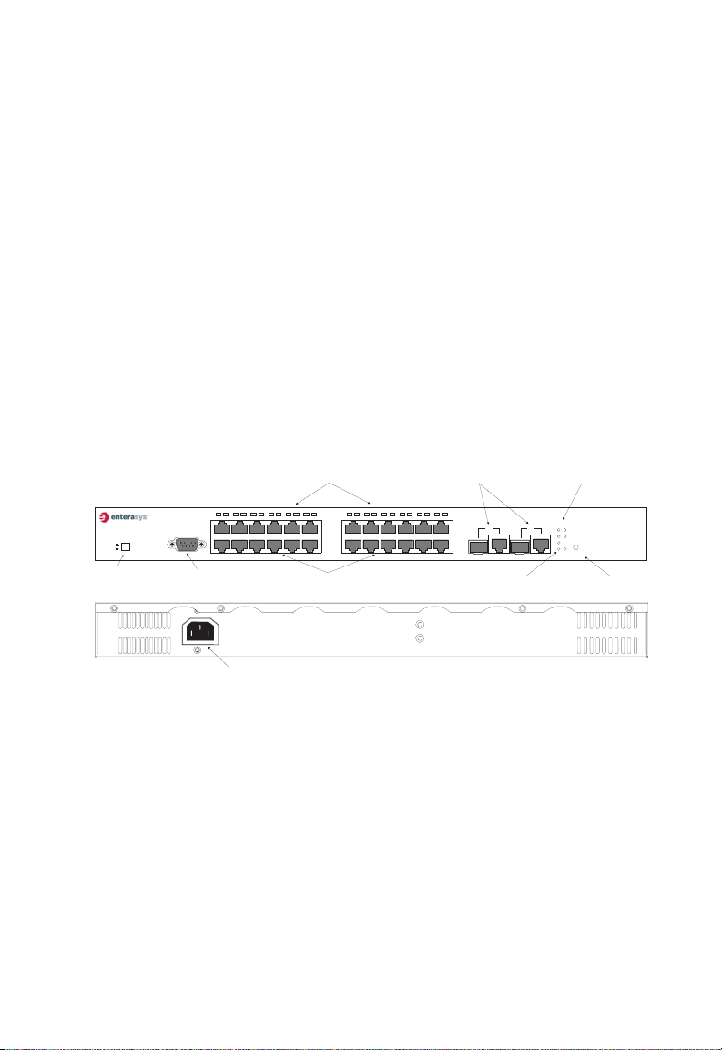
Figure 1-1. Front and Rear Panels 1-1
Figure 1-2. Port LEDs 1-3
Figure 1-3. System LEDs 1-4
Figure 1-4. Stack Master Button 1-6
Figure 1-5. Mode Selection 1-6
Figure 1-6. Optional Stacking Transceiver 1-7
Figure 1-7. Power Supply Receptacle 1-7
Figure 2-1. Collapsed Backbone 2-2
Figure 2-2. Network Aggregation Plan 2-3
Figure 2-3. Remote Connections with Fiber Cable 2-4
Figure 2-4. Making VLAN Connections 2-5
Figure 3-1. RJ-45 Connections 3-2
Figure 3-2. Attaching the Brackets 3-3
Figure 3-3. Installing the Switch in a Rack 3-4
Figure 3-4. Attaching the Adhesive Feet 3-4
Figure 3-5. Installing an SFP Transceiver 3-5
Figure 3-6. Installing a Stacking Transceiver 3-6
Figure 3-7. Connecting Switches in a Stack 3-7
Figure 3-8. Power Receptacle 3-8
Figure 3-9. Serial Port (DB-9 DTE) Pin-Out 3-8
Figure 4-1. Making Twisted-Pair Connections 4-2
Figure 4-2. Network Wiring Connections 4-3
Figure 4-3. Making Fiber Port Connections 4-4
Figure B-1. RJ-45 Connector Pin Numbers B-1
Figure B-2. Straight-through Wiring B-2
Figure B-3. Crossover Wiring B-3
xvii
Page 20

Figures
xviii
Page 21
Chapter 1: Introduction
Overview
The Matrix V-Series V2H124-24P switch contains 24 10BASE-T/100BASE-TX
RJ-45 ports and two combination ports—10/100/1000BASE-T ports that operate in
combination with Small Form Factor Pluggable (SFP) transceiver slots. An optional
SFP stacking transceiver is available for connecting up to eight units to a 1 Gbps
stack backplane.
All the 10BASE-T/100BASE-TX ports on this switch support IEEE 802.3af draft
standard (802.3af) Power-over-Ethernet capabilities. Each port can detect
connected 802.3af-compliant network devices, such as IP phones or wireless
access points, and automatically supply the required DC power.
As well as its Power-over-Ethernet capabilities, the switch provides comprehensive
network management features, such as Spanning Tree Protocol, multicast
switching, virtual LANs, and Layer 2/3/4 CoS services that provide reliability and
consistent performance for your network traffic.
Combination RJ-45/SFP Ports
18 19
20
17
21 222324
Status Indicators (25, 26)
23
25
24
Combination Port
System Indicators
Link/Act
PWR
26
PoE
Diag
25
26
Stacking
PoE/Link
Mode PoE/Link Button
V2H124-24P
Mode
Slave
Master
Stack Master Button
Console
Console Port
100-240V~ 50-60Hz 7.5A
1234567
1
2
Port Status Indicators (1-24)
89
10
131415 16
11 12
11
121314
10/100 Mbps RJ-45 Ports
Power Socket
Figure 1-1. Front and Rear Panels
Switch Architecture
The Matrix V-Series V2H124-24P switch employs a wire-speed, non-blocking
switching fabric. This permits simultaneous wire-speed transport of multiple packets
at low latency on all ports. The switch also features full-duplex capability on all ports,
which effectively doubles the bandwidth of each connection.
The switch uses store-and-forward switching to ensure maximum data integrity. With
store-and-forward switching, the entire packet must be received into a buffer and
checked for validity before being forwarded. This prevents errors from being
propagated throughout the network.
1-1
Page 22

Introduction
1
This switch includes two Gigabit combination ports with RJ-45 connectors and
associated SFP slots. The optional SFP stacking transceiver enables up to eight
units to be connected together through a 1 Gbps stack backplane. The switch stack
can be managed from a master unit using a single IP address.
Power-over-Ethernet Capability
The switch’s 24 10/100 Mbps ports support the IEEE 802.3af Power-over-Ethernet
(PoE) standard that enables DC power to be supplied to attached devices using
wires in the connecting Ethernet cable. Any 802.3af compliant device attached to a
port can directly draw power from the switch over the Ethernet cable without
requiring its own separate power source. This capability gives network
administrators centralized power control for devices such as IP phones and wireless
access points, which translates into greater network availability.
For each attached 802.3af-compliant device, the switch automatically senses the
load and dynamically supplies the required power. The switch delivers power to a
device using the two wire pairs in UTP or STP cable that are not used for 10BASE-T/
100BASE-TX connections. Each port can provide up to 15.4 W of power at the
standard -48 DC voltage. Independent overload and short-circuit protection for each
port allows the switch to automatically shut down a port’s power when limits are
exceeded.
Network devices such as IP phones, wireless access points, and network cameras,
typically consume less than 10 W of power, so they are ideal for
Power-over-Ethernet applications.
Network Management Options
With a comprehensive array of LEDs, this switch provides “at a glance” monitoring of
network and port status. The switch can be managed over the network with a web
browser or Telnet application, or via a direct connection to the console port. The
switch includes a built-in network management agent that allows it to be managed
in-band using SNMP or RMON (Groups 1, 2, 3, 9) protocols. It also has an RS-232
serial port (DB-9 connector) on the front panel for out-of-band management. A PC
may be connected to this port
null-modem serial cable. (See "Connecting to the Console Port" on page 3-8 for
wiring options.)
For a detailed description of the advanced features, refer to the Management Guide.
1-2
for configuration and monitoring out-of-band via a
Page 23

Description of Hardware
1234
56
7
89
1
2
Description of Hardware
10/100BASE-T Ports
The PoE switch base unit contains 24 10BASE-T/100BASE-TX RJ-45 ports. All
ports support automatic MDI/MDI-X operation, so you can use straight-through
cables for all network connections to PCs or servers, or to other switches or hubs.
(See "10/100BASE-TX Pin Assignments" on page B-1.)
Each of these ports support auto-negotiation, so the optimum transmission mode
(half or full duplex), and data rate (10 or 100 Mbps) can be selected automatically. If
a device connected to one of these ports does not support auto-negotiation, the
communication mode of that port can be configured manually.
Each port also supports IEEE 802.3x auto-negotiation of flow control, so the switch
can automatically prevent port buffers from becoming saturated.
1000BASE-T/SFP Ports
These are combination Gigabit RJ-45 ports with alternate Small Form Factor
Pluggable (SFP) transceiver slots. If an SFP transceiver (purchased separately) is
installed in a slot and has a valid link on the port, the associated RJ-45 port is
disabled.
The 1000BASE-T RJ-45 ports support automatic MDI/MDI-X operation, so you can
use straight-through cables for all network connections to PCs or servers, or to other
switches or hubs. (See "1000BASE-T Pin Assignments" on page B-3.)
Note: The 1000BASE-T RJ-45 ports do not support PoE capability.
1
Port and System Status LEDs
The switch base unit also includes a display panel for key system and port
indications that simplify installation and network troubleshooting. The LEDs, which
are located on the front panel for easy viewing, are shown below and described in
the following tables.
Port Status LEDs
Figure 1-2. Port LEDs
1-3
Page 24

Introduction
1
The port status LEDs have two display modes: Link and PoE. The Link mode
displays the link status and network activity on each port. The PoE mode displays
the PoE power status on each port. Use the Mode Link/PoE button (see "Mode PoE/
Link Button" on page 1-6) on the front panel to toggle between the two display
modes. The current mode is indicated by the Link/Act and PoE system LEDs.
Table 1-1. Port Status LEDs
LED Condition Status
1~24
(Link/Act Mode)
On/Flashing Green Port has established a valid 100 Mbps network connection.
On/Flashing Amber Port has established a valid 10 Mbps network connection.
Flashing indicates activity.
Flashing indicates activity.
Alternate Green/Amber Port has been disabled by the administrator.
Off There is no valid link on the port.
1~24
(PoE Mode)
On Green Powered device is connected, but not drawing power.
Flashing Green Powered device is receiving power.
Flashing Amber Port has detected a power overload or short circui t and shut
down the port’s power.
On Amber The power budget for the switch has been exceeded and
the port's power shut down.
Alternate Green/Amber Port has been disabled by the administrator.
Off No powered device is connected to the port.
1-4
System Status LEDs
Link/Act
PWR
PoE
Diag
25
26
Stacking
PoE/Link
Figure 1-3. System LEDs
Mode
Page 25

Description of Hardware
Table 1-2. System Status LEDs
LED Condition Status
PWR On Green Unit’s internal power supply is operating normally.
Off Unit has no power connected.
Diag On Green System diagnostic test successfully completed .
Flashing Green System diagnostic test is in progress.
On Amber System diagnostic test has detected a fault.
Flashing Amber Cannot receive packet from stacking port.
Alternate Green/Amber Fan has failed or the unit has over-heated.
Stacking On Green This switch is acting as the master unit in the stack.
Flashing Green Initial state of stacking configuration to determin whether the
On Amber This switch is acting as a slave unit in the stack.
Link/Act On Green LED display mode is Link/Act.
PoE On Green LED display mode is PoE.
Combination Ports
25-26
(Link/Activity)
On/Flashing Amber Port has established a valid 10/100 Mbps network
On/Flashing Green Port has established a valid 1000 Mbps network connection.
Off There is no valid link on the port.
switch will act as a master or slave unit.
connection. Flashing indicates activity.
Flashing indicates activity.
1
1-5
Page 26

Introduction
1
Stack Master Button
The unit also includes a Stack Master button that is shown in the following diagram.
Stack Master Button
Figure 1-4. Stack Master Button
The Stack Master button enables one switch in the stack to be selected as the
master.
Mode PoE/Link Button
The Mode PoE/Link button is located on the front panel.
Mode Select Button
Link/Act
PWR
PoE
Diag
25
26
Stacking
Mode
PoE/Link
Figure 1-5. Mode Selection
The Mode PoE/Link button is used to toggle between the two port status LED
display modes (see "Port Status LEDs" on page 1-4). Pressing this button changes
from one display mode to the other. The default display mode is Link/Act mode.
1-6
Page 27

Description of Hardware
Optional Stacking Transceiver
TX
RX
Figure 1-6. Optional Stacking Transceiver
The stacking transceiver provides two 1 Gbps ports via USB Type-A connectors.
The upper port is a transmit port and the lower one is a receive port. The transceiver
allows up to eight switches to be linked together using stacking cables. (One
stacking cable is included with each optional stacking transceiver.) The push button
on the switch’s front panel (see "Stack Master Button" on page 1-6) enables one
switch in the stack to be selected as the master.
Power Supply Receptacle
The standard power receptacle is for the AC power cord. It is located on the rear
panel of the switch.
1
100-240V~ 50-60Hz 7.5A
Power Socket
Figure 1-7. Power Supply Receptacle
1-7
Page 28

Introduction
1
Features and Benefits
Connectivity
• 24 dual-speed ports for easy Fast Ethernet integration and for protection of your
investment in legacy LAN equipment
• All 10/100 RJ-45 ports support IEEE 802.3af standard Power-over-Ethernet
• Two Gigabit combination ports—use either 10/100/1000BASE-T RJ-45 port or
Small Form Factor Pluggable (SFP) transceiver slot
• Auto-negotiation enables each RJ-45 port to automatically select the optimum
communication mode (half or full duplex), if this feature is supported for the
attached device
• Independent RJ-45 10/100BASE-TX ports with auto MDI/MDI-X
• Unshielded (UTP) cable supported on all RJ-45 ports: Category 3 or better for
10 Mbps connections, Category 5 or better for 100 Mbps connections, and
Category 5, 5e or 6 for 1000 Mbps connections
• IEEE 802.3u, IEEE 802.3z, and IEEE 802.3ab compliant
Performance
• Transparent bridging
• Aggregate duplex bandwidth of up to 8.8 Gbps
• Switching table with a total of 8K MAC address entries
• Store-and-Forward switching
• Wire-speed filtering and forwarding
• Supports flow control, using back pressure for half duplex and IEEE 802.3x for full
duplex
• Auto MDI/MDIX on all 10/100BASE-TX ports
• Provides Head-of-Line blocking
• Broadcast storm control
• Desktop or rack-mountable
• Stacking capability for up to eight units
Management
• “At-a-glance” LEDs for easy troubleshooting
• Network management agent:
- Manages switch in-band or out-of-band
- Supports Telnet, SNMP/RMON and web-based interface
1-8
Page 29

Chapter 2: Network Planning
Introduction to Switching
A network switch allows simultaneous transmission of multiple packets via
non-crossbar switching. This means that it can partition a network more efficiently
than bridges or routers. The switch has, therefore, been recognized as one of the
most important building blocks for today’s networking technology.
When performance bottlenecks are caused by congestion at the network access
point (such as the network card for a high-volume file server), the device
experiencing congestion (server, power user, or hub) can be attached directly to a
switched port. And, by using full-duplex mode, the bandwidth of the dedicated
segment can be doubled to maximize throughput.
When networks are based on repeater (hub) technology, the maximum distance
between end stations is limited. For Ethernet, there may be up to four hubs between
any pair of stations; for Fast Ethernet, the maximum is two; and for Gigabit Ethernet
the maximum is one. This is known as the hop count. However, a switch turns the
hop count back to zero. So subdividing the network into smaller and more
manageable segments, and linking them to the larger network by means of a switch,
removes this limitation.
A switch can be easily configured in any network to significantly boost bandwidth
while using conventional cabling and network cards.
2-1
Page 30

Network Planning
2
Application Examples
The Matrix V-Series V2H124-24P switch is not only designed to segment your
network, but also to provide a wide range of options in setting up network
connections. Some typical applications are described below.
Collapsed Backbone
The Matrix V-Series V2H124-24P switch is an excellent choice for mixed Ethernet
and Fast Ethernet installations in which significant growth is expected in the near
future. You can easily build on this basic configuration, adding direct full-duplex
connections to workstations or servers. When the time comes for further expansion,
just connect to another hub or switch via one of the switch’s Fast Ethernet or Gigabit
Ethernet ports.
In the figure below, the switch is operating as a collapsed backbone for a small LAN.
It is providing dedicated 10 Mbps full-duplex connections to workstations and
100 Mbps full-duplex connections to power users and servers. In addition,
connected IP phones and wireless access points are receiving PoE power from the
switch.
2-2
...
Servers
100 Mbps
Full Duplex
89
1234567
1
Console
Slave
Master
2
18 19
10
131415 16
20
11 12
17
21 222324
11
121314
...
Workstations
Network Segment
100 Mbps
Full Duplex
Figure 2-1. Collapsed Backbone
100 Mbps
Full Duplex
23
25
24
V2H124-24P
Link/Act
PWR
26
PoE
Diag
25
26
Stacking
Mode
PoE/Link
Power-over-Ethernet Devices
10/100 Mbps
Full Duplex
Standard LAN
PoE
Page 31

Application Examples
Network Aggregation Plan
With 24 parallel bridging ports (i.e., 24 distinct collision domains), the Matrix
V-Series PoE switch can collapse a complex network down into a single efficient
bridged node, increasing overall bandwidth and throughput.
When up to eight switch units are stacked together, they form a single “virtual” switch
containing up to 200 ports. The whole stack can be managed through the Master
unit using a single IP address.
In the figure below, the 10BASE-T/100BASE-TX ports in a switch stack are providing
100 Mbps connectivity for up to 72 segments. In addition, the stack is also
connecting several servers at 1000 Mbps.
2
Switch Units
89
1234567
1
Console
Slave
Master
Slave
Master
Slave
Slave
Master
Master
2
89
1234567
1
Console
2
89
89
1234567
1234567
1
1
Console
Console
2
2
18 19
131415 16
10
10
10
10
20
17
11
121314
11
121314
11
11
121314
121314
131415 16
131415 16
131415 16
21 222324
23
26
25
24
x
T
x
R
18 19
20
21 222324
17
23
26
25
24
242
4
x
T
x
R
18 19
18 19
20
20
17
21 222324
17
21 222324
23
23
26
25
26
25
24
24
242
4
x
T
x
R
11 12
11 12
11 12
11 12
10/100 Mbps Segments
...
...
Figure 2-2. Network Aggregation Plan
V2H124-24P
Link/Act
PWR
PoE
Diag
25
26
Stacking
Mode
PoE/Link
Link/Act
PWR
PoE
Diag
25
26
Stacking
Mode
PoE/Link
Link/Act
Link/Act
PWR
PWR
PoE
Diag
PoE
Diag
25
25
26
26
Stacking
Stacking
Mode
Mode
PoE/Link
PoE/Link
V2H124-24P
V2H124-24P
V2H124-24P
Stacking Cable
Server Farm
2-3
Page 32

Network Planning
2
Remote Connections with Fiber Cable
Fiber optic technology allows for longer cabling than any other media type. Using a
1000BASE-SX multimode fiber (MMF) SFP transceiver, you can run a link up to
550 m. A 1000BASE-LX single-mode fiber (SMF) link can run up to 5 km. A
1000BASE-LH single-mode fiber (SMF) link can run up to 70 km. This allows the
switch to serve as a collapsed backbone, providing direct connectivity for a
widespread LAN.
1000BASE-LX or 1000BASE-LH SFP transceivers can be used to interconnect
remote network segments, or can be used to provide a link to other buildings in a
campus setting. 1000BASE-SX SFP transceivers can be used for Gigabit fiber
connections between floors in the same building.
The figure below illustrates this switch connecting multiple segments with fiber
cable.
Server Farm
Remote Switch
Slave
Master
1234567
1
Console
Slave
Master
1000BASE-LH SMF
(70 kilometers)
2
89
10
11 12
11
121314
131415 16
18 19
20
21 222324
17
23
24
Remote Switch
Console
1211
1112
1213142324
V2H124-24P
Link/Act
PWR
26
25
PoE
Diag
25
26
Stacking
Mode
PoE/Link
Slave
Master
1211
Console
18 19
89
20
13141516
10
21222324
17
1112
1234567
1213142324
25
18 19
89
13141516
20
10
17
21222324
1234567
10/100 Mbps Segments
...
...
Figure 2-3. Remote Connections with Fiber Cable
Link/Act
PWR
26
25
Diag
PoE
25
26
Stacking
1000BASE-LX SMF
(5 kilometers)
V2H124-24P
Link/Act
PWR
26
Diag
PoE
25
26
Stacking
Mode
PoE/Link
V2H124-24P
Mode
PoE/Link
2-4
Page 33

Application Examples
Making VLAN Connections
This switch supports VLANs which can be used to organize any group of network
nodes into separate broadcast domains. VLANs confine broadcast traffic to the
originating group, and can eliminate broadcast storms in large networks. This
provides a more secure and cleaner network environment.
VLANs can be based on untagged port groups, or traffic can be explicitly tagged to
identify the VLAN group to which it belongs. Unttagged VLANs can be used for small
networks attached to a single switch. However, tagged VLANs should be used for
larger networks, and all the VLANs assigned to the inter-switch links.
The switch also supports multiple spanning trees which allow VLAN groups to
maintain a more stable path between all VLAN members. This can reduce the
overall amount of protocol traffic crossing the network, and provide a shorter
reconfiguration time when any link in the spanning tree fails.
2
R&D
Testing
VLAN 2
VLAN 1
Tagged
Ports
Finance
VLAN 3
Slave
Master
VLAN 4
Console
Untagged Ports
Marketing
1234567
1
2
VLAN
unaware
switch
89
10
11 12
11
121314
131415 16
18 19
20
17
21 222324
23
24
26
25
V2H124-24P
Link/Act
PWR
Diag
PoE
25
26
Stacking
Mode
PoE/Link
Tagged Port
VLAN
aware
switch
VLAN 1
R&D
Testing
VLAN 2
Finance
VLAN 3
Figure 2-4. Making VLAN Connections
Note: When connecting to a switch that does not support IEEE 802.1Q VLAN tags, use
untagged ports.
2-5
Page 34

Network Planning
2
Application Notes
1. Full-duplex operation only applies to point-to-point access (such as when a
switch is attached to a workstation, server or another switch). When the switch
is connected to a hub, both devices must operate in half-duplex mode.
2. Avoid using flow control on a port connected to a hub unless it is actually
required to solve a problem. Otherwise back pressure jamming signals may
degrade overall performance for the segment attached to the hub.
3. As a general rule the length of fiber optic cable for a single switched link should
not exceed:
• 1000BASE-SX: 550 m (1805 ft) using multimode fiber
• 1000BASE-LX: 5 km (3.2 miles) using single-mode fiber
• 100BASE-LH: 70 km (43.5 miles) using single-mode fiber
However, power budget constraints must also be considered when calculating
the maximum cable length for your specific environment.
2-6
Page 35

Chapter 3: Installing the Switch
Selecting a Site
Matrix V-Series V2H124-24P units can be mounted in a standard 19-inch equipment
rack or on a flat surface. Be sure to follow the guidelines below when choosing a
location.
• The site should:
- be at the center of all the devices you want to link and near a power outlet.
- be able to maintain its temperature within 0 to 50 °C (32 to 122 °F), and its
humidity within 5% to 95%, non-condensing
- provide adequate space (approximately two inches) on all sides for proper air
flow
- be accessible for installing, cabling, and maintaining the devices
- allow the status LEDs to be clearly visible
• Make sure that twisted-pair cable is always routed away from power lines,
fluorescent lighting fixtures and other sources of electrical interference, such as
radios and transmitters.
• Make sure that the unit is connected to a separate grounded power outlet that:
- provides 100 to 240 VAC, 50 to 60 Hz
- is within 2.44 m (8 feet) of each device
- is powered from an independent circuit breaker
• As with any equipment, using a filter or surge suppressor is recommended.
Ethernet Cabling
To ensure proper operation when installing the switch into a network, make sure that
the current cables are suitable for 10BASE-T or 100BASE-TX operation. Check the
following criteria against the current installation of your network:
• Cable type: Unshielded twisted pair (UTP) or shielded twisted pair (STP) cables
with RJ-45 connectors; Category 3 or better for 10BASE-T and Category 5 or
better for 100BASE-TX.
• Protection from radio frequency interference emissions
• Electrical surge suppression
• Separation of electrical wires (switch related or other) and electromagnetic fields
from data based network wiring
• Safe connections with no damaged cables, connectors or shields
3-1
Page 36

Installing the Switch
3
RJ-45 Connector
Figure 3-1. RJ-45 Connections
Equipment Checklist
After unpacking this switch, check the contents to be that sure you have received all
the components. Then, before beginning the installation, be sure that you have all
other necessary installation equipment.
Package Contents
• 24-Port Fast Ethernet V2H124-24P Switch
• AC power cord
• Owner registration card
• Serial cable
• Rack mounting kit
• Quick Reference Guide
Getting Help
For additional support related to the product or this document, contact Enterasys
Networks using one of the following methods:
Web http://www.enterasys.com/support
Phone 603-332-9400
1-800-872-8440 (toll-free in U.S. and Canada)
For the Enterasys Networks Support toll-free number in your country:
http://www.entrerasys.com/support/gtac-all.html
Internet mail support@enterasys.com
To expedite your message, please type [eth] in the subject line.
•
3-2
Page 37

Mounting
Optional Rack-Mounting Equipment
If you plan to rack-mount the switch, be sure to have the following equipment
available:
• Four mounting screws for each device you plan to install in a rack—these are not
included
• A screwdriver (Phillips or flathead, depending on the type of screws used)
Mounting
This switch can be mounted in a standard 19-inch equipment rack or on a desktop or
shelf. Mounting instructions for each type of site follow.
Rack Mounting
Before rack mounting the switch, pay particular attention to the following factors:
• Temperature: Since the temperature within a rack assembly may be higher than
the ambient room temperature, check that the rack-environment temperature is
within the specified operating temperature range. (See page C-1.)
• Mechanical Loading: Do not place any equipment on top of a rack-mounted unit.
• Circuit Overloading: Be sure that the supply circuit to the rack assembly is not
overloaded.
• Grounding: Rack-mounted equipment should be properly grounded. Particular
attention should be given to supply connections other than direct connections to
the mains.
To rack-mount devices:
1. Attach the brackets to the device using the screws provided in the Bracket
Mounting Kit.
3
2
5
2
6
L
in
k
/A
c
t
P
W
R
P
o
E
D
ia
g
2
5
2
6
Sta
c
k
V2H124-24P
in
g
M
o
d
e
P
o
E
/L
in
k
Figure 3-2. Attaching the Brackets
3-3
Page 38

Installing the Switch
3
2. Mount the device in the rack, using four rack-mounting screws (not provided).
2
5
2
6
Lin
k/Act
P
W
R
P
o
E
D
ia
2
5
26
Stackin
V2H124-24P
g
g
M
o
d
e
PoE
/Lin
k
Figure 3-3. Installing the Switch in a Rack
3. If installing a single switch only, turn to “Connecting to a Power Source” at the
end of this chapter.
4. If installing multiple switches, mount them in the rack, one below the other, in
any order.
Desktop or Shelf Mounting
1. Attach the four adhesive feet to the bottom of the first switch.
k
in
L
/
E
o
P
e
d
o
M
g
in
k
c
Sta
6
2
5
2
g
ia
D
E
o
P
V2H124-24P
R
W
P
t
c
/A
k
in
3-4
L
6
2
4
2
5
2
3
2
4
2
3
2
2
2
1
2
4
1
2
0
2
9
1
81
1
7
1
6
1
5
1
3
1
4
1
3
1
11
2
1
11
0
1
9
2
8
7
e
l
o
6
s
n
o
C
5
4
3
1
2
1
Figure 3-4. Attaching the Adhesive Feet
r
e
t
s
a
M
e
v
a
l
S
Page 39

Installing an SFP Transceiver
122
2. Set the device on a flat surface near an AC power source, making sure there
are at least two inches of space on all sides for proper air flow.
3. If installing a single switch only, go to “Connecting to a Power Source” at the
end of this chapter.
4. If installing multiple switches, attach four adhesive feet to each one. Place each
device squarely on top of the one below, in any order.
Installing an SFP Transceiver
23
24
23
Link/A
ct
P
W
R
P
oE
24
Figure 3-5. Installing an SFP Transceiver
D
ia
g
25
26
Stacking
M
ode
P
oE
/Link
V2H124-24P
3
To install an SFP transceiver, perform the following steps:
1. Consider your network and cabling requirements to select an appropriate SFP
transceiver type.
2. Insert the transceiver with the optical connector facing outward and the slot
connector facing down. Note that SFP transceivers are keyed so they can only
be installed in one orientation.
3. Slide the SFP transceiver into the slot until it clicks into place.
Note: SFP transceivers are hot-swappable. The switch does not need to be powered off
before installing or removing a transceiver. However, always first disconnect the
network cable before removing a transceiver.
3-5
Page 40

Installing the Switch
2
2
2
2
3
Stacking Switches
The switch supports stacking up to eight units through an optional SFP stacking
transceiver. The stacking transceiver must be installed in the port 25 slot. Each
stacking transceiver has two connectors, Tx and Rx, for attaching stacking cables.
Figure 3-7 shows how stacking cables are connected between switches in a stack.
Note: The stacking transceiver must only be installed in the port 25 SFP slot.
Installing a Stacking Transceiver
The stacking transceiver must be installed in the port 25 slot. It should be inserted
before any of the systems in the stack are powered on.
3
3
24
24
23
23
25
25
Tx
Rx
Remove Transceiver
by Pulling Tab
Figure 3-6. Installing a Stacking Transceiver
Slide Transceiver into
SFP Transceiver Slot
Slide the SFP transceiver into the SFP transceiver slot until it clicks into place. To
remove, pull on the tab at the bottom of the front of the transceiver.
3-6
Page 41

Stacking Switches
Connecting Switches in a Stack
1
1
3
3
1
1
4
4
1
1
3
3
1
1
5
5
1
1
6
6
1
1
7
7
1
1
8
8
1
1
9
9
2
2
0
0
2
2
1
1
2
2
2
2
2
2
3
3
2
2
4
4
2
2
3
1
1
4
4
1
1
3
3
1
1
4
4
1
1
3
3
1
1
5
5
1
1
1
1
4
4
1
1
3
3
1
1
4
4
1
1
3
3
1
1
5
5
1
1
1
1
4
4
3
2
2
5
5
2
2
6
2
2
4
4
6
6
1
1
7
7
1
1
8
8
1
1
9
9
2
2
0
0
2
2
1
1
2
2
2
2
2
2
3
3
2
2
4
4
2
2
3
3
6
6
1
1
7
7
1
1
8
8
1
1
9
9
2
2
0
0
2
2
1
1
2
2
2
2
2
2
3
3
2
2
4
4
2
2
3
3
2
2
4
4
6
L
L
i
i
n
n
k
k
/
/
A
A
c
c
t
t
P
P
W
W
R
R
V2H124-24P
P
P
o
o
E
E
D
D
i
i
a
Tx
x
R
2
2
5
5
Tx
x
R
2
2
5
5
Tx
x
R
a
g
g
2
2
5
5
2
2
6
6
Sta
Sta
c
c
k
k
in
in
g
g
M
M
o
o
d
d
e
e
P
P
o
o
E
E
/
/
L
L
i
i
n
n
k
k
2
2
6
6
L
L
i
i
n
n
k
k
/
/
A
A
c
c
t
t
P
P
V2H124-24P
W
W
R
R
P
P
o
o
E
E
D
D
ia
ia
g
g
2
2
5
5
2
2
6
6
Sta
Sta
c
c
k
k
i
i
n
n
g
g
M
M
o
o
d
d
e
e
P
P
o
o
E
E
/L
/L
i
i
n
n
k
k
2
2
6
6
L
L
in
in
k
k
/
/
A
A
c
c
t
t
P
P
W
W
V2H124-24P
R
R
P
P
o
o
E
E
D
D
ia
ia
g
g
2
2
5
5
2
2
6
6
Sta
Sta
c
c
k
k
i
i
n
n
g
g
M
M
o
o
d
d
e
e
P
P
o
o
E
E
/L
/L
i
i
n
n
k
k
Figure 3-7. Connecting Switches in a Stack
Note: The stacking transceiver must only be installed in the port 25 SFP slot.
To connect up to eight switches in a stack, perform the following steps:
1. Install SFP stacking transceivers into the port 25 slot for each switch in the
stack.
Stack Master
Slave
Slave
3
2. Plug one end of a stack cable into the Tx (top) port of the top unit
3. Plug the other end of the stack cable into the Rx (bottom) port of the next unit.
4. Repeat steps 1 and 2 for each unit in the stack. Form a simple chain starting at
the Tx port on the top unit and ending at the Rx port on the bottom unit
(stacking up to 8 units).
5. Complete the stack connections by plugging one end of a stack cable into the
Tx port on the bottom unit and the other end into the Rx port on the top unit.
6. Select the Master unit in the stack by pressing the push button in on only one of
the switches. Only one switch in the stack can operate as the Master, all other
units operate in slave mode. If more than one switch in the stack is selected as
Master, or if no switches are selected, the stack will not function.
Note: The stacking feature requires that all stacking transceiver ports be connected and
the switches powered on. If one stack link is not connected, the switches will
operate as independent switches. If one of the switches in a stack is not powered
on or fails, the remaining switches will operate as independent switches.
3-7
Page 42

Installing the Switch
3
Connecting to a Power Source
To connect a switch to a power source:
1. Insert the power cable plug directly into the AC receptacle located at the back
of the switch.
100-240V~ 50-60Hz 7.5A
Power Socket
Figure 3-8. Power Receptacle
2. Plug the other end of the cable into a grounded, 3-pin socket, AC power source.
Note: For international use, you may need to change the AC line cord. You must use a
line cord set that has been approved for the receptacle type in your country.
3. Check the front-panel LEDs as the device is powered on to be sure the PWR
LED is lit. If not, check that the power cable is correctly plugged in.
Connecting to the Console Port
The DB-9 serial port on the switch’s front panel is used to connect to the switch for
out-of-band console configuration. The command-line configuration program can be
accessed from a terminal or a PC running a terminal emulation program. The pin
assignments used to connect to the serial port are provided in the following table.
1
Figure 3-9. Serial Port (DB-9 DTE) Pin-Out
3-8
5
6 9
Page 43

Wiring Map for Serial Cable
Table 3-1. Serial Cable Wiring
Connecting to the Console Port
3
Switch’s 9-Pin
Serial Port
2 RXD (receive data) <---------------------------- 3 TXD (transmit data)
3 TXD (transmit data) -----------------------------> 2 RXD (receive data)
5 SGND (signal ground) ------------------------------ 5 SGND (signal ground)
No other pins are used.
The serial port’s configuration requirements are as follows:
• Default Baud rate—9,600 bps
• Character Size—8 Characters
• Parity—None
• Stop bit—One
• Data bits—8
Null Modem PC’s 9-Pin
DTE Port
3-9
Page 44

Installing the Switch
3
3-10
Page 45

Chapter 4: Making Network Connections
Connecting Network Devices
The Matix V-Series V2H124-24P switch is designed to be connected to 10 or
100 Mbps network cards in PCs and servers, as well as to other switches and hubs.
It may also be connected to remote devices using the optional 1000BASE-SFP
transceivers.
If 802.3af-compliant PoE devices are connected to the switch’s 10/100 Mbps ports,
the switch automatically supplies the required power.
Twisted-Pair Devices
Each device requires an unshielded twisted-pair (UTP) cable with RJ-45 connectors
at both ends. Use Category 5, 5e or 6 cable for 1000BASE-T connections, Category
5 or better for 100BASE-TX connections, and Category 3 or better for 10BASE-T
connections.
Power-over-Ethernet Connections
The Matrix V-Series V2H124-24P switch automatically detects an 802.3af-compliant
device by its authenticated PoE signature and senses its required load before
turning on DC power to the port. This detection mechanism prevents damage to
other network equipment that is not 802.3af complaint.
Note: Power-over-Ethernet connections work with all existing Category 3, 4, 5, 5e or 6
network cabling, including patch cables and patch-panels, outlets, and other
connecting hardware, without requiring modification.
The switch delivers power to a device using the two unused wire pairs in UTP or
STP cable (RJ-45 pins 4, 5, 7, and 8). The switch can provide up to 15.4 W of power
continuously on each 10/100 Mbps port. However, taking into account some power
loss over the cable run, the amount of power that can be delivered to a terminal
device is 12.95 W. If a device draws more than 15.4 W, from a port, an overload
condition occurs and the port turns off the power.
The switch controls the power and data on a port independently. Power can be
requested from a device that already has a data link to the switch. Also, the switch
can supply power to a device even if the port’s data connection has been disabled.
The power on a port is continuously monitored by the switch and it will be turned off
as soon as a device connection is removed.
4-1
Page 46

Making Network Connections
4
Cabling Guidelines
The RJ-45 ports on the switch support automatic MDI/MDI-X pinout configuration, so
you can use standard straight-through twisted-pair cables to connect to any other
network device (PCs, servers, switches, routers, or hubs).
See Appendix B for further information on cabling.
Caution: Do not plug a normal phone jack connector into an RJ-45 port. This will
damage the switch. Use only twisted-pair cables with RJ-45 connectors that
conform to FCC standards.
Connecting to PCs, Servers, Hubs and Switches
1. Attach one end of a twisted-pair cable segment to the device’s RJ-45
connector.
Figure 4-1. Making Twisted-Pair Connections
2. If the device is a network card and the switch is in the wiring closet, attach the
other end of the cable segment to a modular wall outlet that is connected to the
wiring closet. (See the section “Network Wiring Connections.”) Otherwise,
attach the other end to an available port on the switch.
Make sure each twisted pair cable does not exceed 100 meters (328 ft) in
length.
Note: Avoid using flow control on a port connected to a hub unless it is actually required
to solve a problem. Otherwise back pressure jamming signals may degrade
overall performance for the segment attached to the hub.
3. As each connection is made, the green Link LED (on the switch) corresponding
to each port will light to indicate that the connection is valid.
4-2
Page 47

Twisted-Pair Devices
Network Wiring Connections
Today, the punch-down block is an integral part of many newer equipment racks. It is
actually part of the patch panel. Instructions for making connections in the wiring
closet with this type of equipment follow.
1. Attach one end of a patch cable to an available port on the switch, and the other
end to the patch panel.
2. If not already in place, attach one end of a cable segment to the back of the
patch panel where the punch-down block is located, and the other end to a
modular wall outlet.
3. Label the cables to simplify future troubleshooting.
Switch
18 19
89
20
10
13141516
21222324
111 2
17
1234567
1211
Console
Slave
Master
1213142324
V2H124-24P
Link/Act
PWR
26
25
PoE
Diag
25
26
Stacking
Mode
PoE/Link
Equipment Rack
(side view)
Punch-Down Block
4
Patch Panel
Wall
Figure 4-2. Network Wiring Connections
4-3
Page 48

Making Network Connections
4
Fiber Optic Devices
An optional slide-in 1000BASE-SX, 1000BASE-LX, or 1000BASE-LH SFP
transceiver may be used for backbone or remote connections, or for connecting to a
high-speed server.
Each single-mode fiber optic port requires 9/125 micron single-mode fiber optic
cabling with an LC connector at both ends. Each multimode fiber optic port requires
50/125 or 62.5/125 micron multimode fiber optic cabling with an LC connector at
both ends.
Warning: This switch uses lasers to transmit signals over fiber optic cable. The lasers are
compliant with the requirements of a Class 1 Laser Product and are inherently
eye safe in normal operation. However, you should never look directly at a
transmit port when it is powered on.
1. Remove and keep any protective port covers. When not connected to a fiber
cable, the cover should be replaced to protect the optics.
2. Check that the fiber terminators are clean. You can clean the cable plugs by
wiping them gently with a clean tissue or cotton ball moistened with a little
ethanol. Dirty fiber terminators on fiber optic cables will impair the quality of the
light transmitted through the cable and lead to degraded performance on the
port.
3. Connect one end of the cable to the LC port on the switch and the other end to
the port on the other device. Since LC connectors are keyed, the cable can be
attached in only one orientation.
Figure 4-3. Making Fiber Port Connections
4. As a connection is made, check the green Link LED on the switch
corresponding to the port to be sure that the connection is valid.
4-4
Page 49

Connectivity Rules
Connectivity Rules
When adding hubs (repeaters) to your network, please follow the connectivity rules
listed in the manuals for these products. However, note that because switches break
up the path for connected devices into separate collision domains, you should not
include the switch or connected cabling in your calculations for cascade length
involving other devices.
1000BASE-T Cable Requirements
All Category 5 UTP cables that are used for 100BASE-TX connections should also
work for 1000BASE-T, providing that all four wire pairs are connected. However, it is
recommended that for all critical connections, or any new cable installations,
Category 5e (enhanced Category 5) or Category 6 cable should be used. The
Category 5e and 6 specifications include test parameters that are only
recommendations for Category 5. Therefore, the first step in preparing existing
Category 5 cabling for running 1000BASE-T is a simple test of the cable installation
to be sure that it complies with the IEEE 802.3ab standards.
1000 Mbps Gigabit Ethernet Collision Domain
Table 4-1. Maximum 1000BASE-T Gigabit Ethernet Cable Length
Cable Type Maximum Cable Length Connector
Category 5, 5e, or 6 100-ohm UTP or STP 100 m (328 ft) RJ-45
4
Table 4-2. Maximum 1000BASE-SX Gigabit Ethernet Cable Lengths
Fiber Size Fiber Bandwidth Maximum Cable Length Connector
62.5/125 micron
multimode fiber
50/125 micron multimode
fiber
Table 4-3. Maximum 1000BASE-LX Gigabit Ethernet Cable Length
Fiber Size Fiber Bandwidth Maximum Cable Length Connector
9/125 micron
single-mode fiber
160 MHz/km 2-220 m (7-722 ft) LC
200 MHz/km 2-275 m (7-902 ft) LC
400 MHz/km 2-500 m (7-1641 ft) LC
500 MHz/km 2-550 m (7-1805 ft) LC
N/A 2 m - 5 km (7 ft - 3.2 miles) LC
4-5
Page 50

Making Network Connections
4
Table 4-4. Maximum 1000BASE-LH Gigabit Ethernet Cable Length
Fiber Size Fiber Bandwidth Maximum Cable Length Connector
9/125 micron
single-mode fiber
N/ A 2 m - 7 0 k m ( 7 ft - 4 3.5 mi les ) LC
100 Mbps Fast Ethernet Collision Domain
Table 4-5. Maximum Fast Ethernet Cable Lengths
Type Cable Type Max. Cable Length Connector
100BASE-TX Category 5 or better 100-ohm UTP or STP 100 m (328 ft) RJ-45
10 Mbps Ethernet Collision Domain
Table 4-6. Maximum Ethernet Cable Length
Cable Type Maximum Length Connector
Twisted Pair, Category 3 or better 100-ohm UTP 100 m (328 ft) RJ-45
Cable Labeling and Connection Records
When planning a network installation, it is essential to label the opposing ends of
cables and to record where each cable is connected. Doing so will enable you to
easily locate inter-connected devices, isolate faults and change your topology
without need for unnecessary time consumption.
To best manage the physical implementations of your network, follow these
guidelines:
• Clearly label the opposing ends of each cable.
• Using your building’s floor plans, draw a map of the location of all
network-connected equipment. For each piece of equipment, identify the devices
to which it is connected.
• Note the length of each cable and the maximum cable length supported by the
switch ports.
• For ease of understanding, use a location-based key when assigning prefixes to
your cable labeling.
• Use sequential numbers for cables that originate from the same equipment.
• Differentiate between racks by naming accordingly.
• Label each separate piece of equipment.
• Display a copy of your equipment map, including keys to all abbreviations at each
equipment rack.
4-6
Page 51

Appendix A: Troubleshooting
Diagnosing Switch Indicators
Table A-1. Troubleshooting Chart
Symptom Action
PWR LED is Off • Internal power supply may be disconnected. Check connections
Diag LED is Amber • The system has detected a fault. Power cycle the switch to try and
Diag LED is Flashing Amber • Check that all stacking cables are properly connected.
Stack LED is Flashing Green or
Amber
Link/Act LED is Off • Verify that the switch and attached device are powered on.
between the switch, the power cord and the wall outlet.
clear the condition.
• If the condition does not clear, contact your dealer for assistance.
• The stack has not completed its initial configuration. Wait a few
minutes for the process to complete.
• If flashing continues, check that the Master Select button is pressed in
on only one switch.
• Check that all stacking cables are properly connected.
• Be sure the cable is plugged into both the switch and corresponding
device.
• If the switch is installed in a rack, check the connections to the
punch-down block and patch panel.
• Verify that the proper cable type is used and its length does not exceed
specified limits.
• Check the adapter on the attached device and cable connections for
possible defects. Replace the defective adapter or cable if necessary.
Note: For additional troubleshooting information, go to the Enterasys Global
Knowledgebase web site: http://knowledgebase.enterasys.com/esupport/
Power and Cooling Problems
If the power indicator does not turn on when the power cord is plugged in, you may
have a problem with the power outlet, power cord, or internal power supply.
However, if the unit powers off after running for a while, check for loose power
connections, power losses or surges at the power outlet, and verify that the fans on
the unit are unobstructed and running prior to shutdown. If you still cannot isolate the
problem, the internal power supply may be defective.
A-1
Page 52

A
Troubleshooting
Installation
Verify that all system components have been properly installed. If one or more
components appear to be malfunctioning (such as the power cord or network
cabling), test them in an alternate environment where you are sure that all the other
components are functioning properly.
In-Band Access
You can access the management agent in the switch from anywhere within the
attached network using Telnet, a web browser, or other network management
software tools. However, you must first configure the switch with a valid IP address,
subnet mask, and default gateway. If you have trouble establishing a link to the
management agent, check to see if you have a valid network connection. Then
verify that you entered the correct IP address. Also, be sure the port through which
you are connecting to the switch has not been disabled. If it has not been disabled,
then check the network cabling that runs between your remote location and the
switch.
Note: The management agent accepts up to four simultaneous Telnet sessions. If the
maximum number of sessions already exists, an additional Telnet connection
will not be able to log into the system.
Stack Troubleshooting
If a stack fails to initialize or function, first check the following items:
• Check that all stacking cables are properly connected.
• Check if any stacking cables appear damaged.
• Check that no more than one Master Select button is pressed in.
• Check that all switches in the stack are powered on.
After checking all items, reboot all the switches in the stack. If the problem is still not
resolved, contact your dealer for assistance.
A-2
Page 53

Appendix B: Cables
Twisted-Pair Cable and Pin Assignments
Caution: DO NOT plug a normal phone jack connector into any RJ-45 port. Use only
For 10/100BASE-TX connections, the twisted-pair cable must have two pairs of
wires. For 1000BASE-T connections the twisted-pair cable must have four pairs of
wires. Each wire pair is identified by two different colors. For example, one wire
might be green and the other, green with white stripes. Also, an RJ-45 connector
must be attached to both ends of the cable.
Caution: Each wire pair must be attached to the RJ-45 connectors in a specific
Figure B-1 illustrates how the pins on the RJ-45 connector are numbered. Be sure to
hold the connectors in the same orientation when attaching the wires to the pins.
twisted-pair cables with RJ-45 connectors that conform with FCC standards.
orientation. (See “Cabling Guidelines” on page 4-2 for an explanation.)
8
1
Figure B-1. RJ-45 Connector Pin Numbers
8
1
10/100BASE-TX Pin Assignments
Use unshielded twisted-pair (UTP) or shielded twisted-pair (STP) cable for RJ-45
connections: 100-ohm Category 3 or better cable for 10 Mbps connections, or
100-ohm Category 5 or better cable for 100 Mbps connections. Also be sure
length of any twisted-pair connection does not exceed 100 meters (328 feet).
Data is delivered on the standard two wire pairs (pins 1, 2, 3, and 6), and PoE power
is supplied using the two previously spare pairs (pins 4, 5, 7, and 8). Since the RJ-45
ports on the switch base unit support automatic MDI/MDI-X operation, you can use
straight-through cables for all network connections to PCs or servers, or to other
switches or hubs. In straight-through cable, pins 1, 2, 3, and 6, at one end of the
cable, are connected straight through to pins 1, 2, 3, and 6 at the other end of the
cable. When using any RJ-45 port on this switch, you can use either straight-through
or crossover cable.
that the
B-1
Page 54

B
Cables
Table B-1. 10/100BASE-TX MDI and MDI-X Port Pinouts
Pin MDI-X Signal Name MDI Signal Name
1 Receive Data plus (RD+) Transmit Data plus (TD+)
2 Receive Data minus (RD-) Transmit Data minus (TD-)
3
4
5
6
7
8
Transmit Data plus (TD+) Receive Data plus (RD+)
GND (Positive V
GND (Positive V
) GND (Positive V
port
) GND (Positive V
port
port
port
)
)
Transmit Data minus (TD-) Receive Data minus (RD-)
-48V feeding power (Negative V
-48V feeding power (Negative V
) -48V feeding power (Negative V
port
) -48V feeding power (Negative V
port
port
port
)
)
Note: The “+” and “-” signs represent the polarity of the wires that make up each wire pair.
Straight-Through Wiring
If the twisted-pair cable is to join two ports and only one of the ports has an internal
crossover (MDI-X), the two pairs of wires must be straight-through. (When
auto-negotiation is enabled for any RJ-45 port on this switch, you can use either
straight-through or crossover cable to connect to any device type.)
EIA/TIA 568B RJ-45 WiringStandard
10/100BASE-TX Straight-through Cable
White/Orange Stripe
Orange
End A
1
2
3
4
5
6
7
8
White/Green Stripe
Blue
White/Blue Stripe
Green
White/Brown Stripe
1
2
3
4
5
6
7
8
End B
Brown Stripe
Figure B-2. Straight-through Wiring
Crossover Wiring
If the twisted-pair cable is to join two ports and either both ports are labeled with an
“X” (MDI-X) or neither port is labeled with an “X” (MDI), a crossover must be
implemented in the wiring. (When auto-negotiation is enabled for any RJ-45 port on
this switch, you can use either straight-through or crossover cable to connect to any
device type.)
B-2
Page 55

Twisted-Pair Cable and Pin Assignments
White/Orange Stripe
Orange
End A
1
2
3
4
5
6
7
8
White/Green Stripe
Blue
White/Blue Stripe
Green
White/Brown Stripe
Brown Stripe
1
2
3
4
5
6
7
8
End B
Figure B-3. Crossover Wiring
1000BASE-T Pin Assignments
All 1000BASE-T ports support automatic MDI/MDI-X operation, so you can use
straight-through cables for all network connections to PCs or servers, or to other
switches or hubs.
The table below shows the 1000BASE-T MDI and MDI-X port pinouts. These ports
require that all four pairs of wires be connected. Note that for 1000BASE-T
operation, all four pairs of wires are used for both transmit and receive.
Use 100-ohm Category 5, 5e or 6 unshielded twisted-pair (UTP) or shielded
twisted-pair (STP) cable for 1000BASE-T connections. Also be sure
of any twisted-pair connection does not exceed 100 meters (328 feet)
that the length
.
B
Table B-2. 1000BASE-T MDI and MDI-X Port Pinouts
1000BASE-T MDI and MDI-X Port Pinouts
Pin MDI-X Signal Name MDI Signal Name
1 Bi-directional Data Two Plus (BI_D2+) Bi-directional Data One Plus (BI_D1+)
2 Bi-directional Data Two Minus (BI_D2-) Bi-directional Data One Minus (BI_D1-)
3 Bi-directional Data One Plus (BI_D1+) Bi-directional Data Two Plus (BI_D2+)
4 Bi-directional Data Four Plus (BI_D4+) Bi-directional Data Three Plus (BI_D3+)
5 Bi-directional Data Four Minus (BI_D4-) Bi-directional Data Three Minus (BI_D3-)
6 Bi-directional Data One Minus (BI_D1-) Bi-directional Data Two Minus (BI_D2-)
7 Bi-directional Data One Plus (BI_D3+) Bi-directional Data One Plus (BI_D4+)
8 Bi-directional Data Three Minus (BI_D3-) Bi-directional Data Four Minus (BI_D4-)
B-3
Page 56

B
Cables
Cable Testing for Existing Category 5 Cable
Installed Category 5 cabling must pass tests for Attenuation, Near-End Crosstalk
(NEXT), and Far-End Crosstalk (FEXT). This cable testing information is specified in
the ANSI/TIA/EIA-TSB-67 standard. Cables must also pass test parameters for
Return Loss and Equal-Level Far-End Crosstalk (ELFEXT). These tests are
specified in the ANSI/TIA/EIA-TSB-95 Bulletin, “The Additional Transmission
Performance Guidelines for 100 Ohm 4-Pair Category 5 Cabling.”
Note that when testing your cable installation, be sure to include all patch cables
between switches and end devices.
Adjusting Existing Category 5 Cabling to Run 1000BASE-T
If your existing Category 5 installation does not meet one of the test parameters for
1000BASE-T, there are basically three measures that can be applied to try to correct
the problem:
1. Replace any Category 5 patch cables with high-performance Category 5e or
Category 6 cables.
2. Reduce the number of connectors used in the link.
3. Reconnect some of the connectors in the link.
Fiber Standards
The current TIA (Telecommunications Industry Association) 568-A specification on
optical fiber cabling consists of one recognized cable type for horizontal subsystems
and two cable types for backbone subsystems.
Horizontal 62.5/125 micron multimode (two fibers per outlet).
Backbone 62.5/125 micron multimode or single-mode.
TIA 568-B will allow the use of 50/125 micron multimode optical fiber in both the
horizontal and backbone in addition to the types listed above. All optical fiber
components and installation practices must meet applicable building and safety
codes.
B-4
Page 57

Appendix C: Specifications
Physical Characteristics
Ports
24 10/100BASE-TX, with auto-negotiation
2 1000BASE-T/SFP combination ports
Network Interface
Ports 1-24: RJ-45 connector, auto MDI/X
10BASE-T: RJ-45 (100-ohm, UTP cable; Categories 3 or better)
100BASE-TX: RJ-45 (100-ohm, UTP cable; Category 5 or better)
Ports 25, 26: RJ-45 connector, auto MDI/X
1000BASE-T: RJ-45 (100-ohm, UTP cable; Category 5, 5e, or 6)
Buffer Architecture
8 Mbytes
Aggregate Bandwidth
8.8 Gbps
Switching Database
8K MAC address entries
LEDs
System: PWR, Diag, Stacking
Link/Act, PoE
Ports:
Weight
5.76 kg (12 lbs 11 oz)
Size
44.0 x 41.0 x 4.3 cm (17.32 x 16.14 x 1.69 in.)
Temperature
Operating: 0 °C to 50 °C (32 °F to 122 °F)
Storage: -40 °C to 70 °C (-40 °F to 158 °F)
C-1
Page 58

C
Specifications
Power-over-Ethernet
Input voltage: - 48 V DC
Maximum output power per port: 15.4 W
Output Voltage: 44 - 57 V DC
Maximum output current per port: 350 mA DC
Power Supply
Internal, auto-ranging transformer: 100 to 240 VAC, 47 to 63 Hz
Power Consumption
48 Watts (Switching system)
370 Watts (Power-over-Ethernet)
Maximum Current
8 A @ 110 VAC
4 A @ 240 VAC
Switch Features
Forwarding Mode
Store-and-forward
Throughput
Connections between front panel ports are line rate.
Flow Control
Full Duplex: IEEE 802.3x
Half Duplex: Back pressure
Management Features
In-Band Management
Telnet, SSH, or SNMP manager
Out-of-Band Management
RS-232 DB-9 console port
Software Loading
TFTP in-band, or XModem out-of-band
C-2
Page 59

Standards
IEEE 802.3 Ethernet
IEEE 802.3u Fast Ethernet
IEEE 802.3af Power-over-Ethernet
IEEE 802.3p priority tags
IEEE 802.3ac VLAN tagging
IEEE 802.1D Bridging
IEEE 802.1x Port access control
IEEE 802.3x full-duplex flow control
ISO/IEC 8802-3 Carrier sense multiple access with collision detection
(CSMA/CD)
Compliances
Safety
UL 60950
CSA C22.2 No. 60950
73/23/EEC
EN 60950
IEC 60950
EN 60825
CFR 1040.10
Standards
C
Electromagnetic Compatibility (EMC)
47 CFR Parts 2 and 15
CSA C108.8
89/336/EEC
EN 55022
EN 55024
EN 61000-3-2
EN 61000-3-3
AS/NZS CISPR 22
VCCI V-3
C-3
Page 60

C
Specifications
C-4
Page 61

Glossary
10BASE-T
IEEE 802.3 specification for 10 Mbps Ethernet over two pairs of Category 3, 4, or 5
UTP cable.
100BASE-TX
IEEE 802.3u specification for 100 Mbps Ethernet over two pairs of Category 5 UTP
cable.
1000BASE-LH
Long haul Gigabit Ethernet over two strands of 9/125 micron core fiber cable.
1000BASE-T
IEEE 802.3ab specification for Gigabit Ethernet over 100-ohm Category 5, 5e or 6
twisted-pair cable (using all four wire pairs).
Auto-Negotiation
Signalling method allowing each node to select its optimum operational mode
(e.g., speed and duplex mode) based on the capabilities of the node to which it is
connected.
Bandwidth
The difference between the highest and lowest frequencies available for network
signals. Also synonymous with wire speed, the actual speed of the data
transmission along the cable.
Collision
A condition in which packets transmitted over the cable interfere
Their interference makes both signals unintelligible.
with each other.
Collision Domain
Single CSMA/CD LAN segment.
CSMA/CD
CSMA/CD (Carrier Sense Multiple Access/Collision Detect) is the communication
method employed by Ethernet, Fast Ethernet, and Gigabit Ethernet.
End Station
A workstation, server, or other device that does not forward traffic.
Glossary-1
Page 62

Glossary
Ethernet
A network communication system developed and standardized by DEC, Intel, and
Xerox, using baseband transmission, CSMA/CD access, logical bus topology, and
coaxial cable. The successor IEEE 802.3 standard provides for integration into the
OSI model and extends the physical layer and media with repeaters and
implementations that operate on fiber, thin coax and twisted-pair cable.
Fast Ethernet
A 100 Mbps network communication system based on Ethernet and the CSMA/CD
access method.
Gigabit Ethernet
A 1000 Mbps network communication system based on Ethernet and the CSMA/CD
access method.
Full Duplex
Transmission method that allows two network devices to transmit and receive
concurrently, effectively doubling the bandwidth of that link.
IEEE
Institute of Electrical and Electronic Engineers.
IEEE 802.3
Defines carrier sense multiple access with collision detection (CSMA/CD) access
method and physical layer specifications.
IEEE 802.3ab
Defines CSMA/CD access method and physical layer specifications for
1000BASE-T Gigabit Ethernet.
IEEE 802.3u
Defines CSMA/CD access method and physical layer specifications for
100BASE-TX Fast Ethernet.
IEEE 802.3x
Defines Ethernet frame start/stop requests and timers used for flow control on
full-duplex links.
IEEE 802.3z
Defines CSMA/CD access method and physical layer specifications for 1000BASE
Gigabit Ethernet.
Glossary-2
Page 63

Glossary
LAN Segment
Separate LAN or collision domain.
LED
Light emitting diode used for monitoring a device or network condition.
Local Area Network (LAN)
A group of interconnected computer and support devices.
Modal Bandwidth
Bandwidth for multimode fiber is referred to as modal bandwidth because it varies
with the modal field (or core diameter) of the fiber. Modal bandwidth is specified in
units of MHz per km, which indicates the amount of bandwidth supported by the fiber
for a one km distance.
Media Access Control (MAC)
A portion of the networking protocol that governs access to the transmission
medium, facilitating the exchange of data between network nodes.
MIB
An acronym for Management Information Base. It is a set of database objects that
contains information about the device.
Network Diameter
Wire distance between two end stations in the same collision domain.
RJ-45 Connector
A connector for twisted-pair wiring.
Switched Ports
Ports that are on separate collision domains or LAN segments.
TIA
Telecommunications Industry Association
Transmission Control Protocol/Internet Protocol (TCP/IP)
Protocol suite that includes TCP as the primary transport protocol, and IP as the
network layer protocol.
UTP
Unshielded twisted-pair cable.
Glossary-3
Page 64

Glossary
Virtual LAN (VLAN)
A Virtual LAN is a collection of network nodes that share the same collision domain
regardless of their physical location or connection point in the network. A VLAN
serves as a logical workgroup with no physical barriers, allowing users to share
information and resources as though located on the same LAN.
Glossary-4
Page 65

Index
Numerics
10 Mbps connectivity rules 4-6
100 Mbps connectivity rules 4-6
1000 Mbps connectivity rules 4-5
100BASE cable lengths 4-6
100BASE-TX ports 1-3
10BASE cable lengths 4-6
10BASE-T ports 1-3
A
adhesive feet, attaching 3-4
air flow requirements 3-1
applications
central wiring closet 2-3
collapsed backbone 2-2
remote connections with fiber 2-4
VLAN connections 2-5
B
brackets, attaching 3-3
buffer size C-1
buffers, saturation of 1-3
C
cable
Ethernet cable compatibility 3-1
fiber standards B-4
labeling and connection records 4-6
lengths 4-6
cleaning fiber terminators 4-4
compliances
EMC C-3
safety C-3
connectivity rules
10 Mbps 4-6
100 Mbps 4-6
1000 Mbps 4-5
console port 1-2
pin assignments 3-8
contents of package 3-2
cooling problems A-1
cord sets, international 3-8
D
desktop mounting 3-4
device connections 4-1
E
electrical interference, avoiding 3-1
equipment checklist 3-2
Ethernet connectivity rules 4-6
F
Fast Ethernet connectivity rules 4-6
features C-2
management 1-8
switch 1-8
fiber cables 4-4
flow control, IEEE 802.3x 1-3
front panel of switch 1-1
full duplex connectivity 2-1
G
Getting Help 3-2
Gigabit Ethernet cable lengths 4-5
grounding for racks 3-3
H
hot-swap, SFP 3-5
I
IEEE 802.3x flow control 1-3
indicators, LED 1-3
installation
connecting devices to the switch 4-2
desktop or shelf mounting 3-4
network wiring connections 4-3
port connections 4-1
power requirements 3-1
problems A-2
rack mounting 3-3
SFP transceivers 3-5
site requirements 3-1
Index-1
Page 66

Index
L
laser safety 4-4
LED indicators
Diag 1-5
Power 1-5
problems A-1
Stack 1-5
location requirements 3-1
M
management
agent 1-2
features 1-8, C-2
out-of-band 1-2
SNMP 1-2
web-based 1-2
Maximum Fast Ethernet Cable
Distance 4-6
mounting the switch
in a rack 3-3
on a desktop or shelf 3-4
multimode fiber optic cables 4-4
N
network connections 4-1
O
out-of-band management 1-2
RJ-45 port 1-3
connections 4-1
pinouts B-3
RMON 1-2
RS-232 port 1-2
rubber foot pads, attaching 3-4
S
screws for rack mounting 3-3
serial
cable 1-2
port 1-2
single-mode fiber optic cables 4-4
site selelction 3-1
SNMP agent 1-2
specifications
compliances C-2
environmental C-1
physical C-1
power C-2
standards
compliance C-2
IEEE C-3
status LEDs 1-3
surge suppressor, using 3-1
switch architecture 1-1
switching
introduction to 2-1
method 1-1
P
package contents 3-2
pin assignments B-1
console port 3-8
DB-9 3-8
port saturation 1-3
ports, connecting to 4-1
power, connecting to 3-8
problems, troubleshooting A-1
R
rack mounting 3-3
rear panel of switch 1-1
Index-2
T
Technical Support 3-2
Telnet A-2
temperature within a rack 3-3
troubleshooting
in-band access A-2
power and cooling problems A-1
switch indicators A-1
twisted-pair connections 4-1
W
web-based management 1-2
Page 67

Page 68

ES3526-PoE-60
P/N 150200039300A
E042004-R01
E072000-R04
 Loading...