

Page 1

2000
Getting Started Guide
Revision Date: 02.28.2003
9032766-09
Page 2

ELECTRICAL HAZARD: Only qualified personnel should perform installation
procedures.
NOTICE
Enterasys Networks reserves the right to make changes in specifications and other information contained in this document
and its web site without prior notice. The reader should in all cases consult Enterasys Networks to determine whether any
such changes have been made.
The hardware, firmware, or software described in this document is subject to change without notice.
IN NO EVENT SHALL ENTERASYS NETWORKS BE LIABLE FOR ANY INCIDENTAL, INDIRECT, SPECIAL, OR
CONSEQUENTIAL DAMAGES WHATSOEVER (INCLUDING BUT NOT LIMITED TO LOST PROFITS) ARISING OUT OF OR
RELATED TO THIS DOCUMENT, WEB SITE, OR THE INFORMATION CONTAINED IN THEM, EVEN IF ENTERASYS
NETWORKS HAS BEEN ADVISED OF, KNEW OF, OR SHOULD HAVE KNOWN OF, THE POSSIBILITY OF SUCH DAMAGES.
Enterasys Networks, Inc.
35 Industrial Way
Rochester, NH 03867
2003 Enterasys Networks, Inc. All rights reserved.
Printed in the United States of America.
Part Number: 9032766-09 February 2003
ENTERASYS NETWORKS, NETSIGHT, and LANVIEW are registered trademarks and ENTERASYS MATRIX,
MATRIX, WEBVIEW, and any logos associ ated therewith, are trademarks of Enterasys Networks, Inc. in the United States
and other countries.
All other product names mentioned in this manual may be trademarks or registered trademarks of their respective companies.
Page 3

FCC NOTICE
This device complies with Part 15 of the FCC rules. Operation is subjec t to the following two conditions: (1) this device may
not cause harmful interference, and (2) this device must accept any interference received, including interference that may
cause undesired operation.
NOTE: This equipment has been tested and found to comply with the limits for a Class A digital device, pursuant to Part 15
of the FCC rules. These limits are designed to provide reasonable protectio n against harmful interference when the equipment
is operated in a commercial environment. This equipment uses, generates, and can radiate radio frequency energy and if not
installed in accordance with the operator’s manual, may cause harmful interference to radio communications. Operation of
this equipment in a residential area is likely to cause interference in which case the user will be required to correct the
interference at his own expense.
WARNING: Changes or modifications made to this device which are not expressly approved by the party responsible for
compliance could void the user’s authority to operate the equipment.
INDUSTRY CANADA NOTICE
This digital apparatus does not exceed the Class A limits fo r radio noise emissio ns from digital ap paratus set out in the Radio
Interference Regulations of the Canadian Department of Communications.
Le présent appareil numérique n’émet pas de bruits radioélectriques dépassant les limites applicables aux appareils
numériques de la class A prescrites dans le Règlement sur le brouillage radioélectrique édicté par le ministère des
Communications du Canada.
VCCI NOTICE
This is a Class A product based on the standard of the Voluntary Control Council for Interference by Information Technology
Equipment (VCCI). If this equipment is used in a domestic environment, radio disturbance may arise. When such trouble
occurs, the user may be required to take corrective actions.
CLASS A ITE NOTICE
WARNING: This is a class A product. In a domestic environment this product may cause radio interference in which case
the user may be required to take adequate measures.
BSMI EMC STATEMENT — TAIWAN
This is a class A product. In a domestic environment this product may cause radio interference in which case the user
may be required to take adequate measures.
Enterasys X-Pedition 2000 Getting Started Guide iii
Page 4

SAFETY INFORMATION
CLASS 1 LASER TRANSCEIVERS
THE SINGLE MODE INTERFACE MODULES USE CLASS 1 LASER
TRANSCEIVERS. READ THE FOLLOWING SAFETY INFORMATION
BEFORE INSTALLING OR OPERATING THESE MODULES.
The Class 1 laser transceivers use an optical feedback loop to maintain Class 1 operation limits. This control loop eliminates
the need for maintenance checks or adjustments. The output is factory set, and does not allow any user adjustment. Class 1
Laser transceivers comply with the following safety standards:
• 21 CFR 1040.10 and 1040.11 U.S. Department of Health and Human Services (FDA).
• IEC Publication 825 (International Electrotechnical Commission).
• CENELEC EN 60825 (European Committee for Electrotechnical Standardization).
When operating within their performance limitations, laser transceiver output meets the Class 1 accessible emission limit of
all three standards. Class 1 levels of laser radiation are not considered hazardous.
When the connector is in place, all laser radiation remains within the fiber . The maximum amount of radiant po wer e xiting the
fiber (under normal conditions) is -12.6 dBm or 55 x 10
-6
watts.
Removing the optical connector from the transceiver allows laser radiation to emit directly from the optical port. The
maximum radiance from the optical port (under worst case conditions) is 0.8 W cm
Do not use optical instruments to view the laser output. The use of optical instruments to view laser output increases
eye hazard. When viewing the output optical port, power must be removed from the network adapter.
-2
or 8 x 10³ W m2 sr-1.
iv Enterasys X-Pedition 2000 Getting Started Guide
Page 5

ENTERASYS NETWORKS, INC.
PROGRAM LICENSE AGREEMENT
BEFORE OPENING OR UTILIZING THE ENCLOSED PRODUCT,
CAREFULLY READ THIS LICENSE AGREEMENT.
This document is an agreement (“Agreement”) between the end user (“You”) and Enterasys Networks, Inc. on behalf of itself
and its Affiliates (as hereinafter def ined) (“Enterasys”) that sets forth Your rights and obligations with respect to the Enterasys
software program (including any accompanying documentation, hardware or media) (“Program”) in the package and prev ails
over any additional, conflicting or inconsistent terms and conditions appearing on any purchase order or other document
submitted by You. “Affiliate” means any person, partnership, corpora tion, limited liability company, or other form of
enterprise that directly or indirectly through one or more intermediaries, controls, or is controlled by, or is under common
control with the party specified. This Agreement constitutes the entire understanding between the parties, and supersedes all
prior discussions, representations, understandings or agreements, whether oral or in writing, between the parties with respect
to the subject matter of this Agreement. The Program may be contained in firmware, chips or other media.
BY INSTALLING OR OTHERWISE USING THE PROGRAM, YOU REPRESENT THAT YOU ARE AUTHORIZED TO
ACCEPT THESE TERMS ON BEHALF OF THE END USER (IF THE END USER IS AN ENTITY ON WHOSE BEHALF
YOU ARE A UTHORIZED T O ACT , “Y OU” AND “YOUR” SHALL BE DEEMED TO REFER TO SUCH ENTITY) AND
THAT YOU AGREE THAT YOU ARE BOUND BY THE TERMS OF THIS AGREEMENT, WHICH INCLUDES,
AMONG OTHER PROVISIONS, THE LICENSE, THE DISCLAIMER OF WARRANTY AND THE LIMITATION OF
LIABILITY. IF YOU DO NOT AGREE TO THE TERMS OF THIS AGREEMENT OR ARE NOT AUTHORIZED TO
ENTER INTO THIS AGREEMENT, ENTERASYS IS UNWILLING TO LICENSE THE PROGRAM TO YOU AND Y OU
AGREE TO RETURN THE UNOPENED PRODUCT TO ENTERASYS OR YOUR DEALER, IF ANY , WITHIN TEN (10)
DAYS FOLLOWING THE DATE OF RECEIPT FOR A FULL REFUND.
IF YOU HAVE ANY QUESTIONS ABOUT THIS AGREEMENT, CONTACT ENTERASYS NETWORKS, LEGAL
DEPARTMENT AT (603) 332-9400.
You and Enterasys agree as follows:
1. LICENSE. You have the non-exclusive and non-transferable right to use only the one (1) copy of the Program provided
in this package subject to the terms and conditions of this Agreement.
2. RESTRICTIONS. Except as otherwise authorized in writing by Enterasys, You may not, nor may You permit any third
party to:
(i) Reverse engineer , decompile, disassemble or modify the Program, in whole or in part, including for reasons of error
correction or interoperability, except to the extent expressly permitted by ap plicable la w and to the e xtent the parties
shall not be permitted by that applicable law, such rights are expressly e xcluded. Information n ecessary to achieve
interoperability or correct errors is available from Enterasys upon request and upon payment of Enterasys’
applicable fee.
(ii) Incorporate the Program, in whole or in part, in any other product or create derivative works based on the Program,
in whole or in part.
(iii) Publish, disclose, copy, reproduce or transmit the Program, in whole or in part.
(iv) Assign, sell, license, sublicense, rent, lease, encumber by way of security interest, pledge or otherwise transfer the
Program, in whole or in part.
(v) Remove any copyright, trademark, proprietary rights, disclaimer or warning notice included on or embedded in any
part of the Program.
3. APPLICABLE LAW. This Agreement shall be interpreted and governed under the laws and in the state and federal
courts of New Hampshire without regard to its conflicts of laws provisions. You accept the personal jurisdiction and venue of
the New Hampshire courts. None of the 1980 United Nations Convention on Contracts for the International Sale of Goods, the
United Nations Convention on the Limitation Period in the International Sale of Goods, and the Uniform Computer
Information Transactions Act shall apply to this Agreement.
4. EXPORT RESTRICTIONS. You understand that Enterasys and its Affiliates are subject to regulation by agencies of
the U.S. Government, including the U.S. Department of Commerce, which prohibit export or diversion of certain technical
products to certain countries, unless a license to export the Program is obtained from the U.S. Government or an exception
from obtaining such license may be relied upon by the exporting party.
Enterasys X-Pedition 2000 Getting Started Guide v
Page 6

If the Program is exported from the United States pursuant to the License Exception CIV under the U.S. Export
Administration Regulations, You agree that You are a ci vil end user of the Program and agree that You will use the Program for
civil end uses only and not for military purposes.
If the Program is exported from the United States pursuant to the License Exception TSR under the U.S. Export
Administration Regulations, in addition to the restriction on transfe r set forth in Sections 1 or 2 of this Agreement, You agree
not to (i) reexport or release the Program, the source code for the Program or technology to a national of a country in Country
Groups D:1 or E:2 (Albania, Armenia, Azerbaijan, Belarus, Bulgaria, Cambodia, Cuba, Estonia, Georgia, Iraq, Kazakhstan,
Kyrgyzstan, Laos, Latvia, Libya, Lithuania, Moldova, North Korea, the People’s Republic of China, Romania, Russia,
Rwanda, T ajikistan, T urkmen istan, Ukraine, Uzbekistan, V ietnam, or such other countries as may be designated b y the United
States Government), (ii) export to Country Groups D:1 or E:2 (as defined herein) the direct product of the Program or the
technology, if such foreign produced direct product is subject to national security controls as identif ied on the U.S. Commerce
Control List, or (iii) if the direct product of the technology is a complete plant or any major component of a plant, export to
Country Groups D:1 or E:2 the direct product of the plant or a major component thereof, if such foreign produced direct
product is subject to national security controls as identified on the U.S. Commerce Control List or is subject to State
Department controls under the U.S. Munitions List.
5. UNITED STATES GOVERNMENT RESTRICTED RIGHTS. The enclosed Program (i) was developed solely at
private expense; (ii) contains “restricted computer software” submitted with restricted rights in accordance with section
52.227-19 (a) through (d) of the Commercial Computer Software-Restricted Rights Clause and its successors, and (iii) in all
respects is proprietary data belonging to Enterasys and/or its suppliers. For Department of Defense units, the Program is
considered commercial computer software in accordance with DFARS section 227.7202-3 and its successors, and use,
duplication, or disclosure by the Government is subject to restrictions set forth herein.
6. DISCLAIMER OF WARRANTY. EXCEPT FOR THOSE WARRANTIES EXPRESSLY PROVIDED TO YOU IN
WRITING BY ENTERASYS, ENTERASYS DISCLAIMS ALL WARRANTIES, EITHER EXPRESS OR IMPLIED,
INCLUDING BUT NOT LIMITED TO IMPLIED WARRANTIES OF MERCHANTABILITY, SATISFACTORY
QUALITY, FITNESS FOR A PARTICULAR PURPOSE, TITLE AND NON-INFRINGEMENT WITH RESPECT TO THE
PROGRAM. IF IMPLIED WARRANTIES MAY NOT BE DISCLAIMED BY APPLICABLE LAW, THEN ANY IMPLIED
WARRANTIES ARE LIMITED IN DURATION TO THIRTY (30) DAYS AFTER DELIVERY OF THE PROGRAM TO
YOU.
7. LIMITATION OF LIABILITY. IN NO EVENT SHALL ENTERASYS OR ITS SUPPLIERS BE LIABLE FOR ANY
DAMAGES WHATSOEVER (INCLUDING, WITHOUT LIMITATION, DAMAGES FOR LOSS OF BUSINESS,
PROFITS, BUSINESS INTERRUPTION, LOSS OF BUSINESS INFORMATION, SPECIAL, INCIDENTAL,
CONSEQUENTIAL, OR RELIANCE DAMAGES, OR OTHER LOSS) ARISING OUT OF THE USE OR INABILITY TO
USE THE PROGRAM, EVEN IF ENTERASYS HAS BEEN ADVISED OF THE POSSIBILITY OF SUCH DAMAGES.
THIS FOREGOING LIMITATION SHALL APPLY REGARDLESS OF THE CAUSE OF ACTION UNDER WHICH
DAMAGES ARE SOUGHT.
THE CUMULATIVE LIABILITY OF ENTERASYS TO YOU FOR ALL CLAIMS RELATING TO THE PROGRAM, IN
CONTRACT , T OR T OR O THER WISE, SHALL NOT EXCEED THE T O TAL AMOUNT OF FEES PAID TO ENTERASYS
BY YOU FOR THE RIGHTS GRANTED HEREIN.
8. AUDIT RIGHTS. You hereby acknowledge that the intellectual property rights associated with the Program are of
critical value to Enterasys and, accordingly, You hereby agree to maintain complete books, records and accounts showing (i)
license fees due and paid, and (ii) the use, copying and deployment of the Program. You also grant to Enterasys and
its authorized representatives, upon reasonable notice, the right to audit and examine during Your normal business hours, Your
books, records, accounts and hardware devices upon which the Program may be deployed to verify compliance with this
Agreement, including the verification of the license fees due and paid Enterasys and the use, copying and deployment of the
Program. Enterasys' right of examination shall be exercised reasonably, in good faith and in a manner calculated to not
unreasonably interfere with Your business. In the event such audit discovers non-compliance with this Agreement, including
copies of the Program made, used or deployed in breach of this Agreement, You shall promptly pay to Enterasys the
appropriate license fees. Enterasys reserves the right, to be exercised in its sole discretion and without prior notice,
to terminate this license, effective immediately, for failure to comply with this Agreement. Upon any such termination, You
shall immediately cease all use of the Program and shall return to Enterasys the Program and all copies of the Program.
9. OWNERSHIP. This is a license agreement and not an agreement for sale. You acknowledge and agree that the Program
constitutes trade secrets and/or copyrighted material of Enterasys and/or its suppliers. You agree to implement reasonable
security measures to protect such trade secrets and copyrighted material. All right, title and interest in and to the Program shall
remain with Enterasys and/or its suppliers. All rights not specifically granted to You shall be reserved to Enterasys.
vi Enterasys X-Pedition 2000 Getting Started Guide
Page 7

10. ENFORCEMENT. You acknowledge and agree that any breach of Sections 2, 4, or 9 of this Agreement by You may
cause Enterasys irreparable damage for which recovery of money damages would be inadequate, and that Enterasys may be
entitled to seek timely injunctive relief to protect Enterasys’ rights under this Agreement in addition to any and all remedies
available at law.
11. ASSIGNMENT. You may not assign, transfer or sublicense this Agreement or any of Your rights or obligations under
this Agreement, except that You may assign this Agreement to any person or entity which acquires substantially all of Your
stock or assets. Enterasys may assign this Agreement in its sole discretion. This Agreement shall be binding upon and inure to
the benefit of the parties, their legal representatives, permitted transferees, successors and assigns as permitted by this
Agreement. Any attempted assignment, transfer or sublicense in violation of the terms of this Agreement shall be void and a
breach of this Agreement.
12. WAIVER. A waiver by Enterasys of a breach of any of the terms and conditions of this Agreement must be in writing
and will not be construed as a waiver of any subsequent breach of such term or condition. Enterasys’ failure to enforce a term
upon Your breach of such term shall not be construed as a waiver of Your breach or prevent enforcement on any other o ccasion.
13. SEVERABILITY. In the event any provision of this Agreement is found to be invalid, illegal or unenforceable, the
validity, legality and enforceability of any of the remaining provisions shall not in any way be affected or impaired thereby,
and that provision shall be reformed, construed and enforced to the maximum extent permissible. Any such invalidity , illegality
or unenforceability in any jurisdiction shall not invalidate or render illegal or unenforceable such provision in any other
jurisdiction.
14. TERMINATION. Enterasys may terminate this Agreement immediately upon Your breach of any of the terms and
conditions of this Agreement. Upon any such termination, You shall immediately cease all use of the Program and shall retur n
to Enterasys the Program and all copies of the Program.
Enterasys X-Pedition 2000 Getting Started Guide vii
Page 8

DECLARATION OF CONFORMITY
Application of Council Directive(s): 89/336/EEC
73/23/EEC
Manufacturer’s Name: Enterasy s N etworks, Inc.
Manufacturer’s Address: 35 Industrial Way
PO Box 5005
Rochester, NH 03866-5005
European Representative Address: Enterasys Networks Ltd.
Nexus House, Newbury Business Park
London Road, Newbury
Berkshire RG14 2PZ, England
Conformance to Directive(s)/Product Standards: EC Directive 89/336/EEC
EC Directive 73/23/EEC
EN 55022
EN 55024
EN 60950
EN 60825
Equipment Type/Environment: Networking Equipment, for use in a Commercial
or Light Industrial Environment.
Enterasys Networks, Inc. declares that the equipment packaged with this notice conforms to the above directives.
viii Enterasys X-Pedition 2000 Getting Started Guide
Page 9

Contents
About this Guide................................................................................................xiii
What’s New.............................................................................................................................xiii
Who should Read this Guide?....................................................... .......................................... xiii
How to Use this Guide............................................................................................................xiii
Related Documentation.............................................................. ..............................................xiv
Getting Help....................................... ....................................................................... ...............xiv
Chapter 1: Features Overview..............................................................................1
Specifications..............................................................................................................................1
TCP/UDP Services ..............................................................................................................3
Features.......................................................................................................................................3
Bridging ...............................................................................................................................4
Port and Protocol VLANs..................................... .................................... ... ........................4
Routing.................................................................................................................................4
IP Routing.....................................................................................................................5
IP Multicast Routing.....................................................................................................5
IPX Routing..................................................................................................................5
Layer-4 Switching................................................................................................................6
Security................................................................................................................................6
Quality of Service..................................... ..................................... ......................................7
Statistics...............................................................................................................................7
Management Platforms............................................................ ............................................7
Hardware Overview................................................................... .................................... .............8
Chassis .................................................................................................................................8
External Controls..........................................................................................................9
Motherboard Features..........................................................................................................9
Boot Flash.....................................................................................................................9
RAM Memory ............................................................................................................10
Power Supplies ..................................................................................................................10
Fans....................................................................................................................................10
Expansion Modules............................................................................................................11
10/100BASE-TX Expansion Module.........................................................................11
Cabling and Connector Specifications ................................................................12
LEDs....................................................................................................................12
100BASE-FX Expansion Module ..............................................................................13
Cabling and Connector Specifications ................................................................13
LEDs....................................................................................................................14
1000BASE-SX Expansion Module ............................................................................14
Cabling and Connector Specifications ................................................................15
Enterasys X-Pedition 2000 Getting Started Guide ix
Page 10

Contents
LEDs...................................................................................................................15
1000BASE-LX Expansion Module...........................................................................16
Cabling and Connector Specifications ............................................................... 17
LEDs...................................................................................................................17
Dual Serial and Quad Serial – C/CE Expansion Modules......................................... 18
Cabling and Connector Specifications ............................................................... 19
LEDs...................................................................................................................19
Dual HSSI Line Card................................................................................................. 20
Cabling and Connector Specifications ............................................................... 20
LEDs...................................................................................................................20
Chapter 2: Hardware Installation......................................................................23
Safety Considerations............................................................................................................... 23
Preventing Injury...............................................................................................................23
Preventing Equipment Damage ............................................................................. ........... 24
Hardware Specifications ................................. ....................................... ..................................24
Installing the Hardware............................................................................................................ 24
Verifying Your Shipment.................................... ..................................... ......................... 25
Installing the Chassis ........................................................................................................26
Table-Top Installation................................................................................................ 26
Rack Mount Installation............................................................................................. 26
Connecting Power to the Chassis...................................................................................... 28
AC..............................................................................................................................28
DC..............................................................................................................................28
Installing an Expansion Module ....................................................................................... 28
Attaching the Console Management Cables.....................................................................31
Connecting to the Serial Port..................................................................................... 32
Connecting to the 10/100Base-TX Port.....................................................................33
Attaching Port Cables ....................................................................................................... 34
10/100BASE-TX Expansion Module........................................................................ 34
100BASE-FX Expansion Module ............................................................................. 36
1000BASE-SX and 1000BASE-LX Expansion Modules ......................................... 37
Dual Serial and Quad Serial – C/CE Expansion Modules......................................... 38
Dual HSSI Line Card................................................................................................. 40
Chapter 3: Firmware Installation and Setup....................................................43
Powering On and Booting the Firmware.............................................. ....................................43
Starting the Command Line Interface...................................................................................... 44
Access Modes ................................. ..................................... ..................................... ........ 44
Basic Line Editing Commands ......................................................................................... 45
Setting Basic System Information............................................................................................46
Setting Up SNMP Community Strings .................................................................................... 48
Setting Up Passwords............................................................................................................... 51
Setting the DNS Domain Name and Address .......................................................................... 52
Setting SYSLOG Parameters................................................................................................... 53
Loading System Image Firmware............................................................................................ 56
Loading Boot PROM Firmware............................................................................................... 59
Upgrading the VFS................................................................................................................... 60
Activating Configuration Changes and Saving the Configuration File ...................................60
x Enterasys X-Pedition 2000 Getting Started Guide
Page 11

Contents
Activating the Configuration Commands in the Scratchpad .............................................61
Saving the Active Configuration to the Startup Configuration File................................ ..61
Viewing the Current Configuration ...................................................................................61
Appendix A: Troubleshooting ............................................................................63
Appendix B: Technical Support.........................................................................65
Getting Help....................................... ....................................................................... ................65
Index......................................................................................................................67
Enterasys X-Pedition 2000 Getting Started Guide xi
Page 12

Contents
xii Enterasys X-P edition 2000 Getting Started Guide
Page 13

This guide provides a general overview of the 2-slot Enterasys Networks XP-2000 hardware and
software features and provides procedures for installing the XP-2000. For product information not
available in this guide, see the manuals listed in Related Do cumentation on page xiv.
What’s New
The content of this manual includes the addition of new and extended capabilities for the following:
Powering On and Booting the Firmware on page 43
Starting the Command Line Interface on page 44
Loading System Image Firmware on page 56
Loading Boot PROM Firmware on page 59
About this Guide
Who should Read this Guide?
Read this guide if you are a network administrator responsible for installing and settin g up the XP-
2000.
Note: Only qualified personnel should perform the installation procedures in this guide.
How to Use this Guide
If You Want To... See...
Get an overview of the XP-2000 software and hardware
features
Install the XP-2000 hardware Chapter 2, Hardware Installation
Install and boot the software, and set up the XP-2000 Chapter 3, Firmware Installation and Setup
Enterasys X-Pedition 2000 Getting Started Guide xiii
Chapter 1, Features Overview
Page 14

Preface
If You Want To... See...
Troubleshoot installation problems Appendix A, Troubleshooting
Contact Enterasys Networks for technical support Appendix B, Technical Support
Related Documentation
The Enterasys Networks documentation set includes the following items. Refer to these other
documents to learn more about your product.
For Information About... See the...
How to use Command Line Interface (CLI) commands
to configure and manage the XP-2000
The complete syntax for all CLI commands Enterasys X-Pedition Command Line
System messages Enterasys X-Pedition 2000 Error
Getting Help
For additional support related to the Common CLI syntax or this document, contact Enterasys
Networks using one of the following methods:
World Wide Web http://www.enterasys.com/
Phone (603) 332-9400
Internet mail support@enterasys.com
FTP ftp://ftp.enterasys.com
Login anonymous
Password your email address
To send comments or suggestions concerning this document, contact the Technical
Writing Department via the following email address: TechWriting@enterasys.com
Enterasys Networks User Reference
Manual
Interface Reference Manual
Reference Manual
Please include the document Part Number in the email message.
Before contacting Enterasys Networks, have the following information ready:
• Your Enterasys Networks service contract number
• A description of the failure
xiv Enterasys X-Pedition 2000 Getting Started Guide
Page 15

Preface
• A description of any action(s) already taken to resolve the problem (e.g., changing mode
switches, rebooting the unit, etc.)
• The serial and revision numbers of all involved Enterasys Networks products in the network
• A description of your network environment (layout, cable type, etc.)
• Network load and frame size at the time of trouble (if known)
Enterasys X-Pedition 2000 Getting Started Guide xv
Page 16

Preface
xvi Enterasys X-Pedition 2000 Getting Started Guide
Page 17

The Enterasys Networks XP-2000 provides non-blocking, high-speed Layer-2 (switching), Layer-3
(routing), and Layer-4 (application) switching. This chapter provides a basic overview of the XP2000 software and hardware feature set.
• If you want to skip this information and install the XP-2000 now, see Chapter 2, Hardware
Installation.
• If you want to boot the XP-2000 software and perform basic configuration tasks now, see
Chapter 3, Firmware Installation and Setup.
Specifications
Chapter 1
Features Overview
The XP-2000 provides high-speed switching and full non-blocking throughput. The hardware
provides high-speed performance regardless of the performance monitoring, filtering, and Quality
of Service (QoS) features enabled by the software. You do not need to accept performance
compromises to run QoS or access control lists (ACLs).
Enterasys X-Pedition 2000 Getting Started Guide 1
Page 18

Specifications
The following table lists the basic hardware and software specifications for the XP-2000.
Table 1. Basic hardware and software specifications
Feature Specification
Throughput • 8.0-Gbps non-blocking switching fabric
• 6.0 million packets-per-second routing throughput
Capacity • Up to 16,000 routes
• Up to 128,000 Layer-4 application flows
• Up to 180,000 Layer-2 MAC addresses
• 4,096 Virtual LANs (VLANs)
• 2,000 Layer-2 security and access-control filters
• 3MB input/output buffering per Gigabit port
• 1MB input/output buffering per 10/100 port
Routing protocols • IP: RIP v1/v2, OSPF, BGP v2/v3/v4
• IPX: RIP, SAP
• Multicast: IGMP, DVMRP
Bridging and
• 802.1d Spanning Tree
VLAN protocols
• 802.1Q (VLAN trunking)
Media Interface
• 802.3 (10Base-T/100Base-TX)
protocols
Quality of Service
(QoS)
• Layer-2 prioritization (802.1p)
• Layer-3 source-destination flows
• Layer-4 source-destination flows
• Layer-4 application flows
RMON • RMON v1/v2 for each port
Management • SNMP
• Emacs-like Command Line Interface (CLI)
Port mirroring • Traffic from specific ports
• Traffic to specific expansion slots (expansion modules)
This guide and other XP documentation refers to the XP-2000’s Layer-2, Layer-3, and Layer-4
switching and routing. These layers are based on the International Standards Organizatio n (ISO) 7layer reference model. Here is an example of that model. The XP-2000 operates within the layers
2 Enterasys X-Pedition 2000 Getting Started Guide
Page 19
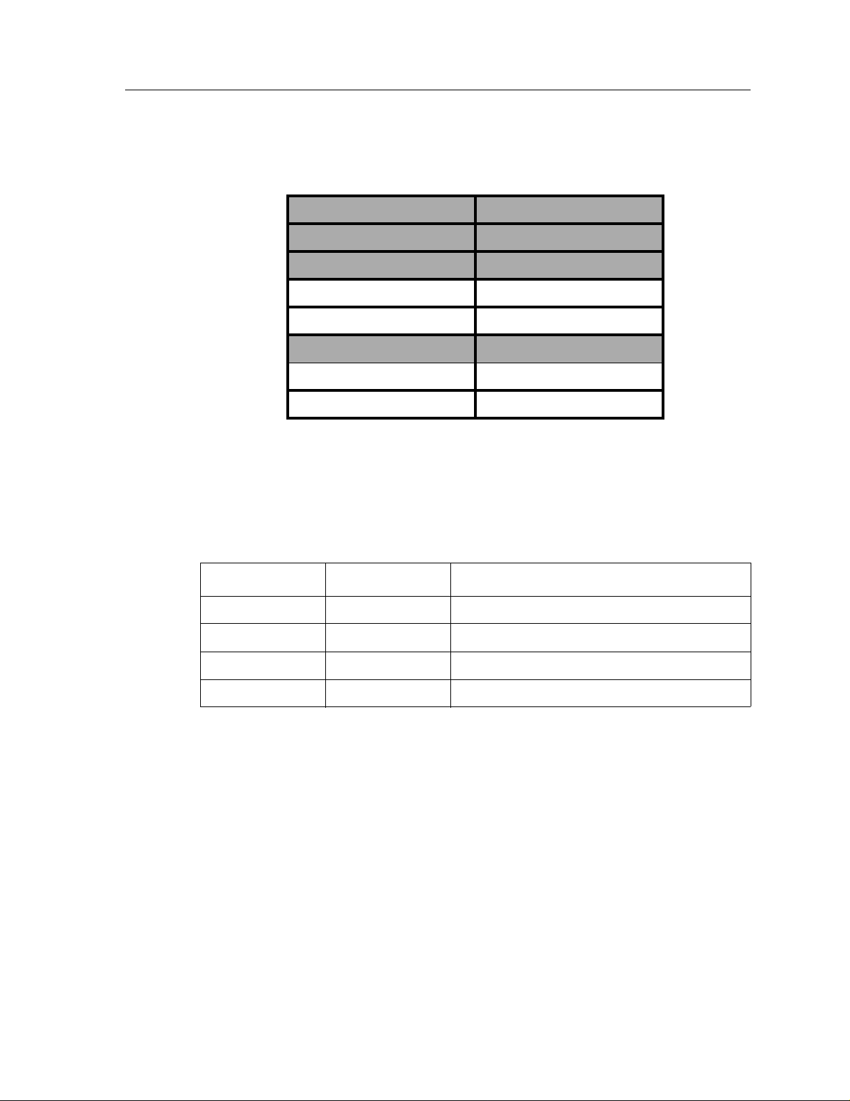
that are not shaded. Notice that Layer-2 is divided into an LLC layer and a MAC layer. The XP2000 operates at the MAC layer but not the LLC layer.
TCP/UDP Services
Features
Layer 7 Application
Layer 6 Presentation
Layer 5 Session
Layer 4 TCP/UDP - application
Layer 3 IP/IPX - routing
Layer 2 LLC
Layer 2 MAC -bridging
Layer 1 Physical Interfaces
The following table lists some well known TCP/UDP services provided by the XP-2000.
Table 2. TCP/UDP services
Features
This section describes the following XP-2000 features:
• Address-based and flow- b ased bri d ging
• Port-based VLANs and protocol-based VLANs
• IP and IPX routing
TCP Port UDP Port Description
23 Telnet
161 SNMP
67 BOOTP/DHCP Relay Agent
520 Routed
• Layer-4 (application) switching
• Security
• Quality of Service (QoS)
Enterasys X-Pedition 2000 Getting Started Guide 3
Page 20

Features
Bridging
• Statistics
• Management
The XP-2000 provides the following types of high-speed bridging:
• Address-based bridging – The XP-2000 performs this type of bridging by looking up the
destination address in an L2 lookup table on the expansion module that receives the bridge
packet from the network. The L2 lookup table indicates the exit port(s) for the bridged packet.
If the packet is addressed to the XP-2000’s own MAC address, the packet is routed rather than
bridged.
• Flow-based bridging – The XP-2000 performs this type of bridging by looking up an entry in
the L2 lookup table containing both the source and destination addresses of the bridge packet.
Your choice of bridging method does not affect XP-2000 performance. However, address-based
bridging is more efficient because it requires fe wer table entries while flow-based bridging pro vides
tighter management and control over bridged traffic.
The XP-2000 ports perform address-based bridging by default, but can be configured to perform
flow-based bridging instead of address-based bridging on a per-port basis. A port cannot be
configured to perform both types of bridging at the same time.
Port and Protocol VLANs
The XP-2000 supports the following types of Virtual LANs (VLANs):
• Port-based VLANs – A port-based VLAN is a set of ports that comprises a Layer-2 broadcast
domain. The XP-2000 confines MAC-layer broadcasts to the ports in the VLAN on which the
broadcast originates. XP-2000 ports outside the VLAN do not receive the broadcast.
• Protocol-based VLANs – A protocol-based VLAN is a named set of ports that comprises an
IP or IPX broadcast domain. The XP-2000 confines IP or IPX broadcasts to the ports within the
IP or IPX based VLAN. Protocol-based VLANs sometimes are called subnet VLANs or Layer3 VLANs.
You can include the same port in more than one VLAN, even in both port-based and protocol-based
VLANs. Moreover, you can define VLANs that span across multiple
XP-2000s. To simplify VLAN administration, the XP-2000 supports 802.1q trunk ports, which
allow you to use a single port to “trunk” traffic from multiple VLANs to another XP-2000 or switch
which supports 802.1q.
Routing
The XP-2000 provides high-speed routing for the following protocols:
4 Enterasys X-Pedition 2000 Getting Started Guide
Page 21

IP Routing
Features
• Internet Protocol (IP) – the protocol switching and routing devices use for moving traffic
within the Internet and within many corporate intranets.
• Internet Packet Exchange (IPX) – a protocol by Novell used in Netware products.
Note: All other protocols that require routing must be tunneled using IP.
By default, the XP-2000 uses one MAC address for all interfaces. The XP-2000 can be configured
to have a separate MAC address for each IP interface and a separate MAC address for each IPX
interface. When the XP-2000 receives a packet whose destination MAC address is one of the XP2000’s IP or IPX interface MAC addresses, the port that received the packet from the network uses
information in the module’s L3 lookup tables (or information supplied by the motherboard) to route
the packet to its IP destination(s).
You can create only one IP and IPX interface on a single port or VLAN. You can add secondary IP
addresses to the same IP interface. When you add an interface to a set of ports, you are adding a
VLAN to those ports. Ports that contain IP and IPX interfaces can still perform Layer-2 bridging.
The XP-2000 supports the following IP unicast routing protocols:
• RIP v1 and RIP v2
• OSPF v2
• BGP v2/v3/v4
IP interfaces do not use a specific routing protocol by default. When you configure an interface for
routing, you also specify the routing protocol the interface will use.
IP Multicast Routing
The XP-2000 supports the following IP multicast routing protocols:
• IGMP v1 and IGMP v2
•DVMRP v3
The XP-2000 does not use a specific IP Multicast routing protocol by default. Configuring an
interface for IP Multicast also specifies its routing protocol.
IPX Routing
The XP-2000 supports the following IPX routing protocols:
•IPX RIP – a version of the Routing Information Protocol (RIP) tailored for IPX
Enterasys X-Pedition 2000 Getting Started Guide 5
Page 22

Features
• IPX SAP – the Service Advertisement Protocol, which allows hosts attached to an IPX network
to reach printers, file servers, and other services
By default, IPX routing is enabled on the XP-2000 when an IPX interface is created.
Layer-4 Switching
In addition to Layer-2 bridging and Layer-3 routing, the XP-2000 performs Layer-4 switching.
Layer-4 switching is based on applications and flows.
• Layer-4 applications – The XP-2000 understands the application for which an IP or IPX packet
contains data and therefore enables you to manage and control traffic on an application basis.
For IP traffic, the XP-2000 looks at the packet’s TCP or UDP port number to determine the
application. For IPX packets, the XP-2000 looks at the destination socket to determine the
application.
• Layer-4 flows – The XP-2000 can store Layer-4 flows in each expansion module. A Layer-4
flow consists of the source and destination addresses in the IP or IPX packet combined with the
TCP or UDP source and destination port number (for IP) or the source and destination socket
(for IPX). You can therefore manage and control individual flows between hosts on an
individual application basis.
Security
A single host can have many individual Layer-4 entries in the XP-2000. For example, an IP host
might have separate Layer-4 application entries for email, FTP, HTTP , and so on, or separate Layer 4 flow entries for specific email destinations and for specific FTP and Web connections.
The bridging, routing, and application (Layer-2, Layer-3, and Layer-4) support described in
previous sections enables you to implement security filters that meet the specific needs of your
organization. You can implement the following types of filters to secure traffic on the XP-2000:
• Layer-2 source filters (block bridge traffic based on source MAC address)
• Layer-2 destination filters (block bridge traffic based on destination MAC address)
• Layer-2 flow filters (block bridge traffic based on specific source-destination pairs)
• Layer-3 source filters (block IP or IPX traffic based on source IP or IPX address)
• Layer-3 destination filters (block IP or IPX traffic based on destination IP or IPX address)
• Layer-3 flow filters (block IP or IPX traffic based on specific source-destination pairs)
• Layer-4 application filters (block traff ic base d on UDP or TCP source and destination ports for
IP or source and destination sockets for IPX)
6 Enterasys X-Pedition 2000 Getting Started Guide
Page 23

Quality of Service
Although the XP-2000 supplies non-blocking high-speed throughput, you can configure the XP2000 to apply Quality of Service (QoS) policies during peak periods to guarantee service to specific
hosts, applications, and flows (source-destination pairs). This is especially useful in networks
where the traffic level can exceed the network medium’s capacity.
The XP-2000 QoS is based on four queues: control , hi gh, medium, and low. Control traffic has the
highest priority, high the second highest, and so on. The default priority for all traffic is low.
You can configure QoS policies for the following types of traffic:
• Layer-2 prioritization (802.1p)
• Layer-3 source-destination flows
• Layer-4 source-destination flows
• Layer-4 application flows
Features
Statistics
The XP-2000 can provide extensive statistical data on demand. You can access the following types
of statistics:
• Layer-2 RMON and MIB II Statistics – Port statistics for normal packets and for errors (packets
in, packets out, CRC errors, and so on)
• Layer-3 RMON v2 Statistics – Statistics for ICMP, IP, IP-interface, IP routing, IP multicast,
VLAN
• Layer-4 RMON v2 Statistics – Statistics for TCP and UDP
Management Platforms
You can manage the XP-2000 using the following management platforms:
• Command Line Interface (CLI) – An EMACs editor -like interface that accepts typed commands
and responds when applicable with messages or tables. You wil l use the CLI to perform the
basic setup procedures described in Chapter 3 of this guide.
• SNMP MIBs and traps – The XP-2000 supports SNMP v1 and many standard networking
MIBs. You can access the XP-2000’s SNMP agent using Enterasys integration software for HP
OpenVie w 5.x on W indows NT or Solaris 2.x, or Enterasys Spectrum on Solaris 2.x. Chapter 3,
Firmware Installation and Setup, in this guide explains how to set up SNMP on the XP-2000.
Enterasys X-Pedition 2000 Getting Started Guide 7
Page 24
Hardware Overview
Hardware Overview
This section describes the XP-2000’s hardware specif ications. Chapter 2, Hardwar e Installation, in
this guide describes how to install the hardware. This section describes the following hardware:
• Chassis and external controls
• Motherboard features
• Power supplies
• Expansion modules
Chassis
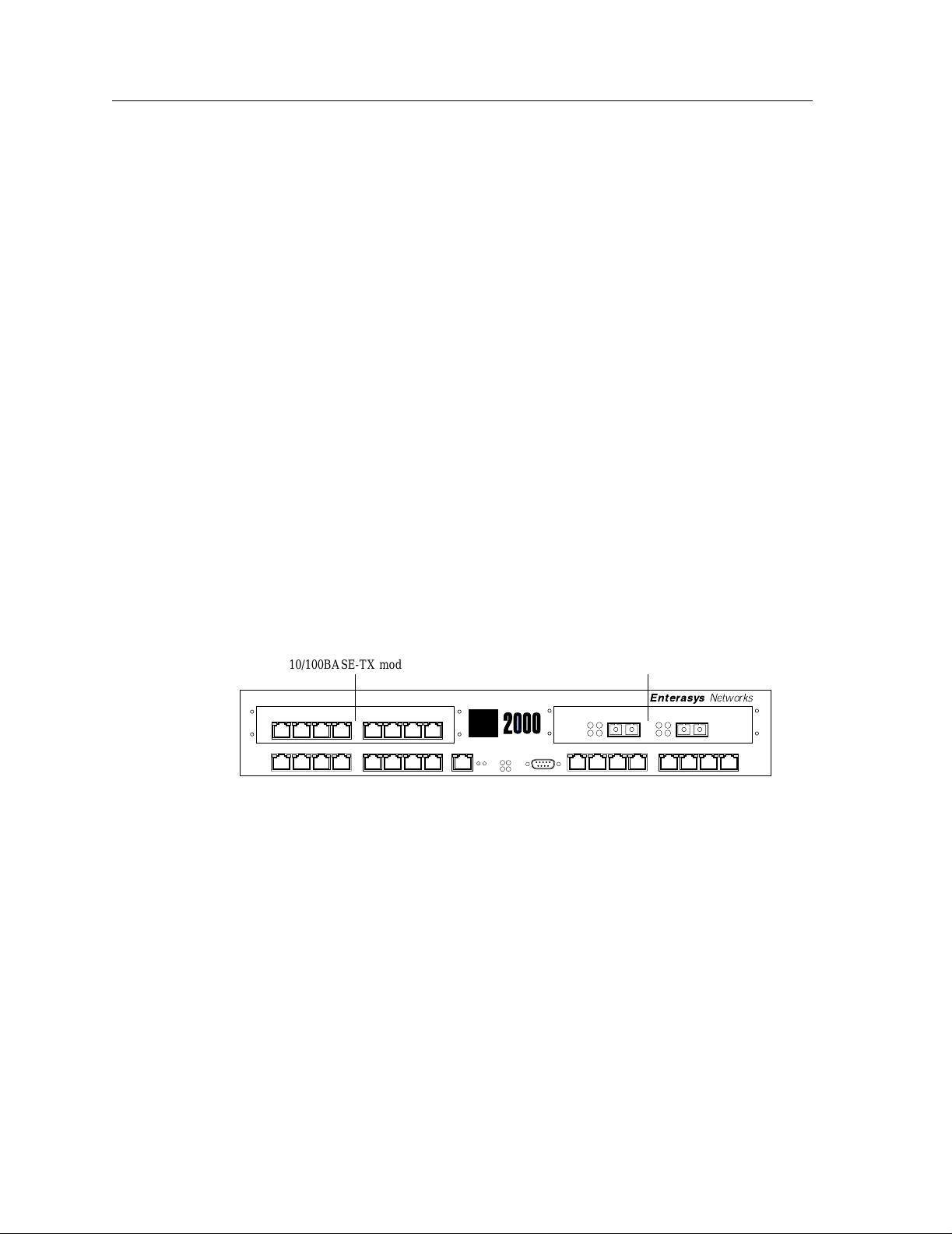
The XP-2000 chassis contains 16 10/100BASE-TX ports and two expansion slots (slots 3 and 4).
Currently, Enterasys configures the XP-2000 at the factory in one of the following ways before
shipping:
• 16 10/100BASE-TX ports and two empty expansion slots
• 24 10/100BASE-TX ports and a 2-port 1000BASE-SX or 1000BASE-LX gigabit module in the
expansion slot
Figure 1 shows the front view of a loaded XP-2000.
10/100BASE-TX module 1000BASE-SX (Gigabit) module
G2M-HTXA2-08 G2M-GSXA1-02
3
10/100BASE-TX 10/100BASE-TX
1
10/100BASE-TX
87654321
87654321 87654321
10/100 MGMT
RST
SYS
OK
ERR DIAG
CONSOLE
HBT
TxRxLink
AN
Enterasys
TxRxLink
Networks
1000BASE-SX
21
AN
4
2
Figure 1. Front view of loaded XP-2000
8 Enterasys X-Pedition 2000 Getting Started Guide
Page 25

External Controls
The XP-2000 has the following external controls. Where appropriate, this guide describes how to
use the controls.
• A Male DB-9 Data Communications Equipment (DCE) port for serial connection from a
• A 10Base-T/100Base-TX Data Terminal Equipment (DTE) port for network connection from a
• A Reset switch (RST). Use this switch to reboot the XP-2000’s motherboard from the internal
•Status LEDs.
Table 3. Status LEDs
LED Label Description
Hardwar e Overview
management terminal. Use this port to establish a direct CLI connection to the
XP-2000. The default baud rate is 9600.
management terminal. The port is configured as Media Data Interface (MDI). Use this port to
establish a management connection to the XP-2000 over a local or bridged Ethernet segment.
boot flash in the event of a system failure. The Reset switch is recessed in the XP-2000’ s chassis,
so you will have to use a tool like a small allen wrench to activate the switch.
OK When this LED is on, the XP-2000 and all expansion modules are functioning
ERR When this LED is on, a fatal system error has occurred. Activate the XP-
HBT This LED flashes when the XP-2000’s boot PROM is active.
DIAG When this LED is on, the XP-2000 is in diagnostic mode. (While in diagnostic
Motherboard Features
The internal “motherboard” performs all the XP-2000’s computing and routing functions. It
contains system-wide bridging and routing tables. Traffic that does not yet have an entry in the L2
and L3/L4 lookup tables on individual expansion modules is handled by the motherboard. After
processing traffic, the motherboard updates the L2 and L3/L4 tables on the ports and/or expansion
slot(s) that received the traffic. The ports/expansion slot(s) thus “learn” about how to forward
traffic.
Boot Flash
The motherboard has a boot flash containing the XP-2000’s boot software and configuration files.
The system software image file resides on an internal flash chip and can be upgraded from a TFTP
server.
correctly.
2000’s boot PROM to reboot the router.
mode, you will notice several other LEDs on the XP-2000 are active, as well.)
Enterasys X-Pedition 2000 Getting Started Guide 9
Page 26

Hardware Overview
RAM Memory
The XP-2000’s motherboard uses 32MB of RAM to hold routing and other tables. This RAM is
“fixed” and is not removable or upgradable.
The XP-2000 uses 128MB of RAM to hold routing and other tables. This RAM is “fixed” and is
not removable or upgradable.
Power Supplies
The XP-2000 uses two power supplies, each delivering 3.3, 5, and 12 volts DC to the motherboard,
internal fans, and other components. Each power supply provides a portion of the power necessary
to operate the XP-2000, with the added bonus that, in the unlikely event that one of the power
supplies should fail, the remaining power supply will assume the entire load and provide enough
current to operate a fully-configured XP-2000 chassis.
Note: Be sure to plug the XP-2000 into a single-phase grounded power source located within 6
The following table lists the specifications for the power supplies.
feet of the installation site.
Fans
Table 4. Power supply voltage and current specifications
Input voltage Input current (maximum)
100-125 VAC 2.6 A
200-240 VAC 1.3 A
The XP-2000 contains two internal fans to provide cooling air flow across the motherboard and
expansion slot(s). The fans are located near the middle of the chassis, between the power supplies
and the motherboard.
Note: To ensure that the fans can provide adequate cooling, Enterasys recommends that you
allow a minimum of 3 inches of clearance on each side of the chassis.
10 Enterasys X-Pedition 2000 Getting Started Guide
Page 27

Expansion Modules
The following expansion modules can be installed in the XP-2000:
• 10/100BASE-TX
• 100BASE-FX
• 1000BASE-SX
• 1000BASE-LX
• Dual Serial (WAN)
• Quad Serial – C (WAN)
• Quad Serial – CE (WAN)
• Dual HSSI (WAN)
10/100BASE-TX Expansion Module
Hardwar e Overview
The 10/100BASE-TX expansion module contains eight independent Ethernet ports. Each port
senses whether it is connected to a 10-Mbps segment or a 100-Mbps segment and automatically
configures itself as a 10Base-T or 100Base-TX port. Figure 2 shows the front panel of the
10/100BASE-TX expansion module.
Link LED Activity LED
10/100BASE-TXG2M-HTXA2-08
87654321
10Base-T/100Base-TX ports
Figure 2. Front panel of 10/100BASE-TX expansion module
Enterasys X-Pedition 2000 Getting Started Guide 11
Page 28

Hardware Overview
Cabling and Connector Specifications
The following table lists the media specifications for the 10/100BASE-TX expansion module.
Table 5. 10/100BASE-TX expansion module specifications
10Base-T • 802.3 standard
100Base-TX • 802.3u standard
Port Type Specification
• RJ-45 connector wired as Media Data Interface Crossed (MDIX); see
10/100BASE-TX Expansion Module on page 34 for pin assignmen ts
• EIA Category 3, 4, or 5 unshielded twisted pair cabling
• Maximum 328 feet (100 meters) segment length
• RJ-45 connector wired as Media Data Interface Crossed (MDIX); see
10/100BASE-TX Expansion Module on page 34 for pin assignmen ts
• EIA Category 5 unshielded twisted pair cabling
• Maximum 100 meters (328 feet) segment length
LEDs
The 10/100BASE-TX expansion module uses the following LEDs.
Table 6. 10/100BASE-TX expansion module LEDs
LED Description
Link Each port has two LEDs on its connector. The green LED on the left side of
the connector indicates the link status. When this LED is lit, the port
hardware is detecting that a cable is plugged into the port and the port has
established communication with the device at the other end.
Activity The amber LED on the right side of each port connector flashes each time
the port’s transceiver sends or receives packets.
12 Enterasys X-Pedition 2000 Getting Started Guide
Page 29

100BASE-FX Expansion Module
The 100BASE-FX expansion module provides the same features as the 10/100BASE-TX
expansion module but uses multimode fiber-optic cable (MMF) to connect to the network. Figure 3
shows the front panel of the 100BASE-FX expansion module.
G2M-HFXA4-08 100BASE-FX
Figure 3. Front panel of 100BASE-FX expansion module
Note: A hardware restriction prevents the X-Pedition 2000 from supporting configurations
consisting of:
– Two (2) Gigabit modules.
– Two (2) 100Base-FX modules.
1
2345678
Lnk Act Lnk Act Lnk Act Lnk Act Lnk Act Lnk Act Lnk Act Lnk Act
Hardwar e Overview
However , the router does support a configuration consisting of one (1) Gigabit module and
one (1) 100Base-FX module.
Cabling and Connector Specifications
The following table lists the media specifications for the 100BASE-FX expansion module.
Table 7. 100BASE-FX expansion module specifications
Port type Specification
100Base-FX • 80 2.3u standard
• SC-style Media Interface Connector (MIC); either connection pin in
the MIC can be used for transmit or receive.
• 62.5 micron multimode fiber-optic cable
• Maximum 412 meters (1352 feet) segment length for half-duplex links
• Maximum 2 kilometers (6562 feet) segment length for full-duplex
links
Enterasys X-Pedition 2000 Getting Started Guide 13
Page 30

Hardware Overview
LEDs
The 100BASE-FX expansion module uses the following LEDs.
Table 8. 100BASE-FX expansion module LEDs
LED Description
Lnk Each port has two LEDs located to the left of the connector. The
Act The amber Act LED flashes each time the port’s transceiver sends or
1000BASE-SX Expansion Module
The 1000BASE-SX expansion module contains two independent Gigabit (1000-Mbps) Ethernet
ports. The ports connect to multimode-mode fiber (MMF) cables. Figure 4 shows the front panel of
the 1000BASE-SX expansion module.
green Lnk LED indicates the link status. When this LED is lit, the
port hardware is detecting that a cable is plugged into the port and the
port has established communication with the device at the other end.
receives packets.
1000BASE-SXG2M-GSXA1-02
Tx Link
AN
Rx
Gigabit port Gigabit port
Tx Link
Rx
21
AN
Figure 4. Front panel of 1000BASE-SX expansion module
14 Enterasys X-Pedition 2000 Getting Started Guide
Page 31

Hardwar e Overview
Cabling and Connector Specifications
The following table lists the media specifications for the 1000BASE-SX expansion module.
Table 9. 1000BASE-SX expansion module specifications
Port type Specification
1000Base-SX • 802.3z standard (also uses 802.3x for flow control)
• SC-style Media Interface Connector (MIC)
• 62.5 micron or 50 micron multimode fiber-optic cable
• Maximum 275 meters (902 feet) segment length for 62.5 micron
fiber-optic cable, based on installed fiber bandwidth
• Maximum 550 meters (1804 feet) segment length for 50 micron fiberoptic cable, based on installed fiber bandwidth
LEDs
The 1000BASE-SX expansion module uses the following LEDs.
Table 10. 1000BASE-SX expansion module LEDs
LED Description
Per-port Link • Green – indicates that the port hardware detects a cable plugged into the
port and a good link is established.
• Red (intermittent) – indicates that the port received an error during
operation.
• Red (solid) – indicates that the port hardware detects a cable plugged
into the port, however, a bad link is established.
• Off – indicates that no link from exists with the port.
Per-port Rx • Green – indicates when the port’s transceiver receives packets.
• Orange – indicates when the port’s transceiver receives flow-control
packets.
Per-port Tx • Green – indicates when the port’s transceiver transmits packets.
• Orange – indicates when the port’s transceiver transmits flow-control
packets.
Enterasys X-Pedition 2000 Getting Started Guide 15
Page 32

Hardware Overview
Table 10. 1000BASE-SX expansion module LEDs (Continued)
LED Description
Per-port AN • Green – indicates that the expansion module is autonegotiating the
1000BASE-LX Expansion Module
The 1000BASE-LX expansion module provides the same features as the 1000BASE-SX expansion
module, and supports both single-mode fiber (SMF) and MMF. Figure 5 shows the front panel of
the 1000BASE-LX expansion module.
operating mode of the link between full-duplex and half-duplex.
• Orange (intermittent) – indicates that autonegotiation is in process.
• Orange (solid) – indicates a problem with autonegotiation configuration.
• Red – indicates an autonegotiation failure. This fault may occur if the
link partner does not support full duplex.
• Off – indicates that autonegotiation has been disabled or the link is
down.
1000BASE-LXG2M-GLXA9-02
Tx Link
AN
Rx
Gigabit port Gigabit port
Tx Link
AN
Rx
21
Figure 5. Front panel of 1000BASE-LX expansion module
16 Enterasys X-Pedition 2000 Getting Started Guide
Page 33

Hardwar e Overview
Cabling and Connector Specifications
The following table lists the media specifications for the 1000BASE-LX expansion module.
Table 11. 1000BASE-LX expansion module specifications
Port type Specification
1000Base-LX • 802.3z standard (also uses 802.3x for flow control)
• SC-style Media Interface Connector (MIC)
• 62.5 micron or 50 micron multimode fiber-optic cable
• 9.5 micron single-mode fiber-optic cable
• Maximum 550 meters (1804 feet)
1
segment length for 62.5 micron
fiber-optic cable, based on installed fiber bandwidth
• Maximum 550 meters (1804 feet) segment length for 50 micron fiberoptic cable, based on installed fiber bandwidth
• Maximum 5 kilometers (229,659 feet) segment length for 10 micron
single-mode fiber-optic cable
1. Patch cord required.
LEDs
The 1000BASE-LX expansion module uses the following LEDs.
Table 12. 1000BASE-LX expansion module LEDs
LED Description
Per-port Link • Green – indicates that the port hardware detects a cable plugged into the
port and a good link is established.
• Red (intermittent) – indicates that the port received an error during
operation.
• Red (solid) – indicates that the port hardware detects a cable plugged
into the port, however, a bad link is established.
• Off – indicates that no link from exists with the port.
Per-port Rx • Green – indicates when the port’s transceiver receives packets.
• Orange – indicates when the port’s transceiver receives flow-control
packets.
Enterasys X-Pedition 2000 Getting Started Guide 17
Page 34

Hardware Overview
Table 12. 1000BASE-LX expansion module LEDs (Continued)
Per-port Tx • Green – indicates when the port’s transceiver transmits packets.
Per-port AN • Green – indicates that the expansion module is autonegotiating the
LED Description
• Orange – indicates when the port’s transceiver transmits flow-control
packets.
operating mode of the link between full-duplex and half-duplex.
• Orange (intermittent) – indicates that autonegotiation is in process.
• Orange (solid) – indicates a problem with autonegotiation configuration.
• Red – indicates an autonegotiation failure. This fault may occur if the
link partner does not support full duplex.
• Off – indicates that autonegotiation has been disabled or the link is
down.
Dual Serial and Quad Serial – C/CE Expansion Modules
The Dual Serial expansion module contains a single dual serial WAN port (two serial ports located
on one high density connector). The Quad Serial – C and Quad Serial – CE expansion modules
each contain two dual serial WAN ports. In addition, the Quad Serial – C expansion module
includes compression, and the Quad Serial – CE expansion module includes compression and
encryption, for each WAN port. Figure 6 shows the front panel of the Dual Serial WAN expansion
module.
12
Link
Rx
Tx
1,2
Figure 6. Front panel of Dual Serial WAN expansion module
Dual SerialG2M-SERAC-02
18 Enterasys X-Pedition 2000 Getting Started Guide
Page 35

Hardwar e Overview
Figure 7 shows the front panel of the Quad Serial WAN expansion module.
Quad Serial - CG2M-SECAC-04
12
Link
Rx
Tx
1,2
34
Link
Rx
Tx
3,4
Figure 7. Front panel of Quad Serial – C/C E WAN expansion module
Cabling and Connector Specifications
The following table lists the media specifications for the Dual Serial and Quad
Serial – C/CE expansion modules.
Table 13. Dual Serial and Quad Serial – C/CE WAN expansion module specifications
Port Type Specification
Dual serial • V.35, X.21, EIA530, EIA530A, or RS449
• LFH-60 high density connector; see Dual Serial and Quad Serial –
C/CE Expansion Modules on page 38 for pin assignments
• Recommended 3 meters (10 feet) segment length for standard WAN
expansion module-to-CSU/DSU data port.
1. Connector cables for WAN expansion modules may be ordered from Enterasys Networks. For detailed
information, including part numbers, see Dual Serial and Quad Serial – C/CE Expansion Modules
1
on page 38.
LEDs
The Dual Serial and Quad Serial – C/CE expansion modules use the following LEDs.
Table 14. Dual Serial and Quad Serial – C/ CE WAN expansion module LEDs
LED Description
Per-port Link Indicates that the expansion module detects a cable plugged into the port
and a good link is established.
Per-port Rx Indicates when the port’s transceiver receives data.
Per-port Tx Indicates when the port’s transceiver transmits data.
Enterasys X-Pedition 2000 Getting Started Guide 19
Page 36

Hardware Overview
Dual HSSI Line Card
The Dual HSSI line card contains two 50-pin High Speed Serial Interface (HSSI) ports. Figure 8
shows the front panel of the Dual HSSI WAN line card.
G8M-HSIAC-02
Offline
Online
Link
Rx
Tx
Link
Rx
Tx
Dual HSSI
Hot
Swap
Figure 8. Front panel of Dual HSSI WAN line card
Cabling and Connector Specifications
The following table lists the media specifications for the Dual HSSI line card.
Port Type Specification
HSSI • HSSI rev 2.11
• 50-pin High Speed Serial Interface (HSSI) connector; see Dual HSSI Line
Card on page 40 for pin assignments
• Recommended 3 meters (10 feet) segment length for standard WAN line
card-to-CSU/DSU data port.
1. Connector cables for WAN line cards may be ordered from Enterasys Networks. For detailed information,
including part numbers, see Dual HSSI Line Card
on page 40.
1
LEDs
The Dual HSSI line card uses the following LEDs.
LED Description
Offline When lit, this amber LED on the left side of the line card indicates that the
line card is offline (powered off) but is ready for hot swap.
The Offline LED also is lit briefly during a reboot or reset of the XP but
goes out as soon as the control module discovers the line card.
Online When lit, this green LED indicates that the line card is online and is ready to
receive, process, and send packets if configured to do so.
20 Enterasys X-Pedition 2000 Getting Started Guide
Page 37

Hardwar e Overview
LED Description
Link Indicates that the line card detects a cable plugged into the port and a good
link is established.
Rx Indicates when the port’s transceiver receives data.
Tx Indicates when the port’s transceiver transmits data.
Enterasys X-Pedition 2000 Getting Started Guide 21
Page 38

Hardware Overview
22 Enterasys X-Pedition 2000 Getting Started Guide
Page 39

Chapter 2
Hardware
Installation
This chapter provides hardware installation information and procedures in the following sections:
• Safety considerations
• Hardware specifications
• Installing the hardware
If the hardware is already installed and you are ready to install the software and perform basic
system configuration, see Chapter 3, Firmware Installation and Setup.
Safety Considerations
Read the following safety warnings and product cautions to avoid personal injury or product
damage.
Preventing Injury
Observe the following safety warnings to prevent accidental injury when working with the XP2000 hardware.
• To avoid back strain, be careful when lifting the XP-2000 out of the shipping box.
• Never attempt to rack mount the XP-2000 unaided. Ask an assistant to help you hold the XP-
2000.
• Before performing any upgrade or installation procedures, ensure that the XP-2000 is powered
off.
Enterasys Xpedition 2000 Getting Started Guide 23
Page 40

Hardwar e Specifications
• Never operate the XP-2000 with exposed expansion slots.
• Never operate the XP-2000 if the it becomes wet or the area where it has been installed is wet.
Preventing Equipment Damage
Observe the precautions listed in this section to prevent accidental damage to the
XP-2000 components.
Caution: To prevent accidental product damage, observe the following precautions:
• Always use proper electrostatic discharge (ESD) gear when handling expansion modules or
other internal parts of the chassis.
• Make sure you allow adequate room for air flow around the XP-2000.
Hardware Specifications
The following table lists the physical and environmental specifications for the XP-2000.
Table 15. XP-2000 physical and environmental specifications
Dimensions Inches: 2.8” (height) x 17” (width) x 18.5” (depth)
Weight Pounds: 22
Power 100-125 VAC, 4 A maximum;
Operating temperature Fahrenheit: 41
Installing the Hardware
This section describes how to perform the following tasks:
• Verifying your shipment
Centimeters: 7.1cm x 43.2cm x 47cm
Kilograms: 10
200-240 VAC, 2 A maximum
48-60 V DC, 4.65 A maximum
o
F to 104oF
Centigrade: 5
o
C to 40oC
• Installing the chassis (on a tabletop or in an equipment rack)
• Installing expansion modules
24 Enterasys Xpedition 2000 Getting Started Guide
Page 41

• Attaching console management cables
• Attaching port cables
Verifying Your Shipment
Before you begin installing your XP-2000, check your shipment to ensure that ev erything you
ordered arrived securely. Ente rasys assembles the XP-2000 according to one of the configurations
described in Chassis on page 8 before shipping.
Open the shipping box(es) and verify that you received the following equipment:
• An XP-2000, power cord(s), and a console cable. The console cable is used for connecting a
terminal to the XP-2000’s console port.
• One copy of the Enterasys Xpedition 2000 Getting Started Guide (the book you are reading
now).
• Rack mount kit, including two rack mounting brackets and fastening screws.
Depending on your order, your shipment will also contain the expansion modules you ordered.
Installing the Hardware
Enterasys Xpedition 2000 Getting Started Guide 25
Page 42

Installing the Hardware
Installing the Chassis
Enterasys recommends that only qualified personnel conduct installation of any XP chassis.
Warning: Before performing any upgrade or installation procedures, ensure that the
XP-2000 is powered off.
This section contains procedures for the following types of installation:
• Table-top installation
• Rack mount installation
Table-Top Installation
You can instal l the XP-20 00 on a tabletop.
1. Select a table that is stable (not wobbly) and is not in an area subject to frequent foot traffic.
Remember that you will be attaching numerous cables to the XP-2000.
2. Place the XP-2000 on the table, allowing at least 3” of space on each side for adequate air flow
to the cooling fans.
Rack Mount Installation
You can install the XP-2000 in a standard 19” equipment rack. The XP-2000 chassis contains screw
holes for front-mounting brackets.
Note: Never attempt to rack mount the XP-2000 unaided. Ask an assistant to help you hold the
chassis.
To install the XP-2000 chassis in an equipment rack, use the following procedure. You need a
phillips-head screwdriver to perform this procedure.
Figure 9 shows an example of how to install the XP-2000 in an equipment rack. The procedure
following the figure describes how to install the XP-2000 in an equipment rack.
26 Enterasys Xpedition 2000 Getting Started Guide
Page 43

Installing the Hardware
G2M-HTXA2-08 G2M-GSXA1-02
3
10/100BASE-TX 10/100BASE-TX
1
10/100BASE-TX
87654321
87654321 87654321
10/100 MGMT
RST
SYS
OK
HBT
ERR DIAG
CONSOLE
Enterasys
Link
Rx AN
Networks
1000BASE-SX
Tx
LinkTx
21
Rx AN
4
2
Figure 9. Installing the XP-2000 chassis in an equipment rack
To install the XP-2000 in an equipment rack:
1. If your XP-2000 is not already equipped with rack-mounting brackets, take the following
steps. Otherwise skip to step 2.
a. Align one of the mounting brackets over the correspon ding holes in the side of the XP-
2000. The mounting bracket is correctly positioned when the side with two open mounting
holes is flush with the front of the XP-2000.
b. Use the phillips-head screwdriver and the supplied phillips-head screws to attach the
mounting bracket to both the side and bottom of the chassis. (There are four holes for each
rack mounting bracket—the one on the side of the chassis that you exposed in step a, and
three holes in the bottom of the chassis.)
Note: Be sure to use the phillips-head screws supplied by Enterasys. If you use screws
that are longer than the ones included with your shipment, there is a danger of
damaging the XP-2000‘s internal components.
c. Attach the other mounting bracket.
2. Along with an assistant, lift the XP-2000 into place in the mounting rack.
3. While your assistant holds the chassis in place, use the phillips-head screwdriver and four
phillips-head screws to attach the mounting brackets to the mounting rack.
Caution: Make sure the screws are tight before your assistant releases the chassis. If you
accidentally leave the screws loose, the chassis can slip and fall, possibly becoming damaged.
Enterasys Xpedition 2000 Getting Started Guide 27
Page 44

Installing the Hardware
Connecting Power to the Chassis
AC
To attach the unit to AC power, simply plug the chassis into a grounded power source. For
information about the AC power requirements, see Hardware Specifications on page 24.
DC
T o attach the unit to the DC power supply, connect the ground, negative, and positive leads to their
respective terminals at the rear of the unit. For information about the DC power requirements, see
Hardware Specifications on page 24.
Installing an Expansion Module
Warning: Before performing any upgrade or installation procedures, ensure that the
XP-2000 is powered off and that you are properly “grounded” to avoid electrostatic discharge
while working inside the XP-2000’s chassis.
Note: A hardware restriction prevents the Xpedition 2000 from supporting configurations
consisting of:
– Two (2) 1000Base-SX or 1000Base-LX Gigabit modules.
– Two (2) 100Base-FX modules.
However , the router does support a configuration consisting of one (1) Gigabit module and
one (1) 100Base-FX module.
To install a 1000BASE-SX or 1000BASE-LX gigabit expansion module:
1. Ensure that the XP-2000 is powered off.
2. If your XP-2000 is equipped for rack mounting, use the phillips-head screwdriver to remove
the mounting brackets from each side of the XP-2000.
3. Take off the XP-2000’s top cover.
a. Use the phillips-head screwdriver to remove the four mounting screws (two on each side
of the router, front and back) that hold the top cover on the XP-2000.
Enterasys
Networks
3
10/100BASE-TX 10/100BASE-TX
1
87654321 87654321
10/100 MGMT
RST
SYS
OK
ERR DIAG
CONSOLE
HBT
4
2
Figure 10. Removing the XP-2000’s cover
28 Enterasys Xpedition 2000 Getting Started Guide
Page 45

Installing the Hardware
b. Slide the cover away from the front of the XP-2000 about 1/2”, then lift it away from the
XP-2000.
4. Use the phillips-head screwdriver to remove the four mounting screws in the existing face
plate or cover plate corresponding to the expansion slot where you plan to install the
1000BASE-SX or 1000BASE-LX gigabit expansion module. Be sure not to damage or remove
the conductive tape on the inside of the chassis, both above and below the expansion slot
opening.
blank expansion module face plate
Enterasys
Networks
4
Figure 11. Removing a face plate or cover plate (view from outside chassis)
5. From the inside of the chassis, line up the four holes in the expansion module’ s face plate with
the corresponding holes around the empty expansion slot in the chassis, and use the phillipshead screwdriver to tighten the screws (from the front) on each side of the expansion module’ s
face plate to affix it to the chassis.
Note: You will probably have to gently push the expansion card’s face plate down while
lining up the first of the screws. The grounding fingers for the 10/100BASE-TX
module that sits immediately below the empty expansion slot protrude upwards to
make contact with the bottom of the face plate.
Networks
Figure 12. Installing the new face plate (view from inside chassis)
Note: There are two different types of face plates for the expansion modules. There is a
regular face place and an EMI extended face plate. Shown below is a picture of the
EMI extended face plate:
Enterasys Xpedition 2000 Getting Started Guide 29
Enterasys
Page 46

Installing the Hardware
Figure 13. EMI extended face plate
Front of XP-2000
Additional
Screw Hole
on Face Plate
Align Slots Over
Stand-offs on
Mother Board.
Figure 14. Installing the EMI extended face plate (view from inside chassis)
6. Insert the 1000BASE-SX or 1000BASE-LX gigabit expansion module from the top and ensure
that it makes maximum surface contact with its face plate.
7. Line up the two screw holes at the back of the expansion module and connect
the stacking connector at the back of the expansion module to the pins on the
XP-2000’s motherboard.
30 Enterasys Xpedition 2000 Getting Started Guide
Page 47

Installing the Hardware
Caution: The female and male connectors for the expansion modules are not keyed, so it is possible
to misalign the connection. Ensure that all pins fit properly into the female connector on the
expansion module before applying power to the XP-2000.
8. Use the phillips-head screwdriver to tighten all six screws that will hold the expansion module
in place in the XP-2000’s chassis.
Note: There are two additional screws that are required with the EMI extended face plate as
shown below:
9
*
*
These two screws are
*
used only with extended
EMI face plate
G2M-HTXA2-08 G2M-GSXA1-02
3
10/100BASE-TX 10/100BASE-TX
1
10/100BASE-TX
87654321
10/100 MGMT
87654321 87654321
RST
SYS
OK
HBT
ERR DIAG
CONSOLE
Rx AN
Figure 15. Installing a 1000BASE-SX or 1000BASE-LX gigabit expansion module
9. Replace the XP-2000’s cover.
When you are ready to attach the segment cables, use the procedures in Attaching Port Cables on
page 34.
Attaching the Console Management Cables
The XP-2000 has two ports for attaching management consoles to the XP-2000.
Link
Enterasys
Tx
LinkTx
Rx AN
Networks
21
1000BASE-SX
8
7
4
2
• A male DB-9 DCE port for direct serial connection from a terminal. Use this port to perform
basic setup, including setting up the XP-2000 for management through the network using the
CLI or SNMP.
Enterasys Xpedition 2000 Getting Started Guide 31
Page 48

Installing the Hardware
• An RJ-45 10/100Base-T DTE port for Telnet connection from a host on the network. The port
is configured for Media Data Interface (MDI). You use this port to manage the XP-2000 using
the CLI or SNMP.
Connecting to the Serial Port
Figure 16 shows where to plug in the cable to the XP-2000’s serial port. The procedure following
the figure describes how to set up and insert the cable.
G2M-HTXA2-08 G2M-GSXA1-02
3
10/100BASE-TX 10/100BASE-TX
1
10/100BASE-TX
87654321
10/100 MGMT
87654321 87654321
RST
SYS
OK
ERR DIAG
CONSOLE
HBT
TxRxLink
AN
Enterasys
TxRxLink
Networks
1000BASE-SX
21
AN
4
2
Figure 16. Plugging into the XP-2000’s serial (DB-9 DCE) port
To attach the supplied console cable to the XP-2000’s DB-9 port:
1. Locate the console cable included with the XP-2000 chassis. The console cable is a female to
female DB-9 crossover cable that has the following pin assignments:
Table 16. DB-9 connector pin assignments
Signal (XP-2000 port) Pin Signal (management console port)
Unused 1 Unused
TXD (transmit data) 2 RXD (receive data)
a
RXD (receive data) 3 TXD (transmit data)
Unused 4 Unused
GND (ground) 5 GND (ground)
Unused 6 Unused
32 Enterasys Xpedition 2000 Getting Started Guide
Page 49

Installing the Hardware
Table 16. DB-9 connector pin assignments
Signal (XP-2000 port) Pin Signal (management console port)
CTS (clear to send) 7 CTS (clear to send)
RTS (request to send) 8 RTS (request to send)
Unused 9 Unused
a. The left hand column pin assignments are for the male DB-9 connector on the XP-2000. Thus, pin 2 (TXD or
“transmit data”) must emerge on the management console’ s end of th e connection as RXD (“receive data”) and
so on.
2. Plug one end of the console cable into the XP-2000’s DCE DB-9 port.
3. Plug the other end of the console cable into the management console’s DTE port.
4. When you are ready to begin configuring the XP-2000, use procedures in Chapter 3, Firmware
Installation and Setup, to power on the switch and boot the software. You will perform initial
setup by entering CLI commands on the management console.
Connecting to the 10/100Base-TX Port
Use the RJ-45 10/100Base-TX DTE port for Telnet connection from a host on the network. The
port is configured for Media Data Interface (MDI). Figure 17 shows where to plug in to the XP2000’s 10/100Base-TX port. The procedure following the figure describes how to set up and insert
the cable.
G2M-HTXA2-08 G2M-GSXA1-02
3
10/100BASE-TX 10/100BASE-TX
1
Figure 17. Plugging into the XP-2000’s 10/100Base-TX port
10/100BASE-TX
87654321
87654321 87654321
10/100 MGMT
RST
SYS
OK
ERR DIAG
CONSOLE
HBT
TxRxLink
Enterasys
TxRxLink
AN
AN
21
Networks
1000BASE-SX
4
2
To attach a cable to the 10/100Base-TX port:
Enterasys Xpedition 2000 Getting Started Guide 33
Page 50

Installing the Hardware
1. Obtain a cable with an RJ-45 connector that has the following pin assignments:
Table 17. RJ-45 connector pin assignments
Signal (XP-2000 port) Pin Signal (management console port)
TXD (transmit data) 1 RXD (receive data)
a
TXD (transmit data) 2 RXD (receive data)
RXD (receive data) 3 TXD (transmit data)
Unused 4 Unused
Unused 5 Unused
RXD (receive data) 6 TXD (transmit data)
Unused 7 Unused
Unused 8 Unused
a. The right hand column pin assignments are for the RJ-45 connector on the XP-2000. Thus, pin 1 (TXD or
“transmit data”) must emerge on the management console’ s end of th e connection as RXD (“receive data”) and
so on.
2. Make sure the TXD signals from the XP-2000 emerge as RXD signals on the management
console and the TXD signals from the management console emerge as RXD signals on the XP-
2000.
3. After ensuring that the pin assignments on both ends of the connection are correct, plug the
appropriate end of the connection into the XP-2000’s RJ-45 10/100Base-TX port.
4. Plug the other end of the connection into the management console’s port.
5. When you are ready to begin configuring the XP-2000, use procedures in Chapter 3, Firmware
Installation and Setup, to power on the switch and boot the software. You will perform initial
setup by entering CLI commands on the management console.
Attaching Port Cables
The following sections describe how to connect the XP-2000 to your network.
10/100BASE-TX Expansion Module
Figure 18 illustrates plugging your 10Base-T or 100Base-TX cable into a 10/100BASE-TX port.
The procedure following the figure explains how to set up and insert the cable.
34 Enterasys Xpedition 2000 Getting Started Guide
Page 51

Installing the Hardware
G2M-HTXA2-08 G2M-GSXA1-02
3
10/100BASE-TX 10/100BASE-TX
1
10/100BASE-TX
87654321
87654321 87654321
10/100 MGMT
RST
SYS
OK
ERR DIAG
CONSOLE
HBT
TxRxLink
AN
Enterasys
TxRxLink
AN
21
Networks
1000BASE-SX
4
2
Figure 18. Plugging an ethernet cable into a 10/100BASE-TX port
T o attach segment cables to your 10/100BASE-TX ports:
1. For all the 10/100-Mbps ports, obtain copper cables that have the following pin assignments.
The RJ-45 connectors on the 10/100 ports are configured as Media Data Interface Crossed
(MDIX). You can use Category 3 (Cat-3) or higher wire for 10-Mbps segments. For 100-Mbps
segments, use Cat-5 or higher wire. The ports automatically sense to which type of segment
they are connected and configure themselves to transmit and receive at the appropriate
bandwidth.
Table 18. RJ-45 connector pin assignments
Signal (XP-2000 port) Pin Signal (connected device port)
TXD (transmit data) 1 RXD (receive data)
a
TXD (transmit data) 2 RXD (receive data)
RXD (receive data) 3 TXD (transmit data)
Unused 4 Unused
Unused 5 Unused
RXD (receive data) 6 TXD (transmit data)
Unused 7 Unused
Unused 8 Unused
a. The right hand column pin assignments are for the RJ-45 connector on the XP-2000. Thus, pin 1 (TXD or
“transmit data”) must emerge on the management console’ s end of th e connection as RXD (“receive data”) and
so on.
Enterasys Xpedition 2000 Getting Started Guide 35
Page 52

Installing the Hardware
Figure 19 shows the pin positions in the 10/100BASE-TX connectors.
2. Make sure the TXD signal from the port emerges as an RXD signal on the switch, router, or
host on the other end of the segment cable. Likewise, make sure the TXD signal from the port
emerges as an RXD signal on the other end of the segment.
3. Plug one end of the cable into the port and the other end of the cable into the device at the other
end of the connection.
100BASE-FX Expansion Module
87654321
Figure 19. 10/100B ASE-TX RJ-45 connector
The 100BASE-FX expansion module supports multimode fiber (MMF). Figure 20 shows where to
plug your fiber cable into a port on the 100BASE-FX expansion module.
The procedure following the figures describes how to set up and insert the cables.
G20-B
G2M-HTXA2-08 G2M-HFXA4-08
3
10/100BASE-TX 10/100BASE-TX
1
10/100BASE-TX
87654321
87654321 87654321
10/100 MGMT
RST
SYS
OK
ERR DIAG
CONSOLE
HBT
Lnk
3
Act
Lnk
Lnk
Act
Lnk
Enterasys
Lnk
4
Act
Lnk
21
Networks
100BASE-FX
Lnk
87
Act
Lnk
5
6
4
2
Figure 20. Plugging an ethernet cable into a 100BASE-FX expansion module port
The 100BASE-FX expansion module uses SC-style Media Interface Connectors (MICs) to attach
to multimode fiber (MMF) cables.
T o attach the segment cables to your 100BASE-FX expansion module, obtain an MMF cable with
an SC MIC and plug the MIC into the port connector. When you plug the other end of the cable into
another device, ensure that the cable connected to the transmit port on the XP is connected to the
receive port on the other device. The receive port on the XP should be connected to the transmit
port on the other device.
36 Enterasys Xpedition 2000 Getting Started Guide
Page 53

Note: A hardware restriction prevents the Xpedition 2000 from supporting configurations
consisting of:
– Two (2) 1000Base-SX or 1000Base-LX Gigabit modules.
– Two (2) 100Base-FX modules.
However , the router does support a configuration consisting of one (1) Gigabit module and
one (1) 100Base-FX module.
1000BASE-SX and 1000BASE-LX Expansion Modules
The 1000BASE-SX expansion module supports multimode fiber (MMF), and the
1000BASE-LX expansion module supports single-mode fiber (SMF) as well as MMF. Figure 21
shows how to plug your fiber cable into a port on the 1000BASE-SX or 1000BASE-LX expansion
module. The procedure following the figure describes how to set up and insert the cables.
Installing the Hardware
G2M-HTXA2-08 G2M-GSXA1-02
3
10/100BASE-TX 10/100BASE-TX
1
10/100BASE-TX
87654321
87654321 87654321
10/100 MGMT
RST
SYS
OK
ERR DIAG
CONSOLE
HBT
TxRxLink
AN
Enterasys
TxRxLink
AN
21
Networks
1000BASE-SX
4
2
Figure 21. Plugging an ethernet cable into a 1000BASE-SX or 1000BA SE-LX expansion
module
The 1000BASE-SX and 1000BASE-LX expansion modules use SC-style Media Interface
Connectors (MICs) to attach to SMF and/or MMF cables.
T o attach the segment cables to your 1000BASE-SX or 1000BASE-LX expansion module, obtain a
SMF and/or MMF cable with an SC MIC and plug the MIC into the port connector. When you plug
the other end of the cable into another device, insure that the cable connected to the transmit port on
the XP-2000 is connected to the receive port on the other device. The receive port on the XP-2000
should be connected to the transmit port on the other device.
Note: A hardware restriction prevents the Xpedition 2000 from supporting configurations
consisting of:
– Two (2) 1000Base-SX or 1000Base-LX Gigabit modules.
– Two (2) 100Base-FX modules.
However , the router does support a configuration consisting of one (1) Gigabit module and
one (1) 100Base-FX module.
Enterasys Xpedition 2000 Getting Started Guide 37
Page 54

Installing the Hardware
Dual Serial and Quad Serial – C/CE Expansion Modules
The Dual Serial and Quad Serial – C/CE expansion modules each use the same 60-pin LFH-60
high density connector to link to their respective Channel Service Units/Data Service Units
(CSU/DSUs). Figure 23 on page 39 shows how to plu g your serial cable into a port on the Dual
Serial or Quad Serial – C/CE expansion modules.
Enterasys offers the following four cables, used to connect the XP to standard CSU/DSU modules:
Table 19. Enterasys dual serial port to CSU/DSU connector cables
Enterasys Part Number CSU/DSU Connector Type Standard
SYS-SV35-DTE Two (2) V.35 34-pin connectors
a
V.3 5
SYS-S530-DTE Two (2) DB-25 25-pin connectors EIA-530
SYS-S449-DTE Two (2) DB-37 37-pin connectors RS-449
SYS-SX21-DTE Two (2) DB-15 15-pin connectors X.21
a. The two remote ends of each type of connector cable is labeled “Port A” and “Port B”. “Port A” corresponds to
Port 1 on a Dual Serial WAN expansion module and Port 1 or 3 on a
Quad Serial – C/CE, depending upon which WAN expansion module port you are using. Similarly, “Port B”
corresponds to Port 2 on a Dual Serial WAN expansion module and Port 2 or 4 on a Quad Serial – C/CE.
Note: Because the LFH-60 high density connectors on Dual Serial and Quad
Serial – C/CE expansion modules contain two serial WAN ports per interface, all four
cable types defined above feed two CSU/DSU ports.
Table 20 maps the pin assignments for Enterasys’ LFH-60 high density connectors for the Dual
Serial and Quad Serial – C/CE expansion modules.
Table 20. LFH-60 high density connector pin assignments
Pin Signal Pin Signal Pin Signal Pin Signal
1 P1_GND 16 P2_TXC_A 31 P1_GND 46 P2_TXD_A
2 P1_MODE[2] 17 P2_TXC_B 32 P1_MODE[0] 47 P2_TXD_B
3 P1_CTS_B 1 8 P2_DCD_A 33 P1_DCD_B 4 8 P2_RTS_A
4 P1_CTS_A 19 P2_DCD_B 34 P1_DCD_A 49 P2_RTS_B
5 P1_RTS_B 20 P2_MODE[1] 35 P0_RXD_B 50 P2_DSR_A
6 P1_RTS_A 21 P2_GND 36 P0_RX D_A 51 P2_DSR_B
7 P1_SCTE_B 22 P2_GND 37 Reserved 52 P2_LL_A
8 P1_SCTE_A 23 P1_TXD_A 38 P2_GND 53 P2_SHIELD
38 Enterasys Xpedition 2000 Getting Started Guide
Page 55

Installing the Hardware
Table 20. LFH-60 high density connector pin assignments (Continued)
Pin Signal Pin Signal Pin Signal Pin Signal
9 P1_GND 24 P1_TXD_B 39 P2_MODE[0] 54 Reserved
10 P2_GND 25 P1_TXC_A 40 P2_CTS_B 55 P1_RXC_A
11 P2_MODE[2] 26 P1_TXC_B 41 P2_CTS_A 56 P1_RXC _B
12 P2_RXD_B 27 P1_DSR_A 42 P2_DTR_B 57 P1_DTR_A
13 P2_RXD_A 28 P1_DSR_B 43 P2_DTR_A 58 P1_DTR_B
14 P2_RXC_B 29 P1_MODE[1] 44 P2_SCTE_B 59 P1_LL_A
15 P2_RXC_A 30 P1_GND 45 P2_SCTE_A 60 P1_SHIELD
Figure 22 shows the pin positions in the LFH-60 high density connector.
1
30
31
60
15
16
45
46
Figure 22. LFH-60 high density connector
The procedure following the figure describes how to set up and insert the cables.
G2M-HTXA2-08 G2M-SERCAC-04
3
10/100BASE-TX 10/100BASE-TX
1
10/100BASE-TX
87654321
10/100 MGMT
87654321 87654321
RST
SYS
OK
ERR DIAG
CONSOLE
HBT
12
Link
Rx
Tx
1,2
Enterasys
4
3
Link
Rx
Tx
Figure 23. Plugging a LFH-60 high density connector cable into a Dual Serial or
Quad Serial – C/CE expansion module
3,4
Networks
Quad Serial - C
4
2
Enterasys Dual Serial and Quad Serial – C/CE expansion modules use standard copper twisted-pair
cable with one of four custom remote-end connectors to attach to their respective CSU/DSU
modules.
Enterasys Xpedition 2000 Getting Started Guide 39
Page 56

Installing the Hardware
To attach the segment cables to your Dual Serial or Quad Serial – C/CE expansion module:
1. Obtain one of the for Enterasys connector cables described in Table 19 on page 38 and connect
the single LFH-60 high density connector to the XP WAN interface you wish to use.
2. Plug the remote end of the connector for each port you wish to use into its respective
CSU/DSU data port.
Dual HSSI Line Card
The Dual HSSI line card uses a 50-pin High Speed Serial Interface (HSSI) connector to link to a
Channel Service Unit/Data Service Unit (CSU/DSU). Enterasys offers a 3 meter (10 foot) 50-pin
HSSI connector cable (part number SYS-HSSI-CAB) to connect Dual HSSI line cards to remote
CSU/DSU modules.
The following table maps the pin assignments for Enterasys’s 50-pin HSSI connector for the Dual
HSSI line card.
Pin Signal Pin Signal Pin Signal Pin Signal
1 GND 14 (reserved) 26 GND 39 (reserved)
2 RT+ 15 (reserved) 27 RT- 40 (reserved)
3 CA+ 16 (reserved) 28 CA- 41 (reserved)
4 RD+ 17 (reserved) 29 RD- 42 (reserved)
5 LC+ 18 (reserv e d) 30 LC- 43 (reserved)
6 ST+ 19 GND 31 ST- 44 GND
7 GND 20 (reserved) 32 GND 45 (reserved)
8 TA+ 24 (reserved) 33 TA- 46 (reserved)
9 TT+ 22 (reserved) 34 TT- 47 (reserved)
10 LA+ 23 (reserved) 35 LA- 48 (reserved)
11 SD+ 24 (reserved) 36 SD- 49 (reserved)
12 LB+ 25 GND 37 LB- 50 GND
13 GND 38 GND
Note: Because neither connector at the ends of the SYS-HSSI-CAB cable is keyed, you can
simply plug either end of the cable into either your Dual HSSI line card or the remote
HSSI CSU/DSU data port.
40 Enterasys Xpedition 2000 Getting Started Guide
Page 57

Figure 24 shows the pin positions in the 50-pin HSSI connector.
Installing the Hardware
25
1
2650
Figure 24. 50-pin HSSI connector
The Enterasys Dual HSSI line card uses standard copper twisted-pair cable with identical
50-pin HSSI connectors at each end to attach to a CSU/DSU module.
To attach the segment cables to your Dual HSSI line card:
1. Obtain a Enterasys 50-pin HSSI connector cable (part number SYS-HSSI-CAB) and connect
either end of the HSSI connector cable to the XP WAN interface you wish to use.
2. Plug the remote end of the connector cable into the HSSI CSU/DSU data port you wish to use.
Enterasys Xpedition 2000 Getting Started Guide 41
Page 58

Installing the Hardware
42 Enterasys Xpedition 2000 Getting Started Guide
Page 59

Chapter 3
Firmware
Installation and
Setup
This chapter provides the following firmware installation and basic setup procedures:
• Powering on and booting the firmware
• Starting the Command Line Interface (CLI)
• Setting basic system information
• Setting up SNMP community strings
• Setting up passwords
• Setting the DNS domain name and address
• Setting SYSLOG parameters
• Loading system image firmware
• Loading the boot PROM firmware
• Activating configuration changes and saving the configuration file
Powering On and Booting the Firmware
To power on the XP-2000 and boot the firmware:
1. Make sure any exposed expansion slots are free of foreign objects, such as tools or your hands,
and are covered with coverplates.
Enterasys X-Pedition 2000 Getting Started Guide 43
Page 60

Starting the Command Line Interface
2. Plug the XP-2000’s power supplies into a power source. If the power source is acti ve, the
router will automatically power on and attempt to boot using the Boot Firmware image in the
motherboard’s boot flash. As it boots, the router performs a minimal hardware check and
searches for a valid System Firmware image. If a valid image is av ailable, it is loaded onto the
router and booted up. As the firmware boots, the management console attached to the
XP-2000’s DB-9 DCE port displays messages related to the phases of the boot sequence The
Boot Firmware then transfers control of the router to the System Firmware and the CLI is
activated. When the firmware is fully booted, the following message appears on the
management console:
Press RETURN to activate console...
3. Press Return (or Enter) to activate the CLI on the console.
Starting the Command Line Interface
To start the Command Line Interface (CLI), power on the system. Startup messages appear on the
console (the terminal attached to one of the XP-2000’s ports).
After the firmware is fully booted and you press Return (or Enter) to activate the CLI, the CLI
prompts you for a password. You can define separate passwords for Login access, Enable mode,
and Configure mode. The factory default password for these is set to blank. (Simply press Return.)
Access Modes
The CLI has the following access modes:
• User – Allows you to display basic information and use basic utilities such as ping but does not
allow you to display SNMP, filter and access control list information, or make other
configuration changes. Y ou can tell you are in User mode when the command prompt ends with
a “
• Enable – Allows you to display SNMP, filter, and access control information as well as all the
information you can display in User mode. To enter Enable mode, enter the enable command,
then supply the password when prompted. When you are in Enable mode, the command prompt
ends with a “
• Configure – Allows you to make configuration changes. To enter Configure mode, first enter
Enable mode (enable command), then enter the configure command from the Enable command
prompt. When you are in Configure mode, the command prompt ends with “
• Boot – This mode appears when the XP-2000 or the system image is not found during bootup.
You should enter the reboot com mand to reset the router. If the XP-2000 still fails to bootup,
please call Enterasys Technical Support.
>” character.
#“ character.
(config)#.”
Note: The command prompt will show the name of the XP-2000 in front of the mode
character(s). The default name is “xp.” The procedure in Setting Basic System
Information on page 46 describes how to change the system name.
44 Enterasys X-Pedition 2000 Getting Started Guide
Page 61

When you are in Configure or Enable mode, use the exit command or press Ctrl+Z to exit to the
previous access mode.
Note: When you exit Configure mode, the CLI will ask you whether you want to activate the
configuration commands you have issued. If you enter yes or y, the configuration
commands you issued are placed into effect and the XP-2000’s configuration is changed
accordingly. However, the changes are not written to the Startup configuration file in the
XP-2000’s boot flash and therefore are not reinstated after a reboot. See Activating
Configuration Changes and Saving the Configuration File on page 60 for information
about saving configuration changes.
Basic Line Editing Commands
The CLI supports EMACs-like line editing commands. The following table lists some commonly
used commands. For a complete set of commands, see the The T eraLink 2000 Series Library: User
Reference.
Table 21. Some commonly used CLI commands
Key sequence Command
Starting the Command Line Interface
Ctrl+A Move cursor to beginning of line
Ctrl+B Move cursor back one character
Ctrl+D Delete character
Ctrl+E Move cursor to end of line
Ctrl+F Move cursor forward one character
Ctrl+N Scroll to next command in command history (use the cli show history
command to display the history)
Ctrl+P Scroll to previous command in command history
Ctrl+U Erase entire line
Ctrl+X Erase from cursor to end of line
Ctrl+Z Exit current access mode to previous access mode
Enterasys X-Pedition 2000 Getting Started Guide 45
Page 62

Setting Basic System Information
Setting Basic System Information
Use the procedure in this section to set the following system information:
• System time and date
• System name
• System location
• Contact name (the person to contact regarding this XP-2000)
Note: Some of the commands in this procedure accept a string value. String values can be up a
maximum of 255 characters in length, including blank spaces. Surround strings that
contain blanks with quotation marks (example:
To set the system information:
1. Ensure that you are in Enable mode by entering the enable command in the CLI.
2. Use the following commands to set the system time and date and then verify the setting
“string with internal blanks”).
set date year <number> month <month-name> day <day> hour <hour> minute <minute>
<second>
second
system show date
Here is an example:
xp# system set date year 2001 month may day 15 hour 11 minute 54 second 0
Time changed to: Mon May 14 11:54:00 2001
xp# system show date
Current time: Mon May 14 11:54:04 2001
3. Ensure that you are in Configure mode by entering the configure command in the CLI. The
commands in Step 4 through Step 10 can be entered only from Configure mode.
4. Use the following commands to set the system name, location, and contact information:
system set name
system set location “
system set contact “
“<string>”
<string>”
<string>”
Here is an example:
xp(config)# system set name “xp-1”
xp(config)# system set location “Sunnyvale, CA”
xp(config)# system set contact “John Smith”
46 Enterasys X-Pedition 2000 Getting Started Guide
Page 63

Setting Basic System Information
5. Use the interface add ip command to set the IP address and netmask for the en0 Ethernet
interface, as shown in the following example:
xp(config)# interface add ip en0 address-netmask 10.50.11.22/16
Note: The en0 interface is automatically created by the system and is reserved for the
XP-2000’s management port.
6. To show the changes accumulated in the scratchpad, enter the show command while in
Configure mode, as shown in the following example:
xp(config)# show
-EDIT-I-NOCONFIG, the running system has no configuration
******** Non-committed changes in Scratchpad ********
1*: system set name “xp-1”
2*: system set location “Sunnyvale, CA”
3*: system set contact “John Smith”
When you enter commands in Configure mode, the XP-2000 does not immediately execute the
commands. Instead, the XP-2000 checks the syntax of the commands and if they are
syntactically correct, stores them in a temporary scratchpad in memory. The scratchpad is
automatically cleared when you log out of the XP, so you must activate the changes and then
save them to the Startup configuration file to retain the changes, as explained below.
The scratchpad allows you to make configuration changes without worrying about the order in
which you issue the commands. Also, if you change your mind about configuration changes you
are making, you do not need to incrementally back out of the changes. You can simply choose
not to activate them. As you become more familiar with the XP-2000 and the CLI and begin to
make detailed configuration changes, you may find the scratchpad quite useful. For simple
changes such as the ones in this procedure, you might instead want to activate the changes as
you go, then use CLI commands to view the results of the changes.
7. Enter the save active command to activate commands, such as the “system set...” commands
you used in Step 4, in the scratchpad.
If you exit Configure mode (by entering the exit command or pressing Ctrl+Z) before activating
any of your changes in the scratchpad, the CLI will ask you whether you want to make the
changes in the scratchpad active by displaying the following message:
Do you want to make the changes Active [yes]?
8. Enter yes or y to activate the changes.
Enterasys X-Pedition 2000 Getting Started Guide 47
Page 64

Setting Up SNMP Community Strings
9. To display the active configuration, enter the system show active-config command, as shown
in the following example:
xp-1# system show active-config
Running system configuration:
!
! Last modified from Console on Mon May 15 11:55:35 200
!
1 : system set name “xp-1”
2 : system set location “Sunnyvale, CA”
3 : system set contact “John Smith”
Changes in the active configuration take effect on the running system but will not be restored
following a reboot.
10. To ensure that changes are restored following a reboot, you must sav e the activ e database to the
Startup configuration file by taking the following steps:
a. Enter the exit command to return to Enable mode.
b. Enter the copy active to startup command.
The CLI displays the following message:
Are you sure you want to overwrite the Startup configuration [no]?
11. Enter yes or y to add the active configuration to the Startup configuration file.
Note: You also can save active changes to the Startup configuration file from within Configure
mode by entering the save startup command.
See Activating Configuration Changes and Saving the Configuration File on page 60 for more
information about the scratchpad, active database, and Startup configuration.
Setting Up SNMP Community Strings
To use SNMP to manage the XP-2000, you need to set up an SNMP community on the XP-2000.
Otherwise, the XP-2000’s SNMP agent runs in local trap process mode until you disable it using
the snmp stop command. In addition, if you want to be able to access the SNMP traps issued by the
XP-2000’s SNMP agent, you need to specify the IP address of the target for the SNMP traps.
To add the SNMP community string and specify the target for traps, take the following steps:
1. Ensure that you are in Enable mode by entering the enable command in the CLI.
2. Ensure that you are in Configure mode by entering the configure command in the CLI.
48 Enterasys X-Pedition 2000 Getting Started Guide
Page 65

Setting Up SNMP Community Strings
3. Use the following commands to add an SNMP community string and set a target for the traps.
snmp set community <community-name> privilege read
snmp set target
<IP-addr> community <community-name>
Note: The target IP address must be locally attached to the XP-2000. You cannot specify a
target that is connected to the XP-2000 by another router. If the IP address is more
than one hop away from the XP-2000, configure the
XP-2000 with a static route to the target so that a cold start trap is sent.
4. Enter the show command to examine the changes accumulated in the scratchpad.
5. Enter the save active command to activate the commands you entered in the previous steps.
6. To verify the changes, enter the snmp show all command.
Enterasys X-Pedition 2000 Getting Started Guide 49
Page 66

Setting Up SNMP Community Strings
Here is an example of the commands and output for configuring SNMP and saving the changes.
xp-1# config
xp-1(config)# snmp set community public privilege read-only
xp-1(config)# snmp set target 10.50.11.12 community public
xp-1(config)# save ac tive
xp-1(config)# exit
xp-1# snmp show all
SNMP Agent status:
enabled mode
SNMP Last 2 Clients:
10.50.100.53 Mon May 14 10:31:27 2001
10.50.100.43 Mon May 14 10:31:22 2001
SNMP Chassis Identity:
not configured.
Trap Table:
Index Trap Target Addr Community String Status
----- none configured -----
Traps by Type:
Authentication trap: enabled
Link Up/Down trap: enabled
Community T a ble:
Index Community String Privilege
1. public READ-WRITE
SNMP statistics:
247019 packets received
246346 get requests
745 get-next requests
184 get-bulk requests
50 set requests
0 bad SNMP versions
1 bad community names
0 ASN.1 parse errors
0 PDUs too big
247018 packets sent
246346 get responses
745 get-next responses
184 get-bulk responses
50 set responses
7. After verifying the SNMP configuration, save the changes to the Startup configuration file by
entering the copy active to startup command.
Remember to enter yes or y when the CLI asks you whether you want to overwrite the Startup
configuration.
50 Enterasys X-Pedition 2000 Getting Started Guide
Page 67

Setting Up Passwords
You can password protect CLI access to the XP-2000 by setting up passwords for login access and
Enable access. Users who have a login pas sword but not an Enable password can use only the
commands available in User mode. Users with an Enable passw ord can use the commands a vailable
in Enable and Configure modes as well as the commands in User mode.
In addition, you can set up the XP-2000 for TACACS and/or RADIUS authentication on login and
password by a TACACS or RADIUS server. You can find a section describing configuration of the
XP-2000 for TACACS and RADIUS in the The Te raLink 2000 Series Library: User Reference.
Note: If a password is configured for Enable mode, the XP-2000 prompts you for the password
when you enter the enable command. Otherwise, the XP-2000 displays a message
advising you to configure an Enable password before entering Enable mode. From Enable
mode, you can access Configure mode to make configuration changes.
The default password for each access level is blank. (Simply press Enter or Return without entering
a password.) If you want to add password protection to the CLI, use the following procedure.
1. Ensure that you are in Enable mode by entering the enable command in the CLI.
Setting Up Passwords
2. Ensure that you are in Configure mode by entering the configure command in the CLI.
3. Use the following command for each password you want to set:
system set password login|enable <string>|none
4. Enter the show command to examine the changes accumulated in the scratchpad.
5. Enter the save active command to activate the commands.
6. Enter the system show active-config command to verify the active changes.
Here is an example of the commands in the previous steps:
xp-1(config)# system set password login demo
xp-1(config)# system set password enable demo
xp-1(config)# save active
xp-1# exit
xp-1# system show active-config
Running system configuration:
!
! Last modified from Console on Mon May 14 12:12:19 2001
!
1 : system set name “xp-1”
2 : system set location “Sunnyvale, CA”
3 : system set contact “John Smith”
4 : system set hashed-password login jNIssH c976b667e681d03ccd5fc527f219351a
5 : system set hashed-password enable zcGzbO 5d1f73d2d478ceaa062a0b5e0168f46a
6 : snmp set community public privilege read
7 : snmp set target 10.50.11.12 community public
Enterasys X-Pedition 2000 Getting Started Guide 51
Page 68

Setting the DNS Domain Name and Address
Caution
: Test all the new passwords before saving the active configuration to the Startup
configuration file. As shown in the example above, the passwords are shown in the active
configuration in an encrypted format and will also appear this way in the Startup configuration.
To keep your passwords secure, the XP-2000 does not have a command for displaying passwords.
If you forget a password, you can remove the password by entering the following command while
in Configure mode. (See the Enterasys X-Pedition Command Line In terface Ref erence Manual for
more information.)
system set password login|enable none
Setting the DNS Domain Name and Address
If you want the XP-2000 to be able to access a DNS server, use the following procedure to specify
the domain name and IP address for the DNS server.
1. Ensure that you are in Enable mode by entering the enable command in the CLI.
2. Use the following command to verify that the XP-2000 can reach the DNS server by pinging
the server, as shown in the following example:
xp-1# ping 10.50.11.12
PING 10.50.11.12 (10.50.11.12): 56 data bytes
64 bytes from 10.50.11.12: icmp_seq=0 ttl=255 time=0 ms
--- 10.50.11.12 ping statistics ---
1 packets transmitted, 1 packets received, 0% packet loss
round-trip min/avg/max = 0/0/0 ms
3. Ensure that you are in Configure mode by entering the configure command in the CLI.
4. If you have not done so already, use the interface add ip command to set the IP address and
netmask for the en0 Ethernet interface, as shown in the following example:
xp-1(config)# interface add ip en0 address-netmask 10.50.11.22/16
Note: The en0 interface is automatically created by the system and is reserved for the
XP-2000’s management port.
5. Use the following command to specify the domain name for which the DNS server(s) have
authority:
system set dns domain
where <domain-name> is your specified domain name (example:
<domain-name>
mktg.company.com).
52 Enterasys X-Pedition 2000 Getting Started Guide
Page 69

Setting SYSLOG Parameters
6. Use the following command to “add” one or more DNS servers to the XP-2000:
system set dns server ["]<IP-address> [<IP-address>] [<IP-address>]["]
where <IP-address> is the IP address of the DNS server. You can specify up to three DNS
servers.
Note: If you specify more than one IP address, you must separate the addresses with a space
and surround them with a single pair of quotes. You do not need to surround a single
IP address with quotes.
7. Enter the save active command to activate the commands and enter yes or y to activate the
changes.
Here is an example of the commands above featuring the addition of two DNS server IP
addresses:
xp-1# config
xp-1(config)# system set dns domain “mktg.company.com”
xp-1(config)# system set dns server “10.50.11.12 10.50.12.11"
xp-1(config)# save active
8. Enter the system show dns com mand to verify the new DNS settings, as shown in the
following example:
xp-1# system show dns
DNS domain: mktg.company.com, DNS server(s): 10.50.11.12 10.50.12.11
9. Use the ping command to verify that the XP-2000 can resolve the DNS server name into its IP
address, as shown in the following example:
xp-1# ping xp1
PING xp-1.mktg.company.com (10.50.11.12): 56 data bytes
64 bytes from 10.50.11.12: icmp_seq=0 ttl=255 time=0 ms
--- xp-1.mktg.company.com ping statistics --1 packets transmitted, 1 packets received, 0% packet loss
round-trip min/avg/max = 0/0/0 ms
Setting SYSLOG Parameters
The CLI can use SYSLOG messages to communicate the following types of messages to a
SYSLOG server:
• Fatal – Provide information about events that caused the XP-2000 to crash and reset.
• Error – Provide information about errors.
Enterasys X-Pedition 2000 Getting Started Guide 53
Page 70

Setting SYSLOG Parameters
• Warning – Provide warnings against invalid configuration information and other conditions
that are not necessarily errors. This is the default.
• Informational – Provide informational messages such as status messages. The SYSLOG
messages that the XP-2000 displays while booting the firmware and reading the startup
configuration file are examples of Informational messages.
The XP-2000 writes the SYSLOG messages to a SYSLOG daemon on UDP port 514. You can set
the CLI to send all or only some of the message types. By default, the CLI sends warning, error, and
fatal messages but not informational messages to the specified SYSLOG server.
54 Enterasys X-Pedition 2000 Getting Started Guide
Page 71

Setting SYSLOG Parameters
Use the following procedure to specify the SYSLOG server and the types of messages you want the
CLI to log on the server.
1. Ensure that you are in Enable mode by entering the enable command in the CLI.
2. Use the following command to verify that the XP-2000 can reach the SYSLOG server by
pinging the server:
ping <IP-addr>
3. Ensure that you are in Configure mode by entering the configure command in the CLI.
4. If you have not already done so, use the interface add ip command to set the IP address and
netmask for the en0 Ethernet interface, as shown in the following example:
xp-1(config)# interface add ip en0 address-netmask 10.50.11.22/16
Note: The en0 interface is automatically created by the system and is reserved for the
XP-2000’s management port.
5. Use the following commands to “add” the SYSLOG server to the XP-2000, set the message
level, and set the SYSLOG facility:
system set syslog server <hostname-or-IP-addr>
system set syslog level fatal|error|warning|info
system set syslog facility <facility-type>
Here is an example:
xp-1# config
xp-1(config)# system set syslog server 10.50.11.12
xp-1(config)# system set syslog level info
xp-1(config)# system set syslog facility local0
Enterasys X-Pedition 2000 Getting Started Guide 55
Page 72

Loading System Image Firmware
6. Enter the show command to show the commands you just entered. Because you have not
activated these conf iguration cha nges yet, they are listed in the scratchpad section of the
output. Here is an example:
xp-1(config)# show
Running system configuration:
!
! Last modified from Console on Mon May 14 12:37:21 2001
!
1 : interface add ip en0 address-netmask 10.50.11.22/16
!
2 : system set dns server 10.50.11.12
3 : system set dns domain mktg.company.com
4 : system set name "xp-1"
5 : system set location "Sunnyvale, CA
6 : system set contact "John Smith"
7 : system set hashed-password login jNIssH c976b667e681d03ccd5fc527f219351a
8 : system set hashed-password enable zcGzbO 5d1f73d2d478ceaa062a0b5e0168f46a
!
9 : snmp set community public privilege read
10 : snmp set target 10.50.11.12 community public
******** Non-committed changes in Scratchpad ********
1*: system set syslog server 10.50.11.12
2*: system set syslog lev el info
3*: system set syslog facility local0
Note: The other configuration changes made during this CLI session are also listed. Active
changes are listed in the “Running system configuration section” and unactivated
changes are listed in the “Non-committed changes in Scratchpad” section.
7. To activate the SYSLOG commands, enter the save active command.
Loading System Image Firmware
The XP-2000 operates using the system image firmware installed in its internal flash chip. To
upgrade the system firmware and operate using the upgraded image, go through the following
procedure:
1. Display the current boot settings by entering the system show version command, as shown in
the following example:
xp-1# system show version
Software Information
Software Version : E9.0.5.0
Copyright : Copyright (c) 2002 Enterasys Networks
Image Information : Version E9.0.5.0, built on Tue Aug 27 17:15:01 2002
Image Boot Location: slot0:boot:/E9050-image/
Boot Prom Version : prom-E3.2.0.0
Note: In this example, the location “slot0” indicates that the XP-2000 is set to use the
factory-installed system firmware in the motherboard’s internal flash chip.
56 Enterasys X-Pedition 2000 Getting Started Guide
Page 73

Loading System Image Firmware
2. Copy the firmware upgrade you want to install onto a TFTP server that the XP-2000 can
access. (Use the ping command to verify that the XP can reach the TFTP server.)
3. Use the following command to copy the firmware upgrade onto the internal flash chip in the
XP-2000:
system image add <IPaddr-of-TFTP-host> <image-file-name>
Here is an example:
xp-1# system image add tftp-server 10.50.11.12 fi le-name /images/E9050-image
Downloading image '/images/E9050-image' from host '10.50.11.12'
to local image E9050-image (takes a while) . . .
download: done
save:
kernel: 100%
images/ssr_wan: 100%
images/ssr_are: 100%
images/ssr_fddi: 100%
images/ssr_atm155_sar: 100%
images/ssr_atm155_fpga_400: 100%
done
Image checksum validated.
%SYS-I-BOOTADDED, Image 'E9050-image' added.
4. Enter the system image list command to verify that the new image exists on the internal flash
chip, as shown in the following example:
xp-1# system image list
Images currently available on Master CM:
E9050-image (version E9.0.5.0)
**W arning: No local image is selected for next reboot on this CM.
Consider using the 'system image choose <imagename>' command
to choose an image for this CM. If you do not, the XP will
attempt to boot by first searching the bootsource variable in nvram.
When this variable is not set, you will be sent to the boot prom prompt.
When this variable is set, the XP will attempt to boot from the image set.
If this fails, the XP will search for a single image on the flash.
If a single image is found, the XP will use it to boot.
But if a single image is not found (perhaps no images are
on the flash or perhaps more than one image is on the flash)
the XP will send you to the boot prom prompt.
5. Use the following command to select the image file th e XP-2000 will use the next time you
reboot the switch.
system image choose
<file-name>
Enterasys X-Pedition 2000 Getting Started Guide 57
Page 74

Loading System Image Firmware
Here is an example:
xp-1# system image choose E9050-image
Making image E9050-image (version E9.0.5.0) the active image
for next reboot on Master CM . . .
%SYS-I-CHS_PRIMARY_OK, image successfully chosen on Primary CM
6. Enter the system image list command to verify the change.
xp-1# system image list
Images currently available on Master CM:
E9050-image (version E9.0.5.0) [selected for next boot]
Note: You do not need to activate this change.
58 Enterasys X-Pedition 2000 Getting Started Guide
Page 75

Loading Boot PROM Firmware
The XP boots using the boot PROM firmware installed in the XP-2000’s internal memory. To
upgrade the boot PROM firmware and boot using the upgraded image, use the following procedure.
Note: X-Pedition routers use two versions of the boot PROM Firmware—one for the XP-2000
line and another for the X-Pedition 8000/8600 and ER16 lines. When you install a new
boot PROM image, check the version before you begin. Installing the incorrect image may
cause serious problems.
1. Display the current boot settings by entering the system show version command, as shown in
the following example:
xp-1# system show version
Software Information
Software Version : 4.0.0.0
Copyright : Copyright (c) 2001 Enterasys Networks
Image Information : Version 4.0.0.0, built on Mon May 14 01:16:15 2001
Image Boot Location: tftp://10.50.89.88/xp2000
Boot Prom Version : prom-1.1.0.0
Loading Boot PROM Firmware
Note: In this example, the location “pc-flash” indicates that the XP-2000 is set to use the
factory-installed firmware in the motherboard’s internal flash chip.
2. Copy the firmware upgrade you want to install onto a TFTP server that the XP-2000 can
access. (Use the ping command to verify that the XP can reach the TFTP server.)
3. Use the following command to copy the boot PROM upgrade into the XP-2000’s internal
memory:
system promimage upgrade <IPaddr-of-TFTP-host> <image-file-name>
Here is an example:
xp-1# system promimage upgrade 10.50.11.12 prom2
Downloading image 'prom-1.1.0.0' from host '10.50.11.12'
to local image prom-1.1.0.0 (takes about 3 minutes)
kernel: 100%
Image checksum validated.
Image added.
4. Enter the system show version command to verify that the new boot PR OM f irmware is on the
internal memory of the XP-2000.
Enterasys X-Pedition 2000 Getting Started Guide 59
Page 76

Upgrading the VFS
Upgrading the VFS
A VFS file system called VFS2 is available. VFS2 dramatically decreases the time required for
deleting and adding system images.
Note: Upgrading the file system to VFS2 will not erase your configuration image.
The VFS2 file system is only compatible with:
• boot PROM version v.1.1.0.8
• system image version 3.1 or later
To upgrade the VFS file system to VFS2, perform the following steps:
1. Upgrade the firmware to release version 3.1 or later.
2. Upgrade the bootprom to version v.1.1.0.8. See Loa ding Boot PROM Firmware on page 59 for
instructions on upgrading the firmware.
3. Reboot.
4. Press esc during bootup to enter the bootprom mode.
5. Type pcmakeversion2 to convert your old VFS1 flash card into a new VFS2 file system.
6. Reboot.
Activating Configuration Changes and Saving the Configuration File
The XP-2000 uses three special configuration files:
• Active – The commands from the Startup configuration file and any configuration commands
that you have made active from the scratchpad (see below).
Caution: The active configuration remains in effect only during the current power cycle. If you
power down or reboot the XP-2000 without saving the active configuration changes to the Startup
configuration file, the changes are lost.
• Startup – The configuration file that the XP-2000 uses to configure itself when the system is
powered on.
• Scratchpad – The configuration commands you have entered during a management session.
These commands do not become active until you explicitly activate them. Because some
commands depend on other commands for successful execution, the XP-2000 scratchpad
simplifies system configuration by allowing you to enter conf iguration commands in any order ,
even when dependencies exist. When you activate the commands in the scratchpad, the
XP-2000 sorts out the dependencies and executes the command in the proper sequence.
60 Enterasys X-Pedition 2000 Getting Started Guide
Page 77

Activating Configuration Changes and Saving the Configuration File
Activating the Configuration Commands in the Scratchpad
The configuration commands you have entered using procedures in this chapter are in the
Scratchpad but have not yet been activated. Use the following procedure to activate the
configuration commands in the scratchpad:
1. Ensure that you are in Enable mode by entering the enable command in the CLI.
2. Ensure that you are in Configure mode by entering the configure command in the CLI.
3. Enter the save active command.
If you exit Configure mode (by entering the exit command or pressing Ctrl+Z) before activating
any of your changes in the scratchpad, the CLI will ask you whether you want to make the
changes in the scratchpad active by displaying the following message:
Do you want to make the changes Active [yes]?
4. Enter yes or y to activate the changes.
Saving the Active Configuration to the Startup Configuration File
After you save the configuration commands in the scratchpad, the XP-2000 executes the commands
and makes the corresponding configuration changes. However, if you power down or reboot the
XP-2000, the new changes are lost. Use the following procedure to save the changes into the
Startup configuration file so that the XP-2000 reinstates the changes when you reboot the firmware.
1. Ensure that you are in Enable mode by entering the enable command in the CLI.
2. Enter the copy active to startup command to copy the configuration changes in the Active
configuration to the Startup configuration.
The CLI displays the following message:
Are you sure you want to overwrite the Startup configuration [no]?
3. Enter yes or y to save the changes.
Note: You also can save active changes to the Startup configuration file from within Configure
mode by entering the save startup command.
The new configuration changes are added to the Startup configuration file stored in the XP-2000’s
boot flash.
Viewing the Current Configuration
If you want to view the current configuration:
Enterasys X-Pedition 2000 Getting Started Guide 61
Page 78

Activating Configuration Changes and Saving the Configuration File
1. Ensure that you are in Enable mode by entering the enable command in the CLI.
2. Enter the following command to display the status of each command line:
system show active-config
The CLI displays the active configuration file with the following possible annotations:
– Commands without errors are displayed without any annotation.
– Commands with errors are annotated with an “E”.
– If a particular command has been applied such that it can be expanded on additional
interfaces/modules, then it is annotated with a “P”. For example, if you enabled stp on all
ports in the current system, however, the XP contains only 1 module, then that particular
command could be expanded at a later date when more modules have been added to the XP.
A command like stp enable et.*.* would be displayed as follows:
P: stp enable et.*.*
indicating that it is only partially applied. If you add more modules to the XP at a later date
and then update the configuration file to encompass all of the available modules in the XP,
then the “P:” portion of the above command line would disappear when displaying this
configuration file.
If a potentially partial command, which was originally configured to encompass all of the
available modules on the XP, becomes only partially activated (after a hotswap or some
such chassis reconfiguration), then the status of that command line will automatically
change to indicate a partial completion status, complete with “P:”.
Note: Commands with no annotation or annotated with a “P:” are not in error.
62 Enterasys X-Pedition 2000 Getting Started Guide
Page 79

Appendix A
Troubleshooting
If you experience difficulty with the basic hardware or software setup procedures in this guide,
check the following table to see whether the difficulty you are e xperiencing is described. If you find
a description of the difficulty you are experiencing, try the resolution(s) recommended for the
difficulty.
If the resolution does not remove the difficulty or the difficulty is not listed in this appendix, see
Appendix B for information about contacting Enterasys Networks or your reseller for technical
support.
If you experience this difficulty Try this remedy
The XP-2000 exhibits no activity (no
LEDs are on, the fan module is not
operating, and so on).
The power supply is installed but is not
operating.
The fan is not active. Check the power cable and the circuit to which the
No expansion modules are active. Check the power cable and the circuit to which the
A specific expansion module is inactive. Make sure the expansion module has been properly
An older software version continues to
boot instead of the newer version on a
TFTP server.
Make sure the power supply is installed and
plugged into a power source and the power source
is active. Also check to see whether the switch on
the power supply is in the on position.
Check the power cable and the circuit to which the
power supply is connected.
power supply is connected.
power supply is connected.
installed in its expansion slot. See Installin g an
Expansion Module on page 28 for more detailed
information.
Use the procedure in Loading System Image
Firmware on page 56 to configure the XP-2000 to
boot using newer software.
Enterasys X-Pedition 2000 Getting Started Guide 63
Page 80

If you experience this difficulty Try this remedy
Y ou are unable to access the conf iguration
commands in the CLI.
Configuration changes do not seem to be
taking effect.
Configuration changes are not reinstated
after a reboot.
The XP-2000 is not resolving DNS
names.
An SNMP manager cannot access the XP-
2000.
From the CLI, type enable to access Enable mode,
then type configure to access Configure mode.
Use the procedure in Activating the Configuration
Commands in the Scratchpad on page 61 to
activate the changes.
Use the procedure in Saving the Active
Configuration to the Startup Configuration File on
page 61 to save the configuration changes to the
Startup configuration file.
Use the procedure in Setting the DNS Domain
Name and Address on page 52 to set up DNS.
If you have already performed this procedure,
make sure you can use NS lookup on the DNS
server to get the default domain.
Use the procedure in Setting Up SNMP Community
Strings on page 48 to set up an SNMP community
string and specify a target for SNMP traps.
If you have already performed this procedure, type
snmp show all in the CLI to check the SNMP
settings.
Use the traceroute and ping commands to verify
that the XP-2000 can reach the SNMP
management station.
You are unable to ping a certain host. Create and add an IP or IPX interface for the host.
See the The TeraLink 2000 Series Library: User
Reference for information.
64 Enterasys X-Pedition 2000 Getting Started Guide
Page 81

Getting Help
For additional support related to the Common CLI syntax or this document, contact Enterasys
Networks using one of the following methods:
World Wide Web http://www.enterasys.com
Phone 603-332-9400
Appendix B
Technical Support
1-800-872-8440 (toll-free in U.S. and Canada)
For the Enterasys Networks Support toll-free number in your
country: http://www.enterasys.com/support/gtac-all.html
Internet mail support@enterasys.com
FTP ftp://ftp.enterasys.com
Login anonymous
Password your email address
To send comments or suggestions concerning this document to the Technical Writing
Department: TechWriting@enterasys.com
Make sure to include the document Part Number in the email message.
Before contacting Enterasys Networks for technical support, have the following inf ormation
ready:
• Your Enterasys Networks service contract number
• A description of the failure
• A description of any action(s) already taken to resolve the problem (e.g., changing mode
switches, rebooting the unit, etc.)
• The serial and revision numbers of all involved Enterasys Networks products in the network
Enterasys X-Pedition 2000 Getting Started Guide 65
Page 82

Getting Help
• A description of your network environment (layout, cable type, etc.)
• Network load and frame size at the time of trouble (if known)
• The device history (i.e., have you returned the device before, is this a recurring problem, etc.)
• Any previous Return Material Authorization (RMA) numbers
66 Enterasys X-Pedition 2000 Getting Started Guide
Page 83

Index
Numerics
10/100BASE-TX expansion module
cable installation 34
overview 11
1000BASE-LX expansion module
cable installation 37
overview 16
1000BASE-SX expansion module
cable installation 37
overview 14
1000-Mbps port 14, 16
100BASE-FX expansion module
cable installation 36
overview 13
100Base-FX port 13
100Base-TX port 11
10Base-T port 11
10Base-T/100Base-TX management port 9
802.1p 7
A
access modes
Configure mode 44
Enable mode 44
User mode 44
active configuration 60
address-based bridging 4
application switching 6
powering on 43
CLI, see Command Line Interface
Command Line Interface
access modes
Configure mode 44
Enable mode 44
User mode 44
management platform 7
management port 9
management port, cable installation 31
configuration file 60
Configure mode 44
contact name, setting 46
D
damage, preventing 24
date, setting 46
DB-9 port 9
default baud rate 9
DNS, setting up GSR access 52
DNS, setting up XP access 52
Dual HSSI line card
overview 20
Dual Serial expansion module
cable installation 38
overview 18
dual serial port 18
DVMRP 5
B
baud rate 9
BGP-4 5
bridging 4
C
chassis
features 8
installation 26
LEDs 9
Enterasys X-Pedition 2000 Getting Started Guide 67
E
electrostatic discharge (ESD) 24
Enable mode 44
equipment damage, preventing 24
ESD, see electrostatic discharge
expansion modules 11
F
fan 10
features, overview 1
Page 84

Index
filters, security 6
flow-based bridging 4
flow-based switching 6
G
Getting help xiv, 65
H
hardware
installation 23
overview 8
specifications 24
HSSI port 20
I
IGMP 5
injury, avoiding 23
installation, software 43
IP multicasting 5
IP routing 4
IPX RIP 5
IPX routing 4
IPX SAP 5
ISO OSI model 3
L
L2 lookup table 4
Layer-2 4
Layer-2 VLANs 4
Layer-3 4
Layer-3 VLANs 4
Layer-4 6
LEDs 20
10/100BASE-TX 12
1000BASE-LX 17
1000BASE-SX 15
100BASE-FX 14
chassis 9
Dual HSSI 20
Dual Serial 19
HSSI 20
Quad Serial - C/CE 19
SNMP 7
messages, SYSLOG 53
N
networking layers 3
NVRAM 9
O
OSPF 5
overview
features 1
hardware 8
software 3
P
passwords
setting up 51
performance 1
platform 7
port
1000-Mbps 14, 16
100Base-FX 13
100Base-TX 11
10Base-T 11
cable installation 34
dual serial 18
gigabit 14, 16
HSSI 20
port-based VLANs 4
power supply 10
powering on 43
precautions 23
PROM software
booting 59
loading 59
protocol-based VLANs 4
Q
Quad Serial - C/CE expansion module
cable installation 38
overview 18
Quality of Service (QoS) 7
M
management 7
management cables, installation 31
management platforms
Command Line Interface 7
68 Enterasys X-Pedition 2000 Getting Started Guide
R
RIP, IPX 5
routing 4
Page 85

S
Safety information
laser iv
safety precautions 23
SAP 5
scratchpad 60
security
filters 6
setting up passwords 51
segment cable, installation 34
serial port 9
SNMP
management platform 7
setting up 48
software
booting 43
installation 43
overview 3
specifications 24
Startup configuration 60
statistics 7
subnet VLANs 4
SYSLOG, setting up 53
system location, setting 46
system name, setting 46
system software
booting 56
loading 56
Index
T
TCP, Layer-4 flow 6
TCP/UDP services 3
time, setting 46
troubleshooting 63
U
UDP
Layer-4 flow 6
services 3
User mode 44
V
VLANs 4
W
warnings 23
Enterasys X-Pedition 2000 Getting Started Guide 69
Page 86

Index
70 Enterasys X-Pedition 2000 Getting Started Guide
 Loading...