

Page 1

CENTRAL SITE
REMOTE ACCESS SWITCH
USER’S GUIDE
Release 7.4
Cabletron Systems
(603) 332-9400 phone
(603) 337-3075 fax
support@ctron.com
Page 2

USER’S GUIDE
!
CAUTION
NOTICE
You may post this document on a network server for public use as long as no
modificati ons are ma d e to the d o cu m e n t .
Cabletron Systems reserves the right to make changes in specifications and other
information contained in this document without prior notice. The reader should in
all cases consult Cabletron Systems to determine whether any such changes have
been made.
The hardware, firmware, or software described in this manual is subject to change
without notice.
IN NO EVENT SHALL CABLETRON SYSTEMS BE LIABLE FOR ANY
INCIDENTAL, INDIRECT, SPECIAL, OR CONSEQUENTIAL DAMAGES
WHATSOEVER (INCLUDING BUT NOT LIMITED TO LOST PROFITS) ARISING
OUT OF OR RELATED TO THIS MANUAL OR THE INFORMATION
CONTAINED IN IT, EVEN IF CABLETRON SYSTEMS HAS BEEN ADVISED OF,
KNOWN, OR SHOULD HAVE KNOWN, THE POSSIBILITY OF SUCH
DAMAGES.
Only qualified personnel should perform installation
procedures.
©Copyrigh t 1999 by Cabletron Systems, Inc . All rights reserved.
Cabletron Systems, Inc.
P.O. Box 5005
Rochester, NH 03866-500 5
Order Number: 9032186-04
VIRU S D ISCLAIMER
Cabletron Systems has tested its software with current virus checking
technologies. H owev er, because no anti-vir us sy stem is 100% reliabl e, we strongly
cauti on you to wr ite pro tect and th en verif y that th e Licen sed Sof tware, pr ior to
installing it, is virus-free with an anti-viru s system in which yo u have confi denc e.
Cabletron Systems makes no representations or warranties to the effect that the
Licensed Software is virus-free.
Copyright © July 1997, by Cabletron Systems, Inc. All rights reserved.
2 CyberSWITCH
Page 3

TRADEMARKS
Cabletron Systems, CyberSWITCH, MMAC-Plus, SmartSWITCH, SPECTRUM,
and SecureFast Virtual Remote Access Manager are trademarks of Cabletron
Systems, Inc.
All other product names m entioned in this manual are tradema rks or registered
trademarks of their re sp e ctive companies.
COPYRIGHTS
All of the code for this product is copyright ed by Cable tron System s , Inc.
© Copyright 1991-1997 Cabletron Systems, Inc. All rights reserved. Printed in the
United States of America .
Portio ns of the code for this p roduct are co pyrighted by the follow ing corpor ations:
Epilogue Technolo gy Co rporat io n
Copyright 1991-1993 by Epilogue Technology Corporati on. All rights reserved.
Livingston Enterprises, Inc.
Copyright 1992 Livingston Enterprises, Inc.
Security Dynamics Technologies Inc.
Copyright 1995 by Security Dynamics Technologies Inc. All rights reserved.
Stac El e c troni cs
Stac Electronics 1993, including one or more U.S. Patents No. 4701745, 5016009,
5126739 and 5146221 and other pending patents.
Telenetw orks
Copyright 1991, 92, 93 by Telene tworks. All rights reserved.
FCC NOTICE
This device complies with Part 15 of the FC C rules. Operation is subject to the
following two conditions: (1) this d e vice m a y no t caus e ha r mful int erfe rence , an d
(2) this device must accept any int erference received, includ ing interference that
may caus e undesired o p e ra ti on .
NOTE: This equipment has been tested and found to comply with the limits for a
Class A digital device, pursuant to Part 15 of the FCC rules. These limits are
designed to provide reasonable protection against harmful interference when the
equipment is operated in a commercial environment. This equipment uses,
generates, and can radiate radio frequency energy and if not installed in
accordance with the operator’s manual, may cause harmful interference to radio
communications. Operation of this equipment in a residential area is likely to cause
interference in which case the user will be required to correct the interference at his
own expense.
Central Site Re mote Access Switch 3
Page 4

USER’S GUIDE
WARNING : Changes or modific ations made to this d evice wh ich ar e not expr essly
approved by the party responsible for compliance could void the user’s authority
to operate the equipment.
DOC NOTICE
This digital apparatus do es not exceed the Class A limits for radio noise emissions
from digital apparatus set out in the Radio Interference Regulations of the
Canadian Department of Commu nicati ons.
Le présent appareil numérique n’émet pas de bruits radioélectriques dépassant les
limites applicables aux appareils numériques de la class A prescrites dans le
Règlement sur le brouillage radioélectrique édicté par le ministère des
Communicatio ns du Cana d a.
VCCI NOTICE
This is a Class 1 product based on the standard of the Voluntary Control Council
for Interference by Information Technology Equipment (VCCI). If th is equipment
is used in a domestic environment, radio disturbance may arise. When such
trouble occurs, the user may be required to take corrective ac tions.
CABLETRON SYSTEMS, INC. PROGRAM LICENSE AGREEMENT
IMPORTANT: Before utilizing this product, carefully read this License Agreement.
This document is an agreement between you, the end user, and Cabletron Systems,
Inc. ("Cabletron") that sets forth your rights and obligations with respect to the
Cabletron software program (the "Program") contained in this package. The
Progra m may be contai ned in fi rmware, ch ips or ot her media. BY UTILIZ ING THE
ENCLOSED PRODUCT, YOU ARE AGREEING TO BECOME BOUND BY THE
TERMS OF THIS AGREEMENT, WHICH INCLUDES THE LICENSE AND THE
LIMITATION OF WA RRANTY A ND DISCLAIMER O F LIABILITY. IF YOU DO
NOT AGREE TO THE TERMS OF THIS AGREEMENT, PROMPTLY RETURN
THE UNUSED PRODUCT TO THE PLACE OF PURCHASE FOR A FULL
REFUND.
4 CyberSWITCH
Page 5

CONTENTS
SING THIS GUIDE 25
U
Documentation Set 26
Guide Conventions 27
SYSTEM OVERVIEW 29
The CyberSWITCH 30
Unique System Featur es 31
Interoperability Overv iew 34
Interoperability Protocols 34
Interoperability Devices 35
Encryption Overview 36
Network Layer 36
Link Layer 36
Security Overview 37
Network Interface Overview 37
System Compon e nts 38
Remote ISDN Devices 39
Switches Supported 40
Hardware Overvi ew 41
System Platforms 41
The CSX5500 42
Platform Description 4 2
Cleaning the CSX5500 Air Filter 43
Platform Characteristics 44
Caution for DC-Powered CSX5500s 45
The CSX6000 46
Platform Description 4 6
Cleaning the CSX6000 Air Filter 47
Platform Characteristics 47
Caution for DC-Powered CSX6000s 48
The CSX7000 49
Platform Description 4 9
Platform Characteristics 49
Caution for DC-Powered CSX7000s 50
The NE 2000-II (A Network Express Platform) 51
Platform Description 5 1
Platform Characteristics 52
The NE 4000 (A Network Express Platform) 53
Platform Description 5 3
Platform Characteristics 53
The NE 5000 Platform (A Network Express Platform) 55
Platform Description 5 5
Cleaning the NE 5000 Air Filter 56
Platform Characteristics 57
Central Site Re mote Access Switch 5
Page 6

USER’S GUIDE
System Adapters 58
Ethern et Ad a pt e rs 58
Ethernet-2 Adapter 58
Ethernet-1 Adapter 58
Hardware Characteristics 59
LAN Connec ti on 59
Basic Rate Adapters 59
BRI-4 Basic Rate Adapter 59
BRI-1 Basic Rate Adapter 60
BRI Connection 60
Primary Rate Adapters 61
The PRI-8 61
The PRI-23 61
The PRI-23/30 62
PRI-8, PRI-23, and PRI-23/30 Connection 63
Expander Adapter 63
Hardware Characteristics 63
V.35 Adapter 64
Hardware Characteristics 64
V.35 Connection 64
RS232 Adapter 65
Hardware Characteristics 66
RS232 Connection 6 6
Digital Modems 67
The D M-8 68
The DM-24 68
The DM-24+and DM-30+ 68
Encryption Adapter 69
Software Overview 70
System software 70
Administration software 70
System Files 71
Configuration Files 71
Operational Files 72
User Level Security Files 73
SYSTEM INSTALLATION 74
Orderi n g IS DN Service (US Only) 75
Overview 75
Orde ring NI-1 Lines Using EZ-ISDN Code s 75
Orde ring NI-1 Lines Using NI-1 ISDN Ordering Codes 75
Ordering BRI ISDN Lines using Provisioning Settings 75
Provisioning Settings for AT&T 5ESS Switches 76
AT&T 5ESS NI-1 Service 77
AT&T 5ESS Custom Point-to-Poin t Service 78
Provision Sett ings for Northern Telecom DMS-100 Switches 78
Northern Telecom DMS100 NI-1 Service 79
Northern Telecom DMS100 Custom Service 80
Basic Inf o rm a tio n f or Ord e ring PRI ISD N Li n es 80
6 CyberSWITCH
Page 7

Hardware Installat ion 83
Overview 83
Pre-Installation Requirements 83
Selecting S lots for the Adapter s 84
Adapter Settings 85
Adapter Interrupt and I/O Addres s Settings 86
WAN Adap ter s 86
DM-8 Adapter I/O Address Settings 86
DM-24 Adapter Interrupt and I/O Address Settings 87
DM-24+ and the DM-30+ Adapter Address Setti ngs 88
Encryption Adapter Settings 89
MVIP Settings 89
Additional Adapter Settings 90
PRI-8 90
PRI-23 91
PRI-23/30 92
Inserting the Adapters into the Cyber SWIT CH 93
Connecting Adapter Inter-Board Cables 94
Connecting Multiple Adapters 94
Connecting a WA N Ad apte r to the LC D 96
Summary of Guidelines 97
Cabling Guidelines 97
Termination G uide lin e s 97
Accessing the CyberSWITCH 98
Overview 98
Making Connections 98
Direct Co nne ction 98
Null-Modem Connection to a PC 99
Remote Connec tion using Telne t 100
Remote Connec tions (Modem to Modem) 10 1
Analog Modem on the CyberSWITCH 101
Digital Modem on the CyberSWITCH 102
Establishing an Administration Session 103
Accessing th e Re lease Notes 104
Upgrading System Software 105
Overview 105
Installing Software 105
Upgrading System Soft war e 107
Local Upgrade 107
Procedure 107
Handling Upgrade Warnings and Errors 108
Remote Upgrade 10 8
Accessing th e Re lease Notes 109
Central Site Re mote Access Switch 7
Page 8

USER’S GUIDE
BASIC CONFIGURATION 110
Configuration Tools 111
Overview 111
CFGEDIT 111
Executing CFGEDIT 112
Saving CFGEDIT Changes 112
Dynamic Management 112
Executing Dynamic Management 112
Utility Dynamic Management Commands 113
Saving Dynamic Managem e n t Changes 113
Using the Network Worksheets 114
Using the Configuration Chap ters 114
Configuring Resources and Lines 115
Overview 115
Resources 115
Configuring Resour ces 115
Resource Configuration Elements 116
Resource B ackground Information 117
Lines 119
Configuring Line s 119
Configuring a Line for a BRI Resource 119
Configuring a Line for a PRI Resource 119
Configuring a Line for V.35 and RS232 Resources 120
Configuring Changes fo r a COMMPORT Res ource 121
Line Configuration Elements 122
Line Background Information 126
R2 Signaling 127
Subaddresses 127
Configuring a Subaddress 127
Subaddress Configuration Elements 127
Subaddresses Background Information 127
Configuring Basic Bridging 128
Overview 128
MAC Layer Bridging Option 128
Enabling/Disabling Bridging 128
MAC Layer Bridging Configuration Elements 128
MAC Layer Bridging Background Info rma tion 129
Configuring Basic IP Rou ting 130
Overview 130
Interne t P rotocol (IP) Option 130
Enabling IP 130
IP Option Configurati on Elements 131
IP Background Information 131
IP Operating Mode 131
Configuring the IP Operating Mode 131
IP Operating Mode Configuration Elements 132
IP Operating Mode Background Information 132
8 CyberSWITCH
Page 9

IP Network Interf aces 133
Configuring Interfaces 133
Network Interface Configuration Elements 135
IP Network Inte rface Background Inform ation 140
IP RIP and the IP Network Interf aces 145
IP RIP over Dedicated Connection s 148
IP Host Operating Mode and the IP Network Interfaces 150
Using Multiple IP Addres ses 150
Static Routes 152
Configuring Static Routes 152
Static Route Configurati on Elements 154
Static Route Background Information 156
Default Routes 157
Configuring Default Routes 157
Default Route Configuration Elements 157
Routing Information Protoc ol (RIP) Option 158
Enabling/Disabling IP RIP 158
IP RIP Configuration Elements 159
IP RIP Background Information 159
SECURITY AND ENCRYPTION OPTIONS 160
Security Overview 161
Overview 161
Security Level 161
Syste m Opti ons and In f ormat ion 162
Device Level Databases 162
User Level Databases 163
Off-node Server Information 163
Network Login Information 163
Configuring Security Level 164
Overview 164
No Security 166
Configuring No Secur ity 166
Device Level Security 167
Configuring Device Level Security 167
Device Level Security Backgr ound Info rma ti on 167
Overvie w of Device Auth e ntication Pr ocess 168
User Level Security 168
Configuring User Lev e l Securit y 168
User Level Security Backgr ou nd Info rma tion 168
Authentication Using a Security Token Card 169
System Requirements 170
Authenti cation Process with User Level Securi ty 171
Device and User Level Security 172
Configuring Device an d Us er Level S ecur ity 17 2
Device and User Level Backgroun d In formation 173
Central Site Re mote Access Switch 9
Page 10

USER’S GUIDE
Configuring System Options and Information 174
Overview 174
System Options 174
Configuring System Options 174
Syste m Opti ons Conf ig u ratio n E le ment s 1 7 5
System Options Background Information 177
System Information 178
Configuring Syst em Information 178
System Information Configuration Elements 178
System Information Background Information 179
Administ rative Session 179
Configuring Administrative Sessions 179
Administrativ e Sessio n Conf igur ation Ele m ent s 180
Administrative Session Backgroun d In formation 181
Alterna tive Database Location Background Information 181
Session Inactiv i ty Background Information 181
Number of Administrat ive Telnet Sessions Background Information 181
Telnet Server TCP Port Number Background Information 181
Emergency Telnet Server Port Number Background Information 182
Configuring Device Level Databas e s 18 3
Overview 183
On-node Devi ce Database 183
Configuring an On-node Device Database 183
On-node Device Entries 184
Configuring On-node Device Entries 184
On-node Dev ice Database Con f iguration Elements 19 1
General Configuration Ele m ent s 191
ISDN Configuration Elements 191
Frame Relay Access Configur ation Ele m ent s 193
X.25 Access Configur ation Elements 193
Digital Modem Configuration Elements 194
Authentication Configuration Elements 194
IP Information Configuration Elements 196
IPX Information Configur ation Elements 196
AppleTalk Information Configuration Elements 197
Bridge Information Co nfiguration Element s 198
Compression Configuration Elements 199
On-node Device Database Background Information 199
On-node Dev ice Database Se cu rity Requirements 199
Off-node Device Database Location 203
Configuring Off-node Device Database Location 203
Off-node Device Database Location Configuration Elements 204
Off-node Device Database Location Background Information 204
Configuring User Level Databases 205
Overview 205
User Le vel Au th e ntica tion Data b ase Locatio n 205
Configuring Authentication Database Location 205
User Level Authen tica tion Datab as e Loc ation Co nfigur a tion Ele me nt s 206
User Level Authentication Database Location Background Information 206
10 CyberSWITCH
Page 11

Configuring Off-node Server Information 207
Overview 207
Multiple Administration Login Names 207
CSM Authentication Se rver 208
Configuring CSM Authentication Server 208
CSM Authentication Se rver Configuration Elemen ts 209
CSM Authentication Server Backgrou nd Information 209
RADIUS Server 209
Configuring a RADIUS Authentication Server 209
RADIUS Authentication S e rver Configur ation Elements 211
RADIUS Authentication Server Background Information 211
Configuring a RADIUS Accounting Server 212
RADIUS Accounting Serv er Conf igur ation Ele me nts 214
RADIUS Accounting Server Background Information 214
Performance 214
Verification and Diagnosis 215
RADIUS RFC2138 215
Enabling RADIUS Type 215
RADIUS Type Configuration Elements 216
Background Informati on 216
Dynamic Device Option 216
Configuring the D ynamic Device Option 216
Dynamic Device Configura tion Elem ent s 217
Background Informati on 217
TACACS Authenti cation Server 218
Configuring a TACACS Authenti cation Server 218
TACACS Authentication Server Configuration Elements 219
TACACS Authentication Server Background Information 219
ACE Authentication Server 220
Configuring an ACE Authenti cation Server 220
Alternate Method of Configuration 221
ACE Authentication Server Configuration Elements 221
ACE Authentication Server Background Information 222
Configuring Network Login Infor mation 223
Overview 223
Network Login General Configuration 223
Configuring General Network Login Information 223
Authenti cation Timeout 224
Terminal Server Security 224
Network Login General Configuration Background Information 225
Network Login Banners 225
Configuring Netw ork Lo gin Banner s 225
Network Login Banners Background Information 226
Login Configuration Specific to RADIUS Server 226
Configuring RADIU S Serve r Login Info rma tion 226
Login Configuration Specific to RADIUS Server Background Information 227
Login Configuration Specif i c to TACAC S Serv er 228
Configuring TACACS Server Login Information 228
Login Configuration Specif i c to TACAC S Serve r Backg round Information 229
Central Site Remote Access Switch 11
Page 12

USER’S GUIDE
Configuring Encryption 231
Configuration 231
Configuring an Encryption adapter 231
Configuring Security Associations and Authentication (IP Security Only) 232
Configuring Link Layer Encryption (PPP Encryption Only) 233
Encryption Configuration Elements 234
Encryption Background Information 236
IP Network Lay e r En cryption 236
ESP Implementation 236
IP Encryption Example 237
Authentication Headers 237
Link Layer Encryption 23 8
Link Layer Encryption: Manually-Configured Keys 238
Automated Key Exchange 239
Interaction with Other Features 239
IP Filters 239
Multiple MAC/IP Addr ess es 240
PPP Compression 240
ADVANCED CONFIGURATION 241
Configuring Alternate Accesses 242
Overview 242
Dedi ca te d Acce ss e s 2 4 2
Configuring a Dedicat ed Acc es s 242
Dedicated Access Configurat ion Element s 243
Dedicated Access Background Information 243
X.25 Accesses 244
Configuring an X.25 Ac cess 244
Basic Configuration Inf orm a tion 244
LAPB Configura tion Info rma tion 2 45
X.25 Configuration Information 245
Permanent Virtual Circuit Information 247
X.25 Configuratio n Elements 247
X.25 Line Configuration Elements 247
LAPB Configuration Elements 248
X.25 Access Configur ation Elements 249
PVC Configuration Elements 252
X.25 Access Background Inf orm ation 253
Current X.25 Restrictions 255
Frame Relay Accesses 255
Configurin g a Frame Relay Access 255
Configuring General Ac ces s Informa tion 255
Configuring a PVC 256
Frame Relay General Configuration Elements 257
Frame Relay PVC Configuration Elements 258
Frame Relay Access Background Information 260
The Local Management Interface Overview 261
Data Rate Control Overview 261
Congestion Control Overview 262
Curren t Re strictions 262
12 CyberSWITCH
Page 13

Configuring Advanced Bridgin g 26 4
Overview 264
Bridge Dial Out 264
Configuring the Device List for Bridge Dial Out 265
Spanning Tr ee Protocol 266
Configuring Spanning Tree Protocol 266
Spanning Tree Protocol Co nfigura tion Elem e nts 267
Spanning Tree Protocol Background Information 267
Bridge Mode of Operation 268
Configuring the Bridge Mode of Operation 268
Bridge Mode of Opera tion Co nfigu ra tion Elem ent s 268
Bridge Mode of Operation Background Infor matio n 268
Unrestricted Bridge Mode 268
Restricted Bridge Mode 269
Bridge Filters 269
Configuring Bridge Filters 269
Bridge Filter Configur atio n Elem ent s 272
Protocol Definition Configuration Elements 272
Bridge Filter Configur atio n Elem ent s 272
Bridge Filters Backgrou nd Info rma tion 273
Protocol Definitions 273
Bridge Filter Definitions 274
Dial Out Using Bridge Filters 283
Example: Bridge Dial Out Using a Destina tion MAC Add ress Filter 283
Known Connect List 285
Configuring the Known Co nnec t List 285
Using CFGEDIT 28 5
Known Connect List Configur ation Ele m ent s 286
Known Connect List Back ground Infor matio n 286
Configur in g A dva n c ed IP Ro uting 287
Overview 287
Static ARP Table Entries 288
Configuring Static AR P Table Entries 288
Static ARP Table Entries Conf igur ation Elements 288
Static ARP Table Entries Backgroun d Infor m ation 288
The Isolate d M ode 289
Configuring the Isolate d Mode 289
Isolated Mode Configuration Elements 289
Isolated Mode Backgroun d In formation 289
Static Route Lookup via RADIUS 289
Configuring Stati c Route Lookup via RADIUS 289
Static Route via RADIUS Configuration Elements 290
Static Route Lookup via RADIUS Background Information 290
IP Address Pool 290
Configuring an IP Address Pool 290
IP Address Pool Configuration Elements 290
IP Address Pool Background Information 291
Central Site Remote Access Switch 13
Page 14

USER’S GUIDE
IP Filters 291
Initiating the IP Filter Configuration 292
Configuring Packet Types 292
Configuring the Comm on IP Portio n 293
Configuring TCP 294
Configuring UDP 294
Configuring ICMP 295
Configuring Forward ing Filt ers 296
Configuring Connection Filters 297
Configuring Exception Filter 298
Modifying the Final Condition for a Filter 299
Applying Filters 299
Applying Filters to Network Interfaces 299
Applying the Global Forwarding Filter 299
Applying per-device Forwarding Filters 299
IP Filters Configuration Elements 300
IP Filters Background Information 301
Filter Compositio n 302
Types of Filters 302
Role of Filters in the IP Processing Flow 303
Packet Types 304
Limitations 305
Example of an IP Filter Configuration 306
DHCP Relay Agent 308
Configuring a DHCP Relay Agent 308
DHCP Configuration Elements 309
DHCP Background Information 309
DHCP/BOOTP Relay Agen t Env ironm ent s 309
Example DHCP Configurations 311
DHCP Proxy Client 315
Configuring the DHCP Proxy Client 315
DHCP Configuration Elements 316
DHCP Background Information 316
Sample Configuration: IP Router with DHCP Proxy Client 317
Security Associations 318
Configuring Secur ity Associa tion s 318
DNS and NetBIOS Addresses 319
Configuring DNS and NetBIOS Addresses 319
DNS/NBNS Co nfigu r ation Ele m ent s 32 0
DNS/NBNS Background Informati on 320
Configuring IPX 321
Overview 321
Configuring IPX Information 322
IPX Routing Op tion 323
Enabling/Disabling IPX 323
IPX Option Configuration Element 323
IPX Option Background Information 324
IPX Internal Network Number 324
Configuring the IPX Internal Network Number 324
IPX Internal Network Number Configuration Element 324
IPX Network Number Background Information 325
14 CyberSWITCH
Page 15

IPX Network Interf aces 325
Configurin g IPX Net work Interfaces 325
IPX Network Interface Configuration Elements 327
General IPX Network Interface Configuration Elements 327
RIP IPX Network Interface Configuration Elements 327
SAP IPX Network Interface Configuration Elements 328
IPX Network Interface Background Informatio n 329
IPX Routing P rotocols 330
Configuring IPX Routing Pr otocols 330
IPX Routing P rotocol Configuration Ele ments 330
IPX Routing P rotocol Background Information 331
Routing/Service Tables 331
Special Conside r ations - Remo te LA N Inter f ace 332
IPX Static Routes 333
Configurin g IPX Static Routes 333
IPX Static Routes Confi g uration Elements 334
IPX Static Routes Background Information 334
IPX NetWare Static Servi ces 335
Configuring IPX NetWare Static Services 335
IPX NetWare Static Servi ces Configuration Elements 336
IPX NetWare Static Servi ces Background Information 337
IPX Spoofing 337
Configuring IPX Spoofing 337
IPX Spoofing Configuration Elements 338
IPX Spoofing Background Information 338
Watchdog Protocol 339
SPX Protocol 339
IPX Type 20 Packet Handling 340
Configuring IPX Type 20 Packet Handling 340
IPX Type 20 Packet Handling Configuration Elements 340
IPX Type 20 Packet Handling Device Configuration Elements 341
IPX Type 20 Packet Handling Background Informati on 341
IPX Isolated Mode 341
Configurin g IPX Isolated Mode 341
IPX Isolated Mode Configuration Elements 341
IPX Isolated Mode Background Information 341
IPX Triggered RIP/SAP 342
Displaying WAN Peer List 342
Configuring Triggered RIP/SAP Global Timers 342
Configuration Elements 343
Triggered RIP/SAP Back groun d In formation 343
IPX-Specific Infor mation for Devices 344
Configuring IPX Device s 344
WAN Devices 344
Remote LAN Devices 346
IPX Configuration Elements for Devices 347
IPX Background Information for Devices 349
IPX Triggered RIP/SAP Device Background 349
Central Site Remote Access Switch 15
Page 16

USER’S GUIDE
Configuring SNMP 350
Overview 350
Configuring SNMP 350
SNMP Configuration Elements 352
SNMP Background Information 353
Using Cabletron NMS Systems 356
Configuring AppleTalk Routing 3 5 7
Overview 357
AppleTalk Rou ting Option 357
Enabling AppleTalk Routing 357
AppleTalk Rou ting Option Configuration El e ment 358
AppleTalk Routi ng Background Inf ormation 358
AppleTalk Ports 358
Configuring AppleTalk Ports 358
AppleTalk Ports Configuration Elements 359
AppleTalk Ports B ackground Information 360
The AppleTalk Network Type 360
Dynami c Node Address Assignment 360
The Zone Concept 361
AppleTalk Remote LAN 361
AppleTalk Static Rout e s 362
Configuring AppleTalk Static Routes 362
AppleTalk Routi ng Static Routes Configurati on El e men ts 363
AppleTalk Routi ng Static Routes Background Information 363
AppleTalk Capacities 363
Configuring AppleTalk Capacities 363
AppleTalk Capacities Configuration Elements 363
AppleTalk Capacities Background Information 364
AppleTalk Isolated Mode 364
Configuring the AppleTalk Isolated Mode 364
AppleTalk Isolated Mode Configuration Elements 364
Configuring Call Control 36 5
Overview 365
Call Control Menu 365
Throughput Monitor 366
Configuring the Throughp ut Monitor 366
Throughput Monitor Configuration Elements 367
Throughput Monitor Background Information 367
Overload Condition Monitori ng 368
Underload Condition Monitoring 369
Idle Condition Monit oring 369
Throughput Monitor Configuration Example 369
Call Int erval Param e te r s 3 7 1
Configuring the Call Inter val P arameters 371
Call Interval Config urat ion Element s 371
Call Interval Background Information 371
Monthly Call Charge 371
Configuring Monthly Call Charge 371
Monthly Call Charge Configuration Elements 372
Monthly Call Charge Background Info rmation 372
16 CyberSWITCH
Page 17

Call Restrictions 372
Configuring Call Re strict ion s 372
Call Restriction Configuration Elements 373
Call Rest ri c tions Background Informa tion 376
Bandwidth Reservation 376
Configuring Bandw idt h Res erv ation 376
Bandwidth Rese rvatio n Configur a tion Elem ent s 378
Bandwidth Reservation Background Information 379
Semipermanent Connections 379
Configuring Semipermanent Connections 379
Semipermanent Connections Configuration Elements 381
Semipermanent Connection s Background Information 381
Interactions with Other Features 381
CSM as a Call Control Manager 383
Configuring CSM for Ca ll Cont ro l 383
Configuration Elements 383
Background Informati on 384
Call Control Manage m ent 384
Limitations/Considerations 385
D Channel Callback 385
Configuring D Chann el Callba ck 385
D Channel Callback Configuration Elements 386
D Channel Callback Background Information 386
Digital Modem Inactivity Timeout 387
Configuring the Digital Modem Inactivity Timeout 387
Modem Inactivity Timeout Configuration Elements 387
Modem Inacti vity Timeout Background Information 388
Configu ring Other Advance d O p tions 389
Overview 389
The Digital Modem 389
Configuring for a Digital Mode m 389
Digital Modem Backgroun d Informatio n 390
Supported Modes of Connection 391
Relationships between Digital Modem and other Features 392
Default Async Protocol 392
PPP Mode 392
Terminal Mode 393
Call Disconnect 393
Default Async Protocol Configuration Elements 393
Background Informati on 394
Autosense Feature 395
Limitations 395
Interactions with Other Features 395
PPP Configuration 396
Configuring PPP 396
PPP Configuration Elements 396
PPP Background Information 398
PPP Link Failure Detection 398
PPP Reference Documents 399
Central Site Remote Access Switch 17
Page 18

USER’S GUIDE
Default Line Protocol 399
Configuring Default Line P rotocol 399
Default Li ne Protocol Configuration Ele ments 400
Default Line Protocol Background Informatio n 400
Log Options 400
Configuring Log Options 400
Log Options Configuration Elements 401
Log Options B ackground Info rmation 402
Local Log File Overvie w 402
Syslog Server Overview 402
System Messages 404
Authentication Messages 404
Call Detail Recording 404
Compression Options 410
Configur ing Compressi on Options 41 0
Compression Options Configuration Elements 411
Compression Options Bac kground Infor mati on 412
Compr essio n and CCP 412
TFTP 414
Configuring TF TP 414
TFTP Configura tion Elem en ts 414
TFTP Background Information 414
File Attributes 415
Configuring File Attributes 415
File Attributes Configuration Elem ent s 415
File Attributes Background Inf orm ation 4 16
VERIFICATION AND DIAGNOSIS 417
Verify in g th e Base System 418
Overview 418
Hardware Re sou rces Operational? 418
WAN Adapter Initialized? 418
LAN Adapter Init ia lize d? 419
WAN Lines Available for Use? 420
Verifying WAN Line Availability 420
Dedicated Serial Con nections 421
LAN Connecti on O pe rati on al? 422
Bridge Initialized? 423
IP Router Initialized? 423
Remote Device Connectivity 424
Multi-Level Security 4 26
IP Host Mode 427
IP Host Initialized? 427
Verification 427
IP Host Mode Operational? 427
Verification over a LAN conne ct i on 428
Verification over a WAN connection 429
18 CyberSWITCH
Page 19

Alternate Accesses 429
Dedicated Co nnections 429
Frame Relay Connections 430
PPP Link Failure Detection 430
X.25 Connections 431
X.25 and a Terminal Server Menu 432
Verify in g Ro u ting Protocols 433
Overview 433
IP Routing Operational? 433
IP Routing Over a LAN Interface 433
IP Routing Over a WAN Interface 434
IP Routing Over a WAN (Direct Host) Interface 436
IP Routing Over a WAN Remote LAN Interf ace 438
IP Routing Over a WAN UnNumbered Interface 439
IP Filters 440
IP RIP Initialized? 441
IP RIP Output P rocessing on a LAN Interface 442
IP RIP Input Processing on a LAN Interface 443
IP RIP Output P rocessing on a WAN Interface 444
IP RIP Input Processing Operational on a WAN Interface 445
IPX 446
IPX Router Initialized? 446
IPX Routing Operational? 447
IPX Routing over a LAN Connection 447
IPX Remote LAN Co nne ction 448
IPX Routing ove r a WAN Connection 450
Triggered RIP/SAP 450
AppleTalk Routing 452
AppleTalk Routing Initialized? 452
AppleTalk Routing Operational? 452
AppleTalk Routing over the LAN connection 453
AppleTalk Routing over a WAN connection 455
Verifying System Options 457
Overview 457
SNMP 457
Dial Out 459
Call Detail Recording 461
Compression 462
Reserved Bandwidt h 463
DHCP Relay Agent 464
Verifying DHCP Relay Agent Initialization 464
Verifying the Relay Agent is Enabled 464
Verifying the Relay Agent is Operational 465
DHCP: Proxy Client 467
Verifying DHCP Proxy Client Initialization 467
Verifying the Proxy Client is Enabled 467
Verifying the Proxy Client is Operational 468
Verification of UDP Ports 468
Verifi c a ti o n of IP A ddress P o ol 469
D Channel Callback 469
Central Site Remote Access Switch 19
Page 20

USER’S GUIDE
Modem Callback 470
Verifying a Semipermanen t Conne cti on 471
Proxy ARP 472
TROUBLESHOOTING 474
LCD Messages 475
Overview 475
LCD Message Groups 475
Initialization LCD Message 475
Normal Operation LCD Messages 475
Error LCD Messages 476
System Messages 480
Overview 480
Informational Messages 481
Initialization Messages 481
Normal Operation Messages 481
Spanning Tree Messages 481
Warning Messages 481
Error Messages 481
System Message Summary 482
Trace Messages 544
Overview 544
Call Trace Messages 545
Call Trace Message Summary 546
IP Filters Trace Messages 551
PPP Packet Trace Messages 552
WAN FR_IETF Trace Messages 554
X.25 Trace Messages 554
X.25 Trace Message Summary 554
X.25 (LAPB) Trace Messages 557
X.25 (LAPB) Trace Message Summary 557
SYSTEM MAINTENANCE 559
Remote Management 560
Overview 560
SNMP 561
Installation and Configuration 562
Usage Instru ctions 562
Telnet 563
Installation and Configuration 564
Usage Instru ctions 564
WIN95 Dial-Up Networking 566
Setting up a New Number 566
Setting Up Server Type 566
Dialing Out 567
20 CyberSWITCH
Page 21

TFTP 568
Installation and Configuration 568
Usage Instru ctions 569
Carbon Copy 570
Installation and Configuration 570
Changing CARBON COPY Configuration Parameters 570
CARBON COPY Configuration Parameters for Modem Usage 571
Usage Instru ctions 572
Establishing a Remote Administration Session 572
Terminating a Remot e Admi nistration Session 573
Running without Carbon Copy 574
Remov in g Ca rb o n Co p y 57 5
Null Modem Connection 575
Adding Carbon Copy 575
System Commands 576
Overview 576
Accessing Admin istration Services 576
Setti n g th e I P Ad d r e s s 5 77
Accessing Dynamic Managem ent 577
Viewing Operational Inf orm ation 578
Viewing Throughput Information 582
Throughput Monitor Contents 583
Saving Operational Information 584
Clearing Opera tional Inf orm atio n 584
Configuration-R ela te d Comm an d s 585
Terminating and Restarting the CyberSWITCH 585
Setti n g the D ate and Ti me 586
Terminating Admin istration Sessions 586
AppleTalk Routing Commands 587
Bridge Commands 591
Call Control Co m ma nd s 592
Call Detail Recording Commands 596
Call Restriction Commands 596
Compression Information Commands 597
CSM Commands 597
DHCP Com m an ds 59 7
Digita l Modem Commands 598
Frame Relay Commands 599
IP Routing Commands 601
IPX Rou ting Commands 605
ISDN Usage Commands 607
LAN Commands 608
Log Commands 608
Packet Capture Commands 609
RADIUS Command s 612
Serial Interface Commands 614
SNMP Co mma nds 614
Spanning Tree Comma nds 614
Spanning Tree Port Information 614
Spanning Tree Bridge Information 615
TCP Commands 617
Central Site Remote Access Switch 21
Page 22

USER’S GUIDE
Telnet Commands 618
Termina l Commands 620
TFTP Commands 621
Trace Commands 622
UDP Command s 6 2 3
User Level Security Commands 623
WAN Comm an ds 624
X.25 Commands 625
System Statistics 627
Overview 627
Connectivity Statistics 627
Call Restriction Statistics 628
Call Statistics 628
Throughput Monitoring Statistics 628
AppleTalk Statisti cs 629
AppleTalk Protocol Statistics 629
AppleTalk Data Delivery Protocol (DDP) Statistics 629
AppleTalk Echo Protocol (AEP) Sta ti stics 630
AppleTalk Rou ting Table Maintenance Protocol (RTMP) Statistics 631
AppleTalk Zone Informati on Protocol (ZIP) Statist ics 631
AppleTalk Name Binding Protocol (NBP) Statistics 632
AppleTalk Transaction Protocol (ATP) Statistics 632
AppleTalk Port Statistics 633
Bridge Statistics 634
Call Detail Recording Stat istic s 634
Compression St atistics 635
Compression Related Statistics 635
Decompressi on Related Statistics 635
DHCP Statistics 636
Common DHCP Statisti cs 636
DHCP Relay Agent Statistic s 637
DHCP Proxy Client Statistics 638
Digital Modem Statistics 639
Frame Relay Statisti cs 639
Access Related Statis tics 639
PVC Related Statist i cs 641
LAN Stati st ics 642
IP Statistics 643
IP Group Statistics 643
ICMP Group Statistics 645
IPX Statistics 646
IPX General Statistics 646
IPX Basic System Table Statistics 647
IPX Advanced System Table Stati stics 648
IPX RIP Statis tics 648
IPX Triggered RIP Statisti cs 649
IPX Route Statistics 649
IPX SAP Statistics 650
IPX Triggered SAP Statistics 650
IPX Service Statistics 651
22 CyberSWITCH
Page 23

RIP Statist ics 651
RIP Global Stati stics 651
RIP Interface Statistics 651
Serial Interfa ce Statistics 652
SNMP Statistics 652
TCP Statistics 655
TFTP Statistics 656
Statistics for Serve r or Rem o te initia ted TF TP Ac tiv ity 656
Statistics for Loca l or Clien t Initia ted TFTP Ac tiv ity 656
Statistics for all TFTP Activity 657
UDP Statistics 658
WAN FR_IETF Statistics 658
WAN L1P Statistics 659
PRI S/T (T1/E1) Interface Statistics 659
Layer 1 PRI Error Stat istics 659
Layer 1 General Stati stics 660
WAN Statistics 660
X.25 Statistics 661
X.25 Access Related Statistics 661
X.25 Virtual Circuit (VC) Rel ated Statistics 663
Routine Maintena nce 66 5
Overview 665
Installing/Upgrading System Software 665
Executing Configu ration Changes 665
Configuration Files 665
Making Changes Using CFGEDIT 665
Making Changes Using Manage Mode 666
Configuration Backup and Rest ore 666
Obtaining System Custom Information 666
APPENDICES 667
System Adapters 668
Ethern et Ad a pt e r 6 69
Basic Rate Adapter 670
Primary Rate Adapter s 671
The PRI-8 671
The PRI-23 672
The PRI-23/30 673
Expander Adapter 674
V.35 Adapter 675
RS232 Adapter 676
Digital Modems 677
The D M-8 677
The DM-24 678
The DM-24+/DM-30+ 680
Encryption Adapter 682
DES Adapter (US Version) 682
Central Site Remote Access Switch 23
Page 24

USER’S GUIDE
System Worksheets 683
Network Topology 684
System Details 685
Resources 685
Lines 685
Accesses 686
Device Information 687
Bridging and Routing Info rm ation 688
Bridging 688
IP Routing 68 8
IPX Routing 689
AppleTalk Routing 690
CFGEDIT Map 691
Overview 691
Main Menu 691
Physical Resources Menu 692
Options Menu 693
Security Menu 696
Getting Assistance 699
Reporting Problems 699
Contacting Cablet ron Sy stems 699
Administrative Console Commands Table 701
Manage Mode Commands Table 708
Cause Code s Ta ble 712
INDEX 719
24 CyberSWITCH
Page 25

U
SING THIS GUIDE
The User’s Guide is divided into the following parts:
S
YSTEM OVERVIEW
We begin with an overview of bridging, routing, and specific CyberSWITCH features. Next, we
provide an overview for both the system software and hardware.
S
YSTEM INSTALLATION
In this segmen t of the User’s Guide we provide guidelines for ordering ISDN service in the US, and
a step-by-step description of installing hardware and upgrading software.
B
ASIC CONFIGURATION
We define basic configuration as the configura tion n eeded by most devices . These are the areas of
configuration that will get your system up and running. Note that not all configuration steps in this
part are required. For example, if you are only using bridging, you will have no need to complete
the configuration steps included in the chapter titled Configuring Basic IP Routing.
S
ECURITY CONFIGURATION
The CyberSWITCH prov ides a great variety of security options. For example, you may use device
level se cu rity, use r l eve l secur ity , or i f pr efe rred , no secu ri ty. You m ay al so perfo rm auth enti ca tion
of a device/ user in different ways. The security information may be stored on several differ e nt
types of databases, either local ly or on a variety of remote databases.
System secu rity also allow s the configuration of administrative session (Teln e t se ssion)
enhancements. This provides secure access to the system along with flexible control.
A
DVANCED CONFIGURATION
We defi n e advan ce d co n fi guration as a w a y to fine tun e your sy st e m, or to confi g ure options tha t
are not necessarily needed by the majority of devices. For example, use this sectio n to configure an
alternate access, or to set up SNMP to manage your syste m.
V
ERIFICATION AND DIAGNOSIS
Once you’ve installed and configured your system, we recommend you verify its operational
featu res. Th is segme nt describe s how to verify (a nd then ad ju s t , if ne cessa r y) th e b a se sy s tem,
protocols and options.
T
ROUBLESHOOTING
Trou bl e shootin g in cl u d es a descrip t i o n of sys tem LCD in d icators , f ol l ow e d by syst e m m essages
and trace messages. Each message listing in these chapters provides the message itself, a message
definition, and where appropriate , possible corrective actions.
S
YSTEM MAINTENANCE
In this section, we provide information to help you maintain your CyberSWITCH once it is
operating. System maintenance information includes information regarding remote management,
a chapter on both the system comm ands and the system statistics, and routine maintenance
procedures.
Page 26

USER’S GUIDE
APPENDICES
The User’s Guide provides the following appendices:
N
ETWORK WORKSHEETS
These worksheets are provided to help you gather pertinent infor mat i on for co n fi guring your
system. We recommend that you print copies of these blank forms and fill in the appropriate
information before you begin configuring your system.
CFGEDI T M
AP
This map provides a guide thro ugh the Conf igur ation Ed itor str ucture, and may be a helpful
reference when configuring the CyberSWITCH using the CFGEDIT utility.
G
ETTING ASSISTANCE
This appendix provides information for getting assistance if you run into problems when
installing your system. A FAX form is included. You can print this form, fill out the information
requested, and FAX it to Cabletron Systems, using the provided FAX number.
A
DMINISTRATION CONSOLE COMMANDS
Provide s a tab ular list ing of the system administration console commands and th e ir uses.
M
ANAGE MODE COMMANDS
Provide s a tab ular list ing of the Manage Mode commands and their uses.
C
AUSE CODES
Provides a tabular listing of Q.931 Cause Codes and their meanings. These cause codes may
appear in call trace messages.
S
YSTEM ADAPTERS
Provides illustrations of available adapters for the CyberSWITCH.
DOCUMENTATION SET
This guide, the User’ s Gu ide, provides information to install and configure your system. It also
provides information you may need to refer to keep your system running efficiently after it is up
and running. For example, it provides a list i ng of system messages. Each message listing provides
a definition of w hat the message means, and where appropriate, corrective action you can take.
Many other subjects are covered, including routine maintenance, hardware information, system
verifi cation, and problem diagnosis.
This gu ide is one i nte g r al part of the e n t ire d o cu m e ntation se t . P le a se re f e r to the d o cuments
described below for additional information.
The Example Networks Guide includes several example networks, beginning with a simple network,
and progressing to m ore complex networks. These example network chapters provide
configuration instructions that you may find helpful in configuring your own similar network.
The CSX7000 Guide is a supplement to the User’s Guide. Because the CSX7000 is a multi-system
platform with ma ny unique fea t u re s , its h ar dw a re an d mo n it o ri ng capabil ities va ry widely fro m
other Cabletron platforms. This guide details these differences.
26 CyberSWITCH
Page 27

Guide Conventions
The Qui c k St art provide s abbr evia t ed installa ti on and configuration instruc tions for expe r ienced
users. Specific instructions for setti ng u p various types of remote dev ices are also i nc luded.
The R ADIUS Authentication User’s Guide describ e s the setup of the RADIUS server software on a
UNIX-based system. RADIUS (Remote Authentication Dial In User Service) provides multiple
systems ce ntral data b a se access for security authe ntication purposes. If you have Inte rnet access,
you may obtain this guide by fol lowing the steps outlined below:
• Use your Web browser to get to the following addres s:
http:// ser vice.nei.com
• From the re su lting screen, click on Anonymous.
•Click on the Radius director y.
•Click on the Docs directory. The guide will be under this directory.
The Release Notes provide release highlights and important information related to this release.
Access these notes via your Web browser:
http://www.cabletron.com/support/relnotes
When you initially install or upgrade your system, an abbreviated version of these notes are
availabl e for displ ay. Or , aft er t he syste m i s oper atin g, you ma y displ ay th em by issui ng the
rel_note.txt
console command.
list
GUIDE CONVENTIONS
The following conven tions are used throughout the documentation:
Syste m Commands
All system comma nds (A dm inist rati on and Mana ge Mo de com mand s) are italic iz ed, and in a
different font than the general text. For example, if you are instruct ed to enter the command to test
for proper LAN connections, the command would appear as follows:
lan stats
CFGEDI T S CREENS
Screens that appear on the monitor as you are configuring your system using the CFGEDIT utility
will be displayed using the style shown b elow:
Main Menu:
1) Physical Resources
2) Options
3) Security
4) Save Changes
Select function from above or <RET> to exit:
ONITOR DISPLAYS
M
Any messages or text that is displayed on your monitor w ill be shown in the style be low:
LAN Port <port #> is now in the LISTENING state
WAN Port <port #> is now in the FORWARDING state
LAN Port <port #> is now in the LEARNING state
LAN Port <port #> is now in the FORWARDING state
Central Site Remote Access Switch 27
Page 28

USER’S GUIDE
DOCUMENTATION TITLES
All references to CyberSWITCH documentation titles will use the same font as normal text, but will
be italicized. For example, all references to the User’s Guide will appear as:
User’s Guide
28 CyberSWITCH
Page 29

S
YSTEM OVERVIEW
We inc l u de th e f ollowing cha p te rs in the Sy stem Ov ervi ew segment of the User’s Guide.
• The CyberSWITCH
Provides the “big picture” view of a CyberSWITCH network. We include an overview of
unique system features, interoperability, security, interfaces, system components, remote
devices, and switches supported.
• Hardware Overview
A description of system platforms an d adapters.
• Software Overview
A description of the CyberSWITCH’s system and administrative sof t ware. We also include a
description of system files.
Page 30
T
(
)
HE CYBER
The CyberSWITCH family o f products represents t h e l atest in high-speed remote access hardware
and softw are to ol s. T hes e pr oduc ts al low c usto mers t o impl em ent the c onnec tiv ity s oluti on i dea ll y
suited t o the needs of their b usiness - with suppor t over a wide range of tech nologi es cover ing both
permanent and on-demand con nections using IS DN, analog modem, Frame Relay, dedicated l ines,
and X.25.
The CyberSWITCH family of products ca n be used with a mi x of bridges , routers, hosts, PCs, and
workstation s. These com bina t ions pro vi de inter netwo rk ing cap ab ilitie s that will allo w dev ices to
carry out LAN-to-LAN ap plicat ions such as teleco mmut ing, electron ic mail, mult i-m edia
transmission, imaging, and CAD. Devices “dial up” into a single system using a multi-line hunt
group to extend the capabilit ies o ffere d by an enter prise LAN .
The CyberSWITCH’s Central Site platforms utilize a built in CPU to manage analog and digital
communications. The platforms consist of a numbe r of modular slot s that allow har dware
customi zation. This hardware, along with the sys tem’s UAA softw a re , work together to provide
the centralized, concentrat or function needed to support a variety of remote devices in a larger,
Central Site environm e nt.
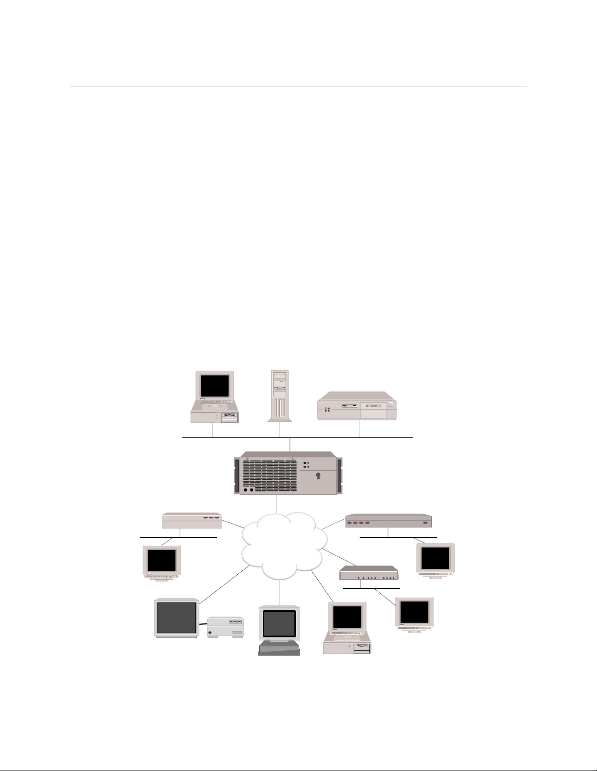
SWITCH
Remote ISDN Bridge
Workstation
Sun SPARCstation
Host
BRI
File Server
BRI
SW 56
Silicon Graphics INDY
ISDN
Router
Z
BRIs or
PRIs
BRI
INDY
with BRI ISDN TA
Remote ISDN Bridge
BRI
Workstation
Workstation
PC
Page 31

UNIQUE SYSTEM FEATURES
g
The CyberSWITCH combines unique features that improve cost-effectiveness, reliability, and
performance for wide area network connections to remote devices. These features include:
• Bandwidth Agility
The CyberSWITCH dynamically controls the bandwidth in use between itself and other PPP
devices. This is accomplis hed by establishing and disconnecting calls. The numb er of calls is
limited only by the types and number of lines available. The system monitors the connections
for utilization and will add and remove the connections based on user-configurable
through put p ar amet er s. As n etw ork band wid th r eq uir emen ts i ncr ea se or decre ase , the syst e m
will automatically adjust the number of networ k connectio ns. Thus, your netwo rk costs will
reflect the actual bandwidth being used.
• Filtering
The CyberSW ITC H’ s filte ring fea ture allow s you to contro l the flow of fram es thro ugh the
network. Filtering becomes necessary if you need to restrict remote access or control
widespread transmission of sporadic messages. Customer-defined filters ca n forward
messages based on addresses, protocol, or packet d ata.
THE C
YBER
SWITCH
Unique System Features
• Combining Leased Line and Switched Connections
Use the Switched Connections feature to automatically backup failed or overloaded leased
lines (for example, in peak hour overflow situations). The capability of combining switched
connections with leased line capacity allows you to reduce costs and greatly improve the
reliability and perfo rma nce of leased line netw orks .
The following graph illustrates the relationship between cost and hours of usage when
comparing a switched connection to a dedi cated connection:
Switched
Cost
Hours of Usa
Connection
Dedicated Connection
e
• Data Compressi on
The Cyber SWITCH can negot iate com press ion alg orithms with an other device on the network .
After successfully negotiating compre ssion, data is compressed by the remote device and
transmitte d to the CyberSWITCH system. The sys te m decompresse s the data, processes the
information contained in the user data, and forwards the data as required. The system can
receive data coming over a WAN or a LAN, and compress the data before transmitting it to
another device on the network. The net effect is to increase interconnect bandwidth by
decreasing transmission time. If negotiation for compression fails, data is transmitted
uncompressed.
Central Site Remote Access Switch 31
Page 32

USER’S GUIDE
• Data Encryption
The CyberSWITCH encry p tion option provides da ta e ncryption through th e Data Encryption
Standard (DES) algorithm. DES provides data security for transmissions over the WAN
between e ncryption devices. Options are available for encrypting communications over point-
to-point, frame relay, or Internet-based WANs. For more information, refer to the Encryption
Overview and IP Security discussions.
To activate the data encryption option on the CyberSWITCH, you will need to properly install
and configure the encryption adapter on the system.
• Dial Out Capability
The CyberSWITCH syste m w ill dia l out to rem ote de v ices . Thi s feat ure a llo ws the sys t em to
accept u ser data rec ei ved on t he Et he rnet LAN o r IS DN n etwo rk a nd i niti ate a d ata co nnec tion
to the remote device specified in the user data. This allows devices on the local LAN to initiate
connection s to netw o rk s co n n e ct e d to th e system over th e sw i tc h e d d ig ital ne tw ork. Th e
system monitors the connection for utilization and will remove the connection when it becomes
idle.
• Digital Modem
The CyberSWITCH’s dig ital mo d e m capa bilit y all ow s ana lo g mode m s to be inter mix ed with
ISDN, as required, to best fi t specific networking needs. The d i gital mo dem adapter combines
both hardware and so ftware el ements to s upport a number of modems on a sin gle boa rd (from
eight V.34 modems to t hirty K56Flex modems, depending upon adapter model). The digital
modem feature conform s to the V.90 standa rd.
• Dynamic Management
Manage Mode provides a “real-time” managemen t mechanism that allows many sys tem
paramet e rs to be changed wi thout inter ru p ting the current execution state of th e system
software. This featur e consists of a ser ies of console commands that enable a user to display
current system par a m et e rs , ch an g e ma n y p ar a m et e rs dyn a m ically, an d write changes to di s k
files so that they remain perm ane nt.
• High Speed Digital Connections
The CyberSWITCH system supports 56Kbps and 64Kbps connections to remote locations.
These dial-up digital connections provide reliable high throughput connections for efficient
data transfer for the same cost as analog connection s . If any remote devices connected to the
system support multi-link PPP, up to 32 parallel connections can be made at either 56Kbps or
64Kbps.
• IP Filters
IP filters allow you to control the transmission of individual IP packets based on the packet
type. You can specify packet type by IP address (source or destination) or by IP protocol (TCP,
UDP, ICMP).
Once you specify a packet type, two forms of IP filtering are available:
• Forwarding Filters, applied at discrete points of the IP processing path to determine if a
packet continues its normal processing, and a
• Connection Filter, which determines if an IP packet requiring a WAN connection may continue.
32 CyberSWITCH
Page 33

THE C
YBER
Unique System Features
•IP Security
The Cy b erS WITC H e ncrypti on option implem e n ts En c apsulating Se cu r i ty P a y load (ES P )
protocol. ESP allows you to use Cy b e rSWITCH nodes to implement a Secure Wide Area
Network usi ng the Intern e t as a b ackbone. ESP provides confidentiality of data transmissions
using encryption to assure that pack ets intercepted during transit through the in ter n et c an not
be interpreted.
The CyberSWITCH encryption option supports ESP Tunnel mode, in which an entire IP
datagram (includ ing its header) is encrypted and place d in a new IP datagram. This option
provides the flexibility to choose which IP addresses must be sent encrypted data, and which
may receive plain (unencrypted) data. The CyberSWITCH encryption option provides WAN
connectivity for up to 92 B channels (with PRI and/or BRI connections).
• Link Layer Encryption
The CyberSWITCH also provides the ability to do encryption at the PPP layer usin g Encryption
Contr ol Protocol with comp atible de vices.
• Multiple MAC/IP Addresses
This featu re allow s two or more nod es to back up each other th rough th e use of the Connecti on
Services Manager (CSM).
SWITCH
With this feature, two or more identically configured CyberSWITCH nodes on the same LAN
can be monitored by CSM. Should CSM notice some con di tion which precludes one of the
CyberSWITCH no des from proper ly p erfo rming its fun ctio n, it will orde r the other
CyberSWITCH node to take over the other’s duties by taking on its iden tity (i.e., its MAC an d
IP addresses).
•Packet Capture
In order to monitor incoming LAN data, the CyberSWITCH packet capture feature will allow
you to capture, display, save, and load bridged or routed data packets.
• Protocol Discrimination
It is possible for multiple types of remote devices to use the same line. The system can
determine the device type and the protocol encapsulation used by remote devices.
• RS232 Port: Dual Usage
If your installation requires you to process PPP-Async data, this feature allows you to use the
RS232 port for either console acc ess or a serial data connection. This dual usage is possible
through th e CyberSWITCH’s support of Autosense mode (th e system default) and Terminal
mode:
• Autosense mode determines whether you are trying to connect using a VT emulation or PPP-
Async, and connects you appropriately. (VT emulation requires you to perform four carriage returns to receive a login prompt.)
• Terminal mode assumes that you o nly wa nt to conne ct u sing VT e mulati on. A log in promp t
is displayed as soon as the connec tion is made.
•Security
Security is a key issue for all central site network mana gers and is a priority with the
CyberSWITCHs. The products provide high level features that help prevent unauthorized or
inadvertent access to critica l data and resources . They support extensive security levels
including:
• PPP PAP and CHAP
Central Site Remote Access Switch 33
Page 34

USER’S GUIDE
• User n a me a n d pa ssword
• Calling Line ID (CLID)
• Ethernet Address
• User Authentication
• Device Authentication
• Connectio n Services Manager (CSM)
• TACACS Client with Radius Server
•RADIUS
• Security Dynamic’s A CE/SecurID
• Server Support
The CyberSWITCH supports both Authentication and Accounting Servers. Authentication
Servers provide a central database for networks with more than one CyberSWITCH . Th e
central database consists of manag e ab le, info rmational data (referred to as the Device List or
Device Ta b l e ). T hi s da ta i s a cc e ss e d a nd use d for au the ntica tio n when a new connec t i on is
established to the system.
The CyberSWITCH also supports a RADIUS Accounting Serve r to maintain accounting
information, such as length of connec tion s. This capability should be especially useful to
Internet Service Providers.
• Simultaneous Connections
The CyberSW ITCH system supp orts simult a neo us connec t ion s to mult iple loc a tions . These
locations can connect by using different channels on the same line, or they can connect on
different lines. This pooling of lines among many potential locations is more cost effective than
alternative point-to-point lines.
INTEROPERABILITY OVERVIEW
“Interoperability” is the ability to operate and exchange information in a heterogeneous network.
The CyberSWITCH supports interoperability with many different remote devices over ISDN.
INTEROPERABILITY PROTOCOLS
In order to commun icate wi th vari ous remot e devic es over I SDN, the CyberSWI TCH must i dentif y
the device type and the protocol it is using.
The CyberSWITCH supports the following line protocols:
• HDLC Ethernet Frames
• Ordered Protocol for Ethernet Frames
• RFC1294 Based Encapsulation for IP Datagrams
• Point-to-Point Protocol (PPP) Encapsulation for IP Datagrams
The CyberSWITCH supports the following encr yption protocols:
• Encapsulating Security Payload Proto col (ESP)
• Encryption Co ntro l Protoc ol (EC P)
The CyberSWITCH supports the following PPP protocols:
• Link Control Protocol ( LCP)
• Multilink Protocol (MLP)
34 CyberSWITCH
Page 35

• Authentication Protocols
Challenge Handshake Authen tication Protocol (CHAP)
Password Authentication Protocol (PAP)
• Network Con trol Protocols (NCP)
Interne t P rotocol Control Protocol for TCP/IP (IPCP)
Intern e t work Packet Exchange Co ntrol Protocol for IPX (I PXCP)
Bridge Control Pro toc ol for bridg es (BCP)
• Compressi on Control Pr otocol (CCP)
• AppleTalk Control Protocol (ATCP)
The CyberSWITCH supports the fo llowing AppleTalk protocols:
• EtherTalk Link Access Protocol (ELAP)
• AppleTalk Address Resoluti on Protocol (AARP)
• PPP AppleTalk/AppleTalk Control Protocol (ATCP)
• Datagram Delivery Protoco l (DDP )
• Routing Tab le Maintenance P rotocol (RTMP)
• AppleTalk Echo Protocol (AEP)
• Name Binding Protocol (NBP)
• Zone Inform ation Protocol (ZIP)
THE C
YBER
SWITCH
Interoperability Overview
INTEROPERABILITY DEVICES
Remote devi ces that may connect to the Cybe rSWITCH include the following:
• MAC Lay er Bridges
•IP Host Devices
• IP Router Dev ices
• IPX Route rs
• AppleTalk Routers
MAC layer bridge s connec t to the syste m using the HD LC bridge encap sula tion line p rotoc ol .
These devi ces send transpar ently bridged E therne t frames to the sy stem. MAC layer br idges do not
process ne twork layer protocols. The y forward all packets based on source and destinati on MAC
addresses.
IP Host devices are single workstations or PCs that co nne ct to the system at the IP network layer.
These devices use either the RFC1294 based protocol or PPP to communicate with the system.
IP router devices are single devices that represent many ot her IP hosts and ro uters to the syste m.
They must use the CHAP or PAP protocol to identif y themselves to the system. IP routers usually
provide IP network address information at connection time (and use PPP to send user data to the
system).
IPX routers are single devices that perform network layer tasks (addressing, routing, and
switchin g) to move packet s from one location on the network to another. IPX routers use the
Internetwork Packet Exchange (IPX) protocol, typical of the NetWare environment.
AppleTalk routers route AppleTalk datagrams based on address information. They support the
following protocols: RTMP, NBP, and ZIP.
Central Site Remote Access Switch 35
Page 36

USER’S GUIDE
ENCRYPTION OVERVIEW
Cabletron’s encryption options provide two popular approaches for encrypting WAN
communica tions, each with di stinct advantag es i n certai n appli cations . The se opti ons are: Netwo rk
Layer Encryption and Link Layer Encryption.
NETWORK LAYER
Cabletron’s Network Layer Encryption is an IP Security-based form of encryption. IP Security
(IPSec) can potentially reside in many devices within the network. Since IPSec is specific to IP, data
must be cont ained in an IP d ata gram in o rder for en crypt ion to take pla ce. Th is also imp lies that an
IPSec-compliant switch or router must perform network-layer routing. A device which does not
perform network-layer proce ssing (such as a pure bridge) will not be capable of IPSec-ba s ed
encryption. Non-IP protocols su ch as IPX and AppleTalk mu st be encapsulated within IP in order
to take advantage of IPSec.
IPSec is primarily aimed at providing secure communications across IP networks such as the
Interne t . Data can trave rse multiple intermediate (untrusted) nodes (such as Internet backbone
routers) while still ensuring strong data security. But it can also be applied in point-to-point
networks where the layer-3 protocol is IP (for example, IP transported across the WAN using PPP).
Network-layer encryption works as follows:
IP datagrams transmitte d from one LAN to another LAN funnel through a CyberSWITCH node
where they are encrypted and encapsulated. The destination address on the encapsulated
datagram is that of the C yberSWITCH node servicing the other trusted subnet.
When the IP datagram reache s the destination CyberSWITCH node, the Encapsulating Security
Payload (ESP) header is remo ve d, the ESP payload is decrypted , an d th e original IP datagram is
forwarded to its original des tin atio n.
CyberSWI TCH encry ption requir es a dditional Security Associati on information that can be supplied
through CFGEDIT. Each security association identifies a range of IP addresses, encryption
parameters to be used to encrypt communications to those IP addresses, and the IP address of the
peer CyberSWITCH (or other ESP node) responsible for decrypting the communications. The peer
will have knowledge of the same security association.
Security associations between peer CyberSWITCH nodes are identified by a Sec urity Parameter
Index (SPI), which is a 32-bit number. The SPI is transmitted in the ESP header and is used by the
peer CyberSWITCH node to identify the necessary information to decrypt the E SP payload.
IP datagrams to these IP destination addresses are encrypted and encapsulated with an ESP header.
The ESP header indicates a destination address of an intermediate CyberSWITCH node which will
be responsible for decrypting and decapsulating these packets before sending them on to their
intended destination.
LINK LAYER
Link layer encryption occurs at layer 2 of the ISO networking model. In the case of a WAN, PPP
acts as a lay e r 2 p rotocol. Encryption C ontrol Protocol (ECP) serves to handle encryption of a PPP
datagram.
36 CyberSWITCH
Page 37

Link layer encryption is in dependent of any network layer protocols . Sin ce PPP provides t ransport
of IP, IPX, AppleTalk, and other protocols, link layer encryption based on ECP provides multiprotocol e ncrypti on by def ault. Dev ices im plementin g it can act as router s or brid ges, as l ong as the
underlying WAN protocol is PPP.
To use link layer encryption, the co nnection between encrypting and decrypting devices must truly
be point-to-point. This includes ISD N dial-up connec tions, or point-to-point dedicated lin e s.
SECURITY OVERVIEW
The system provides several options for validating remote devices and for managing network
security. The security options available are dependen t on the remote device type, type of access ,
and the level of security required.
Levels of security include no security, device level security, user level security, and multi-level
security. Device level security is an authentication process between devices, based on protocol and
preconfigured information. Sec urity information is configured either in the system’s On-node
Device Dat abase, or in a ce ntral database such CSM. Here the network administrato r sp e cifies all
of the security information for each individual user. A portion of this information is used to identify
the remote device. The remain ing data is used to perfor m user valida tio n after user iden tifica tion
has been completed.
THE C
YBER
SWITCH
Security Overview
User level security is an interactive process. It is currently supported on the system through the
TACACS or ACE server programmed for use with security to ken cards. With user leve l security,
the potential network user explicitly connects to the server and must properly “converse” with it
in orde r to co n ne c t with othe r devic e s b ey o n d the serv er .
Import ant to user level authentication is th e se curity token card. Th is card, programmed in
conjun ction with the authentication server, gene rates random passwords. These passwords must
be supplied correctly at syst em login tim e, or acces s to the networ k will be den ied. The secur ity
token cards should be issu e d to each user on the network to properly maintain system inte grity.
Multi-level security provides device level security for all remote devices. Individual devices may
be configu red for user level authentication as well. In this case , device l e ve l authentication takes
place between the system and the remote device. Then a specific user must initiate user level
authentication by sta rting a Telnet session. Both levels of authentication must b e satisfied before
traff ic can pass.
NETWORK INTERFACE OVERVIEW
The network interface is the physical connection of the CyberSWITCH to a data network. For
example, the Ethernet resource in the system provides a net work interface to an Ethernet LAN. The
ISDN lines in th e s yste m prov i de netw ork i nter fac es t o mu ltip le r emote net wor ks. Beca use of th eir
switched nature, the ISDN lines provide virtual network interfaces. That is, the same physical ISDN
line can actually c onnect to different remote networks by d ialing a different phone number.
The CyberSWITCH provides a set of network interfaces that give you a wide range of flexibility.
The network interfaces provided by the system are:
• LAN IP Network Interface
• LAN IPX Network Interface
Central Site Remote Access Switch 37
Page 38
USER’S GUIDE
• WAN IP Network Inte rface
• WAN (Direct Host) IP Network Interface
• WAN RLAN IP N etwork Interface
• WAN RLAN IPX Network Interface
• WAN (UnNumbered) Network Interface
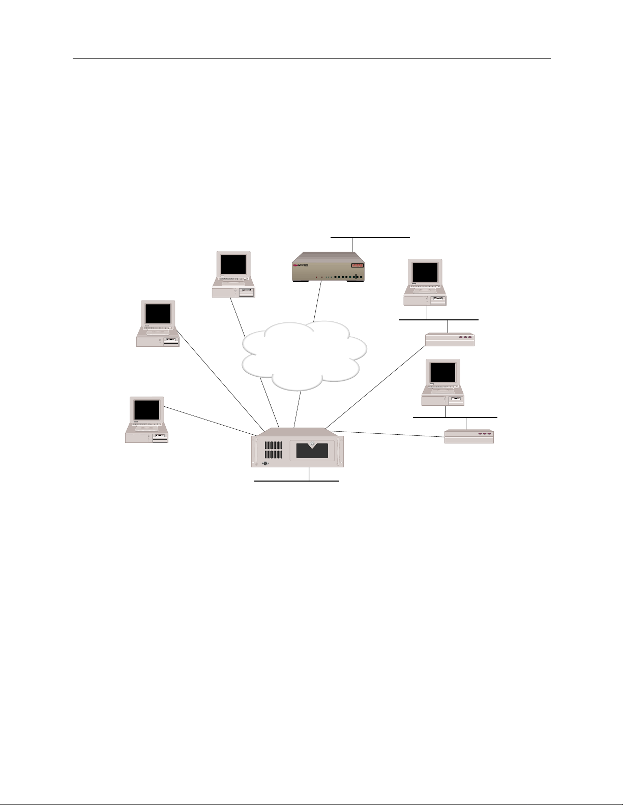
The variety of ne twork interfaces allows the install a tion of a wide ra nge of devices at re mote sites.
As illustrated below, you can simultaneously choose bridges, routers, or host devices based on the
speci f ic re mote site requ i r e ments.
128.1.1.3
Host
192.1.1.2
Host
(or Router)
CyberSWITCH
WORKGROUP REMOTE ACCESS SWITCH
POWER
LAN
B1 B3
10BASE-TRXTXSERVICE
B2 B4
192.1.1.3
B13B15
B9B11
B5 B7
E1DT1
B14B16
B10B12
B6 B8
206.32.11.0
206.32.11.1
E1 ONLYB-CHANNELS
B25B27
B29
B31
B21B23
B17B19
D
B26B28
B30L1
B22B24
B18B20
100.1.1.2
Remote
Bridge
ISDN
100.1.1.3
128.1.1.2
Host
WAN
Interface
192.1.1.1
WAN Direct Host
Interface
RLAN
100.1.1.1
Remote
Bridge
CSX5500
LAN Interface 128.1.1.1
In the diagram above, t he LAN Interface 128.1. 1.1 is attach ed to the IP network 128. 1.0.0. The WAN
Direct Host Int erface represent s LAN Interface 128. 1.1.1 and all ows the remote IP h osts to share the
network address space of 128.1.0.0. The WAN Interface 192.1.1.1 is logically attached to the IP
network 192.1.1.0. The RLAN Interface 100.1.1.1 is logically attached to the IP network 100.1.1.0.
SYSTEM COMPONENTS
The majo r co m p o ne nt s of th e CyberSWI TCH are:
• System hardware consisting of a platform, an administration port provided by the platform,
and adapters.
• System software spec ific to the CyberSWITCH, adapter modules, and administration
function s.
• Administration software that provides configuration, diagnostics and maintenance on the
system.
• System files containing configuration and operational information.
• Remote I S DN devices wh ich inter op e rate with the system and allo w device access to n e twork
resources.
38 CyberSWITCH
Page 39

More deta iled desc ripti ons of sy stem so ftware an d hardwar e are included in the nex t two chap ters .
The following section describes remote ISDN devices.
REMOTE ISDN DEVICES
The CyberSWITCH provides a centralized concentrator function for remote ISDN devices. The
devices can be separated into the following categories:
• remote ISDN bridge devices
• PC based terminal adapters
• ISDN enabled workstations
• other ISDN routers
Typical remote ISDN bridges provide one Ethernet port and one basic rate ISDN port. The basic
rate port is connected to the switched digital network and is used to make connections to the
CyberSWITCH. The Ethernet port is used to connect to a remote LAN. The remote bridge device
sends Ethernet frame s from device s on the remote LA N over the switched network .
PC-based terminal adapte rs connect to a remote personal compute r an d us e the switche d d igital
network to con nect to the system. The termina l ad ap te r sends network protocol specific frames
from the host PC device over the switched network.
THE C
YBER
SWITCH
Remote ISDN Devices
Workstat ion-based terminal adapter s connect to a work station and use the switched digi tal
network to con nect to the system. The termina l ad ap te r sends network protocol specific frames
from the wor kstation over the switched network.
Central Site Remote Access Switch 39
Page 40

USER’S GUIDE
SWITCHES SUPPORTED
Switch types supported by the CyberSWITCH’s basic rate and primary rate ISDN adapters:
Type of Switch Basic Rate Primary Rate
AT&T #4ESS NA Yes
AT&T #5ESS Yes Yes
AT&T Definity Yes Yes
AT&T Legend Yes NA
NET3 Yes NA
NET5 NA Yes
NT DMS 100 Yes Yes
NT DMS 250 NA Yes
NT DMS 500 NA Yes
NT SL-100 Yes Yes
NTT Yes Yes
NI-1 Yes NA
TS013 Yes NA
TS014 NA Yes
1TR6 Yes Yes
Switch support may vary from country to country. Use the following as a guideline:
Country Switches supported
(BRI lines)
Australia TS013
NET3
Germany 1TR6
NET3
Japan NTT NTT
United States AT&T 5ESS
AT&T Definity
AT&T Legend
NT DMS 100
NI-1
Switches supported
(PRI lines)
TS014
NET5
1TR6
NET5
AT&T 4ESS
AT&T 5ESS
AT&T Definity
NT DMS 100
NT DMS 250
NT DMS 500
NT SL-100
40 CyberSWITCH
International NET3 NET5
Page 41

H
ARDWARE OVERVIEW
The product you have purchased is integrated on the following platforms: the CSX5500, CSX6000,
and CSX7000. Through the use of adapters, these platforms support remote routing and bridging
of local area netw orks using ISDN BRI or PRI services. Options also i nclude V.35, RS232, encryption
adapters, and Digit al Modem connections.
This chapt er pro vides a descri ption of system p latfor ms and adapters . We al so includ e desc riptio ns
of sever al products th at we support that were produced by Network Express.
SYSTEM PLATFORMS
The CyberSWITCH consists of a main proce ssor and system memory. The type of p rocessor and
the number of available slots vary by model. (See table.) The front of the platform has a diskette
drive, control buttons, LED indicators and an LCD display. Connect ors for the power, the LAN,
and the network ar e all loc ated o n the bac k of the chassi s. Ad ministr ation po rts fo r local and re mote
administration console attachments are also located on the back of th e chassis.
Platform Number of
Slots
Main
Processor
Speed
CSX5500 6 Pentium 133 MHz
CSX6000 8 Pentium 90 MHz
CSX7000 16 Pentium 133 MHz
NE 2000-II 3 i486 25 MHz
NE 4000 6 i486 33 MHz
NE 5000 8 i486 66 MHz
Page 42

USER’S GUIDE
THE CSX5500
Air Intake
Keyboard Connector
Grill
(auxillary)
5500
TM
Door
Latch & Lock
Rack
Mounting
Plates
PLATFORM DESCRIPTION
The CSX5500 is a high c apacity, central site communications platform. This platform is a LAN/
WAN bridge /route r b uil t t o acco mmod ate mul tip le WAN t ech nol ogi es. It supp orts up to 16 ISDN
BRI ports or 4 PRI ports, 2 di gital mo dem card s, V.35, Fr ame Rel ay and Dedicated Lines servi ces. It
supports TCP/IP, IPX, and AppleTalk, as well as ML-PPP and compression. It has single or dual
port Ethernet capability. The CSX5500 utilizes a CPU with 133 MHz Pentium processing.
5500
TM
Power & Activity
Indicators
HDD POWER
Power
On/Off
TM
Air Filter
RESET
Reset Button
Diskette Drive
Activity
Indicator
3.5" Diskette Drive
Diskette
Release
42 CyberSWITCH
Page 43

H
y
ARDWARE OVERVIEW
System Platforms
The CSX5500 is a rack-mountable platform. The front panel has an air-intake grill, an auxiliary
keyboard jack, and a peripheral access door, which may be latched. The activity indicators for
power-o n and disk activity, diske t te drive, and control bu ttons are located behind the access door.
The back of th e chassis has mountings for a RS- 232 serial port, and connectors for a k e yboard and
monitor. The chassis has eight ISA slots for LAN and WA N adapters. However, because of power
and cooling restr ictions , we limit the number of usable ad apter sl ots to fiv e (one for a LAN adapter ,
and up to four for WAN adapters).
Exhaust
Fans
Power
Supply
Fan
Line Voltage
Selector
Switch
115
Video
Connector
Com1
Connector
Keyboard
Connector
AC Power
In/Out
C
LEANING THE CSX5500 A IR FILTER
The CSX5500 has a removable air filter. This filter is provided to ensure system cleanliness and
stability in dusty operating environments. The filter is located just behind the left side of the
chassis ’ front pa nel. F or best performa nce (and as an al ternati ve to rep lacemen t) regul arly wa sh the
filter in warm water and a mild detergent.
Before removing the air filter for cleaning, read the following warning and caution notes.
WARNING
Before removing th e air filter f or cl eaning, ens ure that t he sy stem is po wered off and the po wer
cord is unplugged from the power source. Note th at the Power ON/OF F switch does not
disconnect the power fr om the system. Failure to unplug the power cord can result in serious
injury or equipment damage.
CAUTION
An electrostatic discharge (ESD) can damage your system. We recommend that you perform
this procedure only at an ESD workstat ion . If such a workstation is unavailable, pr ovide some
ESD protection by wearing an antistatic wrist strap attached to chassis ground when handling
components.
Auxillary
Ke
board
PCI slots for
Future Use
For
CPUs
ISA slots for LAN & WAN
Adapters
Central Site Remote Access Switch 43
Page 44

USER’S GUIDE
To clean the air filter:
1. Power down the system and disconnect the system ’s p ower cord from the power sou rce.
2. Open the do or located on the right side of t he front chassis.
3. Once the door is opened, you can slide the air f ilter out from the left side of the chass is.
4. Once removed, clean the filter by washing it in warm water and a mild detergent. Make sure it
is completely dry before you place it back in the system.
5. Slide the filter back into place.
6. Close the ch assis door.
7. Reconnect the power cord and power up the system.
P
LATFORM CHARACTERISTICS
Physical Char acteristics
Height: 171.5 mm (6.86 in)
Width: 430 mm (17.2 in)
Depth: 483 mm (19.32 in)
Weight: 18 kg maximum (40 lb . maximum )
Environmental Characteristi cs
Operating Temp: 0° to 55° C (32° to 131° F)
Operating Humidity: 5 to 95% non- condensing
Operating Altitude: 3048 m maximum (10,000 ft maximum)
Non-operating Shock: 40 G, 11 ms 1/2 sine wave
Storage Temperature: 0° to 70° C (32° to 158° F)
Electrical AC Power Input
Voltage: 90 - 120 V Current:5 A
Voltage: 180 - 265 V Current:4 A
Frequency: 47 - 63 Hz
Regulatory Compliance
Meets or exceeds the following:
Safety: UL 1950, CSA C22.2 No. 950, EN 60950, IEC 950,
EMI: FCC Part 15, EN 55022, CSA 108.8, EN 50082-1,
Rack Mounting:
475 mm (19 inch) Industrial Rack Mount C hassis meets EIA RS-310C standard
and 72/23/EEC
VCCI V-3, and 89/336/EEC
44 CyberSWITCH
Page 45

CAUTION FOR DC-POWERED CSX5500S
H
ARDWARE OVERVIEW
System Platforms
!
CAUTION
• Conn ec t to a reliably-g ro u nd e d SE LV so u r ce .
• Use branch circuit overcurrent protection rated at 15A only.
• Use 12 or 14 AWG conductors only.
• Incorporate a readily-accessible disconnect device in the field wiring that is suitably ap-
• Install in a restr icted acce ss area in accordance with the NEC or the authority having juris-
To reduce the risk of electrical shock or energy hazards:
proved and rated.
diction.
Central Site Remote Access Switch 45
Page 46

USER’S GUIDE
THE CSX6000
Z
Slot 1
PLATFORM DESCRIPTION
The CSX6000 is a high density, modular, central-site communications platform. It utilizes a built in
CPU with 90 MHz Pentium p rocessing.
The CSX6000 is a rack-mountable platform. The front panel has the act ivity indicators for poweron and disk activity, an air-intake grill, and a peripheral access door, which may be latched or
locked clo sed. The diske tte drive, control butto ns, and an LCD di splay are loca ted behind the acc ess
door. On the back of the chassis, the rear panel has mountings for a RS-232 serial port, and
connectors for a keyboard and monitor.
The CPU is located in the center of the chassis in the one ISA + PCI slot (labe lle d slot 1 in the back
panel illustration). There are nine additional ISA sl ots for adapter s to the right of the CPU board.
However, be cause of pow er and cool in g r est rict i ons, w e li mit t he n umbe r o f u s able adapt e r sl ot s to
seven (one for a LAN adapter, and up to six for WAN adapters).
Power Input
Socket
A
M
P
Circuit
Breakers
A
M
P
Keyboard
Connector
46 CyberSWITCH
Page 47

CLEANING THE CS X6000 AIR FILTER
The CSX6000 has a removable air filter. This filter is provided to ensure system cleanliness and
stability in dusty operating environments. The filter is located just behind the chassis’ front panel.
For best performance (and as an alternative to replacement) regularly wash the filter in warm water
and a mild detergent.
Before removing the air filter for cleaning, read the following warning and caution notes.
WARNING
Before removing th e air filter f or cl eaning, ens ure that t he sy stem is po wered off and the po wer
cord is unplugged from the power source. Note th at the Power ON/OF F switch does not
disconnect the power fr om the system. Failure to unplug the power cord can result in serious
injury or equipment damage.
CAUTION
An electrostatic discharge (ESD) can damage your system. We recommend that you perform
this procedure only at an ESD workstat ion . If such a workstation is unavailable, pr ovide some
ESD protection by wearing an antistatic wrist strap attached to chassis ground when handling
components.
H
ARDWARE OVERVIEW
System Platforms
To clean the air filter:
1. Power down the system and disconnect the s y stem’s power cord from the power source.
2. Tur n the f ou r q u a rt er - turn scre w s se cu r i ng th e fr o nt panel to th e c ha s si s .
3. Remove the front panel to access the fan filter.
4. Remove the f an filter.
5. Once removed, clean the filter by washing it in warm water and a mild detergent. Make sure it
is completely dry before you place it back in the system.
6. Reposition the filter and the front pane l.
7. Tighten the four front pane l quarter-turn screws.
8. Reconnect the power cord and power up the system.
P
LATFORM CHARACTERISTICS
Physical Char acteristics
Height: 178 mm (7.0 in)
Width: 482.6 mm (19.0 in)
Depth: 558.8 mm (22 in)
Weight: 18 kg maximum (40 lb. maximum)
Central Site Remote Access Switch 47
Page 48

USER’S GUIDE
Environmental Characteristi cs
Operating Temp: 0° to 55° C (32° to 131° F)
Operating Humidity: 5 to 95% non- condensing
Operating Altitude: 3048 m maximum (10,000 ft maximum)
Non-operating Shock: 40 G, 11 ms 1/2 sine wave
Storage Temperature: 0° to 70° C (32° to 158° F)
Electrical AC Power Input
Voltage: 90 - 120 V Current:5 A
Voltage: 180 - 265 V Current:4 A
Frequency: 47 - 63 Hz
Regulatory Compliance
Meets or exceeds the following:
Safety: UL 1950, CSA C22.2 No. 950, EN 60950, IEC 950,
EMI: FCC Part 15, EN 55022, CSA 108.8, EN 50082-1,
C
AUTION FOR DC-POWERED CSX6000S
and 72/23/EEC
VCCI V-3, and 89/336/EEC
!
CAUTION
• Conn ec t to a reliably-g ro u nd e d SE LV so u r ce .
• Use branch circuit overcurrent protection rated at 15A only.
• Use 12 or 14 AWG conductors only.
• Incorporate a readily-accessible disconnect device in the field wiring that is suitably ap-
• Install in a restr icted acce ss area in accordance with the NEC or the authority having juris-
To reduce the risk of electrical shock or energy hazards:
proved and rated.
diction.
48 CyberSWITCH
Page 49

THE CSX7000
7000
BC GROUP
MULTIPORT BOARD
MP SERIAL PORT
BC RESET
PWR SUPPLY 1
PWR SUPPLY 2
DATA HIGHWAY
SUBSYSTEM FAULT
ENVIROMENTAL ALLERT
AUDIBLE CLEAR
UNLOCK
SUBSYSTEM DATA
FANS
LOCK
CONSOLE
GROUP PWR
TRANSMIT
RECIEVE
CARRIER
RING
LAN ATTATCHED
DISK ACTIVITY
VIDEO SELECT
H
ARDWARE OVERVIEW
System Platforms
ON OFF
MP BC
DTR
DSR
RTS
CTS
ENABLED
DISABLED
PLATFORM DESCRIPTION
The CSX7000 is designe d for larg e, central sites and Intern et Service Providers. It is a high
availability, remote access switch that offers modularity and flexibility for these large sites.
The CSX7000 co nsists of a platform, processor modules, and an Environmental Management System
Module, and includes environmental management of one or more platforms. It is ca pable of
containing multiple process or modules (for backup or additio nal line capacity) in the platform’s 16slot backplane. The CSX7000 may also support other servers, including authentication servers.
Currently, a single CSX7000 platform supports a maximum of four proc essor modules (or system
groups) at a t ime. Each sys tem grou p suppo rts a max imum of one Pr ocessor Module card , one LAN,
and six WAN cards. ( Of course, four fully-maxi mized system groups would not fit into the 16-sl ot
backplane). Up to 31 CSX7000 platforms may be daisy-chained together to form a cluster.
Because of its unique platform feat ures, the CSX 7 000 is descr ibe d in furt her det ail in the CSX7000
Guide.
P
LATFORM CHARACTERISTICS
Environmental Characteristi cs
Operating Temperatu re: 0° to 45° C (32° to 113° F)
Storage Temperature: -20°+70°C
Operating Humidity: 20 -85% non-condensing
Operating Altitude: Up to 3048 m max (10,000 ft max.)
Non-operating Shock: 40 G, 11 ms
Central Site Remote Access Switch 49
Page 50

USER’S GUIDE
Physical Char acteristics
Power Supply Specifications
Regulatory Compliance
Disk Drives
Height: 218 mm (8.60 in)
Width: 483 mm (19.0 in)
Depth: 641 mm (25.25 in)
Weight: 36 kg max. (80 lb. max.)
350 Watt power supply; two versions with different input AC voltages:
• Version 1
AC Input Voltage: 90 to 135 V
AC Input Current: 7.5 A
AC Input Frequency: 47 - 63 Hz
• Version 2
AC Input Voltage: 180 to 264 V
AC Input Current: 4.0 A
AC Input Frequency: 47 to 63 Hz
Meets or exceeds the following:
Safety: UL 1950, CSA C22.2 No. 950, EN 60950, IEC 950,
and 72/23/EEC
EMI: FCC Part 15, EN 55022, CSA 108.8, EN 50082-1,
VCCI V-3, and 89/336/EEC
Number of 1/3 height,
IDE disk drives supported: 8
C
AUTION FOR DC-POWERED CSX7000S
!
CAUTION
• Conn ec t to a reliably-g ro u nd e d SE LV so u r ce .
• Use branch circuit overcurrent protection rated at 15A only.
• Use 12 or 14 AWG conductors only.
• Incorporate a readily-accessible disconnect device in the field wiring that is suitably ap-
• Install in a restr icted acce ss area in accordance with the NEC or the authority having juris-
To reduce the risk of electrical shock or energy hazards:
proved and rated.
diction.
50 CyberSWITCH
Page 51

THE NE 2000-II (A NETWORK EXPRESS PLATFORM)
H
ARDWARE OVERVIEW
System Platforms
Front View
Back View
Network
Express
Power & Activity
Indicators
3.5" Diskette Drive LCD Display
Activity
Indicator
Diskette
Release
Ethernet-2
Adapters
Power
On/Off
Board Slots
1-3
Line Voltage
Selector
Switch
PLATFORM DESCRIPTION
The NE 2000-II platform has t hree slots for adapters. This plat form is small enough in size to be
suitabl e for an office en vironment or to fit into a commu nication s rack. The front has a diskette
drive, control buttons and an LCD display. The display presents continuous status and error
information.
Connectors for the power, the LAN, and the network are all located on the back of the chassis. An
administrati ve port (shown as t he Remote RS232 Port o n th e fi gure), an d por ts for an optio nal loc al
monitor and keyboard are also located on th e b a ck of the chassis.
A/C Power
In/Out
AUXILARY
POWER
100-120V 2A 50/60HZ
200-240V 1A 50/60HZ
AC POWER
INLET
100-120V 2A 50/60HZ
200-240V 1A 50/60HZ
WARNING
Keyboard
Connector
10101
10101
COM 2
COM 1
Remote
RS232 Ports
BRI-4
Adapters
LPT
3
LAN
2
AUX
1
WAN
VIDEO
15 Pin
Monitor Port
Central Site Remote Access Switch 51
Page 52

USER’S GUIDE
PLATFORM CHARACTERISTICS
Physical Char acteristics
Height: 107 mm (4.2 in)
Width: 437 mm (17.2 in)
Depth: 411 mm (16.2 in)
Weight: 9 kg (20 lb)
Environmental Characteristi cs
Operating Temp: 10° to 35° C (50° to 95° F)
Operating Humidity: 20 - 80% non-condensing
Operating Altitude: 3, 048 m maximum (10,000 ft maximum)
Non-operating Shock: 30 G, 11 ms, 1/2 sinewave
Storage Temperature: 40°o to 70°o C (-40° to 158° F)
Electrical AC Power Input
Voltage: 90 - 132 V Current:5 A
Voltage: 180 - 264 V Current:3 A
Frequency: 47 - 63 Hz
Regulatory Compliance
Meets or exceeds the following:
Safety: UL 1950, CSA C22.2 No. 950, EN 60950, IEC 950,
EMI: FCC Part 15, EN 55022, CSA 108.8, EN 50082-1,
and 72/23/EEC
VCCI V-3, and 89/336/EEC
52 CyberSWITCH
Page 53

THE NE 4000 (A NETWORK EXPRESS PLATFORM)
H
ARDWARE OVERVIEW
System Platforms
Front View
Front Panel
Lock
Back View
Network
Express
WARNING
Power
Indicator
Hard Disk
Access
Indicator
Remote
RS232 Port
Reset
Power
On/Off
BRI-4
Adapters
LCD Diagnostic
Display
Ethernet-1
Adapter
3.5" Diskette
Drive
PLATFORM DESCRIPTION
The NE 4000 platform has six slots for adapters. You can place the platform either on its feet or
standing on a s ide . The f ron t has a d isket te d rive, con trol butto ns an d an LCD d ispl ay. The displ ay
presents conti nuous sta tus and e rror i nformati on. Conn ector s for the p ower, the LAN, T 1 inter face,
BRI, mouse , k eyboard and monitor are all located on the back of the chassis.
P
LATFORM CHARACTERISTICS
Physical Char acteristics
Height: 158 mm (6.22 in)
Width: 439 mm (17.3 in)
Depth: 434 mm (17.08 in)
Weight: 17.23 kg (38 lb)
A/C Power
In/Out
Keyboard
Connector
Video
Connector
1 2 3 4 5 6
Board Slots
1-6
Central Site Remote Access Switch 53
Page 54

USER’S GUIDE
Environmental Characteristi cs
Electrical AC Power Input
Regulatory Compliance
Operating Temp: 10° to 35° C (50° to 95° F)
Operating Humidity: 80% non-con densing
Operating Altitude: 3, 048 m maximum (10,000 ft maximum)
Non-operating Shock: 30 G, 11 ms, 1/2 sinewave
Storage Temperature: -40° to 65° C (-40° to 149° F)
Voltage: 100 - 120 V Current: 8 A
Voltage: 200 - 240 V Current: 5 A
Frequency: 47 - 63 Hz
Meets or exceeds the following:
Meets or exceeds the following:
Safety: UL 1950, CSA C22.2 No. 950, EN 60950, IEC 950,
and 72/23/EEC
EMI: FCC Part 15, EN 55022, CSA 108.8, EN 50082-1,
VCCI V-3, and 89/336/EEC
54 CyberSWITCH
Page 55
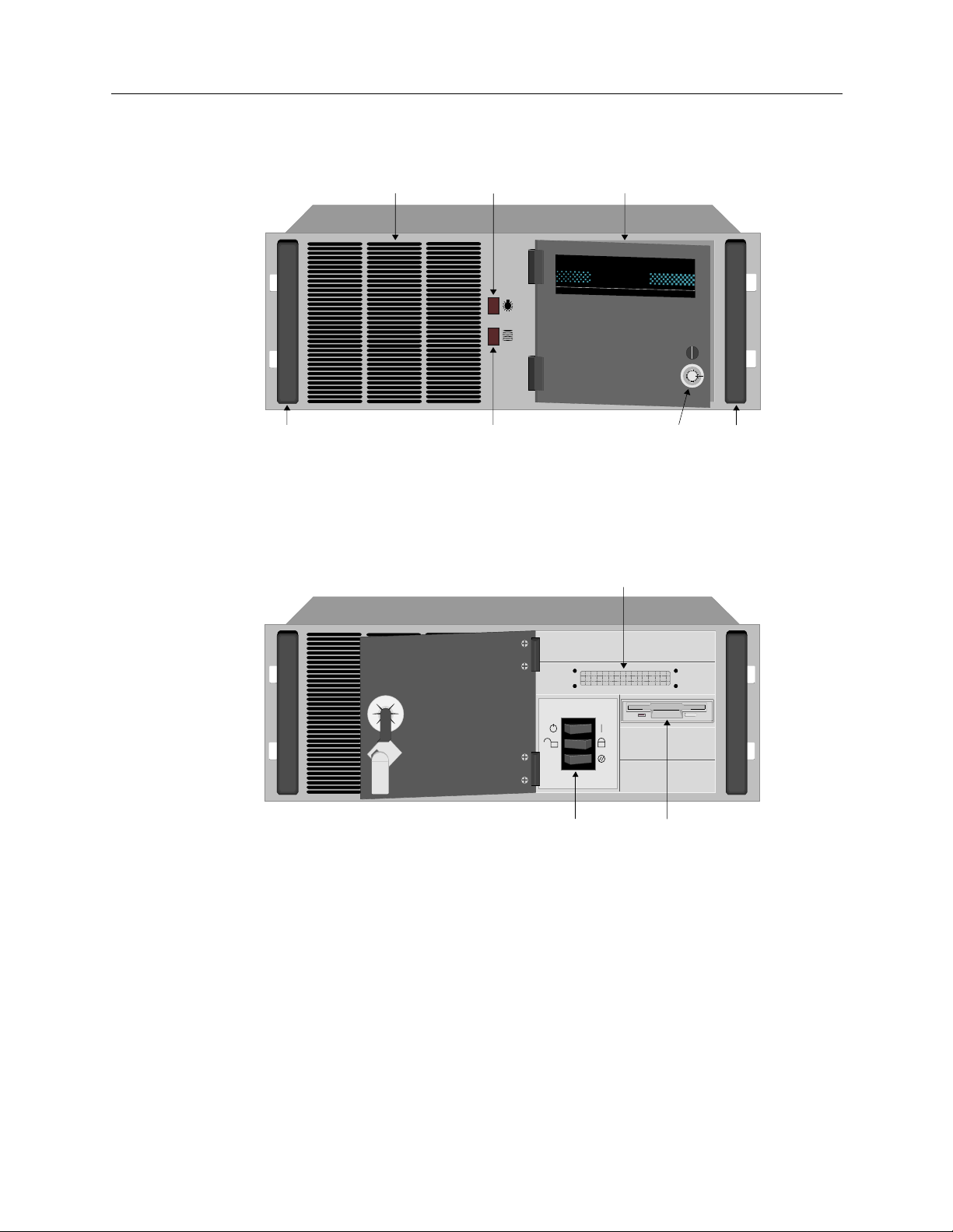
THE NE 5000 PLATFORM (A NETWORK EXPRESS PLATFORM)
Grill
Light Door
Network
Express
NE 5000
H
ARDWARE OVERVIEW
System Platforms
Front Panel
Door Open
Chassis
Handle
Disk
Light
LCD
Display
Power
Keyboard Lock
Reset
Door
Latch & Lock
3.5" Diskette
Drive
Chassis
Handle
PLATFORM DESCRIPTION
The NE 5000 is a rac k-mountable pl atfor m which pr ovides eig ht slo ts fo r adapte rs. The fr ont panel
has the activity indicators for power-on and disk activity, an air-intake grill, and a peripheral access
door, which may b e latched or loc ked close d. Behind the door is loca te d the diskette drive, control
buttons, and a n LCD display . On th e back of th e chassi s, th e rear pa nel has mounting s for a RS- 232
serial port, and connectors for a keyboard and a monitor.
Central Site Remote Access Switch 55
Page 56

USER’S GUIDE
Back Panel
A/C Power
In/Out
CLEANING THE NE 5000 AIR FILTER
The NE 5000 has a removable air filter. This filter is provided to ensure system cleanliness an d
stability in dusty operating environments. The filter is located just behind the chassis’ front panel.
For best performance (and as an alternative to replacement) regularly wash the filter in warm water
and a mild detergent.
Before removing the air filter for cleaning, read the following warning and caution notes.
RS-232 Port
Keyboard
Connector
Remote
VGA
Port
1 2 3 4 5 6 7 8
BRI-4
Adapter
Slots for
Adapters
Ethernet-2
Adapters
WARNING
Before removing th e air filter f or cl eaning, ens ure that t he sy stem is po wered off and the po wer
cord is unplugged from the power source. Note th at the Power ON/OF F switch does not
disconnect the power fr om the system. Failure to unplug the power cord can result in serious
injury or equipment damage.
CAUTION
An electrostatic discharge (ESD) can damage your system. We recommend that you perform
this procedure only at an ESD workstat ion . If such a workstation is unavailable, pr ovide some
ESD protection by wearing an antistatic wrist strap attached to chassis ground when handling
components.
To clean the air filter:
1. Power-down the system and disconnect the system’s power cord from the power source.
2. Remove the sy stem’s top cover.
3. Remove the tw o re taining screws holding the air filter in place.
4. Tilt the filter toward the rear of the chassis and lift the filter up and out of its position.
5. Once removed, you can clean the filter by washing it in warm water and a mild detergent.
Make sure it is completely dry before you place it back in the system .
56 CyberSWITCH
Page 57

6. Insert t he clea n and dry air fil ter bac k into i ts slo t behin d the chas sis fr ont. T ilt the f ilter f orward
into place unti l it is flush against the chassis fr ont panel.
7. Reinstall the two retaining screws along the top lip of the chassis.
8. Replace the sy ste m’s top cover.
9. Reconnect the power cord and power up the system.
P
LATFORM CHARACTERISTICS
Physical Char acteristics
Height: 178 mm (7.0 in)
Width: 432 mm (17.0 in)
Depth: 452 mm (17.8 in)
Weight: 22 kg maximum (44 lb. maximum)
Environmental Characteristi cs
Operating Temp: 0° to 50° C (41° to 122° F)
Operating Humidity: 20 - 85% non-condensing
Operating Altitude: 3048 m maximum (10,000 ft maximum)
Non-operating Shock: 40 G, 11 ms 1/2 sine wave
Storage Temperature: -25° to +70° C (-13° to 158° F)
H
ARDWARE OVERVIEW
System Platforms
Electrical AC Power Input
Voltage: 90 - 135 V Current:5 A
Voltage: 180 - 265 V Current:4 A
Frequency: 47 - 63 Hz
Regulatory Compliance
Meets or exceeds the following:
Safety: UL 1950, CSA C22.2 No. 950, EN 60950, IEC 950,
EMI: FCC Part 15, EN 55022, CSA 108.8, EN 50082-1,
and 72/23/EEC
VCCI V-3, and 89/336/EEC
Central Site Remote Access Switch 57
Page 58

USER’S GUIDE
SYSTEM ADAPTERS
This section describes the following adapters which are supported by Central Site CyberSWITCH
platforms:
•Ethernet
• Basic Rate
•Primary Rate
•Expander
•V.35
• RS232
• Digital Modem
•Encryption
For adapter illustrations, refer to the System Adapters Appendix. For required adapter settings, refer
to the Hardware Installation ch a pt e r.
ETHERNET ADAPTERS
ETHERNET-2 ADAPTER
The Ethernet-2 adapter wa s f o rmerly known as the Ethe rnet adapter.
The Ethernet-2 provides direct support for two Ethernet (or 802.3) LAN connections. In the
CyberSWITCH, this adapter provides both local and remote bridging of LAN data.
The Ethernet-2 inco rporates an Intel i960 RISC processor executing at 33M hz . When co upled with
the integrated, high-performance Ethernet controllers, the adapter can operate at the maximum
speed of the LAN (10Mbps). This is equivalent to a packet rate of 14,800 packets per second (pps).
The adapte r has 2MB of DRAM, which allows it to execute sophisticated filterin g and forwarding
functions. The adapt e r main tai ns a large table of over 1000 entries for local MAC addresses.
The front of th e adapter has two 15-pin AUI connectors. This provides direct connection for 802.3
transceivers, which accommodates 10Base5, 10Base2, or 10BaseT connectiv i ty .
Hardware Characteristics
Processor: i960
Speed: 33Mhz
Ports: 2
Port Type: 15pin AUI
MTBF: 75000hours
MTTR: 0.25hour
E
THERNET-1 ADAPTER
The Ethernet-1 adapter wa s f o rmerly known as the Ethe rnet LE adapter.
The Ethernet-1 provides direct support for a single Ethernet (or 802.3) LAN connection. In the
CyberSWITCH, this adapter provides remote bridging of LAN data.
58 CyberSWITCH
Page 59

The Ethernet-1 inco rporates an Intel i960 RISC processor executing at 16M hz . When co upled with
the integrated, high-performance Ethernet controller, the adapter can operate at the maximum
speed of the LAN (10Mbps). This is equivalent to a packet rate of 14,800 packets per second (pps).
The adapte r has 2MB of DRAM, which allows it to execute sophisticated filterin g and forwarding
functions. The adapt e r main tai ns a large table of over 1000 entries for local MAC addresses.
The front of the adapter has a 15-pin AUI connector. This provides direct connection for an 802.3
transceiver, which accommodates 10Base5, 10Base2, or 10BaseT transceiver connections.
H
ARDWARE CHARACTERISTICS
Processor: i960
Speed: 16Mhz
Ports: 1
Port Type: 15pin AUI
MTBF: 75000hours
MTTR: 0.25hour
H
ARDWARE OVERVIEW
System Adapters
LAN C
ONNECTION
The CyberSWITC H connec ts to an Ethern et LAN using a 15-pin AUI conn ect or. A Media Acc es s
Unit (MAU) is required for each LAN port. (Note that the MAU is NOT normally included with the
CyberSWITCH.) Three options are supported for connection to the Ethernet LAN:
• 10Base5 MAU (Thick Ethernet)
• 10Base2 MAU (Thin Et hernet)
• 10BaseT MAU (Twisted Wire Ethernet)
The MAU's 15-pin connector can directly attach to the Ethernet LAN Adapter, or an AUI cable can
be used between the Ethernet LAN Adapter and the MAU. The MAU and AUI cables are NOT
normally supplie d.
BASIC RATE ADAPTERS
BRI-4 BASIC RATE ADAPTER
The BRI-4 provides four basic rate ports. Each port provides a standard S/T interface for
attachmen t to an IS DN basic ra te li ne. The BRI- 4 can take advanta ge of se rvic es su ch as NTT' s INS64, BOC's Centrex ISDN Bas ic Rate, or PBX's b a sic rate lines.
Basic rate is a communic ations servi ce that prov ides two 64 Kbps B channel s for data an d a 16Kbps
signaling D channel (2B+D). The CyberSWITCH uses the 2 B channels for switched connections to
carry device data. Both B channel connections can be acti ve at the same time, to the sa me or
different des tin atio ns .
The BRI-4 provides four 4-wire S/T interfac es with separate RJ-45 connectors . It uses external NT1s
(when neces sar y) to c onnec t to th e publi c IS DN. Yo u do not n eed extern al IS DN ter minal adapt ers .
In Japan, NTT provides a dedicated service called High Speed Digital-I that uses the same Basic
Rate Adapters. This can be either a 64 Kb or 128Kbps leas ed circ uit. BRI-4 s upports up to four HSDI circuits.
Central Site Remote Access Switch 59
Page 60

USER’S GUIDE
Hardware Characteristics
Processor: Intel 80C186
Speed: 16 Mhz
Number of Ports: 4
Connector: RJ-45
Interface: Point-to-Point, Point-Mul tipoint for single device
MTBF: 75000hours
MTTR: 0.25hour
BRI-1 B
ASIC RATE ADAPTER
The BRI-1 provides a single basic rate port with a standard S/T interface for attachment to an ISDN
basic rate line. This adapter can take advantage of such services as NTT’s INS-64, BOC’s Centrex
ISDN Basic Rate and PBX’s basic rate lines.
Hardware Characteristics
Processor: Intel 80C186
Speed: 16 Mhz
Number of Ports: 1
Connector: RJ-45
Interface: Point-to-Point, Point-Mul tipoint for single device
MTBF: 75000hrs
MTTR: 0.25hour
BRI C
ONNECTION
The BRI adapter uses the four wire S/T ISDN Interface. Each bas i c rate line will conn ect to a RJ-45
connector at the back o f the system. Refer to the following tabl e which provides the pin and signal
assignments for the BRI RJ-45 connector(s).
Pin and Si gnal Assignment for the BRI RJ-45 Connector(s)
BRI Pin Signal Function
Note: For NTT lines, if the line has a Termination Resis tor, remove it from the line jack . Th e se
jacks are marked by having their names end in “R” (for example: MJ-8SR or MJ-28SR).
60 CyberSWITCH
1 NC No Connect
2 NC No Connect
3 TX+ to CO Transmit to Line (T)
4 RX+ from CO Receive from Lin e (T)
5 RX - from CO Receive from Line (R)
6 TX- to CO Transmit to Line( R)
7 NC No Connect
8 NC No Connect
Page 61

PRIMARY RATE ADAPTERS
Primary Rate is a communications service that provides up to 23 B channels for data and a 64Kbps
signaling D channel (for North America and Japan), or up to 30 B channels for data and a 64 Kbps
signaling D channel. The system uses the B channels for switched connections to carry device data.
The CyberS W I TC H sup po r ts the follo w ing Prim a r y Ra te ada p ter s:
•PRI-8
•PRI-23
•PRI-23/30
These adapters are described in the following discussion.
T
HE PRI-8
The PRI-8 adapter provides a single primary rate port that the CyberSWITCH uses to connect to
other CyberSWITCHes . This adapter can take advantage o f ser vices s uch as BOC' s and I EC's ISDN
primary rate, or NTT's INS-1500.
Using one PRI -8, up to 8 B channel connections can be active at the same time, to the same or
different destinations. Up to three expander adapters can be used with one PRI-8 to gain 8 B
channel connections per Expander, creating a total of 30 possible connections per line (with one
channel is used for a data link). Only two expander adapters are needed for 23 channels. A TDM
BUS is used to connect the Expander adapters to the PRI-8.
H
ARDWARE OVERVIEW
System Adapters
The PRI-8 provides a 4-wire S/T inte rface. It uses external Chann el Service Units (CSUs) to conne ct
to the public ISDN (when necessary). No external ISDN terminal adapters are needed.
In Japan, NTT provides a dedicated service called High Speed Digital -I that uses the same primary
rate adapters. This can be used at rat e s from 192Kbps to 1536Kbps. The PRI- 8 adapter supports up
to eight HSD-I circuits.
Hardware Characteristics
Processor: Intel 80C186
Speed: 16 Mhz
Number of Ports: 1
Connector: RJ-45
Interfac e: Point-to-Poi nt
MTBF: 75000hours
MTTR: 0.25hour
T
HE PRI-23
The PRI-23 adapter uses an HDLC controller that provides up to 23 HDLC channels on a single
adapter. Up to six PRI adapters can be placed in one system.
The PRI-23 adapter provides support for all available data channels on th e primary rate interface.
Used in North America and Japan where primary rate ISDN runs over T1 framing, it provides
support for all 23 available data channels. When used in dedicated line configurations, it supports
up to 24 T1 channels.
Central Site Remote Access Switch 61
Page 62

USER’S GUIDE
The PRI-23 adapter is fully compatible with our other WAN adapters and the digital modem. It has
both a TDM and an MVIP bus connector to accommodate conne ction to these adapters.
Note: The PRI-23 adapte r was former ly call ed PRI-23/30 i n releas es prio r to 7.0. In release 7.0 and
beyond, the name PRI-23 refers to the adapter which supports up to 23 T1 channels only. The
name PRI-23/30 refers to the adapter which suppor ts up to 23 T1 channels or 30 E1
channels.
Hardware Characteristics
Processor: Intel 80C186
Speed: 16 Mhz
Number of Ports: 1
Connector: RJ-45
Interfac e: Point-to-Poi nt
T
HE PRI-23/30
Note: On the PRI-23/30 board, switch 8 (S8 ) on the I/O Switch is not use d. The board shoul d
functi on properly with the swit ch in either ON or OFF position .
The following table defines selected jumpers. Refer to the Hardware Installation chapter for specific
jumper settings.
Jumper Usage
JP1 T1/E1
JP3 T1/E1
JP4 terminatio n
JP6 T1/E1
JP7 terminatio n
JP8 terminatio n
JP9 MVIP
P11 Robbed-Bit Signalling
The PRI-23/30 uses an HDLC contr oller that provides up to 30 H DLC channels on a single adapter .
Up to six PRI-23/30 adapters can be placed in one system.
The PRI-23/30 adapter provides support for all available data channels on the primary rat e
interface. The PRI-23/30 supports up to 23 T1 channels or 30 E1 channels. For dedicated
connections, the adapter supports up to 24 T1 channels or 31 E1 channels.
The PRI-23/30 adapter is fully compatible with our other WAN adapters and the dig it al modem.
It has both a TDM and an MVIP bus c on n e ctor to accommodate connection to these adapt ers. The
PRI-23/30 also provide s integrat ed CSU funct iona lity, so no external CS U is necessary .
62 CyberSWITCH
Page 63

Hardware Characteristics
Processor: Intel 80C186
Speed: 16 Mhz
Number of Ports: 1
Connector: RJ-45
Interfac e: Point-to-Poi nt
H
ARDWARE OVERVIEW
System Adapters
PRI-8, PRI-23,
The Primary Rate adapters use four wire S/T ISDN interface. Each primary rate line will connect
to a RJ-4 5 co n ne ctor at th e b ac k of th e system. Refer to th e f ollowin g chart f o r pin and si gn a l
assignments.
Note: For the PRI-8 and PRI-23 adapters: If you connect the Cy b e rSWITCH to a CSU with a
AND PRI-23/30 CONNECTION
Pin and Signal Assignment for the PRI RJ-45 Connector
PRI Pin Signal Function
1 NC No Connect
2 NC No Connect
3 TX + to CO Transmit to Line (T)
4 RX+ from CO Receive from Line (T)
5 RX- from CO Receive from Line (R)
6 TX- to CO Transmit to Line (R)
7 NC No Connect
8 NC No Connect
different pinout than the CyberSWITCH’s PRI pinout described in the above table, you will
need a crossover converter between the CyberSWITCH and the CSU.
EXPANDER ADAPTER
The Expander adapter is used with PRI-8s to increase the number of p ossible connections. Each
Expander supports 8 additional connections. Up to three expander adapters can be used wit h one
PRI-8 to gain 8 B channel connections per Expan der, creating a tota l of 30 possible connections per
line (with one channel is used for a data link). Only two expander adapters are needed for 23
channels.
H
ARDWARE CHARACTERISTICS
Processor: Intel 80C186
Speed: 16 Mhz
MTBF: 75000hours
MTTR: 0.25hour
Central Site Remote Access Switch 63
Page 64

USER’S GUIDE
V.35 ADAPTER
The V.35 adapter provides two V.35 ports. The car d c on tai ns two female DB26 connectors. A V.35
adapter cable convert s the DB26 co nnection to a st andard V.35 c onnect ion. Yo u can configur e each
port for DTE (external clocking) or DCE (internal clocking), and each port supports data rates from
56 Kbps to 2,048 Kbps.
The V.35 suppor ts network side c onnections, providing dedicated connec tions to other sy stems.
The adapter can take advantage of n e twork connections such as NTT’s HSD-Y lines, DDS lines in
the U.S., and private network connections th rough a T1 multiplexer or a channel bank. The V.35
can also take advantage of switched network connections by using an external Data Service Unit
(DSU) or Terminal Adapter. The V.35 su pports lead-controlle d dialing to the Terminal Adapter.
H
ARDWARE CHARACTERISTICS
Number of Ports: 2
Connectors: DB26
Interface: V.35 DTE or DCE (using V.35 adapter cable)
MTBF: 75000hours
MTTR: 0.25hour
V.35 C
ONNECTION
The V.35 interface is provided by an adapter cable that converts the DB26 connection on a V.35
adapter to a standard 34-pin V.35 connection.
Each port on a V.35 adapter has software conf igurable f or DTE (ex ternal clockin g) or DCE (in ternal
clocking). Be sure to use the appropriate V.35 adapter cable (DTE or DCE).
The DTE V.35 adapter cable provides a standard 34-pi n connec ti on with male contacts. The DCE
V.35 adapter cable pro vides a stand ard 34-pin connect ion with femal e contacts. The fo llowing table
shows the pin and si gnal assignme nts for the V.35 adap te r provided by the adapter cable.
64 CyberSWITCH
Page 65

H
ARDWARE OVERVIEW
System Adapters
Pin and Signal Assignments for the V.35 Connection
V.35 Pin Signal Function V.35 Pin Signal Function
A Chass ChassisGround V RXCB Receive Clock B
B Gnd Signal Retu rn W NC No Connect
C RTS Request to Send X RXCA Receive Clock
D CTS Clear to Send Y TXCB Transmit Clock B
E DSR Data Set Ready Z NC No Connect
F DCD Data Carrier
Detect
H DTR Data Terminal
AA TXCA Transmit Clock
A
BB NC No Connect
Ready
J RI Ring Indicator CC NC No Connect
K LT Local Test DD NC No Connect
L NC No Connect EE NC No Connect
M NC No Connect FF NC No Connect
N NC No Co nnect HH NC No Connect
P TDB Transmit Data B JJ NC No Connect
R RDB Receive Data B KK NC No Connect
S TDA Transmit Data A LL NC No Connect
T RDA Receive Data A MM NC No Connect
U NC No Connec t NN NC No Connect
RS232 ADAPTER
The RS232 adapter provi des four RS232 ports. The card contains two female DB26 connec tors. An
RS232 adapter cable converts the DB26 co nnection to two standard RS232 connections. Using the
RS232 adapter cable, DB26 port #1 becomes RS232 port #1A and port #1B. You can configure each
port pair (1A,1B or 2A,2B) for DTE (external clocking) or DCE (internal clocking), and each port
supports data rates from 2.4 Kbps to 56 Kbps.
The RS232 supports network side connections, providing dedicated con nections to oth er sy stems.
The adapter can take advantage of slower speed analog lines by using standard synchronous
analog modems. The RS232 also support s private net work connecti ons through a T1 mult iplexer or
a channel bank.
Central Site Remote Access Switch 65
Page 66

USER’S GUIDE
HARDWARE CHARACTERISTICS
Number of Ports: 4 (using RS232 adapter cable)
Connectors: DB26
Interface: RS232 DTE/DCE (using RS232 adapter cable)
MTBF: 75000hours
MTTR: 0.25hour
RS232 C
RS232 Pin Signal Function RS232 Pin Signal Functi on
ONNECTION
The RS232 interface is provided by an adapter cable which converts the DB26 connection on a
RS232 adapter to two standard 25-pi n RS232 connections.
Each port on a RS232 a dapter has software configurable for DTE (external clocking) or DCE
(internal clocking). Be sure to use the appropriate RS232 adapter cable (DTE or DCE).
The DTE RS232 adapter cable provides two stan dard 25-pin conn ections with male contacts. The
DCE RS232 adapter cable provides two standard 25-pin connection s with female contacts. The
following table show s th e pin and sig nal assignments for the RS232 i nt erfaces provided by the
adapter cable.
Pin and Signal Assignments for the RS232 Connection
1 Chass Chassis Ground 14 NC No Connect
2 TD Transmit Data 15 TXC Transmit Clock
3 RD Receive Data 16 NC No Connect
4 RTS Request to Send 17 RXC Receive Clock
5 CTS Clear to Sen d 18 NC No Connect
6 DSR Data S e t Re a dy 19 NC No Connect
7 Gnd Signal Return 20 DTR Data Terminal Ready
8 NC No Connect 21 NC No Conn ect
9 NC No Connect 22 RI Ring Indicator
10 NC No Connect 23 NC No Connect
11 NC No Connect 24 NC No Connect
12 NC No Connect 25 NC No Connect
13 NC No Connect
66 CyberSWITCH
Page 67

DIGITAL MODEMS
The CyberSWITCH supports the DM-8, DM-24, DM-24+ and DM-30+ Digital Modem adapters.
These adapters allow the CyberSWITCH to receive calls from asynchronous PPP remote devices
connected by modem. They also provide a vehicle for remote analog console access.
Available Digital Modem adapters include the following type and quantity of modems on a single
adapter card:
The Digital Modems support the following remote modem options:
All modem adapters:
• V.34+ (33.6 Kbps)
• V.34 (28.8 Kbps)
• V.32 bis (from 300 bps to 14.4 kbps)
• MN4 (with error control)
• MN5 (with data compression)
• V.42 (with error control and data compression )
DM-8 eight V-34+ (33.6 Kbps) modems
DM-24 twenty-four V-34+ (33.6 Kbps) modems
DM-24+ twenty-four K56Flex (56 Kbps) modems
DM-30+ thir ty K56Fle x (56 Kbps) modem s
H
ARDWARE OVERVIEW
System Adapters
DM-24+ and DM-30 + modem adap ters only :
• K56Flex (56 Kbps) (firmware may be upgraded to the ITU V .90 standard)
The number of adapters in a system is limited by the number of ISDN channels and adapter slots
available. A maximum of four DM-8s or three DM-24s, DM-24+s, or DM-30+s can be inst all ed and
configured at one time. You may combine DM-8s and DM-24s in the same system as long as you
do not exceed a maximum of three cards.
Note: Digi tal Modem adapter s are al so k nown as DIG-8 ( DM-8), DI G-24 (DM-24 ), DIG-2 4+ (DM-
24+), and DIG-30+ (DM-30+).
For the DM-24+ and DM-30+, no “+” follows the Digi tal Modem adapter designation in
CFGEDIT. Do not be alarmed; in the case of th e DM-24 and DM-24+, th e sy stem
automatically distinguishes between the two different types of modems.
Central Site Remote Access Switch 67
Page 68

USER’S GUIDE
THE DM- 8
Hardware Characteristics
Processor: LSI LOGIC - LR33000RISC
Speed: 25 Mhz
Number of Ports: 8
Connector: MVIP
MTBF: 100,000 hours
MTTR: 0.25 hours
HE DM-24
T
The DM-24 adapter consists of a mother board/daughter board combination. The userconfig u rab le switche s on the adapter are located on t he ba ck side of the mother board.
Note: “O N” and dip swit ch numb erin g (“1”,”2”, etc.) may be labeled on opposite sides of the
switch, but the “ON” switch position is always to the right as illustrated in the appendix.
Hardware Characteristics
Processor: Motorola Power PC
Speed: 25 MHz
Number of Por ts: 24
Connector: MVIP
MTBF: 45,500 hours
MTTR: .25 hours
T
HE DM-24+AND DM-30+
The DM-24+ and the DM-30+ adapters consist of a mother board/daughter board combination.
The two adapte rs closely resemble each other; they are distinguishable by the number of modem
chips on each of the boards. The DM-30+ with i ts 30 modems is suitable for E1 (E u ropean) trun k
lines. The DM-24+ (24 modems) accommodates T1 trunk lines in the US and Japan.
To support the ITU V.90 stand ard, the DM-24+ and DM-30+ must be of a certain hardw are revision
level. The ad apter ’s mot her b oard mus t be REV K or highe r; the daught er boar d must b e REV G or
higher.
Revision label and pertin e nt switches are located on the bac k side of the mother bo ard.
Hardware Characteristics
Processor: Motorola Power PC
Speed: 25 MHz
Number of Ports: 24/30
Connector: MVIP
MTBF (DM-24+): 45,498 hours
MTBF (DM-30+): 39,105 hours
MTTR: .25 hours
68 CyberSWITCH
Page 69

ENCRYPTION ADAPTER
The CyberSWITCH suppo r ts the D ES/ RS A Enc ry p tion ada pter . This ad ap ter is avai labl e in the
United States and Canada only.
The DES/RSA adapter includes a high-speed encryption processor that provides data encryption
capabilities to the CyberSWITCH. This processor has been implemented in a hardware LSI chip
and designed into an ISA bus board and a PCMCIA car d. The adapter is a “stand-alone” adapter;
it plugs into any CyberSWITCH slot, needing no lines, cables or connectors.
Only one encry p tion adapter may be installed and configured per Cyb e rSWITCH system.
H
ARDWARE CHARACTERISTICS
MTBF: 100,000 hours
MTTR: 0.25 hour
H
ARDWARE OVERVIEW
System Adapters
Central Site Remote Access Switch 69
Page 70

S
OFTWARE OVERVIEW
OVERVIEW
The system software fits into one of th re e categories:
• system so f tware for the System, adapt er modules and ad ministrati on functio ns
• administration software that provides configuration, diagnostics and mai ntenance on the
CyberSWITCH
• system files containing configuration and operational information
This chapter provides an overview for each of the above software categories.
SYSTEM SOFTWARE
Include d wi th each CyberS WI TCH is a set of 3.5" high-density diskette s which conta in system
software, administration software and all required system files. The system software is a set of
executable programs that collectively implement the system functions. These programs provide the
core interoperability hub feat ures, such as centralized management and high speed digital
connections. Depending on t he software version purchased, it supports up to eight, sixteen, thirtytwo, or forty-eight connections.
Instructions for installing new system software and for upgrading existing system software can be
found in the Upgrading System Software chapter.
ADMINISTRATION SOFTWARE
A CyberSWITCH may be configured as an SNMP Agent. An SNMP Manager, such as Cabletron’s
Spectrum product, may u s e these SNMP Age nts to monitor individual network devices' op e rating
statistics and configuration elements. The software for this feature is included with the system
software.
Carbon Cop y, a communication s package from M icrocom Cor poration, is included with the system
software. Carbon Copy allows access to all administration functions through the remote
administration port on the CyberSWITCH. The CyberSWITCH is configured for 9600 bps d irect
connect for Carb on Copy remote a ccess. This modem configuration setting may be changed if
necessary. Refer to the Car bon Copy section in the Re mote Managem ent chapter for instructions on
chang in g mo dem conf ig u r a tio n se t t in gs .
The Manager (Administration Services), is a separate diskette available as an option when you
order your system. T his diskett e contains th e Carbon Copy “Guest” soft ware to access the remote
administration console option.
Page 71

SYSTEM FILES
The system files consist of the required configuration files, as well as the operational files that the
CyberSWITCH mainta ins . All of these files may be acces sed by using ava ilab le admin istrat ive
commands. (Refer to the System Commands chapter for details.)
Below is a brief description of the configuration and operati onal file s.
CONFIGURATION FILES
The configuration files store the configuratio n da ta. These file s are located in the sy ste m’s
\config directory. You can maintain these files by using the CFGEDIT configuration utility,
which is delivered with the system. You can also make changes to these fil e s through Mana ge
Mode.
The configuration files associated with the system are:
network.nei
This configuration file contains info rma tion about the switched netw ork.
S
OFTWARE OVERVIEW
System Files
devdb.nei
This file contains the On-node Device Database configuration information about each remote
device.
node.nei
This configuration file contains node -spec if ic informat ion like resou rce s, lines, Cybe rSW ITC H
operating mode and secur ity options, along with the Throughput Monitor Configu ration
information. If enabled, SNMP configuration information is also in this file.
lan.nei
This file contains configuration information used when the bridge is enabled. This file also contains
information for the Spann ing Tr e e protoco l used for the bridge. Information from thi s file is
configured and used only when the bridge is enabled.
ip.nei
This file contains configuratio n info rma tion used when th e IP routing is enable d. This file also
contains information regarding network interfaces, RIP, and static routes. Information from this file
is configured and used only when the IP routing is enabled.
ipx.nei
This file contains configuration information used when the IPX routing is enabled. This file also
contains information regarding network interfaces, RIP, and static routes. Information from this file
is configured and used only when the IPX routing is enabled.
filter.nei
This file contains all filter configuration information (bridge, hardware, and IP). This file is new to
Release 7.2 software, but is compatible with previous software versions, which contained filter
information in the lan.nei and/or ip.nei files. With Release 7.2 configuration changes and
configuration file updates, this filter information will be moved to filter.nei.
Central Site Remote Access Switch 71
Page 72

USER’S GUIDE
atalk.nei
This file contains configuration information used when AppleTalk Routing is enabled. This file also
contains information regarding ports and static routes. Information from this file is configured and
used only when the AppleTalk routing is enabled.
platform.nei
This is a text file that contains a list of platform names and the currently selected platform. Each line
in the file contains an ASCII string repres en ting a platform name and a corresponding integer
value. The integer value is the crucial item, since this is what the system software uses to determine
whether any special action is necessary. The string is displayed when the
sdconf.rec
This is not a system file; it is a configuration file delivered on the ACE Server. However, you may
TFTP th i s file to th e sy st e m’s \config directory as an alternate method of providing the system
with ACE Server configurat ion inf ormat ion.
OPERATIONAL FILES
While the Cyb e rSWITCH is running, it col lects syst em statistic s and logs system me ssages. The
system maintains these statistics and messages in separate memory-resident tables. The ten most
recent versions of each table are available on the system disk.
ver
command is issued.
You can re t ri eve and vi e w the current memo ry- reside n t ta bl e s at any time by u sing the foll o w i ng
console commands:
dr
da
ds
You can write the tables to disk by using the following commands:
wr
wa
ws
Note: When the system is shut down, the tables are automatically written to disk.
The system stores the tables in ASCII format files on the System disk. When the system writes
system messages to disk, it stores th e m in the following location:
Directory: \log
File Name: rprt_log.nn
Where “nn” is an integer that is incr ement ed e ach time a new file is written.
When the system writes system statistics to disk, it stores them in the follo wi ng locations:
Directory: \log
File Name: stat_log.nn
Where “nn” is an integer that is incr ement ed e ach time a new file is written.
This command will display system messages.
This co m m and will dis p la y a u the ntica ti o n me ssage s.
This comma nd will display system stat istics.
This command will wri te the curren t system mess ages to disk.
This command will wri te the curren t system mess ages to disk.
This command will wri te the curren t system statistics to disk.
72 CyberSWITCH
Page 73

USER LEVEL SECURITY FILES
As administrator, you may create a welcome banner file as well as a message-of-the-day fil e to
display at login with user level security. Neither file should exceed the limits of 80 characters in
width and 21 lines in length, and must reside in the \config directory. The creation of these files
is option al; if you choose to use them, create the files, and TF TP them to the CyberSWITCH.
welcome.nei
This file co ntain s the text of the admini strat or-defi ned wel come banner. It is displ ayed whe n a user
initiates a network login.
motd.nei
This file contains the text for t he administrator-defined message of the day. It is di splayed when the
user is validated after log-in.
S
OFTWARE OVERVIEW
System Files
Central Site Remote Access Switch 73
Page 74

S
YSTEM INSTALLATION
We include the followin g chap ter s in this segment of the User’s Guide:
• Ordering ISDN Servic e
Provides guidelines for ordering ISDN service in the United States.
• Hardware Installation
Step-by-step instructions for installing hardware components.
• Accessing the CyberSWITCH
Provides a description of the possible ways to access the CyberSWITCH (for diagnostic
purposes or for software upgrades).
• Upgrading S ystem Software
A description of the software upgrade process.
Page 75

O
RDERING
ISDN S
ERVICE
(US O
NLY
OVERVIEW
This chapter was designed to be a guideline f or orderin g ISDN serv ice in the United Stat es.
For BRI ISDN Service:
If you are using NI-1 lines, try using EZ-ISDN Code s to order BRI service. If your service provider
does not support EZ-ISDN Codes, try using the NI-1 ISDN Order ing Co de s .
If your ser vice prov iders do es not su pport ei ther type s of codes , or, if you are usin g a non-NI-1 l ine,
refer to Ordering BRI ISDN Lines using Provisioning Information.
For PRI ISDN Service:
If you are using PRI lines, refer to Ordering PRI ISDN Lines.
ORDERING NI-1 LINES USING EZ-ISDN CODES
If you are using a NI-1 switch type and your service provider supports EZ-ISDN codes, we
recommend using the EZ-ISDN 1 code. EZ-ISDN 1 provid es alternate circuit-switched voic e/data
on both B-Channels. There is a CSV/D terminal associated with each of the B-channels.
)
The B-channels will be given a unique primary directory number capable of making/receiving one
circuit-switched voice or circuit-switched data call. Additionally, calling line Id is also supported.
ORDERING NI-1 LINES USING NI-1 ISDN ORDERING CODES
If you are using a NI-1 switch type and your service provider supports ordering codes, we
recommend NI-1 ISDN Capability Package I. This package includes circuit-switched data on two B
channels. Data capabilities include Calling Line Id. No voice capabilities are provided. The lack of
voice feature may save you money. However, package K or M will also work.
ORDERING BRI ISDN LINES USING PROVISIONING SETTINGS
If your service provider does not su p por t EZ- IS DN or ISDN Order ing Co de s, o r you a re u sin g a
non-NI-1 line, use this section when ordering your BRI ISDN line.
When the phone company installs the line, they assign it certai n characteristi cs. These are differ ent
depending on the type of ISDN switch to which the line is attached. AT&T’s 5ESS NI-1 and
Northern Telecom’s DMS100 NI-1 are among the most popular.
When ordering an ISDN line, there are general steps to follow that apply to all types, and there are
steps specific to your line type. The general steps to follow are:
1. Contact your service provider to determine the type of available switch.
2. Ask your service provider for the available types of ISDN services.
Page 76

USER’S GUIDE
If the AT&T 5ESS switch type is available, the ISDN services available will be one of the
following:
•NI-1
• Custom Poi nt-to-Point
If Northern Telecom DMS-100 switch type is available, the ISDN services available will be one
of the following:
•NI-1
• DMS-100 Custom
3. Refer to section in this document th at ap plies to your service type .
4. Order your ISDN service. If available, ask for two telephone numbers and two SPIDs for your
ISDN line.
5. If necessary, provide your service provider with the appropriate provisioning settings in this
document.
6. After installation, make sure you have the following information:
• switch type
• telephone numbers
• SPIDs
The following sections provide provisioning settings for your specific service type.
PROVISIONING SETTINGS FOR AT&T 5ESS SWITCHES
The ISDN services supported by AT&T 5ESS switches are as follows (in order of preference of
usage):
1. NI-1
2. AT&T Custom Poin t- to-Point
The sections below provide t he settings f or each 5 ESS servic e type. Note t hat your service provider
may not be able to of f e r all of the features listed.
76 CyberSWITCH
Page 77

AT&T 5ESS NI-1 SERVICE
Note that some of the elements b elow are set per di rectory number. With NI-1 Se rvice, you will
typica l ly ha ve two dire c to ry numbe rs.
Ordering BRI ISDN Lines using Provisioning Settings
AT&T #5ESS NI-1 Service
Prov isionin g E l e ment Setting
Term Typ e A
CSV 1
CSV ACO unrestricted
CSV limit 2
CSV NB limit 1
CSD 1
CSD ACO unrestricted
O
RDERING
ISDN S
ERVICE
(US O
NLY
)
CSD limit 2
CSD NB limit 1
EKTS no
ACO yes
Central Site Remote Access Switch 77
Page 78

USER’S GUIDE
AT&T 5ESS CUSTOM POINT-TO-POINT SERVICE
Note that some of the elements b elow are set per di rectory number. With Custom Point-to-Point
Service, you will have two directory numbers.
AT&T Custom Point-to-Point Service
Prov isionin g E l e ment Setting
Term Typ e E
CA 1
CA quantity 1
CSV 0
CSV CHL no
CSV limit 2
CSD 2
CSD CHL any
CSD limit 2
DSL CLS PP
PROVISION SETTINGS FOR NORTHERN TELECOM DMS-100 SWITCHES
The ISDN services supported by Northern Tele com DMS-100 swit ches are as follows (in order of
preference of usage):
1. NI-1
2. Custom Service
The sections below provide the settings for each DMS-100 service type. Note that your service
provider may not be able to offe r all of the features listed.
78 CyberSWITCH
Page 79

NORTHERN TELECOM DMS1 00 NI-1 SERVICE
Note that you mu st set either EKTS or ACO to yes. You may not set both of them to yes.
Northern Telecom DMS100 NI-1 Service
Provisioning Element Setting
signaling functional
PVC 2
TEI assignment dynamic
maxkeys 3 is preferable
release key no
ringing indicator no
EKTS no
O
RDERING
Ordering BRI ISDN Lines using Provisioning Settings
ISDN S
ERVICE
(US O
NLY
1-64 is acceptable
)
ACO yes
number of call
appearances
number may vary depending
2 is standard
on voice features ordered
notification busy limit 1
(always one less than number
of call appearances)
LCC ISDNKSET
Central Site Remote Access Switch 79
Page 80

USER’S GUIDE
NORTHERN TELECOM DM S100 CUSTOM SERVICE
Note that you mu st set either EKTS or ACO to yes. You may not set both of them to yes.
Northern Tel ecom DMS100 Custo m Service
Provisioning Element Setting
signaling functional
PVC 1
TEI assignment dynamic
maxkeys 3 is preferable
release key no
ringing indicator no
EKTS no
ACO yes
1-64 is acceptable
number of call
appearances
LCC ISDNKSET
version functional
CS yes
PS no
BASIC INFORMATION FOR ORDERING PRI ISDN LINES
ISDN Primary Rate is a communications service that allows the system to make up to 23
connections over a sin gle line. It uses a 4-wir e T1 line that carries 24 chann els, each providing 64000
bps bandwidth. The service uses channels 1 to 23 as bearer (B) chan nels to carry connections
between two systems. The 24th channel is used for signaling information (the data link).
The customer should request the following options for a Primary Rate Line that is connected
directly to a CyberSWITCH:
• B8ZS encoding
• ESF framing
• all channels should be Circuit Switched Data
• Hunt Group (if desired)
• call bandwidth su pported (56Kbps, 64Kbps, and/or 384Kbps)
• CLID (calling line Id); usually there is no charge for this
2
In order to connect to the Primary Rate line, the customer must provide a Channel Service Unit
(CSU). If the line is provided by a LEC or IXC, the CSU is required by the phone company to protect
the phone network from any problems with customer premise equipment. At the t ime that the line
80 CyberSWITCH
Page 81

O
RDERING
ISDN S
ERVICE
(US O
NLY
Ordering BRI ISDN Lines using Provisioning Settings
is ordered, the customer may be asked for the FCC registration number for the ty pe of CSU that is
being used. The CSU should support ESF framing and B8ZS line en coding.
)
RJ-45
Adapter
4 Wire
Local or
InterExchange Carrier
CSX5500
T1 Line
US Only
CSU
The cabling between the CSU and the CyberSWITCH is very important, and is also where most
problems occur. The system’s PRI RJ-45 adapter uses the international standard of pi ns 3, 4, 5, and
6 for transmit and recei ve. Most T1 lines in the United States use the tra ditional 1, 2, 4, and 5 pins.
We provide an RJ-45 to RJ-45 Adapter that will convert between the two wiring systems. The
customer may still need a special cable to connect from a RJ-45 jack to a DB-15 connector, if that is
what the CSU provides.
Primary Rate Board
Primary Rate Adapter
RJ-45 Jack
Adapter
RJ-45
Pinout
TX+
RX+
RXTX-
1
2
3
4
5
6
7
8
RJ-45
Pinout
RX+
1
RX-
2
3
TX+
4
TX-
5
6
7
8
Otherwise, a st andard 4 or 8 wire cabl e with RJ-45 jacks i s sufficient between the Adapter and the
CSU.
When the line is installed, the customer must ask the phone company the following questions:
1. What are the phone numbers for the line? (There may be more than one.)
2. Do I need to use any prefix when I dial? (For example, “9” for a Centrex line.)
Central Site Remote Access Switch 81
Page 82

USER’S GUIDE
3. What type of switch is the line connected to?
4. For # 4ESS, what rele a se of so f t wa r e is ru n ni ng on the sw it ch ?
When the phone company installs the line, they assign it certain characteristics (sometimes called
translations). These are different depending on the type of ISDN switch to which the line is
attached. The customer must know what type of switch is being used.
The following table provides correct settings for important configuration options.
Option Local Bell Operatin g Company AT&T
Network
Type of Switch #5ESS DMS100 #4ESS DMS250
Encoding B8ZS B8ZS B8ZS B8ZS
Framing ESF ESF ESF ESF
Network
Facilities
Echo
Cancellation
NA NA SDS or
Call-By-Call
NA NA NA OFF
U.S. Sprint &
MCI
NA
(Disabled)
82 CyberSWITCH
Page 83

H
ARDWARE INSTALLATION
OVERVIEW
This chapter provides a description of th e har dware install ation process. It includes:
• pre-installation requirements
• selecting slots for adapters
• setting switches
• inserting adapters into backplane
• connecting inter-board cables
Your distr ibut or may have al rea dy co mplete d th is ad apter instal lati o n. If no t, foll ow this c ha pter ’s
specific instructions .
Only qualified personnel should install adapters into the
!
CAUTION
CyberSWITCH.
Any time you remove the system module cover, unplug the power
cord. Failure to do so may result in personal injury or equipment
damage.
The CyberSWITCH is sensitive to static discharges. Use a
grounding strap a nd observe all stat ic precautions dur ing this
procedure. Failure to do so could result in damage to the
CyberSWITCH.
PRE-INSTALLATION REQUIREMENTS
Before you begin the installation process, be sure to:
• Choose a suitable setup location
Make sure the location is dry, ventilated, dust free, static free, an d free from corrosive
chemicals
• Verify system power requirements
If applicable, make sure the line voltage select switch is set for the AC input power source
you are going to use. The appropriate standard power cord is supplied with the system.
CAUTION:
When changing the line voltage select switch, make sure the AC power cord is unplugged.
• Verify cabling requir ements
The cabling included with your shipment will depend on the country in which your system
will operate. If additional cabling is needed other than what was shipped, contact your
distributor.
Page 84

USER’S GUIDE
• Verify administration console requirements
You will need an administration console to install your system. (We do not provide this.)
The syst em su pport s t wo adm inis tr ation con sole opti o ns: a loc al ad min istr at ion co ns ole i n
which a keyboard and monitor are direc tly connect e d to th e system, or a remote
administration console in which an IBM Compatible PC is remotely connected to the
system. Refer to Accessing the CyberSWITCH for more details.
• Provide a diskette for configuration backup
If you choos e to b ack up your config uration to diskette (as oppose d to a Network
Management Station), you will need a 3 1/2” DOS formatted high-density diskette. Details
on performing a configuration backup are described in the Routine Maintenance chapter.
SELECTING SLOTS FOR THE ADAPT ERS
Most adapter settings are dependent upon the slot in which the adapter will be installed and/or
configured. So, to determine each adapter’s settings, you must first select the proper slot for each
adapte r. As you se l e c t the slot fo r e a ch a dapter , n o te the slot nu mb e r yo u p la n to ass ociate w it h
each adapter. You will need this information for the next step: Adapter Settings.
Throughou t this section, we refer to LAN, WAN, DM (Digital Modem), and Encryption adapters.
The following chart lists the adapters in each group.
Adapter Group: LAN WAN DM Encryption
Adapters: Ethernet-1
Ethernet-2
A CyberSWITCH sup ports a maximum of one LAN, one Encrypti on, and up to six “othe r” adapters
(WAN+DM). Of this total of six, a maxi mum of 4 DM-8s or 3 DM-24s, DM-24+s or DM-30+s are
allowe d. Refe r to the Hardware Overview for any addit ional restriction s th at may be platform-
specific.
The following steps determine each adapter’s slot placement. Note that all WAN, DM, and
Encryption adapters fall between the CPU and the LAN in the backplane.
1. Select a WAN adapter for the first sl ot adjacent to the CPU. Then continue as foll ows:
a. If you are installing only WAN adapte rs:
Continue to select WAN adapters for the next available slots until you have selected a slot
for all WAN adapter s.
b. If you are installing WAN adapters and DM adapters:
Select a DM adapter for the next availabl e slot. Continue alternating WAN and DM
adapters until you run ou t of WAN or DM cards. At th is point, co ntinue with th e remainin g
WAN or DM adapters until you have selected a slot for all remaining WAN or DM
adapters.
BRI-1
BRI-4
PRI-8
PRI-23
PRI-23/30
RS232
V.35
DM-8
DM-24
DM-24+
DM-30+
DES/RSA
(USA)
84 CyberSWITCH
Page 85

c. I f you are installi n g WA N ad ap t ers and an Encryption ad a pt er:
Select slots for all WAN adapters as described in step a, then select the next available slot
for the Enc ry p tion adapter.
d. If you are installing WAN and DM adap ters, an d an Encrypt ion adapter:
Select slots for all WAN and DM adapters as described in step b, then select the next
availabl e slot for the Encr yption adapter.
2. Finally, selec t a slot for the LAN adapter , leaving an empty slot bet ween the LAN adapter and
the other adapters, if possible.
ADAPTER SETTINGS
Adapter settings fall into the following groups:
• adapter interrupt and I/O address settings, which are slot-number dependent
• MVIP termina tion set tings to properly terminate the MVIP bus
• Encryption adapter settings
• additional adapter settings, which are specific to the PRI adapters
H
ARDWARE INSTALLATION
Adapter Settings
Central Site Remote Access Switch 85
Page 86

USER’S GUIDE
ADAPTER INTERRUPT AND I/O ADDRESS SETTINGS
WAN ADAPTERS
The WAN adapters (except for the RS-232 and V.35) use jumpers to se t th e interrupt and switches
to set the I/O address. The following chart contains the WAN adapter’s interrupt jumper and I/O
addre s s switch se t t i ng s re qu i r e d fo r e a ch co nf i gu red sl ot nu mb e r .
Configured Slot Interrupt Jumper
(Interrupt Block)
1 Position 3 Value 340
2 Position 11 Value 348
3 Position 5 Value 350
4 Position 10 Value 358
5 Position 7 Value 360
6 Position 12 Value 368
I/O Address Switch Setting (SW1)
S1, S2, S3, S4, S5, S6, S7, S8
on, on, on, of f , on, off, off, off
S1, S2, S3, S4, S5, S6, S7, S8
off, on, on, off, on, off, off, off
S1, S2, S3, S4, S5, S6, S7, S8
on, off, on, off, on, off, off, off
S1, S2, S3, S4, S5, S6, S7, S8
off, off, on, off, on, off, off, off
S1, S2, S3, S4, S5, S6, S7, S8
on, on, off, off, on, off, off, off
S1, S2, S3, S4, S5, S6, S7, S8
off, on, off, off, on, off, off, off
Refer to the System Adapters Appendix for location and number ing conventi ons of the interrupt
block and I/O sw itch. Note the fol lowing:
• concerning the interrupt block : On som e boards, su ch as the PR I -8 , th e in t e rrupt block is num bered from le ft to right, beginni ng with positi on 3 on the left. On the PRI-23 an d PRI-23/30, th e
interrupt block is numb e red from right to left, wi th position 3 starting on the right.
• concerning the I/O Switch: If the adapt er’s I/O address switches are labeled with open as opposed
to either off or on, open corresponds to off. On the PRI-23/30, S8 on the I/O Switch is not used.
The board should function properly with th e switch in either the ON or OFF position.
DM-8 A
86 CyberSWITCH
DAPTER I/O ADDRESS SETTINGS
The DM-8 is unique in that it has no interrupts, and uses jumpers instead of switches for its I/O
address settings. The DM-8 will take on the interrupt of the slot in which it is configured. You only
need to set its I/O address. When configuring DM-8 adapters, use 380 for the I/O address of the
Page 87

H
ARDWARE INSTALLATION
Adapter Settings
first DM-8 inst alled, 388 for the sec ond, 390 for the thi rd, an d 398 for the four th. Refer to t he System
Adapter Appendix for jump er loc ati ons; refe r to th e fol lowi ng ch ar t for the requi r ed jumper sett i ngs.
DM-8 Adapter (Add res s) I/O Addr ess Ju mper Sett ings
DM-24 A
1st adapter
(address 380)
2nd adapter
(address 388)
3rd adapter
(address 390)
4th adapter
(address 398)
J2, J3, J4
on, on, on
J2, J3, J4
off, on, on
J2, J3, J4
on, off, on
J2, J3, J4
off, off, on
Note: When the table says on for a certain pair of prongs (J2, J3, or J4), it means that a jumper
needs to be in place for that pair. Off indi cat es that no jumper is needed for that pair.
DAPTER INTERRUPT AND I/O ADDRESS SETTINGS
The DM -2 4 adapte r us e s sw i t ches to se t the inte rr u p t and I/O address . Si n ce th e DM - 2 4 ’s only
available interrupts are 10, 11, and 12, and these interrupts are associated with configured slots 2,
4, and 6, these are the only slots available for these cards. Refer to the System Adapter Appendix for
switch lo cations; refer to the f o llowing chart for switch settings.
Configure d S lots Interrupt Switch (IRQ) S2 I/O Address Switch S etting S 3
2 IRQ = 11
1, 2, 3, 4, 5, 6
off, off, off, off, on, off
Address: 300
1, 2, 3, 4, 5, 6
A4, A5, A6, A7, A8, A9
on, on, on, on, off, off
4 IRQ = 10
1, 2, 3, 4, 5, 6
off, off, off, off, off, on
Address: 310
1, 2, 3, 4, 5, 6
A4, A5, A6, A7, A8, A9
off, on, on, on, off, off
6 IRQ = 12
1, 2, 3, 4, 5, 6
off, off, off, on, off, off
Address: 320
1, 2, 3, 4, 5, 6
A4, A5, A6, A7, A8, A9
on, off, on, on, off, off
Note: The silk scr e e ning may vary f rom card to card. If your car d u se s the label ing DIS/EN or
=1/=0, not e the fo llowi ng: F or IR Q, “of f” is th e same as DI S (dis able d); “o n” is the same as
EN (enabled). For I/O address, “off’ is the same as “1” ; “on ” i s th e same as “0”.
Central Site Remote Access Switch 87
Page 88

USER’S GUIDE
DM-24+ AND THE DM-30+ ADAPTER ADDRESS SETTINGS
The DM-24+ and the DM-30+ adapters both use switches to set the interrupt, I/O address, and
MVIP clock termination . Switch blocks SW1 and SW3 determine I/O address, SW2 and SW4
determine interru pts, and SW5 determines MVIP clock termination.
Note: Refer to the System Adapter Appendix for sw itch location s. Con figure a DM-24+ or a D M-30+
only in slots 2, 4, and/or 6. Switch settings will differ depending upon the slot you wish to
configure. Refer to the following charts/descriptions:
Configured Slots Interrupt Switches (IRQ on)
SW2
2 IRQ=11 300
4 IRQ=10 310
6 IRQ=12 320
To set the IRQ so that it is on, refer to switch bl ocks SW2 and SW4. Set the c orresponding IR swi tch
on these switch blocks to on, with all others off. For exampl e , for an IRQ s e tting of 11, IR11 (switc h
4) on switch block SW2 should be on; all other IR switches on SW2 and SW4 should be off.
To set the address, refer to switch blocks SW1 and SW3. SW1 is labeled 1 through 8 (A15 through
A8). Switches in this block should always remain on, on, on, on, on, on, off, off. SW3 varies based on
address. Use the following chart:
Address Switch Settings
300 SW3 1 2 3 4
A7 A6 A5 A4
on on on on
310 SW3 1 2 3 4
Address
320 SW3 1 2 3 4
For example, for an address of 300, A9 (sw it ch 7) and A8 (switch 8) on SW1 should be off; all
remaining switches on SW1 and SW3 should be on.
Note: For all configurations, switch 4 on SW4 is a reserved switch and must always remain OFF.
88 CyberSWITCH
A7 A6 A5 A4
on on on off
A7 A6 A5 A4
on on off on
Page 89

H
ARDWARE INSTALLATION
ENCRYPTION ADAPTER SETTINGS
DES/RSA Adapter
The DES/RSA adapter is available in the United States and Canada only. The adapter has a set of
eight dip switches in a switch block labelled SW1. Set these dip switches to map the encryption
adapter memory at D800:
SW1 Memory Mapped Address 1 2 3 4 5 6 7 8
D800 OFF OFF OFF OFF OFF OFF OFF ON
The a d apt e r h as on e j u m per (J1) , w hich must be installed!
MVIP SETTINGS
The following adapter s have MVIP connectors:
•PRI-23,
•PRI-23/30,
•DM-8,
• DM-24,
• DM-24+, and
• DM-30+
Adapter Settings
In order to establish an MVI P bus, follow this process:
1. First, selec t s lots for all MVIP adapter s. If y ou are usi ng both P RI and D M adapters , begin with
a PRI adapter, and then select slots alternating PRI and DM adapters as described in Selecting
Slots for Adapters.
2. Next, terminate the MVIP jumpers on both the first and last adapter in the MVIP adapter series.
(All other MVIP jumpers on the adapters between these two should be left unterminated).
• To terminate the MVIP bus fo r the PRI-23, place the jumpers vertically on JP9.
• To terminate the MVIP bus fo r the PRI-23/30, place the jumpers vertically on JP9.
• To terminate the MVIP bus fo r the DM-8, place jumpers horizontally on J5 and J6.
• To terminate the MVIP bus fo r the DM-24, turn switch blocks S1 and S4 “ON”.
Note: DM-24 adapters may have either toggle or slide switches. In either case, the
switch is “ON” if it is toggled or slid to the right. All four switches should
always be set in the same direction.
• To terminate the MVIP bus fo r the DM-24+ or the DM-30+, place the four switches in
switch block SW5 to the “ON” position.
3. Install MVIP adapters into pre-selected slots.
4. Install MVIP ribbon cable. Refer to Connecting Adapter Inter-board Cables.
5. Install TDM ribbon cable. Refer to Connecting Adapter Inter-board Cables
In order to improve si gnal quality (which in tu rn results in higher modem-connection rates), you
should terminate the MVIP bus at both ends as recommended in step (2). However, not all system
configurations support this. Note that PRI-8, PRI Expansion and BRI boards do not support MVIP
termination.
Note: MVIP termination at both ends (step 2) also applies to six PRI-23/30 configurations.
Central Site Remote Access Switch 89
Page 90

USER’S GUIDE
ADDITIONAL ADAPTER SETTINGS
On certain adapters, there are speci fic jumper settings which are independent of slot configuration.
These adapters include the:
•PRI-8
•PRI-23
•PRI-23/30
Refer to the System Adapters Appendix for the locations of various jumpers.
PRI-8
Line Type Settings
In addition to the interrup t ju mp e r and I/O address se ttings, the PRI- 8 has setting s sp e cific to the
PRI line type in use. Refer to the following table for correct settings. Place the jumper on the pins
identified to enable the function.
PRI Li ne Type J20 Clock J11 Clock J12, J13 Receive Pair J14, J15 Transmit Pair
T1 Bottom Right Bottom Pair Left Pair
E1 75 ohms Top Left Middle Pair Middle Pair
E1 120 ohms Top Left Top Pair Right Pair
90 CyberSWITCH
Page 91
PRI-23
Clock Settings
In addition to the inte rrupt jumper and I/O addres s setting s, the PRI- 23 requires clock setti ngs (JP4
through JP7). Refer to the following table for the correct settings. Place the jumper on the pins
identified to enable the function.
Jumper Jumper Setting
North American
and Japan T1
J6 1-2
J7 1-2
J8 1-2
J9 1-2
J10 1-2
J11 1-2
H
ARDWARE INSTALLATION
Adapter Settings
J12 1-2
J13 1-2
J14 1-2
JP2 3-4
JP3 3-4
JP4 1-2
JP5 1-2
JP6 1-2
JP7 1-2
Central Site Remote Access Switch 91
Page 92

USER’S GUIDE
PRI-23/30
In addition to the interrup t ju mp e r and I/O address se ttings, the PRI- 23/30 require s se ttings for:
• channel selection (T1 or E1)
• MVIP bus termination
• Robbed Bit Signaling (RBS)
• E1/R2 signaling
Refer to the f ollowing chart for correct se ttings. Place the jumper on the p ins identifi e d to enable
the funct ion, unless sp e cified othe rwise.
Jumper Function T1 (short haul)
100 ohms TP
JP1 T1/E1 2-4 2-4 1-3 1-3 1-3
JP3 T1/E1 3-4 3-4 1-2 1-2 1-2
JP4** termination** 1-2 1-2 3-4 5-6 5-6
JP6 T1/E1 jumper in jumper in no jumpers no jumpers no jumpers
JP7** termination** 1-2 1-2 1-2 1-2 2-3
JP8** termination** 1-2 1-2 1-2 1-2 2-3
JP9 MVIP jum per in
to terminate
JP11* RBS*
R2 signaling
(Korea)
Note: When setting jumpers, orient the adapter so that the bus connectors are at the to p of the
adapter, and all pin numbers are in an upright position.
jumper out
to enable
N/A
T1 (long haul)
100 ohms TP
jumper in
to terminate
jumper out
to enable
N/A
E1 (short haul)
75 ohms coax
jumper in
to termi nate
N/A
jumper out
to enable
E1 (short haul)
120 ohms TP
jumper in
to termi nate
N/A
jumper out
to enable
E1 (long haul)
120 ohms TP
jumper in
to terminate
N/A
jumper out
to ena b le
Note that JP1 has an unusual pin-numbering scheme. Be sure to place jumpers vertically
(on pins 1 and 3 or pins 2 and 4, depend ing upon channel selection). The only jumper that
you will need to place horizontally is JP4.
* T1 mode supports RB S functionality; E1 m ode supports R2 functionality. U se JP1, JP3 and
JP6 to designate either T1 or E1 mode.
** Refer to Term ination Guidelines.
92 CyberSWITCH
Page 93

Inserting the Adapters into the CyberSWITCH
INSERTING THE ADAPTERS INTO THE CYBERSWITCH
Now that you’ve selecte d the slots and set all switche s and jumpers, insert the cards in this way:
1. Remove any existing board hold-down bars/brackets to obtain clear access to the backplane
ISA bus connectors.
2. Remove the ad ap te r hold-down screw located on the b racket of the appropriate slot, and
remove the bracket. This screw will be needed later to secure the adapter once in place.
H
ARDWARE INSTALLATION
3. Holding the adapter by the edges only, slide the adapter into the appropriate slot. Use the
adapter guide to align the adapter into place.
4. Once the adapter's gold contacts are lined up with the slots they fit into, use y o u r thumbs to
apply pressure to the outer edge of the adapter to gently push the contacts into place.
5. Reinsert th e adapter hold-down screw.
Central Site Remote Access Switch 93
Page 94

USER’S GUIDE
CONNECTING ADAPTER INTER-BOARD CABLES
There are three possible cables used to connect adapters: flat, crossover, and LCD. Flat cables
connect adapters with like c onnecto rs, and cross over cab les con nect the fl at cable s of adapters with
differing connector s. LCD cables apply to former Network Express products (NE2000-II, 4000,
5000) only. These cables connect the system’s liquid crystal display (LCD) to the WAN adapter
group.
CONNECTING MULTIPLE ADAPTERS
WAN an d D M a da p te r s need int e r- b o a rd cables to com munic a te with each ot he r over an i nterboard bus. (LAN, V.35, RS232 and encryption adapters never require inter-board cabling.) The
WAN adapters use either a Time Domain Multiplexing (TDM) bus, a Multiple Vendor Integration
Protocol ( MVIP) bus, or both. The DM adapters use an MVIP bus only. Each adapter has at least
one bus connector, and some (such as the PRI-23 and PRI-23/30) have both .
The following table classifies the adapters according to inter-board connector type:
Adapter Inter-Board Connector Type
LAN (Ethernet) (none)
V.35 (none)
RS232 (none)
BRI-1 (none)
BRI-4 TDM
PRI-8 TDM
PRI-23 both TDM and MVIP
PRI-23/30 both TDM and MVIP
Expander TDM
DM-8 MVIP
DM-24 MVIP
DM-24+/30+ MVIP
encryption (DES/RSA) (none)
All TDM and MVIP connectors, if present, are along the top of the card as shown in the System
Adapters Appendix. If you are u nsure of the locat i on of the adapte r’s co nnec tors, r efer to the adapte r
illustrations for clarification.
The type of inter-board bus (or buses) you should install depends upon your unique system
configuration. The following suggestions should help you achieve the cleanest connections:
94 CyberSWITCH
Page 95

H
ARDWARE INSTALLATION
Connecting Adapter Inter-Board Cables
If you have P RI-23/30 cards: Use an MVIP bus connection between cards whenever possible to
achieve the b e st results. This applies to both :
• multiple PRI-23/30 configurations
• PRI -23 /30 card s i n combin a tion with DM car ds
If you have only PRI-23 cards: Use a TDM bus bet wee n WAN cards and an MVIP bus to connect to
the DM. (I.e., connect all TDM connectors to other TDM connectors, and all MVIP co n ne ctors to
other MVIP connectors within th e system.)
If you have a mixture of PRI-23 cards and PRI-23/30 cards: Use both a TDM bus and an MVIP bus.
Connect all TDM connectors to other TDM connectors, and all MVIP connectors to other MVIP
connectors within th e system.
If you have BRI, PRI-8 or Expander cards: You must use a TDM bus. If you also have a DM card in
your configuration but no PRI-23 or PRI-23/30, you will need to use a crossover cable to connect the
TDM bus to the MVIP connector of the DM card.
To establish the inter-board bus, you’l l need a flat bus cabl e and possibly a crossover cable.
The flat bus cable is a 40-pin ribbon cable. The cable can have from 2 to 6 connectors, dependi ng on
the adapter configuration of the CyberSWITCH. The ribbon cable connectors are spaced
approximately 1 in ch apart t o mate wi th t he adapter c onnectors . Never cut a f lat cabl e to sho rten it .
40-wire
ribbon cable
2 adapter bus
connectors
pin 1
40-wire
ribbon cable
4 adapter bus
connectors
Flat Bus (Ribbon) Cable
Some flat cables consist of a primarily grey ribbon , with a single red wire to indicate pin 1. These
are essentially the same as the flat bus cable pictured.
Interconnect all the adapters with the same connectors using one flat bus cable of an appropriate
length. If your installation combines cards that have TDM-only connectors with cards that have
MVIP-only connectors, you will need to use a crossover cable.
The crossover cable is a 12-wire ribbon cable with 40-pin connectors. You only need the crossover
cable if all the following conditions are true:
• a Digital Modem adapter is present,
• BRI-4, or PRI-8 is present, and
• no PRI-23 or PRI-23/30 is present
Notice that the crossove r cable conn e cts between two flat cables. When connecting the crossover
cable to the f lat ca ble, al ig n pi n 1 on b oth conn ect ors. Pin 1 i s ide nti fie d by an em boss ed t rian gle on
the underside of each connector.
Central Site Remote Access Switch 95
Page 96

USER’S GUIDE
The following grap hic illust rates a crossov er cable appl icat ion . The adap ter wit h the TDM
connector can be one of the following: BRI-4, PRI-8 or Expander.
Pin1
MVIP
Connector
Pin 40
Pin 1
Pin 40
TDM
Connector
Digital Modem Adapter BRI Adapter
For crosso ve r cable applic ations, make absolutely sure that pin 1 (on all six connectors) is aligned
so that it i s closest to the front panel. Pin 1 is identif ied by an embossed triangle (o r arrow) on the
underside of each connector. Note that some cables may be solid grey with one red wire indicating
pin 1 (with no identifying triangles).
CONNECTING A WAN ADAPTER TO THE LCD
Note: This cable is only required for systems with an LCD (NE2000-II, 4000, 5000).
The LCD cable is a rainbow-colored cable, approximately 3/4” wide, found inside the system.
Locate the e mb ossed triangle on the LCD cable connector. This triangle points to the end of the
connector that contains pin 1.
Locate the LCD cable connector on the WAN adapter installed in slot 1. The WAN adapter's LC D
cable connector has a “1” label i ng the end of the connector that contai ns pin 1.
Front Panel
Pin 1
(arrow on underside)
Pin 1
Connect the LC D cable to the WAN adapter in slot 1, making sure that the triangle on the LCD cab le
is at the same end as the WAN adapter's “1” label.
96 CyberSWITCH
Page 97

CAUTION:
Failure to line up trian g les on LCD cable and WAN adapter’s “1” label may result in
damage to the LCD.
SUMMARY OF GUIDELINES
CABLING GUIDELINES
Now that you have attached all the inter- b o a rd cables, refer to the connector-type table and verify
that:
1. On BRI-4, PRI-8, PRI -23 and Expander adapters, all TDM bus connectors a re connected by a flat
bus cable.
2. On PRI-23/30 only configurations, all MVIP bus conne ctors are connected by a flat bus cable.
A TDM bus is not used.
3. If mixing PRI-23/30s with BRI-4s or PRI-23s, use both an MVIP bus and a TDM bus.
4. When a Digital Modem adapter is installed, it needs to connect to the bus throug h its MVIP
connection.
• If part of a PRI-2 3/30 configura ti on: the DM adapter is part of the MVIP bus.
• If part of a PRI -23 co nfigur ati on: you need two b uses: one TD M bus f or WAN car d con nec-
tions, and one MVIP bus connecting DM adapter with MVIP adapter of the PRI-23.
• If adapters with only TDM connectors are instal led (BRI-4 an d PRI-8) and if a DM adapter
is insta lled, then a cr ossover cable must interconnect the TD M and MV IP b u ses.
H
ARDWARE INSTALLATION
Connecting Adapter Inter-Board Cables
T
ERMINATION GUIDELINES
On MVIP adap te rs, the MVIP bus should be terminated on both ends of the bus. Ideally, it should
be terminated on the MVIP adapter closest to the CPU (usuall y the PRI adapte r). It should also be
terminated at the Digital Modem end, on the adapter farthest from the BRI, PRI, or Expander
adapter. Terminati on is enabled by jumpers on DM-8, a nd switches o n the DM-24, DM-24+ or DM30+, as described earlier. All other MVIP jumpers/switches on all other adapters on the MVIP bus
should not be terminated.
Central Site Remote Access Switch 97
Page 98

A
CCESSING THE CYBER
OVERVIEW
This chapter describes acc essing yo ur Cyber SWIT CH , w hich includes:
• making proper connections
• establishing an administ ration session
• accessing Release Notes
MAKING CONNECTIONS
There are a numbe r of way s to make a connection to the system, which includ e :
• direct connection using a keyboard and mon itor
• null-modem connection using a null-modem cable and a PC wi th Carbon Copy
• remote connection us ing Telnet
• remote con nection using a modem, a remote PC, and one of the fol lowing:
a. Carbon Copy soft ware
b. PPP Dia l-Up Netw orking software
DIRECT CONNECTION
SWITCH
If you only n e e d to configure or manage the CyberSWITCH in a local environmen t, the simplest
access i s through a direc t connection. The CyberSW ITCH is config ured to support a PS/2 or ATstyle keyboard and a VGA 15-pin monitor.
Physical C onnections:
1. Attach k e yboard plug to the keyboard connector located on the back of the CyberSWITCH.
2. Attach monitor cable to the local monitor port located on the back of the CyberSWITCH.
Note: The CSX7000 uses a breakout box for these co nnections. Refer to the Local Console
Connection description in the CSX7000 Guide. For the location of the keyboard connector
and local mon itor port for other platf orms, refer to the Hardware Overvi ew chapter.
Powering On:
1. The rear panel on the system provides an AC input power socket. Plug the standard power
cord (supplied with the system) into this power socket.
CAUTION:
Some pla t forms may have a line voltage select switch on the rear panel. If yo u are using such a
platform, make sure that this switch is set for the correct AC input power source. When
changing the line voltage select switch, make sure the AC power cord is unplugged.
2. Ensure that the POWER-ON bu tton on the CyberSWITCH is in the OF F position.
3. Ensure that the monit or and keyboard ar e connected to the proper con nectors at the rear panel .
4. Plug the power cord into a grounded electrical outlet.
5. Plug the monitor power cord into a proper electrical outlet.
Page 99

6. Turn on the CyberSWITCH by pressing the POWER-ON button.
7. Turn on th e monitor.
8. After a few seconds, power -on initia liza tion wi ll begin. Proceed to Establishing an
Administrative Session.
NULL-MODEM CONNECTION TO A PC
If you wish to use an IBM-compatible PC to locally administer your system , you will need to
establish a null-modem connection between PC and CyberSWITCH. You will also need the
optional Man a ger diskette which inclu des Carbon Copy software. Ca rb on Copy allows you to
manage and configure your CyberSWITCH as if it were a direct connect ion, and additionally
provides a means for file transfer. Refer to the Carbon Copy discussion in the Remote Management
chapte r f or mo re inf or mation.
Physical C onnections:
1. Use a null-modem cable (with 9-pin female RS23 2 connectors) to connect the 9-pin, male RS232
port on the CyberSWITCH to the 9-pin , male RS232 port on the PC. Depending on the type of
administration console PC you use, the null modem pin-outs may vary. The following are
appropri ate connections:
A
CCESSING THE CYBER
Making Connections
SWITCH
CyberSWITCH to IBM AT CyberSWITCH to IBM PC
DCD
DSR
RCV
XMIT
DTR
GND
RTS
CTS
2. On the PC, execute the Manager software from diskette, or install the software on your PC’s
hard disk and exe cu te from hard disk . (1 MB of free space n e e ded for instal lation.) Note that
hard disk operation is more efficient.
Note: You do not need to chan ge Carbon Copy’s port p arameter s. The default va lues are sufficient
Powering On:
1. Verify that the line voltag e se le c t sw it c h is set for the correct AC input power source.
2. Plug the standard power cord into the CyberSWITCH’s AC input power socket.
1
6
2
3
4
5
7
8
for null-modem connection.
4
2
3
1
6
5
7
8
DTR
RCV
XMIT
DCD
DSR
GND
RTS
CTS
DCD
DSR
RCV
XMIT
DTR
GND
RTS
CTS
1
6
2
3
4
5
7
8
20
3
2
6
8
7
4
5
DTR
RCV
XMIT
DCD
DSR
GND
RTS
CTS
3. Ensure that the POWER-ON bu tton on the CyberSWITCH is in the OF F position.
Central Site Remote Access Switch 99
Page 100

USER’S GUIDE
4. Ensure t hat the admi nistr ati on c onsole is pro perl y co nnec ted to th e admi ni strat io n port o n the
CyberSWITCH.
5. Plug the power cord into a grounded electrical outlet.
6. Power on the CyberSWITCH by pressing the POWER-ON button.
7. Power on the administ ration cons ole PC. After a few seconds , power-o n initia liza tion wi ll
begin.
Initiating a Connection:
1. Execute Carbon Copy’s cchelp program which invokes Carbon Copy for guest operation.
2. Select Call CC Device <F1> from displayed menu.
3. Press <ENTE R> or <RET>. (No te lephon e numb er is ne ces sary sin ce this is a local conne ctio n).
4. Carbon Copy will present you with a login prompt. Proceed to Establishing an Administrative
Session.
REMOTE CONNECTION USING TELNET
Telnet is available by default when IP routing is enab led on the Cybe rSW ITC H.
Note: This ty pe c onnec tio n is no t val id fo r fi r st- time c on necti ons to the Cy ber SWIT CH si nce you
need the CyberSWITCH’s IP address for access. However, it is a viable option for routine
system management and/or data transfer once initial installation and configuration have
been performed.
To access the CyberSW ITC H us ing Telne t , you must have a Teln e t clien t software p acka ge. A
Telnet client software package is built i nto the CyberSWITCH. With the CyberSWITCH acting as
the Telnet client, simply enter the
host. Refer to the System Commands chapter for a complete li sting of availa b le Telne t commands.
If you are using a PC as a Telnet client, the PC must have a Telnet client software package. From
the Telnet client package, you will access the CyberSWITCH by connecting to the CyberSWITCH’s
IP address.
LAN access:
To access the CyberSWITCH you mu st set the device’s IP address to be on the same su bnet as the
CyberSWITCH. Then place the CyberSWITCH on the LAN and Telnet to the address.
WAN access :
1. Connect the system to the (WAN) IS D N l ine.
2. From a remote device that supports unnumbered IP connections, dial in as a PPP CHAP device
USER1 (USER1 as sec ret). Provide Telnet with the CyberSWITCH address.
telnet <ip address>
command to Tel net into the target
3. From a remote device only supporting numbered IP connections, set up an IP Address 2.2.2. 3
and have it dial as a PPP CHAP device USER2 (USER2 as secret). Provide Telnet with the
CyberSWITCH address of 2.2.2.2.
100 CyberSWITCH
 Loading...