

Page 1

ENJOY THE FREEDOM OF WIRELESS NETWORKING
802.11 Wireless Networking Guide
™
ENTERASYS.COM
P/N 9034042-08
Page 2

Page 3

NOTICE
Enterasys Networks reserves the right to make changes in specifications and other information contained in this
document and its web site without prior notice. The reader should in all cases consult Enterasys Networks to determine
whether any such changes have been made.
The hardware, firmware, or software described in this document is subject to change without notice.
IN NO EVENT SHALL ENTERASYS NETWORKS BE LIABLE FOR ANY INCIDENTAL, INDIRECT, SPECIAL,
OR CONSEQUENTIAL DAMAGES WHATSOEVER (INCLUDING BUT NOT LIMITED TO LOST PROFITS)
ARISING OUT OF OR RELATED TO THIS DOCUMENT, WEB SITE, OR THE INFORMATION CONTAINED IN
THEM, EVEN IF ENTERASYS NETWORKS HAS BE EN ADVISED OF, KNEW OF , OR SHOULD HAVE KNOWN
OF, THE POSSIBILITY OF SUCH DAMAGES.
© June 2002 Entera sy s Netw orks
TM
All Rights Reserved.
Enterasys Networks, Inc.
500 Spaulding Turnpike
Portsmouth, NH 03801
Part Number: 9034042-08
Web Site: http://www.enterasys.com/wireless
Enterasys, Enterasys Networks, RoamAbout, and the RoamAbout logo are t ra demarks of Enterasys Networks, Inc.
Apple, the Apple logo, Macintosh, and PowerBook are trademarks or registered trademarks of Apple Computer, Inc.
IPX/SPX is a trademark of Novell, Inc.
LINUX is a trademark of Linus Torvalds.
Microsoft, Windows, and Windows NT are trademarks or registered trad emarks of Microsoft Corporation.
Novell and N etWare are registered trademarks of Novell, Inc.
PC Card is a trademark of PCMCIA.
All other trademarks and registered trademarks are the property of their respective holders.
Page 4

Page 5

Contents
Preface
Intended Audience . . . . . . . . . . . . . . . . . . . . . . . . . . . . . . . . . . . . . . . . . . . . . . . . . . . . . . . . . . xi
Associated Documents. . . . . . . . . . . . . . . . . . . . . . . . . . . . . . . . . . . . . . . . . . . . . . . . . . . . . . .xii
Document Conventions . . . . . . . . . . . . . . . . . . . . . . . . . . . . . . . . . . . . . . . . . . . . . . . . . . . . . xiii
Getting Help. . . . . . . . . . . . . . . . . . . . . . . . . . . . . . . . . . . . . . . . . . . . . . . . . . . . . . . . . . . . . . xiv
1 Wireless Network Configurations
In This Chapter. . . . . . . . . . . . . . . . . . . . . . . . . . . . . . . . . . . . . . . . . . . . . . . . . . . . . . . . . . . . 1-1
RoamAbout AP . . . . . . . . . . . . . . . . . . . . . . . . . . . . . . . . . . . . . . . . . . . . . . . . . . . . . . . . . . . 1-2
RoamAbout PC Card . . . . . . . . . . . . . . . . . . . . . . . . . . . . . . . . . . . . . . . . . . . . . . . . . . . . . . . 1-4
Operating System Support . . . . . . . . . . . . . . . . . . . . . . . . . . . . . . . . . . . . . . . . . . . . . . . 1-5
Wireless Infrastructure Network . . . . . . . . . . . . . . . . . . . . . . . . . . . . . . . . . . . . . . . . . . . . . . 1-6
Single AP . . . . . . . . . . . . . . . . . . . . . . . . . . . . . . . . . . . . . . . . . . . . . . . . . . . . . . . . . . . . 1-6
Multiple APs. . . . . . . . . . . . . . . . . . . . . . . . . . . . . . . . . . . . . . . . . . . . . . . . . . . . . . . . . . 1-6
Wireless Client Behavior . . . . . . . . . . . . . . . . . . . . . . . . . . . . . . . . . . . . . . . . . . . . . . . . 1-8
LAN-to-LAN Configuration . . . . . . . . . . . . . . . . . . . . . . . . . . . . . . . . . . . . . . . . . . . . . . . . . 1-9
Point-to-Point . . . . . . . . . . . . . . . . . . . . . . . . . . . . . . . . . . . . . . . . . . . . . . . . . . . . . . . . . 1-9
Point-to-Multipoint. . . . . . . . . . . . . . . . . . . . . . . . . . . . . . . . . . . . . . . . . . . . . . . . . . . . 1-10
RoamAbout R2 Configuration Examples . . . . . . . . . . . . . . . . . . . . . . . . . . . . . . . . . . . . . . 1-13
Restrictions . . . . . . . . . . . . . . . . . . . . . . . . . . . . . . . . . . . . . . . . . . . . . . . . . . . . . . . . . . 1-13
Workgroup Mode (both slots) Example . . . . . . . . . . . . . . . . . . . . . . . . . . . . . . . . . . . . 1-13
Workgroup Mode and LAN-to-LAN Example . . . . . . . . . . . . . . . . . . . . . . . . . . . . . . 1-14
Ad-Hoc Network . . . . . . . . . . . . . . . . . . . . . . . . . . . . . . . . . . . . . . . . . . . . . . . . . . . . . . . . . 1-15
Optional Antennas . . . . . . . . . . . . . . . . . . . . . . . . . . . . . . . . . . . . . . . . . . . . . . . . . . . . . . . . 1-16
Vehicle-Mount Antenna . . . . . . . . . . . . . . . . . . . . . . . . . . . . . . . . . . . . . . . . . . . . . . . . 1-16
Range Extender Antenna . . . . . . . . . . . . . . . . . . . . . . . . . . . . . . . . . . . . . . . . . . . . . . . 1-17
Outdoor Antenna Kit . . . . . . . . . . . . . . . . . . . . . . . . . . . . . . . . . . . . . . . . . . . . . . . . . . 1-18
iii
Page 6

Contents
2 Understanding Wireless Network Characteristics
In This Chapter. . . . . . . . . . . . . . . . . . . . . . . . . . . . . . . . . . . . . . . . . . . . . . . . . . . . . . . . . . . . 2-1
Wireless Network Name . . . . . . . . . . . . . . . . . . . . . . . . . . . . . . . . . . . . . . . . . . . . . . . . . . . . 2-2
Access Point MAC Addresses . . . . . . . . . . . . . . . . . . . . . . . . . . . . . . . . . . . . . . . . . . . . . . . . 2-3
RoamAbout R2 MAC Addresses. . . . . . . . . . . . . . . . . . . . . . . . . . . . . . . . . . . . . . . . . . . . . . 2-3
Channel Frequencies . . . . . . . . . . . . . . . . . . . . . . . . . . . . . . . . . . . . . . . . . . . . . . . . . . . . . . . 2-4
Transmit Rate. . . . . . . . . . . . . . . . . . . . . . . . . . . . . . . . . . . . . . . . . . . . . . . . . . . . . . . . . . . . . 2-5
Auto Rate . . . . . . . . . . . . . . . . . . . . . . . . . . . . . . . . . . . . . . . . . . . . . . . . . . . . . . . . . . . . 2-6
Fixed Rate. . . . . . . . . . . . . . . . . . . . . . . . . . . . . . . . . . . . . . . . . . . . . . . . . . . . . . . . . . . . 2-6
Communications Quality . . . . . . . . . . . . . . . . . . . . . . . . . . . . . . . . . . . . . . . . . . . . . . . . . . . . 2-7
Signal Level . . . . . . . . . . . . . . . . . . . . . . . . . . . . . . . . . . . . . . . . . . . . . . . . . . . . . . . . . . 2-7
Noise Level. . . . . . . . . . . . . . . . . . . . . . . . . . . . . . . . . . . . . . . . . . . . . . . . . . . . . . . . . . . 2-7
Data Throughput Efficiency. . . . . . . . . . . . . . . . . . . . . . . . . . . . . . . . . . . . . . . . . . . . . . . . . . 2-8
AP Density and Roaming. . . . . . . . . . . . . . . . . . . . . . . . . . . . . . . . . . . . . . . . . . . . . . . . . . . . 2-8
RTS/CTS Protocol . . . . . . . . . . . . . . . . . . . . . . . . . . . . . . . . . . . . . . . . . . . . . . . . . . . . . . . . . 2-9
RTS Threshold . . . . . . . . . . . . . . . . . . . . . . . . . . . . . . . . . . . . . . . . . . . . . . . . . . . . . . . . 2-9
Hidden Station . . . . . . . . . . . . . . . . . . . . . . . . . . . . . . . . . . . . . . . . . . . . . . . . . . . . . . . 2-10
802.11 Power Management . . . . . . . . . . . . . . . . . . . . . . . . . . . . . . . . . . . . . . . . . . . . . . . . . 2-11
RoamAbout AP . . . . . . . . . . . . . . . . . . . . . . . . . . . . . . . . . . . . . . . . . . . . . . . . . . . . . . . 2-11
RoamAbout Client . . . . . . . . . . . . . . . . . . . . . . . . . . . . . . . . . . . . . . . . . . . . . . . . . . . . 2-11
Security . . . . . . . . . . . . . . . . . . . . . . . . . . . . . . . . . . . . . . . . . . . . . . . . . . . . . . . . . . . . . . . . 2-12
Network Operating System Security . . . . . . . . . . . . . . . . . . . . . . . . . . . . . . . . . . . . . . 2-12
RoamAbout AP Secure Access. . . . . . . . . . . . . . . . . . . . . . . . . . . . . . . . . . . . . . . . . . . 2-12
Wired Equivalent Privacy (WEP) Encryption . . . . . . . . . . . . . . . . . . . . . . . . . . . . . . . 2-13
Authentication. . . . . . . . . . . . . . . . . . . . . . . . . . . . . . . . . . . . . . . . . . . . . . . . . . . . . . . . 2-14
802.1X Rapid Rekeying . . . . . . . . . . . . . . . . . . . . . . . . . . . . . . . . . . . . . . . . . . . . . . . . 2-16
SNMP Community Names . . . . . . . . . . . . . . . . . . . . . . . . . . . . . . . . . . . . . . . . . . . . . . 2-19
Console Port Security . . . . . . . . . . . . . . . . . . . . . . . . . . . . . . . . . . . . . . . . . . . . . . . . . . 2-19
Network Protocols . . . . . . . . . . . . . . . . . . . . . . . . . . . . . . . . . . . . . . . . . . . . . . . . . . . . . . . . 2-20
Wireless Traffic . . . . . . . . . . . . . . . . . . . . . . . . . . . . . . . . . . . . . . . . . . . . . . . . . . . . . . . . . . 2-20
Beacons. . . . . . . . . . . . . . . . . . . . . . . . . . . . . . . . . . . . . . . . . . . . . . . . . . . . . . . . . . . . . 2-20
Message Types . . . . . . . . . . . . . . . . . . . . . . . . . . . . . . . . . . . . . . . . . . . . . . . . . . . . . . . 2-21
Filters . . . . . . . . . . . . . . . . . . . . . . . . . . . . . . . . . . . . . . . . . . . . . . . . . . . . . . . . . . . . . . 2-21
Spanning Tree Protocol . . . . . . . . . . . . . . . . . . . . . . . . . . . . . . . . . . . . . . . . . . . . . . . . . . . . 2-22
Using the Access Point 2000 . . . . . . . . . . . . . . . . . . . . . . . . . . . . . . . . . . . . . . . . . . . . 2-22
Using the RoamAbout R2. . . . . . . . . . . . . . . . . . . . . . . . . . . . . . . . . . . . . . . . . . . . . . . 2-22
VLANs. . . . . . . . . . . . . . . . . . . . . . . . . . . . . . . . . . . . . . . . . . . . . . . . . . . . . . . . . . . . . . . . . 2-23
Access Point 2000. . . . . . . . . . . . . . . . . . . . . . . . . . . . . . . . . . . . . . . . . . . . . . . . . . . . . 2-23
R2 Access Platform . . . . . . . . . . . . . . . . . . . . . . . . . . . . . . . . . . . . . . . . . . . . . . . . . . . 2-23
Network Configurations . . . . . . . . . . . . . . . . . . . . . . . . . . . . . . . . . . . . . . . . . . . . . . . . 2-24
iv
Page 7

Static and Dynamic VLANs. . . . . . . . . . . . . . . . . . . . . . . . . . . . . . . . . . . . . . . . . . . . . 2-25
RoamAbout SNMP Management . . . . . . . . . . . . . . . . . . . . . . . . . . . . . . . . . . . . . . . . . . . . 2-26
Access Point 2000. . . . . . . . . . . . . . . . . . . . . . . . . . . . . . . . . . . . . . . . . . . . . . . . . . . . . 2-26
RoamAbout R2. . . . . . . . . . . . . . . . . . . . . . . . . . . . . . . . . . . . . . . . . . . . . . . . . . . . . . . 2-27
3 Designing and Implementing a Wireless Network
In This Chapter. . . . . . . . . . . . . . . . . . . . . . . . . . . . . . . . . . . . . . . . . . . . . . . . . . . . . . . . . . . . 3-1
Infrastructure Network. . . . . . . . . . . . . . . . . . . . . . . . . . . . . . . . . . . . . . . . . . . . . . . . . . . . . . 3-2
Determining the Coverage Area and Supported Users. . . . . . . . . . . . . . . . . . . . . . . . . . 3-3
Selecting the Location for a Single AP. . . . . . . . . . . . . . . . . . . . . . . . . . . . . . . . . . . . . . 3-4
Selecting the Locations for Multiple APs. . . . . . . . . . . . . . . . . . . . . . . . . . . . . . . . . . . . 3-5
RoamAbout R2 Mezzanine Special Considerations . . . . . . . . . . . . . . . . . . . . . . . . . . . 3-6
Using Multiple Wireless Infrastructure Networks . . . . . . . . . . . . . . . . . . . . . . . . . . . . . 3-6
Using an Outdoor Antenna. . . . . . . . . . . . . . . . . . . . . . . . . . . . . . . . . . . . . . . . . . . . . . . 3-6
LAN-to-LAN Network Configuration. . . . . . . . . . . . . . . . . . . . . . . . . . . . . . . . . . . . . . . . . . 3-7
Ad-Hoc Network . . . . . . . . . . . . . . . . . . . . . . . . . . . . . . . . . . . . . . . . . . . . . . . . . . . . . . . . . . 3-8
Wireless Network Hardware Installation Overview . . . . . . . . . . . . . . . . . . . . . . . . . . . . . . . 3-9
Wireless Infrastructure Network. . . . . . . . . . . . . . . . . . . . . . . . . . . . . . . . . . . . . . . . . . . 3-9
LAN-to-LAN Configuration. . . . . . . . . . . . . . . . . . . . . . . . . . . . . . . . . . . . . . . . . . . . . . 3-9
Ad-Hoc Network. . . . . . . . . . . . . . . . . . . . . . . . . . . . . . . . . . . . . . . . . . . . . . . . . . . . . . 3-10
Contents
4 Wireless Network Tools
In This Chapter. . . . . . . . . . . . . . . . . . . . . . . . . . . . . . . . . . . . . . . . . . . . . . . . . . . . . . . . . . . . 4-1
RoamAbout AP Manager. . . . . . . . . . . . . . . . . . . . . . . . . . . . . . . . . . . . . . . . . . . . . . . . . . . . 4-2
Installing the RoamAbout AP Manager . . . . . . . . . . . . . . . . . . . . . . . . . . . . . . . . . . . . . 4-3
Using the AP Manager . . . . . . . . . . . . . . . . . . . . . . . . . . . . . . . . . . . . . . . . . . . . . . . . . . 4-4
Other SNMP Management Tools. . . . . . . . . . . . . . . . . . . . . . . . . . . . . . . . . . . . . . . . . . . . . . 4-5
RoamAbout Console Port . . . . . . . . . . . . . . . . . . . . . . . . . . . . . . . . . . . . . . . . . . . . . . . . . . . 4-5
Telnet . . . . . . . . . . . . . . . . . . . . . . . . . . . . . . . . . . . . . . . . . . . . . . . . . . . . . . . . . . . . . . . . . . . 4-6
Web Management . . . . . . . . . . . . . . . . . . . . . . . . . . . . . . . . . . . . . . . . . . . . . . . . . . . . . . . . . 4-6
RoamAbout Client Utility . . . . . . . . . . . . . . . . . . . . . . . . . . . . . . . . . . . . . . . . . . . . . . . . . . . 4-7
v
Page 8

Contents
5 Configuring the Wireless Network
In This Chapter. . . . . . . . . . . . . . . . . . . . . . . . . . . . . . . . . . . . . . . . . . . . . . . . . . . . . . . . . . . . 5-1
Configuring APs in an Infrastructure Network . . . . . . . . . . . . . . . . . . . . . . . . . . . . . . . . . . . 5-3
Required Information . . . . . . . . . . . . . . . . . . . . . . . . . . . . . . . . . . . . . . . . . . . . . . . . . . . 5-3
Wireless Parameters Used in an Infrastructure Network . . . . . . . . . . . . . . . . . . . . . . . . 5-3
Using the AP Manager . . . . . . . . . . . . . . . . . . . . . . . . . . . . . . . . . . . . . . . . . . . . . . . . . . 5-5
Using the RoamAbout R2 Console Port . . . . . . . . . . . . . . . . . . . . . . . . . . . . . . . . . . . . . 5-6
Using the Access Point 2000 Console Port . . . . . . . . . . . . . . . . . . . . . . . . . . . . . . . . . . 5-7
Configuring APs in a Point-to-Point Network. . . . . . . . . . . . . . . . . . . . . . . . . . . . . . . . . . . . 5-8
Required Information . . . . . . . . . . . . . . . . . . . . . . . . . . . . . . . . . . . . . . . . . . . . . . . . . . . 5-8
Wireless Parameters Used in a Point-to-Point Network. . . . . . . . . . . . . . . . . . . . . . . . . 5-9
Using the AP Manager . . . . . . . . . . . . . . . . . . . . . . . . . . . . . . . . . . . . . . . . . . . . . . . . . 5-10
Using the RoamAbout R2 Console Port . . . . . . . . . . . . . . . . . . . . . . . . . . . . . . . . . . . . 5-11
Using the Access Point 2000 Console Port . . . . . . . . . . . . . . . . . . . . . . . . . . . . . . . . . 5-12
Configuring the AP for Point-to-Multipoint . . . . . . . . . . . . . . . . . . . . . . . . . . . . . . . . . . . . 5-13
Required Information . . . . . . . . . . . . . . . . . . . . . . . . . . . . . . . . . . . . . . . . . . . . . . . . . . 5-13
Wireless Parameters Used in a Point-to-Multipoint Network . . . . . . . . . . . . . . . . . . . 5-14
Using the AP Manager . . . . . . . . . . . . . . . . . . . . . . . . . . . . . . . . . . . . . . . . . . . . . . . . . 5-15
Using the RoamAbout R2 Console Port . . . . . . . . . . . . . . . . . . . . . . . . . . . . . . . . . . . . 5-16
Using the Access Point 2000 Console Port . . . . . . . . . . . . . . . . . . . . . . . . . . . . . . . . . 5-17
Viewing Current AP Settings. . . . . . . . . . . . . . . . . . . . . . . . . . . . . . . . . . . . . . . . . . . . . . . . 5-18
Using the AP Manager . . . . . . . . . . . . . . . . . . . . . . . . . . . . . . . . . . . . . . . . . . . . . . . . . 5-18
Using the RoamAbout R2 Console. . . . . . . . . . . . . . . . . . . . . . . . . . . . . . . . . . . . . . . . 5-18
Using the Access Point 2000 Console . . . . . . . . . . . . . . . . . . . . . . . . . . . . . . . . . . . . . 5-18
Modifying the IP Address . . . . . . . . . . . . . . . . . . . . . . . . . . . . . . . . . . . . . . . . . . . . . . . . . . 5-19
Using the AP Manager . . . . . . . . . . . . . . . . . . . . . . . . . . . . . . . . . . . . . . . . . . . . . . . . . 5-19
Using the RoamAbout R2 Console Port . . . . . . . . . . . . . . . . . . . . . . . . . . . . . . . . . . . . 5-20
Using the Access Point 2000 Console Port . . . . . . . . . . . . . . . . . . . . . . . . . . . . . . . . . 5-21
Setting the Cabletron Discovery Protocol . . . . . . . . . . . . . . . . . . . . . . . . . . . . . . . . . . . . . . 5-21
Using the AP Manager . . . . . . . . . . . . . . . . . . . . . . . . . . . . . . . . . . . . . . . . . . . . . . . . . 5-21
Using the RoamAbout R2 Console Port . . . . . . . . . . . . . . . . . . . . . . . . . . . . . . . . . . . . 5-21
Modifying Wireless Parameters. . . . . . . . . . . . . . . . . . . . . . . . . . . . . . . . . . . . . . . . . . . . . . 5-22
Using AP Manager . . . . . . . . . . . . . . . . . . . . . . . . . . . . . . . . . . . . . . . . . . . . . . . . . . . . 5-23
Using the RoamAbout R2 Console Port . . . . . . . . . . . . . . . . . . . . . . . . . . . . . . . . . . . . 5-23
Using the Access Point 2000 Console Port . . . . . . . . . . . . . . . . . . . . . . . . . . . . . . . . . 5-23
Configuring for Security . . . . . . . . . . . . . . . . . . . . . . . . . . . . . . . . . . . . . . . . . . . . . . . . . . . 5-24
Setting Secure Access. . . . . . . . . . . . . . . . . . . . . . . . . . . . . . . . . . . . . . . . . . . . . . . . . . 5-24
Setting Encryption . . . . . . . . . . . . . . . . . . . . . . . . . . . . . . . . . . . . . . . . . . . . . . . . . . . . 5-25
Configuring the Console Port for Security . . . . . . . . . . . . . . . . . . . . . . . . . . . . . . . . . . . . . 5-28
AP Manager . . . . . . . . . . . . . . . . . . . . . . . . . . . . . . . . . . . . . . . . . . . . . . . . . . . . . . . . . 5-28
vi
Page 9

Contents
RoamAbout R2 Console Port . . . . . . . . . . . . . . . . . . . . . . . . . . . . . . . . . . . . . . . . . . . . 5-28
Access Point 2000 Console Port. . . . . . . . . . . . . . . . . . . . . . . . . . . . . . . . . . . . . . . . . . 5-28
Configuring the R2 for SNMPv1 or SNMPv2 . . . . . . . . . . . . . . . . . . . . . . . . . . . . . . . . . . . 5-29
Configuring the AP for Authentication . . . . . . . . . . . . . . . . . . . . . . . . . . . . . . . . . . . . . . . . 5-30
RADIUS Management Authenticator (AP 2000 Only) . . . . . . . . . . . . . . . . . . . . . . . . 5-30
Configuring the AP for Authentication . . . . . . . . . . . . . . . . . . . . . . . . . . . . . . . . . . . . 5-32
Configuring for Rapid Rekeying . . . . . . . . . . . . . . . . . . . . . . . . . . . . . . . . . . . . . . . . . . . . . 5-36
Using the AP Manager . . . . . . . . . . . . . . . . . . . . . . . . . . . . . . . . . . . . . . . . . . . . . . . . . 5-36
Using the RoamAbout R2 Console Port . . . . . . . . . . . . . . . . . . . . . . . . . . . . . . . . . . . . 5-36
Using the Access Point 2000 Console Port . . . . . . . . . . . . . . . . . . . . . . . . . . . . . . . . . 5-37
Set Up Rapid Rekeying on the Clients. . . . . . . . . . . . . . . . . . . . . . . . . . . . . . . . . . . . . 5-38
Configuring for VLANs. . . . . . . . . . . . . . . . . . . . . . . . . . . . . . . . . . . . . . . . . . . . . . . . . . . . 5-40
Using the AP Manager . . . . . . . . . . . . . . . . . . . . . . . . . . . . . . . . . . . . . . . . . . . . . . . . . 5-41
Using the RoamAbout R2 Web Management . . . . . . . . . . . . . . . . . . . . . . . . . . . . . . . 5-42
Using the RoamAbout R2 Console Port . . . . . . . . . . . . . . . . . . . . . . . . . . . . . . . . . . . . 5-42
Using the Access Point 2000 Console Port . . . . . . . . . . . . . . . . . . . . . . . . . . . . . . . . . 5-42
Setting Spanning Tree . . . . . . . . . . . . . . . . . . . . . . . . . . . . . . . . . . . . . . . . . . . . . . . . . . . . . 5-43
Using AP Manager . . . . . . . . . . . . . . . . . . . . . . . . . . . . . . . . . . . . . . . . . . . . . . . . . . . . 5-43
Using the RoamAbout R2 Console Port . . . . . . . . . . . . . . . . . . . . . . . . . . . . . . . . . . . . 5-43
Using the Access Point 2000 Console Port . . . . . . . . . . . . . . . . . . . . . . . . . . . . . . . . . 5-43
Filtering Traffic by Protocols. . . . . . . . . . . . . . . . . . . . . . . . . . . . . . . . . . . . . . . . . . . . . . . . 5-44
Filtering Traffic by Addresses . . . . . . . . . . . . . . . . . . . . . . . . . . . . . . . . . . . . . . . . . . . . . . . 5-46
Checking the Configuration on Multiple APs . . . . . . . . . . . . . . . . . . . . . . . . . . . . . . . . . . . 5-47
Resetting the RoamAbout AP . . . . . . . . . . . . . . . . . . . . . . . . . . . . . . . . . . . . . . . . . . . . . . . 5- 48
Using the RoamAbout R2 Web Management . . . . . . . . . . . . . . . . . . . . . . . . . . . . . . . . . . . 5-49
Configuring Clients . . . . . . . . . . . . . . . . . . . . . . . . . . . . . . . . . . . . . . . . . . . . . . . . . . . . . . . 5-50
6 Maintaining the Wireless Network
In This Chapter. . . . . . . . . . . . . . . . . . . . . . . . . . . . . . . . . . . . . . . . . . . . . . . . . . . . . . . . . . . . 6-1
Testing Radio Communications Quality . . . . . . . . . . . . . . . . . . . . . . . . . . . . . . . . . . . . . . . . 6-2
Using the AP Manager . . . . . . . . . . . . . . . . . . . . . . . . . . . . . . . . . . . . . . . . . . . . . . . . . . 6-2
Using the RoamAbout Client Utility . . . . . . . . . . . . . . . . . . . . . . . . . . . . . . . . . . . . . . . 6-3
Optimizing RoamAbout AP Placement. . . . . . . . . . . . . . . . . . . . . . . . . . . . . . . . . . . . . . . . . 6-5
Using the Client Utility. . . . . . . . . . . . . . . . . . . . . . . . . . . . . . . . . . . . . . . . . . . . . . . . . . 6 -5
Using AP Manager . . . . . . . . . . . . . . . . . . . . . . . . . . . . . . . . . . . . . . . . . . . . . . . . . . . . . 6-6
Optimizing RoamAbout Outdoor Antenna Placement . . . . . . . . . . . . . . . . . . . . . . . . . . . . . 6-7
Logging Measurement Data. . . . . . . . . . . . . . . . . . . . . . . . . . . . . . . . . . . . . . . . . . . . . . . . . . 6-8
Checking the Client RoamAbout PC Card . . . . . . . . . . . . . . . . . . . . . . . . . . . . . . . . . . . . . . 6-9
Monitoring the AP Using RMON . . . . . . . . . . . . . . . . . . . . . . . . . . . . . . . . . . . . . . . . . . . . 6-10
Monitoring RADIUS Client Operations . . . . . . . . . . . . . . . . . . . . . . . . . . . . . . . . . . . . . . . 6-11
vii
Page 10

Contents
Using the RoamAbout R2 Console Port . . . . . . . . . . . . . . . . . . . . . . . . . . . . . . . . . . . . 6-11
Using the Access Point 2000 Console Port . . . . . . . . . . . . . . . . . . . . . . . . . . . . . . . . . 6-11
Checking RoamAbout Product Version Numbers. . . . . . . . . . . . . . . . . . . . . . . . . . . . . . . . 6-13
Using AP Manager . . . . . . . . . . . . . . . . . . . . . . . . . . . . . . . . . . . . . . . . . . . . . . . . . . . . 6-13
Using the Access Point 2000 Console Port . . . . . . . . . . . . . . . . . . . . . . . . . . . . . . . . . 6-13
Using the RoamAbout R2 Console Port . . . . . . . . . . . . . . . . . . . . . . . . . . . . . . . . . . . . 6-13
Using the Client Utility. . . . . . . . . . . . . . . . . . . . . . . . . . . . . . . . . . . . . . . . . . . . . . . . . 6-13
Upgrading the RoamAbout AP Firmware . . . . . . . . . . . . . . . . . . . . . . . . . . . . . . . . . . . . . . 6-14
Using the AP Manager . . . . . . . . . . . . . . . . . . . . . . . . . . . . . . . . . . . . . . . . . . . . . . . . . 6-14
Using the Access Point 2000 Console Port . . . . . . . . . . . . . . . . . . . . . . . . . . . . . . . . . 6-14
Using the RoamAbout R2 Console Port . . . . . . . . . . . . . . . . . . . . . . . . . . . . . . . . . . . . 6-15
Using the AP Hardware Reset Button . . . . . . . . . . . . . . . . . . . . . . . . . . . . . . . . . . . . . 6-15
Replacing the PC Card in an AP . . . . . . . . . . . . . . . . . . . . . . . . . . . . . . . . . . . . . . . . . . . . . 6-16
7 Problem Solving
In This Chapter. . . . . . . . . . . . . . . . . . . . . . . . . . . . . . . . . . . . . . . . . . . . . . . . . . . . . . . . . . . . 7-1
Using the AP LEDs to Determine the Problem. . . . . . . . . . . . . . . . . . . . . . . . . . . . . . . . . . . 7-2
RoamAbout R2 LEDs. . . . . . . . . . . . . . . . . . . . . . . . . . . . . . . . . . . . . . . . . . . . . . . . . . . 7-2
AP 2000 LEDs . . . . . . . . . . . . . . . . . . . . . . . . . . . . . . . . . . . . . . . . . . . . . . . . . . . . . . . . 7-5
AP (Classic) LEDs . . . . . . . . . . . . . . . . . . . . . . . . . . . . . . . . . . . . . . . . . . . . . . . . . . . . . 7-8
Showing Counters . . . . . . . . . . . . . . . . . . . . . . . . . . . . . . . . . . . . . . . . . . . . . . . . . . . . . . . . 7-11
Using the AP Manager . . . . . . . . . . . . . . . . . . . . . . . . . . . . . . . . . . . . . . . . . . . . . . . . . 7-11
Using the Access Point 2000 Console Port . . . . . . . . . . . . . . . . . . . . . . . . . . . . . . . . . 7-11
Using the RoamAbout R2 Console Port . . . . . . . . . . . . . . . . . . . . . . . . . . . . . . . . . . . . 7-11
Displaying Error Logs . . . . . . . . . . . . . . . . . . . . . . . . . . . . . . . . . . . . . . . . . . . . . . . . . . . . . 7-18
RoamAbout PC Card LED Activity in a Client. . . . . . . . . . . . . . . . . . . . . . . . . . . . . . . . . . 7-19
Windows Does Not Detect the RoamAbout PC Card . . . . . . . . . . . . . . . . . . . . . . . . . . . . . 7-21
Client Cannot Connect to the Network . . . . . . . . . . . . . . . . . . . . . . . . . . . . . . . . . . . . . . . . 7-21
Checking the Network Protocols on a Windows System . . . . . . . . . . . . . . . . . . . . . . . . . . 7-22
Device Conflict on a Windows System. . . . . . . . . . . . . . . . . . . . . . . . . . . . . . . . . . . . . . . . 7-23
Windows NT. . . . . . . . . . . . . . . . . . . . . . . . . . . . . . . . . . . . . . . . . . . . . . . . . . . . . . . . . 7-23
Windows 95 or 98. . . . . . . . . . . . . . . . . . . . . . . . . . . . . . . . . . . . . . . . . . . . . . . . . . . . . 7-24
Changing the ISA Adapter Address . . . . . . . . . . . . . . . . . . . . . . . . . . . . . . . . . . . . . . . 7-25
Setting SNMP Trap Addresses (Access Point Only). . . . . . . . . . . . . . . . . . . . . . . . . . . . . . 7-26
Setting Upline Dump (Access Point Only) . . . . . . . . . . . . . . . . . . . . . . . . . . . . . . . . . . . . . 7-27
A PC Card Information
Supported Frequency Sub-Bands. . . . . . . . . . . . . . . . . . . . . . . . . . . . . . . . . . . . . . . . . . . . . . A-3
viii
Page 11

B Connecting a Device to the Console Port
C ASCII to HEX Conversion
Glossary
Index
Contents
ix
Page 12

Page 13

A RoamAbout wireless network consists of RoamAbout wireless p rod ucts , such as the
RoamAbout R2 Wireless Access Platform, RoamAbout Access Point 2000, RoamAbout
PC Card, and other wireless products that use an 802.11 Direct Sequence (DS) compliant
radio.
This manual describes how to design, install, configure and maintain a RoamAbout
wireless network. It also describes how to troubleshoot problems that may arise during
installation or operation.
NOTE: AP refers to the Access Point and the RoamAbout R2 unless
NOTE
otherwise specified in this document.
Intended Audience
This manual is intended for the wireless network manager. You should have a basic
knowledge of Local Area Networks (LANs) and networking functions.
Preface
xi
Page 14

Associated Documents
Associated Documents
You can download the documentation, drivers, and utilities from the RoamAbout Wireless
web site. Check the RoamAbout Wireless web site regularly for product upgrades:
http://www.enterasys.com/wireless
Component Information Location
RoamAbout AP Manager RoamAbout 802.11 Wireless Networking
Guide and online help
RoamAbout R2 Wireless Access
Platform
RoamAbout Access Point 2000 RoamAbout Access Point 2000 Hardware
RoamAbout 80 2.11 PC Card RoamAbout 802.11 PC Card Drivers and
RoamAbout 80 2.11 PC Card
Drivers
RoamAbout Client Utility RoamAbout 802.11 PC Card Drivers and
RoamAbout Outdoor Solution RoamAbout Outdoor Antenna Site
RoamAbout R2 Wireless Access Platform
Hardware Installation Guide and online help
Installation Guide and online help
Utilities Client CD-ROM Kit
RoamAbout 802.11 PC Card Installation
Guide
RoamAbout 802.11 PC Card Drivers and
Utilities CD-ROM Kit
RoamAbout 802.11 PC Card Drivers and
Utilities Setup and Installation Guide and
online hel p
Utilities CD-ROM Kit
RoamAbout 802.11 PC Card Drivers and
Utilities Setup and Installation Guide and
online hel p
Preparat ion and Ins t al lat i on Gui de
xii
RoamAbout ISA Adapter Card RoamAbout ISA Adapter Installation
RoamAbout PCI Adapter Card RoamAbout PCI Adapter Installation
Page 15
Document Conventions
The following icons are used in this document:
Icon Meaning
CAUTION: Contains information essential to avoid
personal injury or damage to the equipment.
Document Conventions
NOTE
NOTE: Calls the reader’s att ention to any item of
information that may be of special importance.
xiii
Page 16

Getting Help
Getting Help
For additional support related to this device or document, contact Enterasys Networks
using one of the following methods:
W or ld Wide Web: http://www.enterasys.com/wireless
Phone: North America: (603) 332-9400
Europe: 353 61 701 910
Asia: +800 8827-2878
Internet mail: support@enterasys.com
To send comments or suggestions concerning this document, contact the Enterasys
Networks Technical Writing Department via the following e-mail
address: TechWriting@enterasys.com
Make sure you include the document Part Number in the e-mail message.
Before calling Enterasys Networks, please have the following information ready:
• Your Enterasys Networks service contract number
• A description of the problem
xiv
• A description of any action(s) already taken to resolve the problem
• The serial and revision numbers of all involved Enterasys Networks products in the
network
• A description of your network environment (for example, layout, cable type)
• Network load and frame size at the time of trouble (if known)
• The device history (for example, have you returned the device before, is this a
recurring problem)
• Any previous Return Material Authorization (RMA) numbers
Page 17

Chapter 1
Wireless Network Configurations
There are three basic RoamAbout wireless network configurations:
• One or more APs connecting wireless clients to a wired network, using the Workgroup
Bridge mode. A wireless client can be any co mpu ter with an 80 2.1 1 Direct-Seque nce
(DS) compliant radio card. This type of network is referred to as a wireless
infrastructure network.
• Two or more APs used as a wireless link connecting wired networks. This is called a
LAN-to-LAN configuration. There are two variations of the RoamAbout LAN-to-LAN
configurations:
— Point-to-Point which connects two wired networ ks, using the LAN-to-LAN
Endpoint Bridge mode.
— Point-to-Multipoint which can connect multiple wired networks, using the
LAN-to-LAN Multipoint Bridge mode.
• Wireless clients communicating among themselves without a connection to a wired
network. This is called a peer-to-peer or ad-hoc network.
In This Chapter
Information in this chapter is presented as follows:
Topic Page
RoamAbout AP 1-2
RoamAbout PC Card 1-4
Wireless Infrastructure Network 1-6
LAN-to-LAN Configuration 1-9
RoamAbout R2 Configuration Examples 1-13
Ad-Hoc Network 1-15
Optional Antennas 1-16
1-1
Page 18

RoamAbout AP
RoamAbout AP
This guide addresses the different RoamAbout AP hardware platforms: RoamAbout
Access Point (sometimes referred to as Classic), RoamAbout Access Point 2000, and
RoamAbout R2 Wireless Access Platform. Unless otherwise specified, AP refers to all the
RoamAbout AP platforms.
The RoamAbout Access Point Classic is no longer available; however, a number of the
Access Point 2000 reference information and procedures apply to the Classic platform.
The RoamAbout Access Point 2000 is a wired to wireless bridge. One port connects to an
Ethernet LAN. The other port connects to a wireless network. The wireless connection is
provided by a RoamAbout 802.11 DS compliant PC Card.
The RoamAbout R2 is an expandable wireless access platform designed to support
existing, and future, radio technologies and networking requirements.
The RoamAbout AP provides the following basic bridging services. See Chapter 2 for
descriptions of wireless LAN, security and management features.
• Store-and-forward capability
The AP receives, checks, and transmits frames to other LANs, enabling the
configuration of extended LANs.
• Frame filtering based on address
1-2
Using the address database and the source and destination addresses from incoming
frames, the AP isolates traffic that does not need to be forwarded to, or should not be
allowed on, other LANs. This action reduces the total data traffic on an extended LAN
and thus increases bandwidth efficiency.
• Data Link layer relay
The AP operates at the Data Link layer of the Open System Interconnection (OSI)
model. Operation at this layer makes the AP transparent to the protocols that use the
LAN connectivity service. This protocol transparency is a key factor in the extended
LAN service.
Page 19

RoamAbout AP
• Dynamic address learning
The forwarding and translating process module automatically adds new source
addresses to the address database while the AP is operating. This reverse learning of
the address and port association allows automatic network configuration without prior
downline loading of configuration data to the AP. Address learning is protocol and
management entity independent.
An Aging Timer determines how long an address remains in the database. The timer
measures the time since data was last addressed to or from a particular node. If the
timer lapses without any traffic, the node’s add ress is removed from the database. The
Aging Timer interval can be modified by a Network Management System.
• Workgroup Bridge mode
In Workgroup Bridge mode, the AP commun icates with wireless clients. The AP on ly
forwards packets to multicast addresses, broadcas t addresses, and known ad dresses on
the wireless LAN.
The RoamAbout Access Point 2000 learns addresses only from the wireless side of the
network. The default Aging Timer interval is 32 minutes.
The RoamAbout R2 learns addresses from both the wired and wireless side. The
default Aging Timer interval is approximately 7 minutes.
• LAN-to-LAN Endpoint Bridge mode
In a Point-to-Point configuration, both APs are configured as Endpoints.
In this mode, the AP filters packets based upon their destination address and forwards
all packets with unknown addresses.
• LAN-to-LAN Multipoint Bridge mode
This mode is used where multiple APs are configured as dedicated wireless links
between LANs in a Point-to-Multipoint configuration . One AP mu st be designated as
the Central AP. The Central AP can communi cate with up to six oth er APs configured
as Endpoints.
In this mode, the AP filters packets based upon their destination address and forwards
all packets with unknown addresses.
NOTE: You must purchase a valid activation key to enable Multipoint
NOTE
bridge mode. Contact your Enterasys Representative.
Refer to the Release Notes that shipped with your AP for a complete list of product features.
1-3
Page 20

RoamAbout PC Card
RoamAbout PC Card
The RoamAbout PC Card is an IEEE 802.11 Direct Sequence (DS) compliant wireless
network interface card.
The RoamAbout PC Card functions like any standard wired Ethernet card; however, the
RoamAbout PC Card uses radio frequencies instead of a cable for the LAN connection.
When installed in a computer, the PC Card and computer are referred to as a RoamAbout
wireless client.
The RoamAbout PC Card fits into any PC card type II slot and includes the following
features:
• The ability to support desktop PCs, via one of the following adapters:
— RoamAbout ISA Adapter Card option, which allows installation in to computers
that do not have a PC card slot but do have an available ISA bus slot.
— RoamAbout PCI Adapter Card option, which allows installation into computers
that do not have a PC Card slot or an ISA bus slot. The PCI Adapter works with
Microsoft Windows PC99-compliant PCs (PCI-slot-only PCs) that have
BIOS-supported PCI 2.2 or higher.
• An 802.11 DS compliant radio.
1-4
• The ability to communicate with 802.11 DS compliant APs or other 802.11 clients.
• The RoamAbout Client Utility, which allows you to monitor the quality of wireless
communication.
• Support for Wi ndo ws 95, Windows 98, Windows NT, Window s 2000, Windows Me,
Windows XP, MS-DOS, Windows 3.x, Windows CE, Linux, and Apple PowerBook
computers. Refer to the RoamAbout 802.11 PC Card Drivers and Utilities Setup and
Installation Guide for more information.
• 802.11 power management.
• Wired Equivalent Privacy (WEP) security.
• Roaming, where the client can move from one AP to another in the same wireless
network without losing LAN connectivity.
• Roaming over multiple channels. The RoamAbout PC Card automatically uses the
same channel as the associated AP.
• The RoamAbout PC Card is also the means by which a RoamAbout AP communicates
with a wireless network. This manual considers an AP and its installed PC Card(s) as
one unit.
Page 21

RoamAbout PC Card
Operating System Suppo rt
You can have clients with various ope rating syst ems in the same wireless network. Refer
to the RoamAbout 802.11 PC Card Drivers and Utilities Setup and Ins tall ati on Gui de for
setup and installation information. For the latest version of the RoamAbout drivers, see the
RoamAbout web site: http://www.enterasys.com/wireless.
You may need to install the appropriate networking protocols when installing the
RoamAbout PC Card in the computer. The most common protocols include TCP/IP and
NetBEUI.
1-5
Page 22

Wireless Infrastructure Network
Wireless Infrastructure Network
In a wireless infrastructure network, wireless clients communicate with an AP to connect
to a wired LAN. A RoamAbout wireless infrastructure net work can support clients with
various operating syste ms.
The area where a client can communicate with the AP is called a cove rage area. To increase
the coverage area, you can add APs to the wireless network.
Single AP
A single AP supports a single wireless infrastructure network. Each wireless client must
communicate with the AP to connect to the wired network.
NOTE: The RoamAbout R2 with the Mezzanine option can support two
NOTE
separate wireless infrastructure netwo rks. Refer to “RoamAbout R2
Configuration Examples” on page 1-13.
You can have multiple wireless infrastructure networks, each with a single AP and different
wireless names. Each network is a separate entity. Clients cannot roam between networks.
Multiple APs
A wireless infrastructure network can consist of multiple APs. This extends the coverage
area of the wireless network. To allow roaming, each AP in th e wireless network mu st use
the same Wireless Network Name.
1-6
NOTE: The RoamAbout R2 with the Mezzanine option can effectively be
NOTE
configured as two APs supporting the same wireless infrastructure network.
Refer to “RoamAbout R2 Configuration Examples” on page 1-13.
In this configuration, the wireless network consists of cells. A cell is a single AP and its
wireless clients within a network of multiple APs.
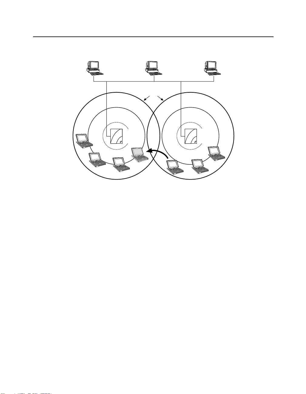
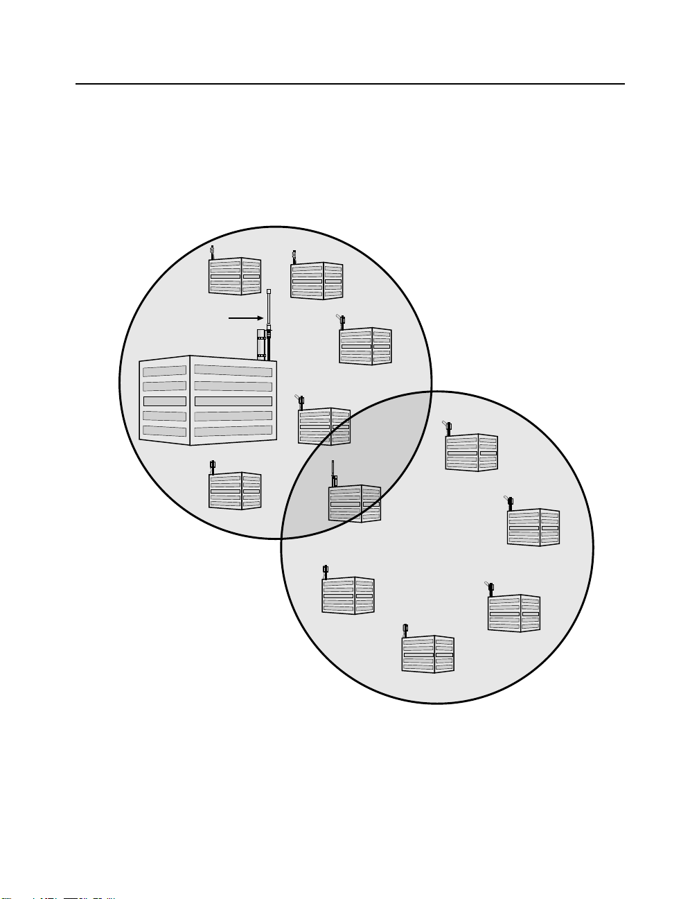
Figure 1-1 shows two APs in the same wireless network.
Page 23
Wireless Infrastructure Network
Figure 1-1: Cells Within a Wireless Infrastructure Network
Configuration
AP1
Workgroup
Mode
Coverage
Areas
AP2
Workgroup
Mode
Cell 1 Cell 2
Wireless
Client
To allow wireless clients to physically move within a wireless network, the coverage areas
should overlap. In Figure 1-1, Cell 1 and Cell 2 share overlapping areas of coverage. As a
wireless client moves from Cell 2 to Cell 1, the necessary infrastructure network
information is passed from AP2 to AP1 while maintaining LAN connectivity. The
capability of moving from one AP to another without losing the network connection is
called roaming.
When a wireless client (such as the laptop computer in Figure 1-1) approaches the outside
boundary of a coverage area, the client can sense that another AP using the same Wireless
Network Name is providing a better quality signal. The client then automatically switches
to the other AP. If the other AP is using a different channel, the client automatically
switches to that channel.
1-7
Page 24

Wireless Infrastructure Network
Wireless Client Behavior
You can configure the wireless client to connect to a specific wireless network or the first
available wireless network.
If you configure the client to connect to a specific wireless network, the client establishes
a radio connection to the AP in the specified wireless network that provides the best
communications quality. APs in a different wireless network are ignored.
If you configure the client to connect to the first available wireless network (the Wireless
Network Name = ANY), the client establishes a radio connection to the AP that provides
the best communications quality. Be aware that if there are multiple wireless networks, the
client could connect to an AP that is not in the network you want to join.
In either configuration, the client automatically matches the radio channel used by the AP.
A wireless client configured to connect to any available network does not automatically
switch networks after it makes a connection to a wireless network; for example:
Your wireless client is configured to connect to the first available wireless network.
The first available network is called SouthSide. Once the connection is made, you
move your client out of range of SouthSide, but in range of another wireless network
called NorthSide. The wireless client loses the connection to SouthSide but does not
make the connection to NorthSide. To connect to NorthSide, you need to restart the
client. After the restart, the wireless client connects to NorthSide since it is the first
available wireless network.
1-8
Page 25
LAN-to-LAN Configuration
You can connect separate LANs over a wireless link by configuring two or more
RoamAbout APs to communicate with each other. This is called a LAN-to-LAN
configuration.
There are two variations of the RoamAbout LAN-to-LAN configur ation:
• Point-to-Point, using the LAN-to-LAN Endpoint Bridge mode, which connects two
wired networks.
• Point-to-Multipoint, using the LAN-to-LAN Multipoint Brid ge m ode, which can
connect multiple wired networks.
Typically, the APs are configured with outdoor antennas. If you use an outdoor antenna,
you should have a professional antenna installation company perf orm the installation.
Contact your Enterasys sales representative or visit the RoamAbout web site,
www.enterasys.com/wireless, for more information about the outdoor antenna kits.
Point-to-Point
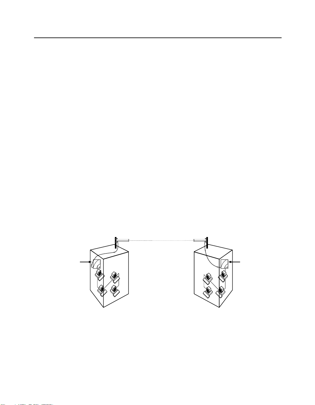
Figure 1-2 shows two APs, configured as LAN-to-LAN Endpoint Bridge mode, in
different buildings using an outdoor antenna to connect the LANs in those buildings. As
shown in the figure, both APs use a directional antenna. You can also configure the APs to
connect two LANs in the same building.
LAN-to-LAN Configuration
Figure 1-2: Point-to-Point Configuration
Endpoint
Mode
Endpoint
Mode
1-9
Page 26
LAN-to-LAN Configuration
Point-to-Multipoint
You can connect wired LANs in different buildings using the LAN-to-LAN Multipoint
feature. At least one of the APs is configured as a Multipoint AP, called the Central AP.
The Central AP can communicate directly with up to six APs. The six APs are configur ed
as Endpoints, which can only communicate directly to the Central AP. The Central AP
allows the Endpoint APs to communicate with each other through the Central AP.
A Central AP uses an omni-directional antenna so that it can communicate with multiple
APs in different directions. The Endpoint APs usually use a directional antenna pointed at
the Central AP. The directional antenna allows you to increase the distance between APs.
There must be a clear line sight between antennas to avoid a reduction in the s ignal level.
NOTE: The RoamAbout R2 Mezzanine option (slot 2) does not support
NOTE
Configuration Examples
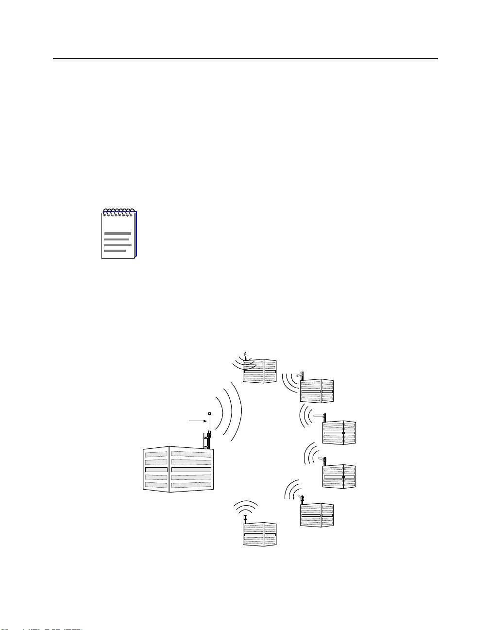
Figure 1-3 provides an example of a Central AP with six Endpoint APs. The Endpoint APs
can only communicate with the Central AP and not directly with each other. Therefore, the
Central AP should be connected to the main wired LAN.
LAN-to-LAN Multipoint. This means that an R2 can use its Slot 2 radio to
participate as an Endpoint AP in a Point-to-Multipoint configuration, but
cannot use its Slot 2 radio to act as a Central AP.
1-10
Figure 1-3: Point-to-Multipoint Configuration
Endpoint Mode
Endpoint Mode
Omni-Directional
Antenna
Multipoint Mode (Central AP)
Endpoint Mode
Endpoint Mode
Endpoint Mode
Endpoint Mode
Page 27
LAN-to-LAN Configuration
Omni-Directional
Antenna
A5
Endpoint Mode
A3
Endpoint Mode
A1
Endpoint Mode
Building A
Multipoint Mode (Central AP)
A2
Endpoint Mode
A4
Endpoint Mode
Building B
Multipoint Mode
(Central AP)
A4
Endpoint Mode
B5
Endpoint Mode
B2
Endpoint Mode
B3
Endpoint Mode
B4
Endpoint Mode
Building B
Multipoint Mode
(Central AP)
B1
Endpoint Mode
A4
Endpoint Mode
Building B
Multipoint Mode
(Central AP)
Figure 1-4 provides an example of two Central APs in the same Point-to-Multipoint
configuration. In this configuration, six APs are configured to communicate with the same
Central AP. You can configure one or more of those six APs as a Central AP to
communicate with up to five additional APs. If using an Access Point 2000, this
configuration requires the Wireless Relay parameter to be enabled.
Figure 1-4: Point-to-Multipoint-to-Multipoint Configuration
Area 1
A1
Endpoint Mode
Omni-Directional
Antenna
Building A
Multipoint Mode (Central AP)
A2
Endpoint Mode
A4
A3
Endpoint Mode
Endpoint Mode
Area 2
B1
Endpoint Mode
A5
Endpoint Mode
Building B
Multipoint Mode
(Central AP)
B5
Endpoint Mode
B4
Endpoint Mode
B2
B3
Endpoint Mode
Endpoint Mode
1-11
Page 28
LAN-to-LAN Configuration
In Figure 1-4, Building A is the Central AP for Buildings A1 through A5 and Building
B. However, Building B is also the Central AP for Build ing A and Buildings B1
through B5. You could expand this one further by making Building B3 a Central AP
for five other buildings, although adding additional hops may decrease network
performance.
To avoid bridging problems, d o not conf igure an AP as an Endpoint fo r more than one
Central AP. In Figure1-4, you would not configure Building B1 as an Endpoint to
communicate directly to Building A.
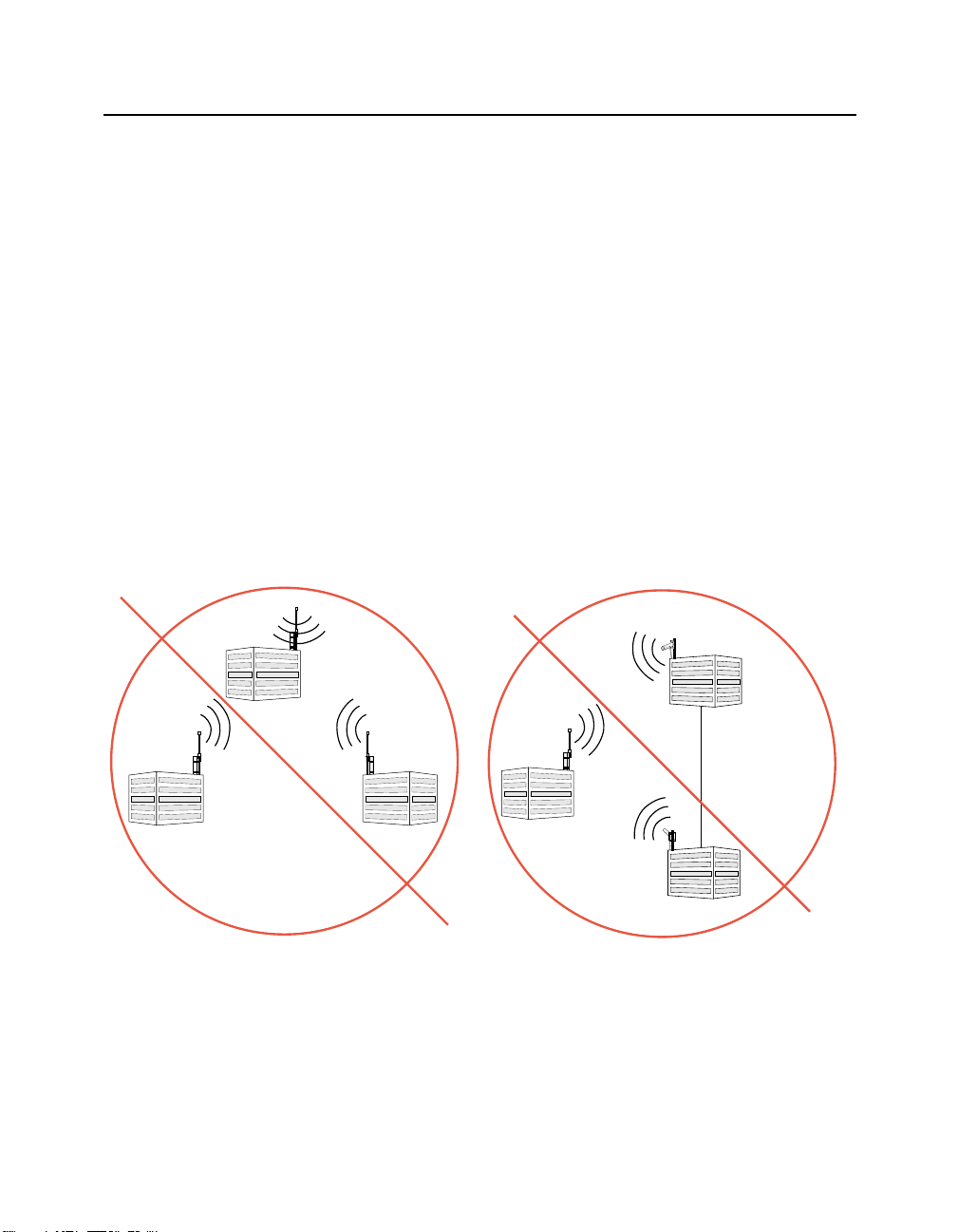
Preventing Network Loops
It is important to avoid Point-to-Multipoint configurations that will cause bridge loops. A
bridge loop occurs when two parallel network paths are created between any two LANs,
causing packets to be continuously regenerated through both parallel paths. This situation
eventually renders the network unusable due to the excessive traff ic that is being generated
by the loop. The AP Spanning Tr ee function corrects t his type of problem by s hutting down
the port and possibly shutting down a segment of the network.
Figure 1-5 provides examples of configurations that cause Network Loops.
Figure 1-5: Network Loops
Building B
Multipoint Mode
Building B
Endpoint Mode
1-12
Building A
Multipoint Mode
Building C
Multipoint Mode
Building A
Multipoint Mode
(Central AP)
Wired or Fiber Link
Building C
Endpoint Mode
Page 29
RoamAbout R2 Configuration Examples
RoamAbout R2 Configuration Examples
This section provides co nfigur ation ex amples us ing the RoamA bout R 2 (with t he two- slot
option).
Restrictions
• The RoamAbout R2 slot 2 does not support LAN-to-LAN Multipoint.
• If two 802.11b PC Cards are installed in the RoamAbout R2 Wireless Access Platform,
one of the PC Cards must be connected to the Range Extender Antenna to prevent rad io
interference between the two cards. The antenna mus t be placed at least two f eet away
from the RoamAbout R2.
• The 802.11 PC Cards must be at least 5 channels apart from each other.
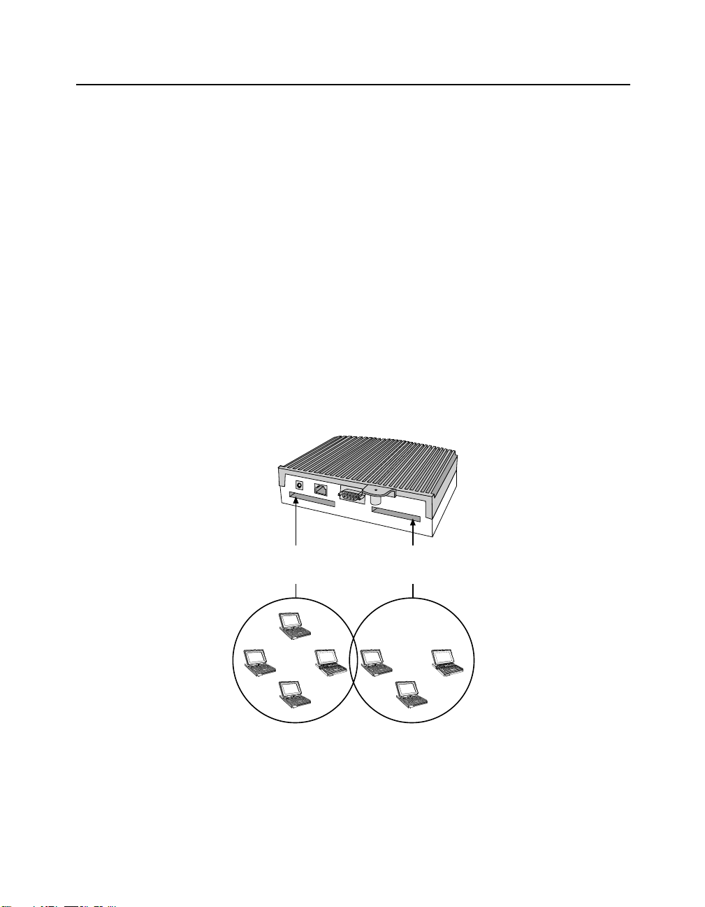
Workgroup Mode (both slots) Example
Figure 1-6 shows a RoamAbout R2 with both slots configured in Workgroup mode.
Figure 1-6: Workgroup Configuration
R2 With Mezzanine Option
Slot 2
Workgroup
Mode
Slot 1
Workgroup
Mode
WNG_21
1-13
Page 30
RoamAbout R2 Configuration Examples
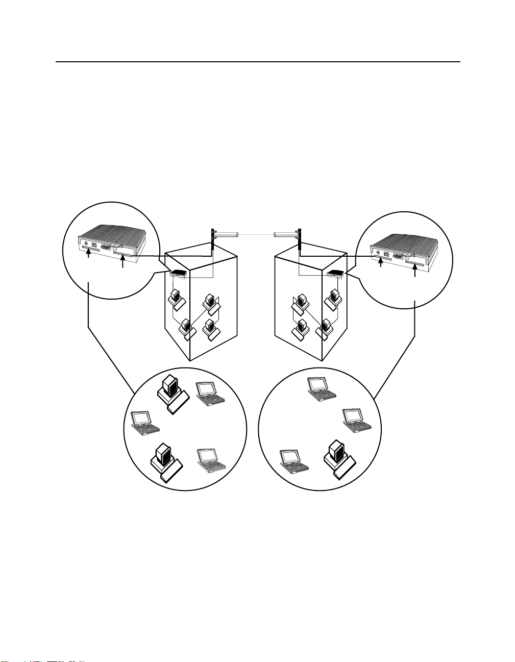
Workgroup Mode and LAN-to-LAN Example
Figure1-7 shows two RoamAbout R2 s in different buil dings using an outdo or directional
antenna to connect the LANs in those buildings. Each RoamAbout R2 contains two radio
slots; one slot configured in Workgroup mode, and one slot configured in LAN-to-LAN
Endpoint Bridge mode.
In addition, a RoamAbout R2 can be config ured for mu ltipoint mode (slot 1 o nly), connect
to an omni-directional antenna, and connect to other APs.
Figure 1-7: Workgroup and LAN-to-LAN Endpoint Configuration
Slot 2
Workgroup
Mode
R2
Slot 1
Endpoint
Mode
Slot 2
Endpoint
Mode
R2
Slot 1
Workgroup
Mode
1-14
Page 31

Ad-Hoc Network
Client D
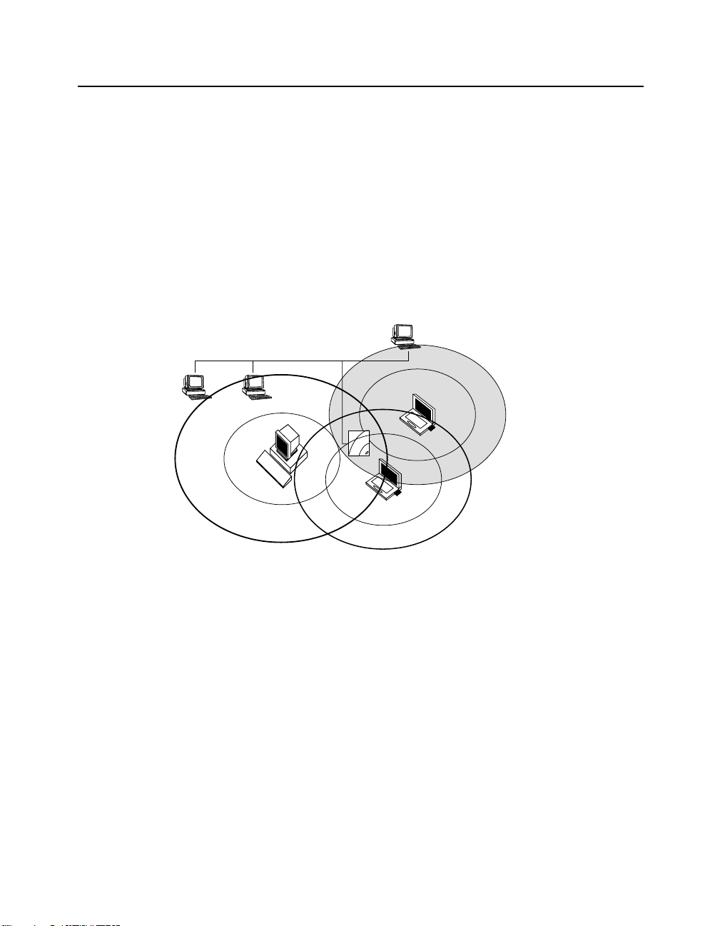
Wireless ad-hoc networks do not include APs. Instead, the ad-hoc network is a loose
association, or workgroup, of computers that can communicate with each other using the
PC Card in Ad-Hoc Mode. Figure 1-8 shows an ad-hoc network.
The ad-hoc network is also known as a peer -to-peer net work or i ndependent network . The
size of the ad-hoc network coverage area is determined by various factors, such as
proximity and obstacles in the environment. In Figure 1-8, Client D has a coverage area
(shown in gray) that touches all the other clients. This client can communicate with the
other clients. Client C’s coverage area does not touch Client A. These clients cannot
communicate unless they move closer together.
The number of clients that the ad-hoc network can support is determined by the network
utilization of each client. For example, a large number of clients could use the network fo r
reading e-mail with very good network performance, but a few clients transferring large
files could slow the network response time for all the clients.
Figure 1-8: Ad-Hoc Network
Ad-Hoc Network
Client B
Client A
Client C
Client D
1-15
Page 32

Optional Antennas
Optional Antennas
The RoamAbout PC Card has two integrated antennas that perform best in an open
environment with as few obstacles as possible. Depending on the environment and wireless
network configuration, you may need an optional antenna.
The following sections describe the types of optional antennas available with the
RoamAbout products.
Vehicle-Mount Antenn a
The RoamAbout Vehicle-Mount antenna (Figure 1-9) is a 5 dBi omni-directional antenna
that connects vehicles with an on-board client to the wireless network. The sturdy design
allows you to mount it on veh icles, such as the roof of a fork- lift truck , to all ow continuo us
access to networked data, whether inside or outside of the building.
You connect the Vehicle-Mount antenna to the PC Card using the special 2.5 meter (8 foot)
cable. To connect an antenna to the PC Card, insert the connector into the socket on the
extended side of the PC card. To protect the socket from dust, it is shielded with a cap. You
must remove the cap. For mounting and installation instructions, see the RoamAbout
Outdoor Antenna Site Preparation and Installation Guide.
Figure 1-9: Vehicle-Mount Antenna
1-16
r
te
ap
d
e
A
t
a
d
R
he
h
c
ig
at
H
M
S
t
i
D
b
a
.1
2
ig
80
i-G
H
i
iF
G
N
I
K
R
O
W
T
W
S
N
A
L
S
S
E
L
E
E
N
R
I
S
W
S
E
L
E
R
I
W
F
O
M
O
D
E
E
R
F
E
H
T
Y
O
J
N
E
WNG_07
Page 33

Optional Antennas
Range Extender Antenna
Use the Range Extender Antenna (Figure 1-10) to ensure optimal transmission and
reception quality for situations where the integrated antennas are shielded, such as:
• The wireless device, such as a desktop client, is close to metal surfaces.
• The wireless device is installed in a hidden location, such as in a cabinet.
• Objects shield the wireless device.
• Using the RoamAbout R2 Mezzanine slot upgrade option, where two 802.11b PC
Cards are installed in the RoamAbout R2 Wireless Access Platform. One of the PC
Cards must be connected to the Range E xtender Antenna to preven t radio interfer ence
between the two cards. In this case, the antenna must be placed at least two f eet away
from the RoamAbout R2.
The Range Extender antenna has a mounting bracket and a base for vertical positioning that
allows you to place the antenna on top of a table or cabinet, or attach it to the wall or ceiling.
To connect an antenna to the PC Card, insert the connector into the socket on the extended
side of the PC card. To protect the socket from dust, it is shielded with a cap.
CAUTION: To avoid damage, do not place the Range Extender Antenna on
top of, or cl ose to a monitor. Many computer monitors have a degauss
option. An electromagnetic discharge that may occur when degaussing the
monitor may damage the antenna.
Figure 1-10: Range Extender Antenna
r
e
t
p
a
d
e
t
A
a
d
R
e
h
h
g
c
i
t
a
H
M
S
t
D
i
b
1
.
a
2
g
i
0
8
G
i
H
G
i
N
I
F
K
i
R
S
O
N
W
W
A
T
L
E
S
N
S
E
S
L
S
E
E
R
L
I
E
W
R
I
W
F
O
M
O
D
E
E
R
F
E
H
T
Y
O
J
N
E
WNG_08
1-17
Page 34

Optional Antennas
Outdoor Antenna Kit
There are two RoamAbout antennas available for outdoor use:
• 14-dBi directional antenna
• 7-dBi omni-directional antenna
The RoamAbout outdoor antennas support outdoor LAN-to-LAN wireless links that are
used to connect separate LANs. The directional antenna is typically used in a Point-to-Point
wireless link. The omni-directional antenna is typically used in a Point-to-Multipoint
configuration. The omni-directional antenna can also be used in a wireless infrastructure
network.
Refer to the RoamAbout Outdoor Antenna Site Prepara t ion a nd Installation Guide, or the
RoamAbout web site for more information: http://www.enterasys.com/wireless.
1-18
Page 35

Understanding Wireless Network
This chapter describes many of the wireless networking co ncepts and cha racteristics. You
should be familiar with this information before you design, implement, or manage a
RoamAbout wireless network. Not all characteristics apply to all o f the net w ork
configurations.
Some of the features listed are not available with earlier vers ions of the AP and the PC Card
driver. Review the Release Notes to determine if a feature is sup ported by your AP version
and client version.
In This Chapter
Information in this chapter is presented as follows:
Topic Page
Wireless Network Name 2-2
Access Point MAC Addresses 2-3
RoamAbout R2 MAC Addresses 2-3
Channel Frequencies 2-4
Transmit Rate 2-5
Communications Qual ity 2-7
Data Throughput Efficiency 2-8
AP Density and Roaming 2-8
RTS/CTS Protocol 2-9
802.11 Power Management 2-11
Security 2-12
Network Operating System Security 2-12
RoamAbout AP Secure Access 2-12
Chapter 2
Characteristics
2-1
Page 36

Wireless Network Name
Topic Page
Wired Equivalent Privacy (WEP) Encryption 2-13
Authentication 2-14
802.1X Rapid Rekeying 2-16
SNMP Community Names 2-19
Console Port Security 2-19
Network Protocols 2-20
Wireless Traffic 2-20
Spanning Tree Protocol 2-22
VLANs 2-23
RoamAbout SNMP Management 2-26
Wireless Network Name
A wireless network name, also called an SSID, is the name of the wireless infrastructure
network. To add an AP to an existing w ireless network , configur e the AP with the name of
the wireless network. To create a new wireless infrastructure network, configure the AP
with a unique wireless network name. The wireless network name is case sensitive.
2-2
The AP has a Secure Access feature. When enabled, the AP do es not broadcast its networ k
name, and it only accepts connections from clients configured with the correct name. Users
of operating systems like Windows XP will not see the name sh ow up automatically in
wireless LAN configuration dialogs.
When Secure Access is disabled, users can configure clients without a network name by
leaving the network name field blan k or using ANY (all uppercase) as the wireless network
name, and still connect to the network. Users of operating systems like Windows XP will
be able to vie w the networ k name in wireless LAN configuration dialogs.
The AP does not use a wireless network name in a LAN-to-LAN configuration.
Page 37

Access Point MAC Addresses
The MAC address is a unique identifier for networking devices. Each LAN device
(including Ethernet cards, bridges, routers, and gateways) is identified by a unique
factory-set MAC address:
• One MAC address for the wired Ethernet interface, which is printed on the AP.
• One MAC address for the RoamAbout PC Card installed in the AP, which is printed
on a label on the back side of the card.
RoamAbout wireless clients are identified by the MAC address of the RoamAbout PC
Card. You cannot change the universal MAC address of a networking device.
RoamAbout R2 MAC Addresses
The RoamAbout R2 has the following MAC Addresses allocated to it:
• One MAC address for the wired Ethernet interface, which is printed on the AP.
• One MAC address for each RoamAbout PC Card installed in the AP, which is printed
on a label on the back side of the card.
• One MAC address for the Spanning Tree. This MAC address is the wired MAC
address plus 10 hex. For example, if the RoamAbout R2 MAC Address is
xx-xx-xx-xx-xx-40, the Spanning Tree MAC Address will be xx-xx-xx-xx-xx-50.
Access Point MAC Addresses
If using SNMP, you may see additional MAC Addresses, starting with the MAC address
printed on the AP. These additional 30 MAC Addresses are used internally and do not
generate network traffic.
2-3
Page 38

Channel Frequencies
Channel Frequencies
The channel sets the center radio frequency for the wireless device. The RoamAbout PC
Card can support up to 14 channels; however, the number of available channels varies in
different countries.
• APs within the same wireless infrastructure network can be set to differ ent channels.
You can change the channel in an AP. Th e client automatically uses the same chan nel
as the AP.
• Wireless clients automatically switch to the AP’s channel when roaming between APs
in a wireless network; for example, there are two APs in a wireless network where
AP 1 uses channel 1 and AP 2 uses channel 6. When connected to AP 1, the client
automatically uses channel 1. When roaming to AP 2, the client automatically changes
to channel 6.
• To avoid radio interference, adjacent APs should be set to different channels that are
at least five channels apart. The APs do not necessarily have to be in the same wireless
network. For example, you have three APs whose coverage areas overlap; set the
channels to 1, 6 and 11, if possible.
Due to local radio regulations, not all channels are available in all countries.
NOTE
• In a LAN-to-LAN configuration, the APs must be set to the same channel.
• In an Ad-Hoc network, all clients must use the same channel to communicate. The
client uses a default channel which cannot be changed, with the exception of Mac and
Windows XP clients. You can set the channel on Mac and Windows XP operating
systems.
See “Supported Frequency Sub-Bands” on page A-3 for a list of channels s uppor ted by
country.
NOTE: If you have two 802.11b PC Cards installed in the RoamAbout R2,
the channels between the PC Cards must be at least 5 channels apart from
each other.
2-4
Page 39

Transmit Rate
The transmit rate identifies the preferred data transmission speed of the AP. The actual data
transmission speed is subject to the type of PC Cards at both ends of the wireless link and
the communications quality of the link.
Transmissions at faster rates allow for higher data throughput and quicker net work
response times. However, transmissions at lower rates are usually more reliable and cover
longer distances than the higher rates. You might use a lower rate when the client is at the
extreme edge of the coverage area (see Figure 2-1). Using a lower rate covers the longer
distance more reliably than a higher rate.
As shown in Figure 2-1, an AP can have clients using different transmit rates in a wireless
infrastructure network.
The following sections describe the auto rate and fixed rate settings.
Figure 2-1: Using Various Transmit Rates
Transmit Rate
Fixed
Higher
Rate
Lower
Rate
Intermittent
Noise
Higher
Rate
2-5
Page 40

Transmit Rate
Auto Rate
With the auto rate option, the PC Card in a client or AP automatically switches to the next
lower rate when data transmissions fail more than once. Shortly after completing the
transmission, the PC Card returns to transmitting dat a at the higher rate.
In most environments, Auto Rate allows the PC Card to use a higher rate for better data
throughput, yet the PC Card can still use the more reliable slower rate when transmissions
fail. A transmission can fail when the network experiences sporadic noise interference.
Also use Auto Rate if you have APs with 11 Mbit/s PC Cards and a mix of clients with
11 Mbit/s and 2 Mbit/s PC Cards. The AP can communicate with both types of clients, but
can communicate with the 11 Mbit/s clients at a higher rate than the 2 Mbit/s clients.
Fixed Rate
A fixed rate setting prevents the PC Card from retransmitting at a lower rate after a failed
transmission. One example of why you would do this is when a microwave oven in the area
produces noise in the same frequency as the wireless network (see Figure 2-1). The
interference only occurs when the machine is in use. The interference may temporarily
disrupt communications between a client and the AP.
After a transmission fails more than once, the AP retransmits at a lower rate. However, the
interference also prevents communication at the lower rate. Retransmitting at a lower rate
does not solve the problem and could decrease network performance. With fixed rate
enabled, the AP cannot retransmit at a lower rate.
2-6
Using a fixed low rate is useful in networks where range is more important than speed,
especially when network response times are affected by numerous retransmissions and the
communications quality is low due to a low signal level. Setting the transmit rate to a low
rate prevents the AP from slowing network response times by transmitting data
unsuccessfully at a higher rate then retransmitting at a lower rate.
A fixed transmit rate does not affect the receive rate. For example, an AP and a client bo th
have 11 Mbit/s PC Cards, but the client is fixed to only transmit at 2 Mbit/s. The AP can
send data at 11 Mbit/s to the client, and the client can respond by sending data at 2 Mbit/s.
You should not set the AP to a fixed rate of more than 2 Mbit/s if you have clients with
11 Mbit/s and 2 Mbit/s PC Cards. Otherwise, the 2 Mbit/s clients cannot communicate with
the AP. The 2 Mbit/s clients can only receive data at a maximum of 2 Mbit/s.
Page 41

Communications Quality
Communications quality is measured by the Signal to Noise Ratio (SNR). The SNR is a
dynamic indicator that indicates the relative strength of the radio signal (signal level) versus
the radio interference (noise level) in the radio signal path. In most environments, SNR is
a good indicator for the quality of the radio link between transmitter and receiver. A higher
SNR value means a better quality radio link.
The RoamAbout Client Utility allows you to monitor the SNR, signal level, and noise level
at the client. The Client Utility is provided on the RoamAbout 802.11 PC Card Drivers and
Utilities CD-ROM, or you can download it from the RoamAbout Wireless web site.
For the AP, the RoamAbout AP Manager prov ides a Link Test diagnostic tool th at monitors
the SNR, signal level, and noise level between the AP and a remote wireless device.
Signal Level
The signal level values give you an indication of the distance between wireless devices.
Using the RoamAbout Client Utility, you can observe a decrease of the signal level value
when you move a client away from its AP. As an indicator for the communications quality,
signal level should always be interpreted in combination with noise level:
• A high signal level with a low noise level provides excellent communi cations quality.
• A high signal level with a high noise level results in an average or poor SNR.
Communications may not be as good as expected despite the strong signal level.
• A low signal level may still provide adequate communications when the noise level is
relatively low.
Communications Quality
Noise Level
The noise level indicates the presence of interference. Noise can be generated by various
devices such as microwave ovens (2.4 GHz), elevator mo tors, and theft detection devices
(like those used in retail stores). Noise level should always be related to the signal level:
• A low noise level w ith a hig h sign al level p rovid es excell ent commun icatio ns qual ity.
• A medium or high noise le vel with a high si gnal level results in an average or poo r
SNR. Communications may not be as good as expected despite the s trong si gnal level.
• A high noise level most likely provides poor communications when the signal level is
medium or low.
2-7
Page 42

Data Throughput Efficiency
Data Throughput Efficiency
Data throughput efficiency is measured in transmissions sent, lo st, or received. When a data
transmission fails, the wireless device automatically ret ransm its the data. It is normal in
many environments for a transmission to fail occasionally. Data is not lost since the
wireless device automatically retransmits the data frames.
Many failed transmissions may result in longer network response times. Numerous
retransmissions require more time and bandwidth to maintain network communication
while contributing to the congestion of the medium. You can determine the number of
retransmissions in a wireless network using the RoamAbout Client Utility. The client utility
is provided in the RoamAbout PC Card kit and is installed on clients.
AP Density and Roami ng
The AP Density is an advanced value that changes the sensitivity of th e roaming client. The
distance range between RoamAbout APs listed below are estimated, and may differ
depending on your operating environment.
• Low (default). The Low setting provides maximum coverage using a minimum
number of APs. This option is typically used for single-cell networks, but also provides
an efficient and cost effective solution for networks that include multiple wireless
clients. The coverage area ranges up to approximately 60+ meters.
2-8
• Medium. The Medium setting can be used for environments where you desire clients
to disassociate sooner and roam to communicate at shorter distances/higher speeds
than the Low setting. The coverage area ranges approximately 40 to 60 meters.
• High. The High setting should only be used when you are designing a wireless
infrastructure that includes a high concentration of AP devices. The coverage area
ranges approximately 20 to 40 meters.
• Minicell. The Minicell setting should be us ed when you want to creat e small coverage
areas. The coverage area distance range is approximately 10 to 20 meters.
• Microcell. The Microcell setting should be used when you want to create extremely
small coverage areas. The distance range is approximately 5 to 10 meters.
The AP has a Medium Density Di stribution parameter that automatically distri butes the AP
density setting to the RoamAbout wireless clients with the V7.44, or higher, driver. This
parameter is enabled by default.
Page 43

RTS/CTS Prot ocol
Each device in a wireless n etwork can sense transmi ssions from other dev ices in its network
that use the same frequency. To avoid collisions and lost data, a device only transmits when
it senses that no other device is transmitting. This behavior is referred to as the Carr ier
Sense Multiple Access/Collision Avoidance (CSMA/CA) protocol. The RTS/CTS
(Request to Send/Clear to Send) protocol is useful when collisions do occur. Collisions can
occur if two clients are unable to sense each other’s transmissions and simultaneously
transmit to the AP.
The RTS/CTS protocol forces a wireless device to perform the following:
• When a packet to be transmitted is shorter than the RTS/CTS thresh old, the device
transmits when it senses that the medium is free. The RTS/CTS protocol is not used.
A shorter packet is less likely to have a collision than a longer packet.
• When the packet exceeds the threshold, the device sends an RTS message and waits
until the receiving device responds with a CTS message.
The RTS message includes the length of the frame that the device wishes to transmit. The
receiving device includes this information as a radio-silence time indicator in its CTS
response message. The CTS message announces to all the d evices in the wir eless networ k
which device is allowed to transmit its message. All other devices defer their transmissions
for the radio-silence time identified in the CTS message.
RTS/CTS Protocol
The RoamAbout AP allows you to set the RTS Threshold on the AP, and to set a Remote
RTS Threshold for clients to avoid a hidden station problem.
RTS Threshold
The RTS Threshold on a RoamAbout AP specifies the packet size of transmissions, where
messages larger than the specified size must use the RTS/CTS protocol. Th e default value,
2347, effectively turns off the RTS Threshold.
A lower RTS Threshold is useful when collisions frequently occur at the AP. This can be
caused when the AP and a client (or AP in a LAN-to-LAN configuration) transmit data to
each other simultaneously. A lower RTS Threshold forces the AP to send an RTS to the
device before transmitting a packet that exceeds the threshold. The AP waits until the
device responds with a CTS message.
Lowering the RTS Threshold imposes additional network overhead that could negatively
affect the throughput performance. You should only lower the RTS Threshold when the
wireless network experiences frame collisions and lost messages.
2-9
Page 44
RTS/CTS Protocol
Client B
Hidden Station
A wireless device is a hidd en station when its transmissions cannot be sensed by another
wireless device in the same network. Therefore, multiple devices could transmit at the same
time. This problem can occur with clients located at opposite ends of an AP coverage area.
Figure 2-2 illustrates a hidden station example. Clien ts A and B are within range of the AP.
However, Client B cannot sense transmissions from Client A, since Client A is outside of
Client B’s coverage area (shown in gray). Client B could transmit while Client A is
transmitting. Therefore, messages of both Client A and B collide when arriving
simultaneously at the AP. The collision results in a loss of messages for both clients.
Figure 2-2 also illustrates that Client C is not hidden from the other clients.
Figure 2-2: Hidden Station Example
Client B
2-10
Client A
Client C
To avoid a hidden station problem, move the clients or AP if possible so that the devices
can sense each other’s transmissions. Othe rwise, enable Remote RTS Threshold on the AP.
Do not change the RTS Threshold on the AP.
Enabling Remote RTS Threshold forces the client to send an RTS to the AP before
transmitting a packet that exceeds the threshold. The client waits until the AP responds with
a CTS message. However, enabling Remote RTS Threshold imposes additional network
overhead that could negatively affect the data throughput performance. You should only
use this setting when the density of clients and APs is low and you witness poor networ k
performance due to excessive frame collisions at the APs.
Page 45

802.11 Power Manag ement
Power management can extend the battery life of clients by allowing the client to sleep for
short periods of ti me while its messages are buffered by the AP.
You may need to balance wireless performance versus battery-life. Power management
imposes a more active use of the wireless medium, which might lead to more frequent
transmission delays experienced as slower network response times during file transfers.
With slower response times, the client may spend more time in operational mode resulting
in less effective power management. In such cases, disabling power management on the
client might result in better throughput performa nce.
The RoamAbout PC Card 802.11 power management is separate from any power
management function on your compu t er.
RoamAbout AP
The RoamAbout AP automatically supports 802.11 power management. The only
parameter that can be set is the Delivery Traffic Indication Message (DTIM) interval,
which sets the buffering time. The default value of 1 corresponds to 100 milliseconds of
sleep time. It is highly recommended that you do not change this value.
RoamAbout Client
You can enable or disable power management on a RoamAbout client. With power
management enabled, the client goes into sleep mode to minimize power consumption. The
wireless traffic is buffered in the AP that the client uses to connect to the network.
802.11 Power Management
The client checks for network traffic addressed to the client at regular intervals. If there is
no traffic addressed to the client, the client returns to sleep mode. If traffic is buffered at the
AP, the client collects the buffered messages prior to returning to sleep mode. The
following discusses how power management can impact data throughput of the wireless
network.
• Power management causes little or no difference in network performance when using
transaction processing applications, such as hand-held scanners or clients that us e the
wireless network only to send and receive e-mail.
• You may experience longer network response times when you transfer large files
between the network and the client while power management is enabled. The size of
the files and the recurrence of file transfers are a factor. If modifying a document over
the network, any auto save feature could cause frequent file transfers.
• The AP could cause longer network response times if a number o f clients use the same
AP for buffering messages while in sleep mode.
2-11
Page 46

Security
Security
The following lists the types of security in a RoamAbout wireless envi ron ment:
• Network operating system security
• RoamAbout AP Secure Access
• Wired Equivalent Privacy (WEP) Encryption
• Simple Network Management Protocol (SNMP) community names
• SNMPv3 (RoamAbout R2 only)
• Device Authentication, which requires a RADIUS (Remote Authentication Dial-In
• 802.1X Rapid Rekeying
• Console port password
• Address Filtering (see “Filters” on page 2-21)
User Service) server. Authentication can be based on:
— MAC address
— 802.1X
— Both MAC address and 802.1X
Network Operating System Security
To access networking data or services, a wireless client needs to run an appropr iate network
operating system. Most network operating systems use stand ard security measures s uch as
login names and passwords. When you follow the standard network security procedures
and guidelines recommended for your network operating system, an unauthorized user
cannot access network data or services without the appropriate user name and password.
For detailed information, consult the documentation that came with the network operating
system or refer to the reseller of your LAN software.
RoamAbout AP Secure Access
When Secure Access is enabled, the AP denies access to wireless clients that do not use the
correct wireless network name. In add ition, the AP does not broadcast its network name, so
that clients with operating systems like Windows XP do not see the name show u p in
wireless LAN configuration dialogs.
When disabled, users can configure clients by leaving the network name field blank or
using ANY (all uppercase) as the wireless network name, and st ill connect t o the netw ork.
Clients will be able to view the network name in wireless LAN configuration dialogs.
2-12
Page 47

Wired Equivalent Privacy (WEP) Encryption
The WEP feature encrypts all data transmitted within the wireless network. The encryption
uses the RC4 algorithm as defined in the IEEE 802 .11 Wired Equ i valent Privacy s tandard.
Security
NOTE
NOTE: Broadcast and multicast messages are not encrypted.
The RoamAbout devices can be configured with four encryption keys. Each key is placed
in a specific position (Key 1, Key 2, Key 3, or Key 4). You select one key to encrypt
transmitted data. To decipher th e data, the receiving wireless dev ice must have the key used
to encrypt the data in the same position as the sending device.
The receiving device can transmit data back to the sending device using a different key for
transmission, as long as the other device has the transmitting key in the sam e position. In
Figure 2-3, the AP uses Key 1 to encrypt transmitted data, which the client can decipher.
The client uses Key 2 to encrypt transmitted data, which the AP can decipher. If the AP
uses Key 3 to encrypt tran smitted data, it cann ot be deciphered by the cli ent. The Bobss key
is Key 3 on the AP but Key 4 on the client.
Figure 2-3: Using Encryption
Key 1 = Je3ff
Key 2 = Vicki
Key 3 = Bobss
Key 4 = [No Entry]
Transmit Key = 2
Transmit Key = 1
Key 1 = Je3ff
Key 2 = Vicki
Key 3 = Freds
Key 4 = Bobss
In a wireless infrastructure network, you can configure the APs to:
• Only accept encrypted data from clients. Only clients that have the correct encryption
keys can participate in this network.
• Accept encrypted data from clients with encryption enabled, and unencrypted data
from clients without encryption enabled. This allows clients who require security to
use encryption without preventing other clients from using the network.
In a LAN-to-LAN configuration, use encryption to hav e a secure wireless link. In an ad-hoc
network, use encryption to prevent uninvited users from joining the network.
2-13
Page 48

Security
Authentication
The RoamAbout AP supports authentication of wireless workgroup clients. An AP can
authenticate clients based on:
• MAC address
• 802.1X
• Both MAC address and 802.1X (Hybrid authentication)
When using any of these types of authentication, you must configure the AP as a RADIUS
client.
RADIUS Client
RADIUS (Remote Authentication Dial In User Service) is a protocol that the AP uses to
communicate with a remote Authentication Server. Separating the Authentication Server
from the AP means that several APs can share the same centralized authorization database.
However, it also means that to successfully authenticate wireless clients, you must
configure the AP as a RADIUS client.
When configured as a RADIUS client, the AP passes user authentication information to a
designated RADIUS Server. The RADIUS Server receives inbound user connection
requests, processes the requests to authenticate the user, then responds to the AP with the
necessary information to deliver service to the user. The AP acts on the response that is
returned by the RADIUS Server to allow or deny the user’s access to the network.
2-14
The AP and RADIUS Server authenticate transactions through the use of a shared secret,
which is never sent over the network. They use the shared secret to encrypt RADIUS
attributes containing passwords or other sensitive data. This network security greatly
reduces the possibility of disclosed passwords or divulg ed secrets.
If you enable authentication on the AP without configuring it as a RADIUS client, the AP
will be unable to contact the Authentication Server. Therefore, the AP will assume that all
of the clients on the controlled ports are unauthorized and will prevent access to the LAN.
MAC Address Authentication
MAC address authentication is a form of authentication that does not place any special
requirements upon cl ie nts. The RADIUS Server is configured with the MAC address es of
the wireless clients. When a client associates with the wireless LAN, the AP uses the
client’s MAC address as the user name. The client is unaware that a MAC address
authentication is taking place, except to the extent that the AP blocks LAN access as a
result.
Page 49

Security
802.1X Authentication
IEEE 802.1X authentication allows logins based on user name, pass word, user certificates,
and other methods that may be mutually supported by the authentication server and the
clients. Only clients that support 802.1X can participate in a wireless network that uses this
type of authentication.
IEEE 802.1X authentication also imposes more requ irements on the RADIUS server. For
MAC address authentication, a RADIUS server only needs to handle RADIUS. For
802.1X, the server must also handle EAP (Ex tensib le Authen tication Protoco l) an d o ne o r
more protocols, such as MD5 (Message Digest 5) or TLS (Transport Layer Security).
Microsoft Windows 2000 Ad vanced Server is o ne example of a prod uct that support s all of
the protocols needed for 802.1X.
Some login methods associated with IEEE 802.1X provide a way by which an AP can
securely distribute radio keys. When all of the clients on a wireless LAN use such login
methods, it becomes practical to use Rapid Rekeying. Rapid Rekeying enhances security
by frequently changing radio encryption keys, reducing the time to decode and use an
encryption key.
Hybrid Authentication
Hybrid authentication is a special authentication mode for sites undergoing a transition to
IEEE 802.1X. The AP uses both MAC address and 802.1X authentication. 802.1X takes
precedence, but in the absence of 802 .1X replies fr om a clien t, the AP grants access based
on the MAC address. Th is allo ws you t o introdu ce IEEE 802.1 X clients without disrupt ing
non-802.1X clients’ access to the LAN. However, this prohibits the use of the Rapid
Rekeying feature.
Rapid Rekeying is not available in this authentication mode. The MAC address clients
would not be able to keep up with the radio key changes, and would lose connectivity to
the LAN.
2-15
Page 50

Security
802.1X Rapid Rekeying
Rapid Rekeying, also known as Key Tumbling, provides automatic IEEE 802.11 WEP
encryption key generation and frequent redistribution of WEP keys.
The following information applies to using Rapid Rekeying:
• Rapid Rekeying requires the use of 802.1X authentication. Unauthenticated clients and
MAC address authentication clients cannot receive updated WEP keys, and would
soon lose connectivity to the LAN.
• Rapid Rekeying automatically disables user-specified WEP encryption keys.
• Rapid Rekeying requires t he use of an EAP login method that generat es sess ion keys,
and the use of a RADIUS server that will distribute those keys to the AP. The AP uses
the session keys t o encrypt the WEP key di stribution messages. Clients without s ession
keys do not get new WEP keys.
• EAP-TLS authentication using X.509 certificates on the clients will work with Rapid
Rekeying.
• EAP-MD5 password authentication will not work with Rapid Rekeying. EAP-MD5
does not negotiate sessio n keys.
• Token based authentication will work with Rapid Rekeying if the token based
authentication uses a TLS based method, such as TTLS or PEAP. The requirement is
that there are TLS session keys negotiated and retained by the client and the AP.
2-16
The following describes how the AP introduces new key pairs.
1. The AP and clients are using the existing key s at the beginning of the Rapid Rekeyi ng
encryption cycle.
AP Client
Key # Encryption TX/RX State TX/RX Encryption
Key1 aaaaaaaaaaaaaa RX Active TX aaaaaaaaaaaaaa
Key2 bbbbbbbbbbbbb TX Active RX bbbbbbbbbbbbb
Key3 xxxxxxxxxxxxx Inactive xxxxxxxxxxxxx
Key4 xxxxxxxxxxxxx Inactive xxxxxxxxxxxxx
Page 51

Security
2. The key period expires. The AP creates two new random keys and loads them into the
inactive authenticator key indexes (Keys 3 and 4 in this exampl e). The keys are not yet
used for transmission or reception.
AP Client
Key # Encryption TX/RX State TX/RX Encryption
Key1 aaaaaaaaaaaaaa RX Active TX aaaaaaaaaaaaaa
Key2 bbbbbbbbbbbbb TX Active RX bbbbbbbbbbbbb
Key3 cccccccccccccc Inactive xxxxxxxxxxxxx
Key4 ddddddddddddd Inactive xxxxxxxxxxxxx
3. The AP begins transmitting the new key pair to the authenticated clients in the
supplicant list. When a client receives the new keys, it immediately begins transmitting
using the new TX key. The AP does not use the new TX key until the message has been
transmitted to all clients. During this time, the AP accepts transmissions on both the
old and new RX keys. Note that a client can only have one TX key. The following table
shows that some clients use Key1 as the TX key while other clients use Key 3.
AP Client
Key # Encryption TX/RX State TX/RX Encryption
Key1 aaaaaaaaaaaaaa RX Active TX aaaaaaaaaaaaaa
Key2 bbbbbbbbbbbbb TX Active RX bbbbbbbbbbbbb
Key3 cccccccccccccc RX Active TX cccccccccccccc
Key4 ddddddddddddd Inactive ddddddddddddd
2-17
Page 52

Security
4. Once the AP transmits the new keys to all clients in the supplicant list, it begins using
the new TX key (Key4). At this time all supplicants are using Key3 as their TX key.
AP Client
Key # Encryption TX/RX State TX/RX Encryption
Key1 aaaaaaaaaaaaaa Inactive aaaaaaaaaaaaaa
Key2 bbbbbbbbbbbbb Inactive bbbbbbbbbbbbb
Key3 cccccccccccccc RX Active TX cccccccccccccc
Key4 ddddddddddddd TX Active RX ddddddddddddd
5. The key period expires. The AP creates two new random keys, loads them into the
inactive authenticator key indexes (Keys 1 and 2 in this example), and repeats the
process (starting at step 3).
AP Client
Key # Encryption TX/RX State TX/RX Encryption
Key1 eeeeeeeeeeeee Inactive aaaaaaaaaaaaaa
2-18
Key2 fffffffffffff Inactive bbbbbbbbbbbbb
Key3 cccccccccccccc RX Active TX cccccccccccccc
Key4 ddddddddddddd TX Active RX ddddddddddddd
Page 53

SNMP Community Names
The SNMP community name al l ows man agemen t t ools us i ng SNMP t o di s play or modify
AP parameters remotely.
The RoamAbout R2 supports SNMPv3. To access the RoamAbout R2 parameters via
SNMP, the management tool must know the Authentication Password and Privacy
Password. To support managemen t tools using SNMPv2 or SNMPv1, the R2 provides four
community names that allow SNMPv1 and SNMPv2c read -only and read-write access. The
names are disabled by default with the exception of Community Name #1, which is set to
public. The community names are only accessible from the R2 console port.
The AP 2000 supports a read/write community name and a read-on ly community name. By
default, the AP uses public as the default read/write community name. This allows any
management tool using SNMP to access the AP and change parameters. By changing the
read/write community name, users must enter the correct community name to modify the
AP parameters. The read-onl y co mmun i ty name allows the management tools to v ie w but
not change the AP parameters. You can change th e read-only name so that users must enter
the correct name before they can view the AP parameters.
Console Port S ecurity
RoamAbout Access Point 2000
Security
The RoamAbout Access Point console port has two security featur es:
• You can configure the console port to require a password before users can access the
Installation Menu.
• You can configure the console port to prevent any management system from using
SNMP to modify the encryption parameters.
RoamAbout R2
The RoamAbout R2 console port supports SNMPv3, and has the following security
features:
• Access to the console requires a password. The username is “admin” and the default
password is “password”. The password must be a minimum of eight ASCII characters,
and is case-sensitive.
• The ability to enable or disable Web management and Telnet.
2-19
Page 54

Network Protocols
Network Protocols
When you install a RoamAbout PC Card in a computer using a Windows operating system,
you may need to install and configure a s et of netw orking proto cols. The t ype of p rotoco ls
needed depends on the network operating syst em used within your LAN environment. Th e
most common protocols are:
• IPX/SPX compatible protocols if your networking environment is using the Novell
NetWare network operating system.
• NetBEUI if you want to use file and print sharing supported by Microsoft Client for
Microsoft N etworks.
• TCP/IP if you want to connect your computer to a network that uses IP addressing or
you would like to connect to the Internet.
These networking protocols can operate simultaneously with other networking protocols.
When you install a Ro amAbout PC Card in an Apple computer, yo u may need to in stall and
enable Apple’s Open Transport or Apple Classic network protocols along with TCP/IP.
Wireless Traffic
In addition to data, wireless network traffic includes beacons and various types of
messages.
2-20
Beacons
A beacon is a message that is transmitted at regular intervals by the RoamAbout APs to all
wireless clients in the wireless infrastructure. Beacons are used to maintain and optimize
communications by helping mobile RoamAbout clients to automatically connect to the AP
that provides the best communications quality.
Beacons are transmitted at 2 Mbit/s when the transmit rate is set to auto rate, as described
in “T ra ns mi t Rate” on page 2-5. If the transmit rate is fixed, the beacons are transmitted
at the fixed rate.
Page 55

Wireless Traffic
Message Types
When a device in the wireless network transmits data, it can take one of these forms:
• Broadcast: A data message transmitted by one device to all devices in the network.
• Multicast: A data message transmitted by one device to multiple devices in the
network. Unlike broadcast messages, multicast messages do not always include all
devices in t he network.
• Unicast - A data message transmitted by one device to another device.
Broadcast and multicast messages are transmitted at 2 Mbit/s when the transmit rate is set
to auto rate, as described in “Transmi t Rate” on pa ge 2-5. If the transmit rate is fixed, the
broadcast and multicast messages are transmitted at the fixed rate.
Filters
The following filters are only available using the RoamAbout AP Manager, or a Network
Management Station that uses SNMP.
The RoamAbout AP has three types of filters:
• Protocol
Use the Protocol filter to NOT forward specific protocol traffic to the wireless
network, which can reduce unnecessary traffic and increase the network response time.
However, filtering the wrong protocols can negatively affect the operation of the
network. When solving network problems, you should clear all filters.
• Address
This filter forwards or does not forward traffic based on the client’s MAC address.
— Addresses Denied: A client in the Addresses Denied list cannot access the LAN,
even if the client has been authenticated.
— Addresses Allowed: Clients in the Addresses Allowed list can access the LAN.
Clients must supply their MAC address to the Network Administrator. This filter
is essentially ineffective when also using authentication.
• Rate Limiting (AP 2000 only)
Use rate limiting to enable/disable the default rate limiting, and to enter the maximum
number of rate-limited frames forwarded per second.
By default, the AP 2000 limits multicast traffic to 100 Kbit/sec. Chan ging this
parameter could cause multicast traffic to use more network bandwidth. Should a
broadcast storm occur when this parameter is disabled, the multicast traffic could cause
a serious degradation of network performance. The R2 does not support the mul ticast
rate limiting function.
2-21
Page 56

Spanning Tree Protocol
Spanning Tree Protocol
The RoamAbout AP uses 802.1d Spanning Tree Pro tocol to preven t network loops. A l oop
occurs when there are alternate routes between networks, as described in “Preventing
Network Loops” on page 1- 12. A loop can cause b ridges to continu ally forward mu lticast
traffic and degrade network performance.
In normal LAN-to-LAN operation, keep Spanning Tree ENABLED. You should only
disable Spanning Tree when using an application in a configuration that requires it.
It is important to avoid Point-to-Multipoint configurations that will cause bridge loops. A
bridge loop occurs when two parallel network paths are created between any two LANs,
causing packets to be continuously regenerated through both parallel paths. This situation
eventually renders the network unusable due to the excessive traff ic that is being generated
by the loop. The AP Spanning Tr ee function corrects t his type of problem by s hutting down
the port and possibly shutting down a segment of the network.
Using the Access Point 2000
You can enable or disable the Spanning Tree when in Endpoint bridge mode. Spanning
Tree is disabled when in Workgroup bridge mode and enabled in Multipoint bridge mode.
Using the RoamAbout R2
You can enable or disable the Spanning Tree in all bridge modes. The default setting is
disabled.
2-22
Page 57

VLANs
A VLAN is a logical par tition o f one or mor e ph ysical net works . A si ngle V LAN can s pan
multiple LANs, and multiple VLANs can reside within a single LAN. One major benefit of
a VLAN is that traffic is restricted to a subset of the physical LAN or LANs. Multicasts are
only sent to the VLAN member ports. There fore, a VLAN can conserve network band width
and improve security.
All the devices in a designated VLAN need not necessarily support VLANs. Devices that
receive or generate data, such as a user’s laptop or desktop computer, d o not need to support
VLANs to be part of a VLAN. Instead, a network device, such as a switch, can insert the
VLAN ID into the data received from a device in a VLAN. Data containing the VLAN ID
is considered “tagged.”
Access Point 2000
The RoamAbout Access Point 2000 only allows or disallows the forwarding of tagged
VLAN data in LAN-to-LAN bridge mo de. Th e AP 20 00 d oes not su ppo rt con fi gur in g the
ports as VLAN members.
The AP does not forward VLAN data while in workgroup bridge mode.
R2 Access Platform
The RoamAbout R2 supports the forwarding of tagged VLAN data. It does NOT support
the following:
VLANs
• Insertion of VLAN IDs into untagged frames.
• Spanning Trees on a per VLAN basis.
• GARP Multicast Registration Protocol (GMRP).
• VLAN IDs higher than 2047. The R2 supports VLANs numbered 2-2047.
• Forwarding of VLAN data while the R2 is in workgroup mode. The R2 does not
support VLANs when either slot of the R2 is in workgroup mode.
NOTE
NOTE: VLAN 1 is a default VLAN used by the R2 to allow
pass-through of unta gged data. Changi ng the VLAN 1 default set tings
could prevent the R2 from forwarding untagged data.
2-23
Page 58

VLANs
Network Configurations
Both the RoamAbout Access Point 2000 and the R2 can be used as a wireless bridge to an
existing VLAN. For example, two APs can connect VLANs residing in different buildings,
as illustrated in Figure 2-4. The wired side of each AP is connected to a switch that
supports VLAN IDs. Switch 1 connects to VLANs Red, Blue, and Green, but only forwards
data from VLANs Red and Green. Switch 2, in a different building, connects to VLANs
Red and Green. The AP is configured to forward VLAN data.
Figure 2-4: Wireless Bridge Between VLANs
VLANs Red,Blue,Green VLANs Red,Green
Switch 1 AP AP Switch 2
VLANs Red,Green
Figure 2-5 shows a point-to-multipoint configuration. Switch 1 connects to VLANs Red,
Blue, Green, and Purple. R2(E) i s config ured to forwar d data fro m VLAN Red to wi reless
endpoint R2(A), VLAN Blue to R2(B), VLAN Green to R2(C), and VLAN Purple to
R2(D). This example is only valid for the RoamAbout R2.
Figure 2-5: VLAN Support in Point-to-Multipoint Configuration
Switch 2
Switch 5
VLAN Red
VLAN Blue
VLAN Green
VLAN Purple
VLANs Red, Blue, Green, Purple
Switch 1
R2
(E)
R2
(A)
R2
(B)
R2
(C)
R2
(D)
Switch 3
Switch 4
2-24
Page 59

Ingress Filtering is always enabled on the RoamAbout R2. That is, the R2 does NOT
forward data from a VLAN defined on other ports if it is received on a port that is not
configured for that VLAN. In Figure 2-5, should R2(A) be configured incorrectly and
forward VLAN Green data from Switch 2 to R2(E), R2 (E) would not forward the data.
Although other R2(E) ports are configured for VLAN Green, the po rt receiving the data is
not configured for VLAN Green. It is only configured for VLAN Red. Ingress Filtering
cannot be disabled.
Static and Dynamic VLANs
A static VLAN is created when a user manually configures the ports to be Tagged,
Untagged, or Forbidden. A dynamic VLAN is created when the ports are configu red via the
GARP VLAN Registration Protocol (GVRP), which allows network devices to share their
statically configured VLANs. Dynamically configured VLANs are not saved. A reset to the
device causes the device to relearn the dynamic VLANs via GVRP. The RoamAbout R2
supports both statically-configured VLAN settings and GVRP-configured settings.
GVRP only distributes statically configured VLAN information to an adjacent device. In
Figure 2-5, should the Switch 1 port connected to R2(E) be statically configured for VLAN
Gray, GVRP would configure the R2(E) wired port dynamically for VLAN Gray. The
wireless ports would not be configured for VLAN Gray since they are not directly
connected to Switch 1. By default, GVRP is disabled on the R2.
VLANs
2-25
Page 60

RoamAbout SNMP Management
RoamAbout SNMP Management
Access Point 2000
The Access Point supports the Simple Network Management Protocol (SNMP) through
any standard Network Management Station (NMS) that supports SNMP. The SNMP
management capability enables you to manage standard SNMP MIB characteristics, such
as protocol filtering and address filtering.
The Access Point 2000 supports the following MIB objects:
•
DEC ELAN Vendor MIB • IEEE 802.11 MIB
• DEC Extended LAN Brid ge MIB • IEEE 8021-PAE-MIB (Port Access Entity)
• DEC Hub900 Common MIB • RFC1157 (SNMP Management)
• DEC RoamAbout MIB • RFC1213 (MIB II)
• Enterasys 802.1X Exten s ions MIB • RFC1286 (Bridge MIB)
• Enterasys Encrypted 802.1X
Configurati on MIB
• Enterasys Encrypted 802.1X Rapid
Rekeying MIB
• EnterasysPrivate Enterprise MIB • RFC1757 (RMON MIB)
• Enterasys-RADIUS-AUTH-Client-MIB • RFC2618 (RADIUS Authentication Client
• HUB PCOM MIB
To perform SNMP management on the AP, you must assign it an IP address. Also, the
Network Management Station needs to have the AP read/write community name. The
default community name is public.
Refer to the Release Notes for a complete list of supported MIB o bjects.
• RFC1398 (Ethernet Interface MIB)
• RFC1493 (IETF Bridge MIB)
MIB)
2-26
Page 61

RoamAbout SNMP Management
RoamAbout R2
The RoamAbout R2 supports SNMPv3. If your Network Man agement Station (NMS) does
not support SNMPv3, use the RoamAbout R2 console port to configure the Communities
Views for SNMPv1 and SNMPv2c access.
The RoamAbout R2 supports the following MIBs:
•
Enterasys-802.11 Extensions MIB • RFC1907 (SNMPv3)
• Enterasys Extended Switch MIB • RFC2233 (IF-MIB)
• Enterasys Encrypted 802.1X Rapid
Rekeying MIB
• RFC2571 (SNMP Management
Framework)
• EnterasysPrivate Enterprise MIB • RFC2572 (SNMP MPD)
• Enterasys-R2Management.mi2 • RFC2573n (SNMP Notification MIB)
• Enterasys-RADIUS-AUTH-Client-MIB • RFC2573t (SNMP Target MIB)
• IANAifType-MIB • RFC2574 (SNMP USM)
• IEEE 802.11 MIB • RFC2575 (SNMP VACM)
• IEEE 802.1X MIB • RFC2618 (RADIUS Auth. Client MIB)
• IEEE 8021-PAE -MIB (Port Access Entity) • RFC2665 (Ether-Like MIB)
• RFC1157 (SNMP Management ) • RFC2674p (P-Bridge-MIB)
• RFC1213 (MIB II) • RFC2674q (Q-Bridge-MIB)
• RFC1493 (IETF Bridge MIB) • TMSCommonMib
• RFC1757 (RMON MIB) • TMSL3Mib
Refer to the Release Notes for a complete list of supported MIB o bjects.
2-27
Page 62

Page 63

The first step in designing a wireless network is to determine which network configuration
best fits your need s. The wireless netw ork configurations ar e discussed in Chapter 1. Once
you have chosen a configuration, this chapter lists the v ariou s site requ irements neces sary
for each type of network.
Some of the features listed are not available with earlier vers ions of the AP and the PC Card
driver. Review the Release Notes to determine if a feature is sup ported by your AP version
and client version.
In This Chapter
Information in this chapter is presented as follows:
Topic Page
Infrastructure Network 3-2
Determining the Coverage Area and Supported Users 3-3
Selecting the Location for a Single AP 3-4
Selecting the Locations for Multiple APs 3-5
RoamAbout R2 Mezzanine Special Considerations 3-6
Using Multiple Wireless Infrastructure Networks 3-6
Using an Outdoor Antenna 3-6
LAN-to-LAN Network Configuration 3-7
Ad-Hoc Network 3-8
Wireless Network Hardware Installation Overview 3-9
Chapter 3
Designing and Implementing
a Wireless Network
3-1
Page 64

Infrastructure Network
Infrastructure Network
To plan a wireless infrastructure network, determine the following:
• Coverage area - the area where the c lients are located . If the clients are mobile, this is
the area where the clients can connect to the network.
• Supported users - the number of clients that you expect to support.
• Network utilization - how users intend to use the network. Utilization includes
frequently transferring large files (heavy utilization) or only accessing e-mail (light
utilization).
These factors, described in the following sections, help you to determine the number of APs
needed. Afterwards, you need to examine the AP hardware requirements and the wireless
client system requirements.
When designing a wireless network, consider the security issues for your environment.
Security can include the following:
• Keeping the AP in a locked closet.
• Using the security cover. A security cover is not included with the Access Point 2000
(contact your Enterasys Representative for more information).
• Preventing unauthorized users from joining the wireless network.
3-2
• Using authentication and data encryption to ensure that sensitive data is kept private.
Page 65

Infrastructure Network
Determining the Coverage Area and Supported Users
Coverage area is determined by a number of factors, including physical obstructions and
noise levels as shown in Figure 3-1.
The following is an example of the coverage area in a semi-open environment, which is
defined as work space divided by sho ulder-heigh t, ho llo w wall elements . The dis tances in
your environment may be different.
• 11 Mbit/s - 165 feet (50 meters)
• 5.5 Mbit/s - 230 feet (70 meters)
• 2 Mbit/s - 300 feet (90 meters)
• 1 Mbit/s - 375 feet (115 meters)
Figure 3-1: Coverage Area
Noise from
Microwave
Noise from
Elevator Shaft
The faster the transmit speed, the shorter the coverage area at that speed. An AP with an
11 Mbit/s PC Card can communicate with clients up to a distance of 375 feet in a semi- open
environment. However, only clients within the first 165 feet can communicate at 11 Mbit/s.
Clients between 165 and 230 feet communicate at 5.5 Mbit/s. Clients between 230 and
300 feet communicate at 2 Mbit/s; and clients between 300 to 375 feet communicate at
1 Mbit/s.
3-3
Page 66

Infrastructure Network
Noise levels in the radio frequencies can reduce the coverage area. Such noise can be
generated by microwave ovens and elevator motors. Increasing the AP Density will also
reduce the coverage area of a single AP.
A RoamAbout Access Point can support up to 250 users within its coverage area. The
RoamAbout R2 supports up to 250 users per slot. However, this number can be
significantly reduced by various factors, such as noise or obstructions in the coverage area,
and the network utilization by each client. If your desired coverage area is larger or the
number of users is greater, you need to install multiple APs.
Be aware of potential hidd en stati on pro blems, as described in “Hidden S tation” on page
2-10. If possible, arrange the coverage area to minimize or prevent any two clients from
being within range of the AP, but out of range from each other.
Selecting the Location for a Single AP
The AP should be placed as close as possible to the center of the planned cove rage area. If
it is necessary to install the AP in an obstructed location, use the optional Rang e Extender
antenna to extend the coverage area of the AP. The Range Extender antenna should also be
used if, for security reasons, you need to install the AP in a closed location, such as a closet.
Before mounting the AP, review the hardware requirements described in the installation
documentation that came with the RoamAbout AP.
For best placement, configure the AP and a client and use the procedu re in the “Optimizing
RoamAbout AP Placement” on page 6-5 before permanently mounting the AP.
3-4
Page 67

Infrastructure Network
Selecting the Locations for Multiple APs
Conside r the following:
• Each coverage area must overlap another coverage area to allow roaming for clients.
• The amount of overlap depends on number of users in a coverage area and utilization
of the netw ork.
If you expect that one cover age area h as more users o r higher network ut ilization than
the other coverage areas, increase the overlap of the adjacent coverage areas by
moving the APs closer together (see Figure 3-2).
Figure 3-2: Overlapping Coverage Areas
AP1 AP4AP2
AP3
• If possible, have the adjacent APs wh ose coverage areas overlap us e different channels
that are at least five channels apart.
NOTE
NOTE: If you are using two PC cards in the RoamAbout R2, they must
be five channels apart.
• Be aware of potential hidden station problems. If possible, arrange the coverage area
to minimize or prevent any two clients from being within range of the AP but out of
range with each other.
For best placement, configure the AP and a client and use the procedu re in the “Optimizing
RoamAbout AP Placement” on page 6-5 before permanently mounting the AP.
Before mounting the AP, review the hardware requirements described in the installation
documentation that shipped with the RoamAbout AP.
3-5
Page 68

Infrastructure Network
RoamAbout R2 Mezzanine Special Considerations
The following information pertains to the RoamAbout R2 with the Mezzanine option
installed:
• Slot 2 does not support LAN-to-LAN Multipoint.
• If two 802.11b PC Cards are instal led in the RoamAbout R2, one of the PC Cards must
be connected to the Range Extender Antenna to prevent radio inter ference between the
two cards. The antenna must be placed at least two feet away from the R oamAbout R2.
This is not necessary if one of the cards is connected to an outdoor antenna.
• If you have two 802.11b PC Cards installed in the RoamAbout R2, the channels
between the PC Cards must be at least 5 channels apart from each other.
Using Multiple Wireless Infrastructure Networks
Instead of creating multiple cells in a single infrastructure network, you can have separate
infrastructure networks. The advantages include:
• Preventing too many us ers fr om roaming to a particular coverage area by config uring
some users to use one network, and other users to a different network. This is a form
of load balancing.
• Creating a secure network for security-sensitive users and a general, less secure
network for other users. For example, on a college campus you can create a wireless
network that uses encryption for use by the faculty, and a wireless network that does
not use encryption for use by students.
The coverage areas of APs in different networks can overlap without interference as long
as they use different channels. If possible, have the APs use different channels that are at
least five channels apart.
Using an Outdoor Antenna
You can extend the coverage area of a wireless infrastructure network by connecting an
outdoor omni-directional (7 dBi) antenna to the AP.
Typically, you only use the omni-directional antenna in an indoor/outdoor environment,
such as in and around a warehouse. Also, the cl ients should be configured with the
RoamAbout Vehicle-Mount antennas.
NOTE
3-6
NOTE: If you are planning to use an outdoor antenna ref er to the
RoamAbout Outdoor Antenna Site Preparation and Installation Guid e
for regulatory inf ormat ion, FCC re quirem ents, and det ailed proced ures
to install outdoor antennas.
Page 69

LAN-to-LAN Network Configuration
LAN-to-LAN Network Configuration
There are two types of LAN-to-LAN configurations. The LAN-to-LAN Endpoint Bridge
mode is used in a Point-to-Point configuration to conn ect two separate wired LANs. The
LAN-to-LAN Multipoint Bridge mode is used in a Point-to-Multipoint configuration to
connect multiple wired LANs. Typically, the LANs are in different buildings and the
configuration requires the RoamAbout outdoor antenna kit.
Conside r the following:
• Type of antenna. Use two directional antennas in a Point-to-Point link. Use one
omni-directional antenna and up to six directional antennas in a Point-to-Multipoint
configuration.
• Outdoor antenna installation. You should use a professional antenna installation
company to install the outdoor antennas.
• Grounding system. The AP and the outdoor antenna must use the same earth ground.
• Connecting of the outdoor ant enna to the AP, and connecting the AP to the wired LAN.
Refer to the RoamAbout Outdoor Antenna Site Preparation and Installation Guide for the
detailed procedures to determine distances and install an outdoor configuration.
If you are not using an antenna, the APs should be within each other’s coverage area. The
speed you want to use for your wireless link is one factor that determines the distance
between the APs. Other factors include physical obstructions and noise levels.
The following is an example of the coverage area in a semi-open environment, which is
defined as work space divided by shoulder-height, hollow wall elements.
• 11 Mbit/s - 165 feet (50 meters)
• 5.5 Mbit/s - 230 feet (70 meters)
• 2 Mbit/s - 300 feet (90 meters)
• 1 Mbit/s - 375 feet (115 meters)
Before mounting the AP, review the hardware requirements described in the installation
documentation that came with the RoamAbout AP.
NOTE
NOTE: Using the AP Density feature will change the coverage area.
See AP Density and Roaming on page 2-8 for more information.
3-7
Page 70

Ad-Hoc Network
Ad-Hoc Network
The only requirement for an ad-hoc network is the ability to communicate with one or more
other wirel ess users. To do this:
• All PC Cards must use the same channel. Default channels are listed in Table A-3 on
page A-3.
• Determine the size of the coverage area. The s peed of the RoamAbout PC Card is one
factor that determines the client coverage area. Other factors include physical
obstructions and noise levels. The following is an example of the coverage area in a
semi-open environment, which is defined as work space divided by shoulder-height,
hollow wall elements.
— 11 Mbit/s - 165 feet (50 meters)
— 5.5 Mbit/s - 230 feet (70 meters)
— 2 Mbit/s - 300 feet (90 meters)
— 1 Mbit/s - 375 feet (115 meters)
The faster the transmit speed, the shorter the coverage area at that speed. A client with
an 11 Mbit/s PC Card can communicate with other clients up to a distance of 375 feet
in a semi-open environment. However, only clients within the first 165 feet can
communicate at 11 Mbit/s. Clients between 165 and 230 feet communicate at
5.5 Mbit/s. Clients between 230 and 300 feet communicate at 2 Mbit/s; and clients
between 300 to 375 feet communicate at 1 Mbit/s.
If using a card other than the RoamAbout PC Card in wireless clients, refer to that
card’s documentation for information about allowable distances. Make sure that the
computer meets the RoamAbout PC Card requirements as described in the “Wirel ess
Network Hardware Installation Overview” on page 3-9.
3-8
Page 71

Wireless Network Hardware Installation Overview
Wireless Network Hardware Installation Overview
Once you have designed the wireless network and determined where to place the wireless
devices, install and configure the hardware as described in the following sectio ns.
Wireless Infrastructure Network
The following is an overview of the steps to install the wireless devices in a wireless
infrastructure network.
1. Install the RoamAbout AP in the location you have chosen. Refer to the RoamAbout
documentation to install the hardware.
2. Install a tool to configure the AP as described in Chapter 4.
3. Configure the APs using the procedures in Chapter 5. You should configure the APs
before configuring clients. A number of client settings depend on the AP settings.
4. Create wireless clients by installing the RoamAbout PC Card into the appropriate
computers. Refer to the RoamAbout PC Card documentation.
5. If installing the RoamAbout Client Utility (recommended), see the “RoamAbout
Client Utility” on page 4-7.
6. Configure the wireless clients using the procedures described in the RoamAbout
802.11 PC Card Drivers and Utilities Setup and I ns tallation Guide.
LAN-to-LAN Configuration
The following is an overview of the steps to install the APs in a LAN-to-LAN
configuration.
1. If using an outdoor antenna, follow the instructions in the RoamAbout Outdoor
Antenna Site Preparation and Installation Guide.
2. Install the RoamAbout APs in the locations you have chosen. Refer to the RoamAbout
AP documentation to install the AP hardware.
3. Choose and install a tool to configure the AP as described in Chapter 4.
4. Configure the APs using the procedure in the “Configuri ng A Ps i n a Poi n t- to-Point
Network” on page 5-8 or “Configuring the AP for Point-to-Multipoint” on page
5-13.
3-9
Page 72

Wireless Network Hardware Installation Overview
Ad-Hoc Network
The following is an overview of the steps to install the wireless clients in an Ad-Hoc
network.
1. Create wireless clients by installing the RoamAbout PC Card into the appropriate
computers. Refer to the RoamAbout PC Card documentation.
2. If installing the RoamAbout Client Utility (recommended), see the “RoamAbout
Client Utility” on page 4-7.
3. Configure the wireless clients, as describe d in the RoamAbout 802.11 PC Card Drivers
and Utilities Setup and Installation Guid e.
3-10
Page 73

This chapter describes the configuration tools.
You can configure the AP using one or more of these tools:
• RoamAbout AP Manager
• RoamAbout console port
• Telnet (RoamAbout R2 only)
• Web Management (RoamAbout R2 only)
• Network Management Station (NMS)
To configure the AP for the first time, you need to use the RoamAbout AP Ma nager or the
console port.
In This Chapter
Information in this chapter is presented as follows:
Chapter 4
Wireless Network Tools
Topic Page
RoamAbout AP Manager 4-2
Other SNMP Management Tools 4-5
RoamAbout Console Port 4-5
Telnet 4-6
Web Management 4-6
RoamAbout Client Utility 4-7
4-1
Page 74

RoamAbout AP Manager
RoamAbout AP Manager
The RoamAbout AP Manager is a configurat ion to ol for n e w APs and a manag ement t ool
to assist the ongoing management and support of RoamAbout wireless networks. The AP
Manager can manage multiple APs simultaneously.
The AP Manager has the following features:
• Ability to manage multiple APs remotely, including changing parameters on multiple
APs in a wireless network with a single command.
• Ability to group APs. For example, you can group together all the APs in one wireless
network and have a second group for APs in another wireless network.
• Ability to view AP parameters such as statistics, firmware version number, MAC
addresses, amount of memory, and card type.
• Integrity checking for many wireless parameter changes. This warns you if a common
wireless network management mistake is about to be made, or if the operation
requested is unusual and usually not recommended.
• Integrity checking of an existing wireless network configuration for consistent settings
and common management errors.
• Improved wireless network performance through packet filtering and recommended
filter settings.
4-2
• Integrated with a BootP/TFTP application for simple AP firmware upgrades, also
called flash upgrades.
• Support for 802.11 radio technology .
• Ability to manage current and previous releases of the AP firmware. The AP Manager
only allows access to those features supported by the selected AP.
Page 75
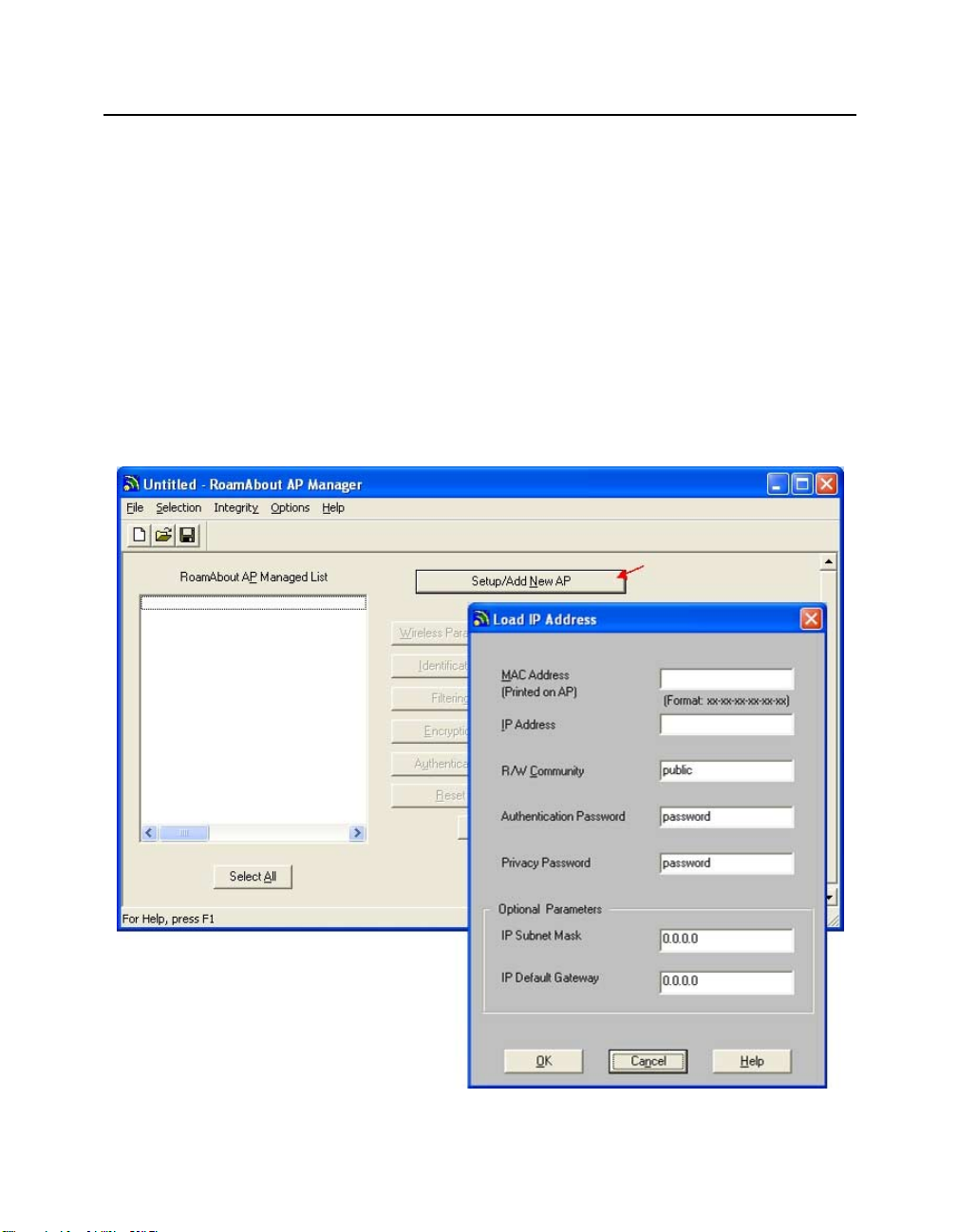
RoamAbout AP Manager
Installing the RoamAbout AP Manager
The AP Manager supports Windows 95, Wind ow s 98, Windows 2000, Windows Me,
Windows NT (V4.0 or later), and Windows XP.
The AP Manager can manage APs from a wireless computer. However, the AP Manager
needs to be on a computer connected to the s ame wired LAN as the AP to assign an IP
address or upgrade the AP firmware.
The AP Manager is included on the CD-ROM in the RoamAbout AP kit, and can also be
downloaded from the enterasys.com/wireless web site. To install the AP Manager, follow
the installation instructions. After the installation, you can open the AP Manager main
window, shown in Figure 4-1, by clicking the Start button on the Windows desktop and
selecting Programs
Figure 4-1: RoamAbout AP Manager Main Window
→RoamAbout→RoamAbout AP Manager.
4-3
Page 76

RoamAbout AP Manager
Using the AP Manager
You can manage APs individually or as a single group. You can group APs based on any
criteria, such as:
• All APs belonging to the same netwo rk are in one grou p. For exampl e, have one grou p
for the Accounting network and one group for the Engineering network.
• To avoid confusion, you should have different groups for APs in an infrastructure
network and APs in a LAN-to-LAN configuration. APs in these configurations are
managed differently.
• If you have earlier releases of the RoamAbout AP, you can group non-802.11
compliant APs together, separate from the 802.11 APs.
The AP Manager saves each group in a configuration file (*.CFG). When you create a
group, give the file a meaning ful nam e th at r epres ents t he gro up, su ch as C a mpu s f or AP s
used outside on a college campus, or Engineering if all the APs are used for the Engineering
wireless network.
When you open a configuration file, the APs in the group are displayed in the Managed List
field on the main window (see Figure 4-1). You can add or remove APs from the
configuration file. The following lists some of the actions you can perform from the AP
Manager main window:
• Each time you open the AP Manager, the RoamAbout AP Managed List field is
blank. You need to open a file by clicking File in the menu bar, selecting Open, and
choosing a configuration file . Al l th e APs in tha t gr oup are dis pl ayed in t he Man aged
List field.
4-4
• If there is a RoamAbout R2 in the list, you are prompted for a password. The password
is the password that you entered when you created the configuration file.
• To display the settings that the AP is currently using, select the AP in the Managed List
field and click the various buttons, such as Wireless Parameters, Network
Parameters, and Hardware. Click the Help button in each dialog box for a
descripti on of the dialo g box.
• To check the Signal-to-Noise Ratio (SNR) between the AP and another device in the
same wireless network, select Integrity in the menu bar and select Link Test.
• To discover all APs in your network, select Selection in the menu bar and Discover.
Chapter 5 contains the procedures to configure APs using the AP Manager.
Page 77

Other SNMP Management Tools
The AP supports the Simple Network Management P rotocol (SNMP) throu gh any standard
Network Management Station (NM S) that supports SNMP. The SNMP management
capability enables you to manage standard SNMP MIB characteristics, such as protocol
filtering and address filtering.
• To manage the AP with an NMS, you must first use the console port or AP Manager
to configure the AP with a valid IP address.
• The RoamAbout R2 supports SNMPv3. If your NMS does not support SNMPv3 and
you want to use SNMPv1 or SNMPv2c, use the RoamAbout R2 console to access the
community names. The RoamAbou t R2 Co mmu nity sc reen con tains fou r co mmun ity
names that allow SNMPv1 and SNMPv2c read-only and read-write access to an NMS.
The names are disabled by default with the exception of Commun ity Name #1, which
is set to public. If using SNMPv3, you should leave names 2 through 4 disabled.
• The following AP settings are only accessible from an NMS:
—RMON parameters
— Aging timer
RoamAbout Console Port
Other SNMP Management Tools
You can manage the AP by connecting a terminal or personal computer running terminal
emulation software to the console port. Signals from the console port conform to the
EIA-232D signaling stand ard at 960 0 baud only. The port appears as a data terminal
equipment (DTE) device. Typically, you do not need to use the consol e port if you u se the
AP Manager to manage the AP. However, the R2 SNMP community names are only
modifiable from the R2 console port.
Refer to Appendix B for the procedure to connect a device to the AP console port.
4-5
Page 78

Telnet
Telnet
You can manage the RoamAbout R2 through Telnet. However, you must first assign the
R2 an IP address.
Perform the following steps to access the R2 through Telnet:
1. Open a DOS Prompt.
2. Telnet to the IP Address that you assigned to the RoamAbout R2.
For example: telnet 10.0.0.00
You are prompted for a username and password. The default username is admin and
the default password is password. The Main Menu appears.
3. Ensure that your preferences are set to use the arrow keys.
Web Management
You can manage the RoamAbout R2 through your web browser. However, you must first
assign the R2 an IP address. Refer to Appendix B for the procedure to connect a device to
the AP console port.
The RoamAbout R2 web management runs on the following browsers:
4-6
• Netscape Communicator V4.5, V4.6, V4.7 and V6.0 (and later)
• Microsoft Internet Explorer V4.0 and V5.0 (and later)
You must set the browser proxy to Direct Internet Connection. Then enter the IP address
that you assigned to the RoamAbout R2 in the browser window. You are prompted for a
username a nd password. The default username is admin and the default password is
password.
Page 79

RoamAbout Client Utility
The RoamAbout Client Utility is a diagnostic tool for RoamAbout wireless networks. The
RoamAbout Client Utility is included on the RoamAbout 802.11 PC Card Drivers and
Utilities CD-ROM, or you can download it from the RoamAbout Wireless web site. Refer
to the RoamAbout 802.11 PC Card Drivers and Utilities Setup and Ins tall ati on Gui de for
setup and installation information.
Use the Client Utility to:
• Perform a radio Link Test with a single AP or computer. The Link Test mode allows
you to verify the communications quality of the RoamAbout PC Card in more detail.
It allows you to investigate the performance of the RoamAbout radio link between:
— Your computer and another wireless computer
— Your computer and the current AP
• Perform a Site Survey running the Site Monitor option. Use the Site Monitor mode to
display the communications quality of your computer with multiple APs in its vicinity.
The Site Monitor mode allows you to conduct a site survey to:
— Determine the overall wireless coverage of your LAN network.
— Determine or optimize placement of your APs, to provide seamless connectivity
to mobile stations.
RoamAbout Client Utility
For detailed information about each Client Utility window, consult the RoamAbout Client
Utility on-line help by clicking the Help button in each window.
4-7
Page 80

Page 81

Configuring the Wireless Network
This chapter provides the procedures to configure the wireless device parameters. Before
performing these procedu res, you need to ins tall the wireles s network too ls as descri bed in
Chapter 4.
• To install the drivers and utilities on the clients, refer to the RoamAbout 802.11 PC
Card Drivers and Utilities Setup and Installation Guide.
• If you are configuring a wireless infrastructure network, configure the APs first. Many
of the wireless client parameters are based on the AP settings.
• For infrastructure and ad-hoc networks, document the common settings for any clients
that join the network at a future date.
In This Chapter
Information in this chapter is presented as follows:
Topic Page
Configuring APs in an Infrastructure Network 5-3
Configuring APs in a Point-to-Point Network 5-8
Configuring the AP for Point-to-Multipoint 5-13
Viewing Current AP Settings 5-18
Modifying the IP Address 5-19
Setting the Cabletron Dis covery Protocol 5-21
Modifying Wireless Parameters 5-22
Configuring for Security 5-24
Configuring the Console Port for Security 5-28
Configuring the R2 for SNMPv1 or SNMPv2 5-29
Configuring the AP for Authentication 5-30
Configuring for Rapid Rekeying 5-36
Configuring for VLANs 5-40
Chapter 5
5-1
Page 82

In This Chapter
Topic Page
Setting Spanning Tree 5-43
Filtering Traffic by Protocols 5-44
Filtering Traffic by Addresses 5-46
Checking the Configuration on Multiple APs 5-47
Resetting the RoamAbout AP 5-48
Using the RoamAbout R2 Web Management 5-49
Configuring Clients 5-50
5-2
Page 83

Configuring APs in an Infrastructure Network
Configuring APs in an Infrastructure Network
After installing the AP, you can configure its network and wireless parameters using th e
AP Manager, the console port, or th e R2 Web Management. To confi gure the R oamAbout
R2 for management by an NMS using SNMPv2 or SNMPv1, see “Configuring the R2 for
SNMPv1 or SNMPv2” on page 5-29.
Required Information
When configuring an AP, have the following information available:
• If the AP has been configured with an IP address, you need to know that IP address. If
the AP has not been assigned an IP address, you need the following:
— The AP wired MAC address, which is printed on the front of the Access Point
2000 and on the side of the RoamAbout R2.
— Valid, unused IP address. Depending on your network configuration, you may
also need to provide the subnet mask and default gateway.
• The AP SNMP read/write community name (default is public). If you do not enter the
correct community name, you cannot modif y the AP or add it to an AP Manager group.
• For a RoamAbout R2, the SNMPv3 Authentication and Privacy Passwords (default for
both is password).
• Identification information, such as a unique name for the AP, its location, and the name
of the person responsible for the AP.
Wireless Parameters Used in an Infrastructure Network
If adding APs to an existing wireless network, write down the wireless parameter settings.
If creating a wireless infras tructure networ k, you can ente r the Channel, Wirel ess Networ k
Name, and Station Name, and use the default settings for the other parameters. The
following describes the settings used in an infrastructur e netwo rk:
• Slot 1/Slot 2: (RoamAbout R2 only): Select the slot to be configured.
• Channel: Set adjacent APs to different channels that are at least five channels apart if
possible. See Appendix A for channel information.
• Wireless network name: The wireless network name can be any alphanumeric string
(uppercase and lowercase) with a maximum of 32 characters. Spaces are allowed. The
name is case-sensitive. An example of a wireless network name is:
My RoamAbout NETWORK 2
5-3
Page 84

Configuring APs in an Infrastructure Network
• Station name: Select a unique name that helps identify the location of the AP. Each
AP should have a unique station name.
• Bridge Mode: Set to Workgroup.
• AP Density: See AP Density and Roaming on page 2-8 for more information.
• Transmit Rate: The default setting works well in most environments. See “Transmit
Rate” on page 2-5.
• RTS Threshold: The default setting works well in most environments. See
“RTS/CTS Protocol” on page 2-9.
• Remote RTS Threshold: The def ault setting works well in most environments. See
“RTS/CTS Pr otocol” on page 2-9 . This setting is only available on a RoamAbout R2
managed by the AP Manager.
• DTIM: In nearly all environments, you should not change the defaul t DTIM of 1. See
“802.11 Power Management” on page 2-11.
• Secure Access: Enable to prevent clients without the correct wireless network name
from connecting to this AP.
• Multicast Transmit Rate: Identifies the desired transmission speed for the broadcast
and multicast traffic as forwarded by the AP to the wireless LAN. You should use the
lowest speed that you want to support. If using applications that use multicast traffic
(for example, IGMP), you can increase this rate from the default of 2 Mbit/s Fixed.
5-4
• IntraBSS Relay:
— Enable: Allows wireless users associated with an AP to see and communicate
between each other. This is accomplished by taking a multicast packet from one
wireless user and rebroadcasting it so that all wireless users see it.
— Disable: Prevents communication between users associated with an AP. This
mode is intended for use in the ISP market where the ISP does not want separ a te
households to browse the Network Neighborhood and see other customers and
their hard drives.
• Medium Density Distribution: Enable it to have the AP distribute its AP Density
(low, medium, high, minicell, microcell) to the clients. This setting is not available
from the console ports.
• Load Balancing: Forces wireless clients to associate with APs that are least busy,
resulting in a more even distribution of client associations between APs. Load
balancing increases the network's overall throughput. Load balancing is enabled by
default. This setting is not available from the console ports.
Page 85

Configuring APs in an Infrastructure Network
Using the AP Manager
Use the Help button in the AP Manager for a description of any field.
1. If you are currently managing APs with the AP Manager, determine if the new AP
belongs to an existing group. Refer to “RoamAbout AP Manager” on page 4-2 for a
descripti on of configuration groups.
File
→Open (adds the AP to an existing group)
File
→New (starts a new group)
2. Click Setup/Add New AP.
3. If the AP has been assigned a n IP addr ess, click No whe n asked if y ou need to load an
IP address on the AP. If the AP does not have an IP address, click Yes.
4. Enter a new IP address or the AP’s existing IP address and other network parameters
as prompted.
You may need to wait a few minutes for the IP address to load. Afterwards, the AP
Manager displays the Ide ntification and Wireless Parameter dialog boxes .
5. Identification: Enter information that will help administrators identify the AP.
6. Wireless Parameters: Enter the wireless parameters for your wireless networ k. If
your wireless network requires additional settings, click the Advanced button.
7. Click OK.
8. To implement your changes:
R2 AP: Select Reset from the main window. Select Reset Slot x, where x is the slot
(1 or 2) you configured.
AP 2000: Select Reset from the main window. Select Reset with Current Settings.
Allow approximately one minute for the AP to reset and complete its self-test.
9. Repeat this procedure to add additional APs to this or other configuration groups.
10. When configuring wireless clients, enter the Wireless network name especially if
Secure Access is enabled.
Refer to the other sections in this chapter to configure features such as authentication,
encryption, and filters.
5-5
Page 86

Configuring APs in an Infrastructure Network
Using the RoamAbout R2 Console Por t
To use the console port, follow the instructions in “Connecting a Device to the Console
Port” in Appendix B. Use Help in the console screens for a description of any field.
1. Choose Network Configuration from the Main Menu and enter the following
parameters:
IP address: Enter the IP address you wish to assign to the AP.
Subnet mask: Enter the subnet mask you wish to assign to the AP.
Default gateway: Enter the IP address of the default gateway.
Spanning Tree: Set to Disable.
IP Address Mode: Set to Manual when configuring an AP for the first time. For more
information, see “Modifying the IP Address” on page 5-19.
Ethernet Speed: This sets the speed of the wired Ethernet connection. The default
setting, autonegotiate, works well in most environments.
GVRP: Set to Disabled unless you are configuring the AP to support VLANs, as
described in “Configuring for VLANs” on page 5-40.
CDP: This setting is Disabled by default in Workgroup mode. To change this setting,
refer to “Setting the Cabletron Discovery Protocol” on page 5-21.
2. Choose Save.
5-6
3. Choose Wireless Configuration from the Main Menu, then choose Set/Show
Wireless Configuration.
4. At the top of screen, select the radio slot (1 or 2) to configure.
5. Enter the wireless parameters.
6. Set the Reset Option to Reset Radio if necessary (default setting).
7. Choose Save.
8. To configure the RoamAbout clients, write down the Wireless Network Name,
especially if Secure Access is enabled.
Refer to the other sections in this chapter to configure features such as authentication,
encryption, and filters.
Page 87

Configuring APs in an Infrastructure Network
Using the Access Point 2000 Console Port
To use the console port, follow the instructions in “Connecting a Device to the Console
Port” in Appendix B. Use Help in the console screens for a description of any field.
1. Choose Set IP Address from the Installation Menu.
2. Enter the IP address, subnet mask, and default gateway.
3. Choose Module-Specific Options from the Installation Menu.
4. Choose Set Wireless Configuration. Enter the wireless parameter s for your wireles s
network.
5. Select Module-Specific Options from the Installation Menu and set the following
parameters:
Bridge Mode Options: Set to Workgroup.
Enable/Disable Default Rate Limiting: Set to Disabled to disable the 100 Kbit/sec
limitation on multicast traffic.
6. Optionally, you can enable console security as follows:
a) Choose E na ble/Disable Console Password from the Installation Menu. Enable
Console Password to prevent other users from using the console port to view or
modify settings.
b) Select Set SNMP Rea d/Write Community from the Installation Menu. Enter a
new community name (4 to 31 printable ASCII characters). Users must enter the
community name to access the menu.
7. To implement your changes, select Reset with Current Settings from the Installation
Menu. Allow approximately one minute for the AP to reset and complete its self-test.
8. When configuring wireless clients, enter the Wireless network name esp ecially if
Secure Access is enabled.
Refer to the other sections in this chapter to configure features such as authentication,
encryption, and filters.
5-7
Page 88

Configuring APs in a Point-to-Point Network
Configuring APs in a Point-to-Point Network
You can configure two APs to communicate with each other in a LAN-to-LAN
Point-to-Point configurat ion using the AP Manager or the cons ole p ort as desc ribed in the
following sections. To configure the RoamAbout R2 for management by an NMS using
SNMPv2 or SNMPv1, see “Configuring the R2 for SNMPv1 or SNMPv2” on page
5-29.
Required Information
When configuring an AP, have the following information available:
• If the AP has been configured with an IP address, you need to know that IP address. If
the AP has not been assigned an IP address, you need the following:
— The AP wired MAC address, which is printed on the front of the Access Point
2000 and on the side of the RoamAbout R2.
— Valid, unused IP address. Depending on your network configuration, you may
also need to provide the subnet mask and default gateway.
• The AP SNMP read/write community name (default is public). If you do not enter the
correct community name, you cannot modif y the AP or add it to an AP Manager group.
• For a RoamAbout R2, the SNMPv3 Authentication and Privacy Passwords (default for
both is password).
5-8
• Wireless MAC address of each AP. The wireless MAC address is NOT the same as the
wired MAC address printed on the AP. Perform one of the following to see the wireless
MAC address:
— AP Manager: Select each AP from the Managed Li st field and click the
Hardware button.
— Access Point 2000 console port: Show Current Settings from the Installation
Menu.
— R2 console port: Current Configuration from the Main Menu.
— Back of the PC Card used in the AP. The MAC addres s of the PC Card is the AP’s
wireless MAC address.
• Identification information, such as a unique name for the AP, its location, and the name
of the person responsible for the AP.
Page 89

Configuring APs in a Point-to-Point Network
Wireless Parameters Used in a Point-to-Poin t Network
The following AP parameters are not used in this configuration:
• Wireless Network Name
• Secure Access
• IntraBSS Relay
The following describes the settings used in a point-to-point network:
• Slot 1/Slot 2: (RoamAbout R2 only): Select the slot to be configured.
• Channel: Both APs must use the same channel.
• Station name: Select a unique name that helps identify the location of the AP. Each
AP should have a unique station name.
• Bridge Mode: Set to LAN-to-LAN Endpoint.
• Remote Wireless MAC Address: Enter the wireless MAC address of the remote AP.
• Transmit Rate: A fixed rate is recommended for most environments. See “Transmit
Rate” on page 2-5.
• RTS Threshold: The default setting works well in most environments. See
“RTS/CTS Protocol” on page 2-9.
• Spanning Tree: Set to Enabled or Disabled. For more information, see “Spanning
Tree Protocol” on page 2-22.
• AP Density
• Power Management (DTIM Period)
• Multicast Transmit Rate
5-9
Page 90

Configuring APs in a Point-to-Point Network
Using the AP Manager
Use the Help button in the AP Manager for a description of any field.
1. If you are currently managing APs with the AP Manager, determine if the new AP
belongs to an existing group. Refer to “RoamAbout AP Manager” on page 4-2 for a
descripti on of configuration groups.
File
→Open (adds the AP to an existing group)
File
→New (starts a new group)
2. Click Setup/Add New AP.
3. If the AP has been assigned a n IP addr ess, click No whe n asked if y ou need to load an
IP address on the AP. If the AP does not have an IP address, click Yes.
4. Enter a new IP address or the AP’s existing IP address and other network parameters
as prompted.
You may need to wait a few minutes for the IP address to load. Afterwards, the AP
Manager displays the Ide ntification and Wireless Parameter dialog boxes .
5. Identification: Enter information that will help administrators identify the AP.
6. Wireless Parameters: Enter the wireless parameters for your wireless network. Click
the Advanced button to view all wireless parameters.
5-10
7. Click OK.
8. To implement your changes:
R2 AP: Select Reset from the main window. If changin g the bridge mode, select Reset
with Current Settings. Otherwise, select Reset Slot x, where x is the slot (1 or 2) you
configured.
AP 2000: Select Reset from the main window. Select Reset with Current Settings.
Allow approximately one minute for the AP to reset and complete its self-test.
9. Repeat this procedure at the other AP.
Refer to the other sections in this chapter to configure features such as encryption and
filters.
Page 91

Configuring APs in a Point-to-Point Network
Using the RoamAbout R2 Console Por t
To use the console port, follow the instructions in “Connecting a Device to the Console
Port” in Appendix B. Use Help in the console screens for a description of any field.
1. Choose Network Configuration from the Main Menu and enter the following
parameters:
IP address: Enter the IP address you wish to assign to the AP.
Subnet mask: Enter the subnet mask you wish to assign to the AP.
Default gateway: Enter the IP address of the default gateway.
Spanning Tree: Set to Enabled or Disabled. For more information, see “Spanning
Tree Protocol” on page 2-22.
IP Address Mode: Set to Manual when configuring an AP for the first time. For more
information, see “Modifying the IP Address” on page 5-19.
Ethernet Speed: This sets the speed of the wired Ethernet connection. The default
setting, autonegotiate, works well in most environments.
GVRP: Set to Disabled unless you are configuring the AP to support VLANs, as
described in “Configuring for VLANs” on page 5-40.
CDP: This setting is Auto Enabled by default in LAN-to-LAN mode. To change this
setting, refer to “Setting the Cabletron Discovery Protocol” on page 5-21.
2. Choose Save.
3. Choose Wireless Configuration from the Main Menu, then choose Set/Show
Wireless Configuration.
4. At the top of screen, select the radio slot (1 or 2) to configure.
5. Enter the wireless parameters.
6. Set the Reset Option to Reset Radio if necessary (default setting).
7. Choose Save.
8. If changing the bridge mode, you need to implement your changes by choosing
Reset/Upgrade in the Main Menu then choosing Reset Switch. Allow approximately
one minute for the AP to reset and complete its self-test.
9. Perform this procedure on the other AP.
Refer to the other sections in this chapter to configure features such as encryption and
filters.
5-11
Page 92

Configuring APs in a Point-to-Point Network
Using the Access Point 2000 Console Port
To use the console port, follow the instructions in “Connecting a Device to the Console
Port” in Appendix B. Use Help in the console screens for a description of any field.
1. Choose Set IP Address from the Installation Menu.
2. Enter the IP address, subnet mask, and default gateway.
3. Choose Module-Specific Options from the Installation Menu.
4. Choose Set Wireless Configuration. Enter the parameters for your wireles s network.
5. Select Bridge Mode Options in the Module-Specific Options menu.
Bridge Mode: Set to LAN-to-LAN End-Point.
Remote Wireless MAC Address: Enter the wireless MAC address of the remote AP.
Spanning Tree Mode: Set to Enabled or Disabled. For more information, see
Spanning Tree Protocol on page 2-22.
6. Optionally, you can enable console security as follows:
a) From the Installation Menu, choose Enable/Disable Console Password. Set to
Enable.
b) Select Set SNMP Rea d/Write Community from the Installation Menu. Enter a
new community name (4 to 31 printable ASCII characters). Users must enter the
community name to access the menu.
5-12
7. To implement your changes, select Reset with Current Settings from the Installation
Menu. Allow approximately one minute for the AP to reset and complete its self-test.
8. Perform this procedure on the other AP.
Refer to the other sections in this chapter to configure features such as encryption and
filters.
Page 93

Configuring the AP for Point-to-Multipoint
Configuring the AP for Point-to-Multipoint
You can configure up to seven APs in a point-to-multipoint configuration. At least one AP
must be configured as a Central AP. The other APs are configured as endpoint APs, as
described in “Point-to-Multipoint” on page 1-10. To configure the RoamAbout R2 for
management by an NMS using SNMPv2 or SNMPv1, see “Configuring the R2 for
SNMPv1 or SNMPv2” on page 5-29.
Required Information
When configuring an AP, have the following information available:
• Valid Multipoint Activation Key (16 characters) to enable Multipoint bridge mode
(purchased separately). Contact your Enterasys Representative.
• If the AP has been configured with an IP address, you need to know that IP address. If
the AP has not been assigned an IP address, you need the following:
— The AP wired MAC address, which is printed on the front of the Access Point
2000 and on the side of the RoamAbout R2.
— Valid, unused IP address. Depending on your network configuration, you may
also need to provide the subnet mask and default gateway.
• The AP SNMP read/write community name (default is public). If you do not enter the
correct community name, you cannot modify the AP or add it to the AP Manager
group.
• For a RoamAbout R2, the SNMPv3 Authentication and Privacy Passwords (default for
both is password).
• Wireless MAC address of each AP. The wireless MAC address is NOT the same as the
wired MAC address printed on the AP. Perform one of the following to see the wireless
MAC address:
— AP Manager: Select each AP from the Managed Li st field and click the
Hardware button.
— Access Point 2000 console port: Show Current Settings from the Installation
Menu.
— R2 console port: Current Configuration from the Main Menu.
— Back of the PC Card used in the AP. The MAC addres s of the PC Card is the AP’s
wireless MAC address.
• Identification information, such as a unique name for the AP, its location, and the name
of the person responsible for the AP.
5-13
Page 94

Configuring the AP for Point-to-Multipoint
Wireless Parameters Used in a Point-to- Multipoint Network
The following AP parameters are not used in this configuration:
• Wireless Network Name
• Secure Access
• IntraBSS Relay
The following describes the settings used in a point-to-multipoint network:
• Slot 1/Slot 2 (RoamAbout R2 only): Select the slot to be configured. For the central
AP, Slot 1 must be selected.
• Channel. All APs must use the same channel.
• Station name. Select a unique name that helps identify the location of the AP. Each
AP should have a unique station name.
• Bridge Mode:
Central AP: Set to LAN-to-LAN Multipoint.
Endpoint APs: Set to LAN-to-LAN Endpoint.
• Multipoint Activation Key (Central AP only): Enter the 16 character alphanumeric
activation key.
• Remote Wireless MAC addresses: Central AP: Enter the wireles s MAC ad dresses of
the other APs. Any unused fields must be null (cont ain no characters ). Endpoi nt APs:
Enter the wireless MAC address of the Central AP.
• Wireless Relay (Central AP, Access Point 2000 only): Enable to allow the endpoint
APs to communicate with each other through the Central AP, or Disable to only allow
the endpoint APs to communicate with the Central AP and its wired LAN.
• AP Density
• Power Management (DTIM Period)
• Multicast Transmit Rate
5-14
• Transmit Rate: The default setting works well in most environments. See “Transmit
Rate” on page 2-5.
• RTS Threshold: The default setting works well in most environments. See
“RTS/CTS Protocol” on page 2-9.
• Spanning Tree: Central AP: Set to Enabled. Endpoint APs: Enable or disable. For
more information, see “Spanning Tree Protocol” on page 2-22.
Page 95

Configuring the AP for Point-to-Multipoint
Using the AP Manager
Use the Help button in the AP Manager for a description of any field.
1. Determine which AP is the Central AP, as described in “Point-to-Multipoint” on
page 1-10.
2. If you are currently managing APs with the AP Manager, determine if the new AP
belongs to an existing group. Refer to “RoamAbout AP Manager” on page 4-2 for a
descripti on of configuration groups.
→Open (adds the AP to an existing group)
File
File
→New (starts a new group)
3. Click Setup/Add New AP.
4. If the AP has been assigned a n IP addr ess, click No whe n asked if y ou need to load an
IP address on the AP. If the AP does not have an IP address, click Yes.
5. Enter a new IP address or the AP’s existing IP address and other network parameters
as prompted.
You may need to wait a few minutes for the IP address to load. Afterwards, the AP
Manager displays the Ide ntification and Wireless Parameter dialog boxes .
6. Identification: Enter information that will help administrators identify the AP.
7. Wireless Parameters: Enter the wireless parameters for your wireless network. Click
the Advanced button to view all the wireless parameters.
When configuring the Central AP, click the LAN-to-LAN Multipoint Properties
button to enter the w irel ess MAC addresses of the other APs. Any unused f ields must
be null (contain no characters).
8. Click OK.
9. To implement your changes:
R2 AP: Select Reset from the main window. If changin g the bridge mode, select Reset
with Current Settings. Otherwise, select Reset Slot x, where x is the slot (1 or 2) you
configured.
AP 2000: Select Reset from the main window. Select Reset with Current Settings.
Allow approximately one minute for the AP to reset and complete its self-test.
10. Repeat this procedure at the other APs.
Refer to the other sections in this chapter to configure features such as encryption and
filters.
5-15
Page 96

Configuring the AP for Point-to-Multipoint
Using the RoamAbout R2 Console Por t
To use the console port, follow the instructions in “Connecting a Device to the Console
Port” in Appendix B. Use Help in the console screens for a description of any field.
1. Choose Network Configuration from the Main Menu and enter the following:
IP address: Enter the IP address you wish to assign to the AP.
Subnet mask: Enter the subnet mask you wish to assign to the AP.
Default gateway: Enter the IP address of the default gateway.
Spanning Tree: For the Central AP, set to Enabled. For the APs in LAN-to-LAN
Endpoint bridge mode, you can enable or disable Spanning Tree. For more
information, see “Spanning Tree Protocol” on page 2-22.
IP Address Mode: Set to Manual when configuring an AP for the first time. For more
information, see “Modifying the IP Address” on page 5-19.
Ethernet Speed: This sets the speed of the wired Ethernet connection. The default
setting, autonegotiate, works well in most environments.
GVRP: Set to Disabled unless you are configuring the AP to support VLANs, as
described in “Configuring for VLANs” on page 5-40.
CDP: This setting is Auto Enabled by default in LAN-to-LAN mode. To change this
setting, refer to “Setting the Cabletron Discovery Protocol” on page 5-21.
5-16
2. Choose Save.
3. Choose Wireless Configuration from the Main Menu, then choose Set/Show
Wireless Configuration.
4. At the top of screen, select the radio slot (1 or 2) to configure.
5. Enter the wireless parameters.
6. Set the Reset Option to Reset Radio if necessary (default setting).
7. Choose Save.
8. If changing the bridge mode, you need to implement your changes by choosing
Reset/Upgrade in the Main Menu then choosing Reset Switch. Allow approximately
one minute for the AP to reset and complete its self-test.
Refer to the other sections in this chapter to configure features such as encryption and
filters.
Page 97

Configuring the AP for Point-to-Multipoint
Using the Access Point 2000 Console Port
To use the console port, follow the instructions in “Connecting a Device to the Console
Port” in Appendix B. Use Help in the console screens for a description of any field.
1. Choose Set IP Address from the Installation Menu.
2. Enter the IP address, subnet mask, and default gateway.
3. Choose Module-Specific Options from the Installation Menu.
4. Choose Set Wireless Configuration. Enter the wireless parameter s for your wireles s
network.
5. Select Bridge Mode Options from the Module-Specific Options menu and continue
entering the wireless parameters.
6. Optionally, you can enable console security as follows:
a) From the Installation Menu, choose Enable/Disable Console Password. Set to
Enable.
b) Select Set SNMP Rea d/Write Community from the Installation Menu. Enter a
new community name (4 to 31 printable ASCII characters). Users must enter the
community name to access the menu.
7. To implement your changes, reset the AP by selecting Reset with Current Settings
from the Installation Menu. Allow approximately one minute for the AP to reset and
complete its self-test.
8. Perform this procedure on the other APs.
Refer to the other sections in this chapter to configure features such as authentication and
filters.
5-17
Page 98

Viewing Current AP Settings
Viewing Current AP Settings
You can view the current settings before you modify the RoamAbout AP parameters.
Using the AP Manager
Using the AP Manager, select the AP from the Managed List field and click the various
buttons, such as Wireless Parameters, Network Parameters, and Hardware. In the
Wireless Parameters dialog box, click the Advanced button to view all the wireless
parameters. If you have changed any wireless parameters and have not yet reset the AP,
both the operating (current) settings and the settings that take affect after the next reset are
displayed.
Using the RoamAbout R2 Console
• Choose Current Configuration from the Main Menu to view the network and
hardware parameters.
• To display the current wireless settings, choose Wireless Configuration in the Main
Menu, then choose Set/Show Wireless Configuration. If you have changed a wirele ss
parameter but not yet reset the AP, the new setting is NOT reflected in this display .
Using the Access Point 2000 Console
• Choose Show Current Settings from the Installation Menu to view the network and
hardware parameters.
5-18
• To display the current wireless settings, choose Module-Specific Options then select
Show Wireless Configuration. If you have changed a wirele ss parameter but not yet
reset the AP, the new setting is NOT reflected in this display.
Page 99

Modifying the IP Address
The AP can obtain an IP address using these methods:
• BootP (default): The AP obtains its IP Address from a BootP server when it reboots.
A BootP server must be co nfi gu red i n ad vance t o r esp ond w ith the desired IP address.
• DHCP: The AP obtains its IP address from a DHCP server. This option is not
recommended for enterprise networks.
• Manual: Prevents the AP from issuing BootP or DHCP requests to obtain an IP
address. Use this setting if the AP was already assigned an IP address and you do not
want to change it.
Using the AP Manager
You can use the AP Manager to chan ge the IP addr ess using a BootP o r DHCP server. You
also have the option to manually change the IP addres s of an Access Po int or Access Point
2000. To only modify the subn et mask or default gateway, select the AP from the Managed
List field and click the Network Parameters button. A reset is not needed.
To change the AP’s current IP address using BootP or DHCP, perform the following:
1. Select the AP from the Managed List field.
Modifying the IP Address
2. Click the Network Parameters button and set the following parameters:
Address State: Set to Volatile. The address state options are inactive if this parameter
was disabled using the console port. This setting i s not used on a RoamAbout R2.
IP Address Initialization: Set to DHCP o r BootP to automatically assign an IP
Address to the AP after the reset.
3. Click OK.
4. In the AP Manager main window, click the Reset button. Then click Reset with
Current Settings. The AP is reset and uses the selected method to obtain an IP
address.
When done, you may need to delete the AP with the old IP address from the managed list.
To manage the AP with the new IP address with AP Manager, use the Setup/Add New AP
button from the main window or use Selection
→Discover from the menu bar.
5-19
Page 100

Modifying the IP Address
To manually change the IP address of an Access Point or Access Point 2000, perform the
following. You will need the AP’s wired MAC address and an unused IP address.
1. Select the AP in the managed list.
2. Click on the Network Parameters button.
3. Set the Address State to Volatile.
4. Select Manual from the IP Address Initialization option.
5. Click OK.
6. In the main AP Manager window, click the Reset button. Then, click Reset with
Current Settings.
7. Click the Setup/Add New AP button from the main window.
8. Click Yes in the Load IP Address message.
9. In the Load IP Address dialog, enter the wired MAC address, new IP Address, and
other parameters as necessary.
10. Click OK.
11. If a message appears about reloading an R2, click OK to close the message and
continue loading the new address.
Using the RoamAbout R2 Console Por t
1. Choose Network Configuration from the Main Menu and enter the following
parameters:
IP address: If manually entering an IP address, enter the IP address you wish to assign
to the AP.
Subnet mask: Enter the subnet mask you wish to assign to the AP.
Default gateway: Enter the IP address of the default gateway.
IP Address Mode: Set to Manual, DHCP, or BootP. The AP uses this method to obtain
an IP address on the next reset.
2. Choose Save. You do not need to reset the AP.
5-20
 Loading...