

Page 1

SmartSwitch 6000 and
Matrix E7 Modules
User’s Guide
Page 2

Page 3

Notice
Enterasys reserves the right to make changes in specifications and other information contained in this document
without prior notice. The reader should in all cases consult Enterasys to determine whether any such changes
have been m ade.
The hardware, firmware, or software described in this manual is subject to chang e without notice.
IN NO EVENT SHALL ENTERASYS BE LIABLE FOR ANY INCIDENTAL, INDIRECT, SPECIAL, OR
CONSEQUENTIAL DAMAGES WHATSOEVER (INCLUDING BUT NOT LIMITED TO LOST PROFITS)
ARISING OUT OF OR RELATED TO THIS MANUAL OR THE INFORMATION CONTAINED IN IT,
EVEN IF ENTERASYS HAS BEEN ADVISED OF, KNOWN, OR SHOULD HAVE KNOWN, THE
POSSIBILITY OF SUCH DAMAGES.
Virus Disclaimer
Enterasys has tested its software with current virus checking technologies. However, because no anti-virus
system is 100% reliable, we strongly caution you to write protect and then verify that the Licensed Software,
prior to installing it, is virus-free with an anti-virus system in which you have confidence.
Enterasys makes no representations or warranties to the effect that the Licensed Software is virus-free.
Copyright 2000, 2001 by Enterasys, Inc. All rights reserved.
Printed in the United States of America.
Order Number: 9033404-02
Enterasys, Inc.
P.O. Box 5005
Rochester, NH 03866-5005
Enterasys, NetSight and Matrix E7 are trademarks of Enterasys. MiniMMAC, FNB, Multi Media Access
Center, and DNI are registered trademarks, and Portable Management Application, IRM, IRM2, IRM3,
IRBM, ETSMIM, EFDMIM, EMME, ETWMIM, FDMMIM, FDCMIM, MRXI, MRXI-24, NB20E,
NB25E, NB30, NB35E, SEHI, TRBMIM, TRMM, TRMMIM, TRXI, Media Interface Module, MIM, and
Flexible Network Bus are trademarks of Cabletron, Inc.
UNIX and OPENLOOK is a trademark of Unix System Laboratories, Inc. OSF/Motif and Motif are
trademarks of the Open Software Foundation, Inc. X Window System is a trademark of Massachusetts Institute
of Technology. Ethernet and XNS are trademarks of Xerox Corporation. Apple and AppleTalk are registered
trademarks of Apple Computer, Inc. Banyan is a registered trademark of Banyan Systems, Inc. DECnet is a
registered trademark of Digital Equipment Corporation. Novell is a registered trademark of Novell, Inc.
CompuServe is a registered trademark of CompuServe. Sun Microsystems is a registered trademark, and Sun,
SunNet, and OpenWindows are trademarks of Sun Microsystems, Inc.
i
Page 4

Restricted Rights Notice
(Applicable to licenses to the United States Government only.)
1. Use, duplication, or disclosure by the Government is subject to restrictions as set forth in subparagraph (c)
(1) (ii) of the Rights in Technical Data and Computer Software clause at DFARS 252.227-7013.
Enterasys, Inc., 35 Industrial Way, Rochester, New Hampshire 03867-0505.
2. (a) This computer software is submitted with restricted rights. It may not be used, reproduced, or disclosed
by the Government except as provided in parag raph (b) of this Notice or as o therwise expressly stated in
the contract.
(b) This computer software may be:
(1) Used or copied for use in or with the computer or computer s for which it was acquired, including
use at any Government installation to which such computer or computers may be transferred;
(2) Used or copied for use in a backup computer if any computer for which it was acquired is
inoperative;
(3) Reproduced for safekeeping (archives) or backup purposes;
(4) Modified, adapted, or combined with other computer software, provided that the modified,
combined, or adapted portions of the derivative software incorporating restricted computer
software are made subject to the same restricted rights;
(5) Disclosed to and reproduced for use by support service contractors in accordance with
subparagraphs (b) (1) through (4) of this claus e, pro vided the Gov ernment m akes s uch disclos ure
or reproduction subject to these restricted rights; and
(6) Used or copied for use in or transferred to a replacement computer.
(c) Notwithstanding the foregoing, if t his computer softwar e is publ ished copyr ighted computer s oftware, it
is licensed to the Government, without disclosure prohibitions, with the minimum rights set forth in
paragraph (b) of this clause.
(d) Any other rights or limitation s regarding the use, d uplication, or d isclosure of t his computer s oftware are
to be expressly stated in, or incorporated in, the contract.
(e) This Notice shall be marked on any reproduction of this computer software, in whole or in part.
ii
Page 5

iii
Page 6

Chapter 1 Introduction
Using the SmartSwitch 6000 and Matrix E7 User’s Guide.............................................1-5
Related Manuals ..............................................................................................................1-7
Getting Help.....................................................................................................................1-7
Using On-line Help................................................................................................... 1-7
Accessing On-line Documentation........................................................................... 1-8
Documentation Feedback.................................................................................. 1-8
Getting Technical Support........................................................................................1-8
Online Services on the Wor ld Wide Web..........................................................1-8
Global Technical Assistance Center..................................................................1-8
Chapter 2 The Device View
Viewing Devi ce Inform ation .................. ...... ............................................. ...... ................ 2-2
General Device Information.....................................................................................2-4
6C105/6C107 Chassis-specific Information.............................................................2-5
Menu Structure.........................................................................................................2-7
Port Status Displays.................... ..... ............................................. ..........................2-14
Selecting a Port Status View............................................................................2-14
Port Status Color Codes..................................................................... ..... ......... 2-19
The Chassis Backplane View.................................................................................. 2-20
The Chassis Backplane View .......................................................................... 2-20
The Chassis Manager Window...............................................................................2-23
The Module Information Window.......................................................................... 2-24
Viewing Har dware Types ...................... ...... ..... ............................................. ...... ...2-25
Device Type.....................................................................................................2-26
Module Type.................................................................................................... 2-26
Interface Description.......................................................................................2-26
Viewing I/F Summary Information ........................................................................ 2-27
Interface Performance Statistics...................................................................... 2-28
Viewing Interface Detail..................................................................................2-30
Using the Device Find Source Address Option......................................................2-32
Using Device Find Source Address on Ethernet MicroLAN Modules........... 2-34
Managing the Module............................. ...... ............................................. ...... .............. 2-36
Configuring Ports ...................................................................................................2-36
Configuring Standard Ethernet and FDDI Ports ............................................. 2-37
Configuring Fast Ethernet Ports on First Generation Modules.......................2-39
Configuring Ethernet Ports on Second Generation Modules .......................... 2-44
Configuring the COM Port..............................................................................2-49
Contents
iv
Page 7

Contents
Using an Uninterruptable Power Supply (UPS).....................................................2-51
Accessing the UPS Window............................................................................2-51
Setting the UPS ID ..........................................................................................2-53
Using the Test Option......................................................................................2-53
Using the Disconnect Option...........................................................................2-54
Redirecting Traffic..................................................................................................2-54
Priority Configuration.............................................................................................2-56
Configuring Priority Queuing Based on Receive Port ....................................2-58
Configuring Priority Queuing Based on MAC-layer Information ..................2-59
Configuring Priority Queuing Based on Packet Type.....................................2-62
Broadcast Suppression............................................................................................2-64
The System Resources Window .............................................................................2-66
Reserving CPU Bandwidth...................................................... ........................2-69
802.1Q VLANs.......................................................................................................2-70
What is a VLAN? ............................................................................................2-70
What is an 802.1Q Port-Based VLAN?...........................................................2-70
About 802.1Q VLAN Configuration and Operation.......................................2-70
Configuring Your 802.1Q VLANS.........................................................................2-72
Setting VLAN Parameters and Operational Modes ........................................2-73
Performing Ingress List Configuration............................................................2-75
Performing Egress List Configuration.............................................................2-78
VLAN and Priority Configuration..........................................................................2-81
Configuring Bridge and Bridge Port Capability..............................................2-81
Setting VLAN Parameters and Operational Modes ........................................2-84
Configuring Basic VLAN Port Parameters.....................................................2-87
Configuring Advanced VLAN Port Parameters..............................................2-89
Performing Egress List Configuration.............................................................2-93
Setting Port Priority.........................................................................................2-96
Setting Port Priority-to-Traffic Class Mapping...............................................2-97
Setting GARP Times .......................................................................................2-99
Configuring GMRP Status.............................................................................2-101
Clicking the Refresh button will update the information displayed in the Port GMRP
table without closing the window..................................................................2-103
Setting the Device Date and Time........................................................................2-103
Enabling and Disabling Ports ...............................................................................2-104
Chapter 3 Statistics
Accessing the Statistics Windows....................................................................................3-1
RMON Statistics..............................................................................................................3-2
Viewing Total, Delta, and Accumulated Statistics....................................................3-5
Printing Statistics......................................................................................................3-6
Interface Statistics............................................................................................................3-7
Making Sense of Interface Statistics.........................................................................3-9
v
Page 8

Chapter 4 Alarm Configuration
About RMON Alarms and Events................................................................................... 4-1
Basic Alarm Configuration..............................................................................................4-2
Accessing the Basic Alarm Configuration Window.................................................4-3
Viewing Alarm Status........................................................................................ 4-3
Creating and Editing a Basic Alarm.........................................................................4-6
Disabling a Basic Alarm...........................................................................................4-9
Viewing the Basic Alarm Log ..................................................................................4-9
Advanced Alarm Configuration..................................................................................... 4-11
Accessing the RMON Advanced Alarm/Event List...............................................4-11
Creating and Editing an Advanced Alarm..............................................................4-14
Creating and Editing an Event................................................................................4-21
Adding Actions to an Event............................................................................4-24
Deleting an Alarm, Event, or Action............................................ ...... ....................4-26
Viewing an Advanced Alarm Event Log................................................................4-27
How Rising and Falling Thresholds Work..................................................................... 4-27
Chapter 5 Managing Ethernet MicroLAN Modules
Contents
Repeater Statistics............................................................................................................ 5-1
The Statistics Windows ............................................................................................5-2
Accessing the Statistics Windows.....................................................................5-2
Statistics Defined...............................................................................................5-3
Using the Total and Delta Option Buttons ........................................................5-5
Timer Statistics .........................................................................................................5-6
Accessing the Timer Statistics Windows...........................................................5-6
Setting the Timer Statistics Interval ..................................................................5-8
Repeater Performance Graphs.................................................................................. 5-8
Accessing the Performance Graph Windows....................................................5-9
Configuring the Performance Graphs.............................................................. 5-12
The Detail Button............................................................................................5-12
Using Port Locking and Unlocking........................................................................ 5-13
Viewing Lock Status Information ......................................... ...... ...... .............. 5-14
Determining a Port’s Topology Status............................................................. 5-15
Locking and Unlocking all Ports on a Repeater Channel................................5-15
Locking and Unlocking Individual Ports........................................................5-17
Alarm Limits..................... ............................................. ............................................. ...5-17
Accessing the Alarm Limits Windows...................................................................5-18
Configuring Alarms................................................................................................5-22
Setting the Alarm Limits Time Interval .......................................................... 5-22
Setting Alarm Limits ..............................................................................................5-23
Trap Selection................................................................................................................5-24
Accessing the Trap Selection Windows .................................................................5-24
Trap Definitions...................................................................................................... 5-26
Configuring Traps...................................................................................................5-27
vi
Page 9

Contents
Chapter 6 FDDI Management
Viewing FDDI Information............................ ...... ............................................. ...... ..... ....6-1
Configuration............................... ...... ..... ...... ...... ............................................. ..... ....6-3
Connection Policy.....................................................................................................6-6
Station List................................................................................................................6-9
Stations Panel...................................................................................................6-10
Performance............................................................................................................6-11
FDDI Statistics........................................................................................................6-12
Setting the FDDI Statistics Poll Rate...............................................................6-14
Configuring FDDI Frame Translation Settings..............................................................6-14
Information about Ethernet and FDDI Frame Types..............................................6-15
Ethernet Frames...............................................................................................6-16
FDDI Frames...................................................................................................6-17
FDDI Frame Translation Options ...........................................................................6-18
Chapter 7 ATM Configuration
Accessing the ATM Connections Window ......................................................................7-1
Configuring Connections.................................................................................................7-4
Adding a New Connection........................................................................................7-4
Deleting a Connection ............................................. ...... ...... .....................................7-4
Chapter 8 HSIM-W87 Configuration
The T3 Configuration Window........................................................................................8-1
The T1 Configuration Window........................................................................................8-3
Configuring IP Priority....................................................................................................8-6
Index
vii
Page 10

Chapter 1
Introduction
About the SmartSwitch 6000 and Matrix E7 families; how to use this guide; related guides; getting
help.
Welcome to the Element Manager for the SmartSwitch 6000 and Matrix E7 Modules
User’s Guide. This guide is a reference for using NetSight Element Manager for the
SmartSwitch 6000 and Matrix E7 products. The SmartSwitch 6000 and Matrix E7
products encompass the 6C105 chassis (for the 6000) and 6C107 chassis (for the Matrix
E7), as well as the SmartSwitch 6000 and Matrix E7 series modules.
The 6C105 SmartSwitch chassis is a stand-alone chassis. It offers five slots for interface
modules; it also has two slots for dual redundant power supplies (installed vertically to the
right of the module slots), and a removable fan tray (installed horizontally across the
bottom the chassis).
NOTE
The 6C107 Matrix E7 chassis is also a stand-alone chassis. It offers seven slots for
interface modules; it has a removable fan tray (installed underneath the module slots); it
also has two slots for dual redundant power supplies (installed across the bottom of the
chassis).
For Matrix E7 users: Modules for the Matr ix E7 (6C107) chassis are third generation
(6x3xx) boards. Third generation boards are fully supported in any of the 6C107 chassis’
seven slots. Second generation boards (6x2xx SmartSwitch modules) are fully supported
in slots 1-5 in the 6C107 chassis. A second generation board in slot 6 or 7 of the 6C107
will act as a standalone module.
The SmartSwitch 6000 Frame Transfer Matrix (FTM) backplane and Matrix E7 nTERA
backplane provide distributed processing po wer. The backplane’s passive design provides
a separate independent backplane connection from each module in the chassis to every
other module installed in the chassis; each module contains its own active switching
components (so switching horsepower increases with module density), and each module
can be managed independently (via its Module Manager management component) or —
for devices which support distributed management — as part of the chassis unit.
1-1
Page 11

Introduction
The SmartSwitch 6000 and Matrix E7 modules include:
•The 6E122-26 and 6E123-26 SmartSwitch modules each provide 24 fixed 10Base-T
switch ports (via RJ45 connect ors on the 6 E122; RJ21 T elco connectors on t he 6E123)
and two slots for optional FE-100xx Fast Ethernet Port Interface Modules (FEPIMs).
Several Fast Ethernet port modules are available:
- the FE-100FX, which provides one multi-mode fiber port via an SC connector;
- the FE-100TX, with one Category 5 UTP RJ45 connector;
- the FE-100F3, with one single-mode fiber port via an SC connector;
- and the FE-100S1, S3, and S5, which prov ide one mult i-mode fib er , singl e-mode
fiber, or long reach single-mode fiber SONET/SDH port, all via SC connectors.
•The 6E132-25 and 6E133-25 SmartSwitch modules each provide 24 fixed 10Base-T
switch ports (also via R J45 fo r the 6E 132 and RJ2 1 for t he 6E133 ) and one s lot for an
optional High Speed Interface Module (HSIM) that can link the chassis to an FDDI,
ATM, WAN, or Gigabit Ethernet backbone. Each HSIM provides frame translation
between ATM, FDDI, WAN, Gigabit Ethernet, and Ethernet through an on-board Intel
i960 processor:
- The HSIM-F6 is an FDDI/Ethernet Translator , which can act as a Single Attached
Station (SAS) or Dual Attached Station (DAS) on an external FDDI ring.
Enterasys’ FDDI Port Interface Modules ( FPIMs) pro vide a wide rang e of med ia
connectivity to the ring. The HSIM-F6 also has full-duplex capability, allowing
for a 200 Mbps connection to another HSIM-F6.
- The HSIM-A6DP is an Asynchronous Transfer Mode (ATM) HSIM, which
provides an ATM uplink via two media-configurable ATM Port Interface
Modules (APIMs). The dual APIM design allows for a redundant connection to
the uplink, so that if the primary interface fails, the secondary interface will
automatically take over. The HSIM-A6DP acts as an ATM Forum LAN
Emulation Client (LEC) so that it can transfer data between devices on an 802.x
LAN supported by the SmartSwitch 6000 and Matrix E7 and ATM-connected end
stations across a high speed ATM Link. The HSIM-A6DP adheres to the ATM
Forum-approved LAN Emulation (LANE) standard, which defines how end users
that rely on existing data communications technology and protocols can operate
over an ATM network without penalty.
- The HSIM-W6 and HSIM-W84 are Wide Area Networking (WAN) HSIMs,
which can provide uplinks to WAN backbones and allow you to perform seamless
LAN to WAN switching. The HSIM-W6 support s IP and IPX bridg ing or rout ing
services, including IP RIP. Multiple WAN connectivity options are supported,
including Sync, T1, E1, D&I, ISDN S/T , DDS, and HDSL interfaces, through the
use of two configurable WAN Physical Interface Modules (WPIMs).
Connectivity is available for Point to Point Protocol (PPP), as well as Frame Relay
and Leased Lines. Each WPIM can act independently, allowing simultaneous
communication, or configured to provide redundant channels if desired. The
HSIM-W84 provides a fixed configuration of four RJ45 ports for four active T1
interfaces.
1-2
Page 12

NOTE
Introduction
The HSIM-W6 and HSIM-W84 are intelligent devices that are functionally identical to the
CSX400. These HSIMs require their own IP addresses, and are managed as individual
devices rather than as part of the device in which they ar e installed. R efer to the CSX200
and CSX400 User’s Guide for details on managing these devices using NetSight Element
Manager.
- The HSIM-W87 is a Wide Area Network (WAN) HSIM that provides LAN to
WAN connectivity for any SmartSwitch that supports high-speed interface
modules (HSIMs). The HSIM-W87 has a DS3 interface (T3), providing up to 28
separate DS1 connections (T1). Refer to Chapter 8, HSIM-W87 Configuration,
for information on configuring an HSIM-W87.
- The HSIM-G01 and HSIM-G09 are Gigabit Ethernet HSIMs, each of which
provide a single Gigabit Ethernet connection that fully conforms to the IEEE
P802.3z (D3.1) Draft Standard. The HSIM-G01 provides a single 1000Base-SX
(short-wave) multimode fiber optic SC interface, allowing for link distances of up
to 500 meters. The HSIM-G09 provides a single 1000Base-LX (long-wave)
single mode/multimode fiber optic SC interface, allowing for link distances of up
to 3 kilometers.
- The HSIM-SSA710/20 are Wide Area Networking (WAN) HSIMs that support
up to two ISDN PRI interfaces with up to 24 V.90 56K modem connections.
The HSIM-SSA710/20 are intelligent devices that are managed as individual
devices rather than as part of the device in which they are installed. Before you
can access the device, you must add it to your central node database by inserting
it in an existing List, Tr ee, or Map View, or by doing a Discover p rocess (r efer to
your User’s Guide for more information). Once it has been added to your List,
Tree, or Map view, you can access and manage the HSIM according to the
information in Chapter 2, The Device View.
•The 6E128-26 and 6E129-26 SmartSwitch modules each provide 24 fixed Ethernet
fiber ports (multi-mode fiber on the 6E128; single-mode fiber on the 6E129) via ST
connectors, plus two slots for FEPIMs.
•The 6E138-25 and 6E139-25 SmartSwitch modules each provide 24 fixed Ethernet
fiber ports (multi-mode fiber on the 6E138; single-mode fiber for the 6E139) via ST
connectors, plus a single slot for an HSIM.
•The 6E123-50 and 6E133-49 SmartSwitch modules are 48 port MicroLAN Ethernet
modules (4 MicroLANs of 12 ports each, via four RJ21 Telco connectors). The
6E123-50 provides tw o FEPIM slots, wh ile the 6E133-4 9 provides a s ingle HSIM slot.
•The 6E233-49 SmartSwitch module provides 48 Ethernet ports via four RJ21
interfaces and one HSIM slot which can accept an y of the p revio usly detailed HSIMs.
•The 6G306-06 is a third-generation Matrix E7 and SmartSwitch 6000 module which
provides six Gigabit Ethernet ports via flexible GPIM uplin k m odules.
1-3
Page 13

Introduction
•The 6H123-50 SmartSwitch module is a 48 port MicroLAN 10/100 Mbps Ethernet
module (4 separately repeated MicroLANs of 12 ports each, via four RJ21 Telco
connectors). The 6H123-50 also provides two FEPIM slots for uplinks.
•The 6H133-37 SmartSwitch module is a 36 port MicroLAN 10/100 Mbps Ethernet
module (3 separately repeated MicroLANs of 12 ports each, via RJ21 Telco
connectors). A single HSIM slot is also provided.
•The 6H122-08, 6H128-08, and 6H129-08 SmartSwitch modules each provide six
fixed Fast Ethernet ports (via RJ45 on the 6H122, multi-mode fiber on the 6H128, and
single-mode fiber on the 6H129), plus two slots for FEPIMs.
•The 6H122-16 SmartSwitch module provides 16 fixed Fast Ethernet ports via RJ45
connectors, with no additional slots.
•The 6H202-24 and 6H252-17 SmartSwitch modules are 10/100 Fast Ethernet
modules. The 6H202-24 provides 24 ports via RJ45 connections. The 6H252-17
provides 16 ports via RJ45 connections as well as a VHSIM slot, which can accept any
of the previously detailed HSIMs or the VHSIM-G6 Gigabit Ethernet High Speed
Interface Module:
- The VHSIM-G6 is a Gigabit Ethernet module which provides two slots for
GPIMs of various media to offer integrated Gigabit Ethernet uplink capability.
The VHSIM-G6 can accept the GPIM-01, which offers one SC connector for
MMF 1000Base SX Gigabit Ethernet connectivity, the GPIM-09, which offers
one SC connector for MMF or SMF 1000Base LX connectivity , or the GPIM-04,
which offers one ANSI Fibrechannel style-2 connector for 150 Ohm STP
1000Base CX connectivity.
•The 6H203-24 and 6H253-13 SmartSwitch modules are 10/100 Fast Ethernet
modules. The 6H203-24 provides 24 ports via dual RJ21 connectors. The 6H253-13
provides 12 10/100 Fast Ethernet ports via a single RJ21 connector and also features a
VHSIM slot.
•The 6H258-17 and 6H259-17 SmartSwitch modules are 16-port 100BaseFX (via
MT-RJ connectors) modules, each with a single VHSIM slot. The 6H258-17 features
16 MMF ports, while the 6H259-17 features 16 SMF ports.
•The 6H262-18 SmartSwitch module provides 16 10/100BaseTX ports (via RJ45
connectors) plus two GPIM slots for Gigabit Ethernet connectivity.
•The 6H302-48 and 6H303-48 are third-generation 10/100 Fast Ethernet modules for
the SmartSwitch 60 00 and Mat rix E7 chass is, pr oviding 4 8 10/100 Fast Ether net ports
via RJ45 (6H302-48) and RJ21 (6H303-48) interfaces.
•The 6H308-24 and 6H308-48 high-density switching modules are Enterasys'
third-generation 100Base-FX switching solutions for the SmartSwitch 6000 and
Matrix E7. The addition of 100Base-FX technology allows cu stomers the ability to
securely depl oy fiber solutions to the de sktop.
•The 6H352-25 is a third generation 10/ 100 Gigabit Ether net switching so lution for t he
SmartSwitch 6000 and Matrix E7which delivers pinpoint control to critical network
entry areas, without the expense and com plexity of routed solutions.
1-4
Page 14

Introduction
•The 6M146-04 SmartSwitch carrier modul e provides t wo FEPIM slots an d two HSIM
slots.
Each of these SmartSwitch modules provide key mission-critical features such as
redundant links for load sharing, alarm thresholding, broadcast storm control, port
redirecting for traffic analysis, traffic priority configuration, and full error breakdown.
Per-port RMON support is also provided. By default, these modules perform traditional
switching (or bridging); each can also be configured to perform prestandard IEEE 8 02.1 Q
VLAN switching (a.k.a “port-based VL AN” switching) or Enterasys’ SecureFast
switching (activated via Local Management).
The 6C105 SmartSwitch 6000 and 6C107 Matrix E7 chassis themselves offer the
following features:
• Slots for up to 5 (for the 6C105) and 7 (for the 6C107) double-wide 2.4" interface
modules. Each interface module is individually driven and managed by on-board
processors, including an onboard SmartSwitch ASIC processor fo r switching, and Intel
i960 Host microprocessors for dedicated module management.
• A Frame Transfer Matrix (FTM) backplane design, that provides a separate
independent backplane connection from each module in the chassis to every other
module installed in the chassis. This allows a backplane bandwidth capacity of up to
3.2 Gbps.
• Support for redundant, load-sharing power supplies to provide fault tolerance.
• Enterasys’ LANVIEW Diagnostic LEDs for quick visual diagnosis of interface and
device performance; a single removable fan tray; a 19" footprint for ease of installation
in rack mounts; and front panel accessibility to all chassis components for easy
maintenance.
Using the SmartSwitch 6000 and Matrix E7 User’s Guide
Each chapter in this guide describes one major functio nality or a collection of several
smaller functionalities of the SmartSwitch 6000 and Matrix E7 modules and the chassis in
which they are installed. This guide contains information about software functions which
are accessed directly from the device icon; additional management information about
tools and features common to many devices can also be found in the Element Manager
User’s Guide, the Element Manager Tools Gu ide, the Remote Administration Tools
User’s Guide, the Alarm and Event Handling User’s Guide, and the RMON User’s
Guide.
Because the aforementioned modules share much of their functionality, they will be
collectively referred to as the SmartSwitch 6000 and Matrix E7 modules. Where there are
differences, however , each device will be named separately , as necessary. The information
displayed in many of the wi ndows will differ slightly depending upon which type of
device is being managed; however, only a single window will be shown unless significant
differences in functionality exist.
Using the SmartSwitch 6000 and Matrix E7 User’s Guide 1-5
Page 15

Introduction
Chapter 1, Introduction, provides a list of related documentation and shows you how to
contact the Enterasys Global Call Center. It also briefly describes the SmartSwitch 6000
and Matrix E7 modules and 6C105/6C107 chassis.
Chapter 2, The Device View, describes the visual display of the SmartSwitch 6000 and
Matrix E7 chassis as a whole and explains how to use the mouse within the Device View.
It also details all chassis-level management functions, including Find Source Address,
Port Redirect, Advanced Priority Configuration, and pre-standard 802.1Q port-based
VLAN configuration at the chassis level. It also documents chassis-specific information,
including MIB-II System Group information, chassis IP and MAC addresses, chassis
clock information and uptime, power supply configuration and status, fan operational
status, and backplane configuration.
The chapter also details how each module is displayed in the chassis, and explains how to
access management menus from the module display and ch ange port status information. It
also explains how to manage the individual module by monitoring the module’s system
resources, finding a source address on the module, establishing module-level port
priorities, setting up broadcast supp res sion on the device, and configuring the module’s
front panel COM port and any attached Uninterruptable Power Supply (UPS).
Chapter 3, Statistics, describes the two statistics views available at the interface level:
MIB-II Interface statistics and RMON Ethernet statistics.
Chapter 4, Alarm Configuration , provides instructions for using both the Basic and
Advanced alarm applications to configure both alarms and the events that notify you that
an alarm condition has occurred. The ability to automatically initiate a SET or a series of
SETs in response to an alarm — functionality provided by Enterasys’ proprietary Actions
MIB — is also described.
Chapter 5, Managing Ethernet MicroLAN Modules, describes Ethernet
repeater-specific functionality which you can use to monitor and manage Ethe rnet
MicroLAN Modules (e.g., the 6E123-50 and 6E133-49 SmartSwitch modules).
Chapter 6, FDDI Management, describes the Configuration, Connection Policy, Station
List, Performance, FDDI Statistics, and Frame Translation selections available when an
HSIM-F6 module is installed.
Chapter 7, ATM Configuration, discusses the ATM Connections wind ow which will
appear if you have an HSIM-A6DP module installed in your device.
Chapter 8, HSIM-W87 Configuration, describes the T3, T1, and IP Priority
configuration windows which will be available when an HSIM-W87 is installed.
We assume that you have a general working knowledge of Ethernet IEEE 802.3, Fast
Ethernet, Gigabit Ethernet, FDDI, ATM, and WAN type data communication networks
and their physical layer components, and that you are familiar with general bridging and
switching concepts.
1-6 Using the SmartSwitch 6000 and Matrix E7 User’s Guide
Page 16

The Element Manager Chassis User’s Guide discusses how to initially config ure the
NOTE
SmartSwitch 6000 or Matrix E7 chassis using the Chassis Setup window. It gives an
overview of SmartSwitch 6000 and Matrix E7 management views and general module
information, and discusses changing the current view as well as the default view.
Related Manuals
The SmartSwitch 6000 and Matrix E7 User’s Guide is only part of a complete document
set designed to provide comprehensive information about the features available to you
through NetSight Element Manager. Other guides which include important information
related to managing the SmartSwitch 6000 and Matrix E7 include:
Element Manager Chassis User’s Guide
Element Manager User’s Guide
Element Manager Tools Guide
Element Manager Remote Admini stration Tools User’s Guide
Introduction
Element Manager Remote Monitoring (RMON) U ser’s Guide
Element Manager Alarm and Event Handling User’s Guide
Network Troubleshooting Guide
Microsoft Corporation’s Microsoft Windows User’s Guide
For more information about the capabilities of the SmartSwitch 6000 and Matrix E7,
consult the appropriate hardware documentation.
Getting Help
This section descri bes dif ferent metho ds of get ting help f or quest ions or con cerns you may
have while using NetSight Element Manager.
Using On-line Help
You can use the Help buttons to obtain information specific to a particular window. When
you click on a Help button, a window will appear which contains context-sensitive
on-screen documentation that will assist you in the use of the windows and their
associated command and menu options. Note that if a Help button is grayed out, on-line
help has not yet been implemented for the associated window.
Related Manuals 1-7
Page 17

Introduction
From the Help menu accessed from the Device View window menu bar, you can access
on-line Help specific to the Device View window, as well as bring up the Chassis
Manager window for reference. Refer to Chapter 2, The Device View, for information on
the Device View and Chassis Manager windows.
All of the online help windows use the standard Microsoft Windows help facility. If you
NOTE
are unfamiliar with this feature of Windows, you can select Help from the Windows Start
menu, or Help —>How to Use Help from the primary NetSight Element Manager
window, or consult your Microsoft Windows product User’s Guide.
Accessing On-line Documentation
The complete suite of documents available for NetSight Element Manager
can be accessed via a menu option from the primary window menu bar:
Help —> Online Documents. If you chose to install the documentation when you
installed NetSight Element Manager, selecting this option will launch Adobe’s Acrobat
Reader and a menu file which provides links to all other available documents.
If you have not yet installed the documentation, the Online Documents option will not be
TIP
Documentation Feedback
able to access the menu file. In order to activate this option, you must run the setup.exe
again to install the documentation component. See your Installation Guide for details.
6HQG\RXUTXHVWLRQVFRPPHQWVDQGVXJJHVWLRQVUHJDUGLQJ1HW6LJKW
GRFXPHQWDWLRQWR1HW6LJKW7HFKQLFDO&RPPXQLFDWLRQVYLDWKHIROORZLQJ
HPDLODGGUHVV
1HWVLJKWBGRFV#HQWHUDV\VFRP
Getting Technical Support
Online Services on the World Wide Web
7RORFDWHSURGXFWVSHFLILFLQIRUPDWLRQUHIHUWRWKH(QWHUDV\V:HE3DJHDWWKH
IROORZLQJDGGUHVV
KWWSZZZHQWHUDV\VFRP
Global Technical Assistance Center
,I\RXKDYHDGGLWLRQDOTXHVWLRQVFRQWDFWWKH*ORDEO7HFKQLFDO$VVLVWDQFH
&HQWHUXVLQJRQHRIWKHVHPHWKRGV
1-8 Getting Help
Page 18

7HOHSKRQHKRXUVDGD\GD\VD\HDU
)D[
(OHFWURQLF0DLOVXSSRUW#HQWHUDV\VFRP
0DLOLQJ$GGUHVV
(QWHUDV\V1HWZRUNV,QF
7HFKQLFDO6XSSRUW
,QGXVWULDO:D\
5RFKHVWHU1+
)73
IWSFDEOHWURQFRP
/RJLQDQRQ\PRXV
3DVVZRUG\RXUHPDLODGGUHVV
Introduction
Getting Help 1-9
Page 19

Introduction
1-10 Getting Help
Page 20

Chapter 2
The Device View
Information displayed in the Device View; the logical Device View; the Chassis Manager window;
chassis management functions
The Device View displays the current configuration of your SmartSwitch 6000 or Matrix
E7 module via a graphical representation of the module’s front panel. The Device View
serves as a single point of access to all other SmartSwitch 6000 and Matrix E7 windows
and screens, which are discussed at length in the following chapters.
To access the Device View, use one of the following options:
On the 6C105, the instructions below bring you to the Chassis Setup, instead of the
NOTE
Management Selection window. There, you will create a .dmf file for the chassis, which
enable you to access the 6C105’s Device View. Refer to the Element Manager Chassis
User’s Guide for information on performin g chassis setup.
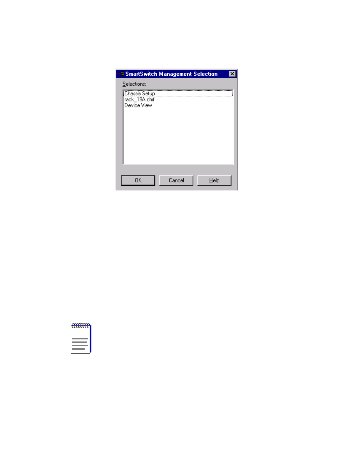
1. In any map, list, or tree view, double-click on the SmartSwitch 6000 or Matrix
E7 you wish to manage. The Management Selection window , Figure2-1, will
appear.
or
1. In any map, list, or tree view, click the left mouse button once to select the
device you wish to manage.
2. Select Manage —> Node from the primary window menu bar, or select the
Manage Node toolbar button. The Management Selection window, Figure 2-1,
will appear.
or
1. In any map, list, or tree view, click the right mouse button once to select the
device you wish to manage.
2. Select Manage from the resulting menu. The Management Selection window,
Figure 2-1, will appear.
2-1
Page 21
The Device View
Figure 2-1. The Management Selection Window
In the Management Selection window, click to select Device View, and click
the OK button. The Device View window, Figure 2-2, will appear.
Viewing Device Information
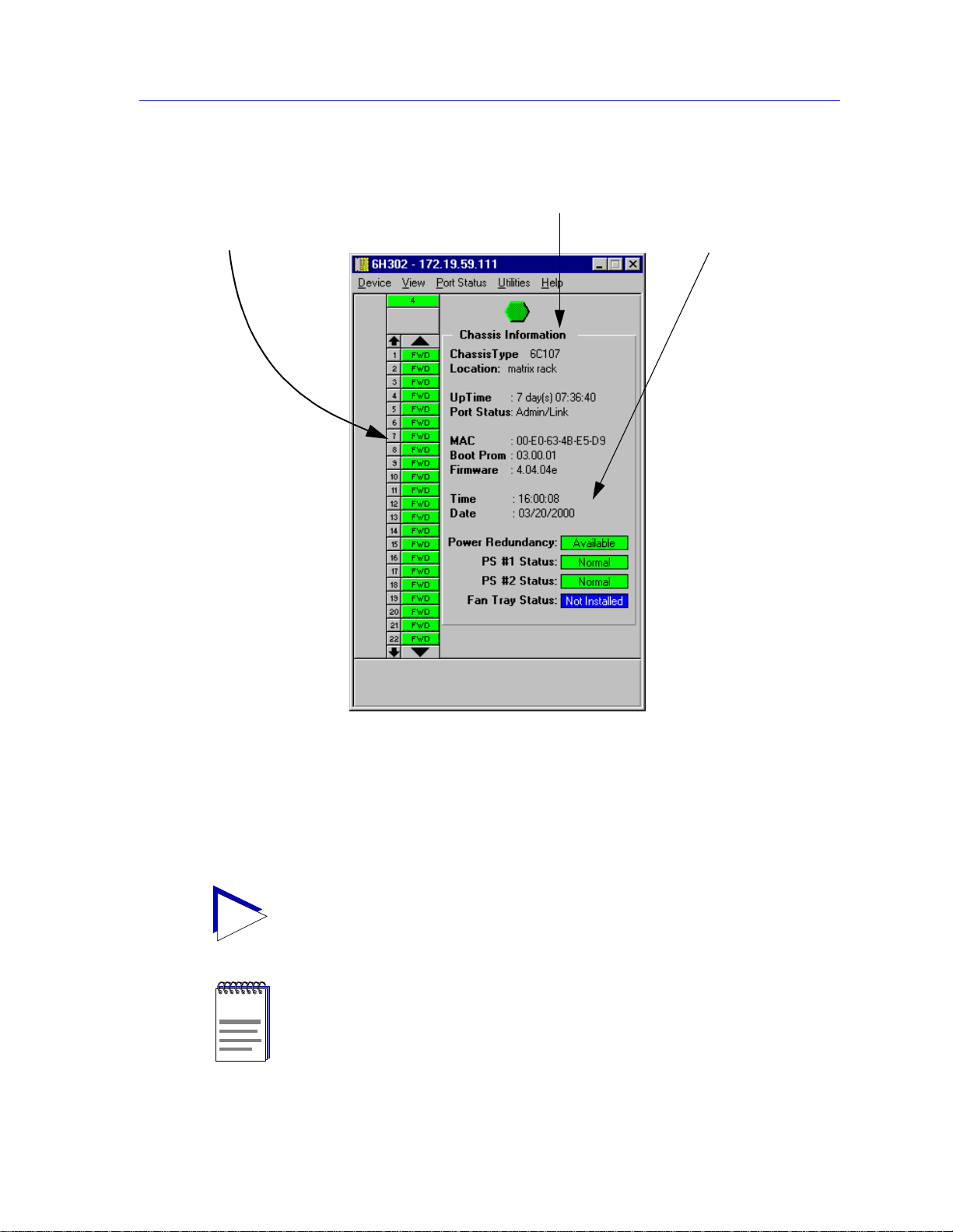
The Device V iew (Figure 2-2) provides a graphic representation of the SmartSwitch 6000
and Matrix E7 chassis and the curr ently mode led SmartSwitch 6000 or Matr ix E7 mo dule,
including a color-coded port display which immediately informs you of the current
configuration and status of all the port interfaces on the module. Note that the module will
appear in its corresponding physical slot in the SmartSwitch 6000 or Matrix E7. Slots are
numbered from 1–5 (for the SmartSwitch 6000) or 1-7 (for the Matrix E7), from left to
right in the chassis.
The Device V iew for HSIMs that have their own IP address and are managed individually
NOTE
(the HSIM-W6, HSIM-W84, and HSIM-SSA710/20), does not show a representation of a
five-slot SmartSwitch 6000 or seven-slot Matrix E7 chassis; it shows only a single-slot
representation.
The Device View also will provide you with environmental status information about the
fan tray and power supplies installed in the chassis.
2-2 Viewing Device Information
Page 22
Module
information
The Device View
General device
information
Chassis-specific
information
Figure 2-2. The Device View Window
By clicking in designated areas of the chassis graphical d isp lay (as detailed later in this
chapter), or by using the menu bar at the top of the Device View window, you can access
all of the menus that lead to more detailed windows.
When you move the mouse cursor over a management “hot spot,” the cursor icon will
TIP
change into a hand symbol to indicate that clicking in the current location will bring up a
management option.
Note that up to 22 ports can be displayed simultaneously on a module. If a module has a
NOTE
higher port density than 22 ports, arrows will appear at the top and bottom of the port
stack so that you can scroll through the remaining ports.
Viewing Device Information 2-3
Page 23

The Device View
General Device Information
In addition to the main interface display, the Device View window provides the following
device information:
IP
The Device View window title displays the device’s IP (Internet Protocol) Address; this
will be the SmartSwitch 6000 or Matrix E7 module IP address used to d e fine the device
icon. The IP address is assigned to the SmartSwitch 6000 or Matrix E7 module via the
Device Configuration portion of Local Management; it cannot be changed via NetSight
Element Manager. Note that although each interface in the SmartSwitch 6000 or Matrix
E7 module has its own MAC, or physical, address, only a single IP address is assigned to
the device.
Connection Status
This color-coded area indicates the current state of communication between NetSight
Element Manager and the SmartSwitch 6000 or Matrix E7 module. If you click this icon,
you can restart the device.
• Green indicates the SmartSwitch 6000 or Matrix E7 module is responding to device
polls (valid connection).
• Magenta indicates that the SmartSwitch 6000 or Matrix E7 module is in a temporary
stand-by mode while it responds to a physical change in the hub (such as when a
module is inserted ). Note that mo dule and por t menus are i nactive during this stand-by
state.
• Blue indicates an unkno wn contact status; polling has not yet been established with t he
SmartSwitch 6000 or Matrix E7 module.
• Red indicates the SmartSwit ch 6000 or Matrix E7 module is not res ponding to dev ice
polls (device is off line, or device pol ling has failed across the network for some other
reason).
Chassis Type
The model of the chassis — 6C105 or 6C107 —þin which the monitored SmartSwitch
6000 or Matrix E7 module is installed.
Location
A descriptive field you can use to id entify where the chassis is physically located. You can
edit this field through the device’s System Group window; refer to the Generic SNMP
User’s Guide for further details.
UpTime
The amount of time, in a days hh/mm/ss format, that the SmartSwitch 6000 or Matrix E7
module has been running since the last start-up. Note that when distributed chassis
management is available, this field will indicate the time that the longest active module
has been running since start-up.
2-4 Viewing Device Information
Page 24

The Device View
Port Status
Indicates the port status display selection currently in effect. The default port status view
is bridge status; if you have not changed the port status selection since launching the
Device View, this field will display Default. For more information about changing the
port status display, see Port Status Displays, on page 2-14.
MAC
Displays the manufacturer-set MAC, or physical, address associated with the IP address
used to define the device icon. This will be the MAC address assigned to the first interface
detected on the SmartSwitch 6000 or Matrix E7 module (although each interface in the
SmartSwitch 6000 or Matrix E7 module has its own MAC address). MAC addresses are
factory-set and cannot be altered.
Boot Prom
The revision of BOOT PROM installed in the SmartSwitch 6000 or Matrix E7 module.
Firmware
The revision of device firmware stored in the SmartSwitch 6000 or Matrix E7 module’s
FLASH PROMs.
Time
The current time, in a 24-hour hh:mm:ss format, set in the SmartSwitch 6000 or Matrix E7
module’s internal clock.
Date
The current date, in an mm/dd/yyyy format, set in the SmartSwitch 6000 or Matrix E7
module’s internal clock.
In accordance with Year 2000 compliance requirements, NetSight Element Manager now
NOTES
displays and allows you to set all dates with four-digit year values.
You can set the da te an d tim e by us ing the Edit Device Date and Edit Device T ime opti ons
on the Device menu; see Setting the Device Date and Time, on page 2-103, for details.
6C105/6C107 Chassis-specific Information
The Device V iew provi des the followi ng informat ion about t he 6C105 o r 6C107 chas sis in
which the SmartSwitch 6000 or Matrix E7 module is installed. There are four color-coded
fields which provide status information for the operation of the power supplies and fan
tray installed in the 6C105/6C107 chassis.
Power Redundancy
The 6C105 and 6C107 support two power supply modules. Each supports a separate AC
input connector, so that two separate power sources can be used for the chassis.
Additionally, with two power supplies installed, the total load presented by the
Viewing Device Information 2-5
Page 25

The Device View
6C105/6C107 and its installed modules is split 50/50 between the supplies (+/- 5%). The
Power Redundancy field displays whether or not the chassis is currently configured for
load sharing and power redundancy. Poss ible values are:
• A v ailable (Green) — Two 6C205-01 or 6C207-01 power su pply modul es are ins talled
in the 6C105/6C107 chassis.
• Not A vailabl e (Y ell ow) — Only a single 6C205-01 or 6C20 7-01 power supply module
is installed in the 6C105/6C107 chassis. Note that when only a single power supply
module is installed, it must always be in power slot 1 (PS1).
PS #1/#2 Status
Indicates the state of any power supplies installed in the 6C105/6C107 Chassis. Possible
states returned are:
• Not Available (Yellow) — No response has been returned from the device regarding
the power supplies.
• Normal (Green) — A power supply is installed and operating in the associated power
slot.
• Fault (Red) — The power supply in the associated power slot is not operational.
• Not Installed (Blue) — The indicated power slot is not occupied by a power supply.
Fan Tray Status
The 6C105/6C107 supports a single, removable fan tray that has four fans. T he tray is hot
swappable, so it can be removed without powering down the chassis. This field indicates
the status of the 6C105/6C107 Fan Tray:
• Not Available (Yellow) — No response has been returned regarding the fan tray.
• Normal (Green) — A fan tray is installed and operational.
• Fault (Red) — One or more fans in the tray have failed.
• Not Installed (Blue) — The fan tray slot is not occupied. The chassis is in danger of
overheating if it continues to run without the fan tray installed.
2-6 Viewing Device Information
Page 26

Menu Structure
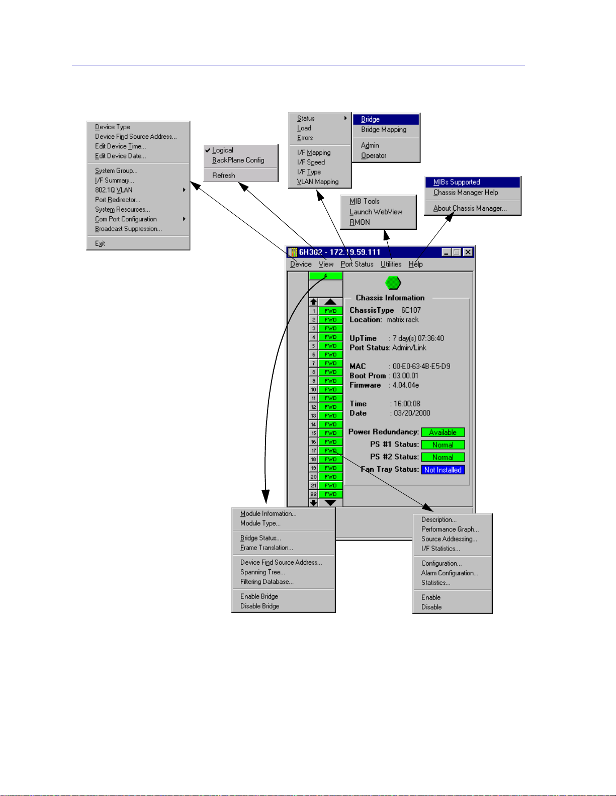
By clicking on various areas of the Device View display, you can access menus with
device-, module-, and port-level options, as well as utility applications which apply to the
device. The following illustration displays the menu structure and indicates how to use the
mouse to access the various menus.
By default, the SmartSwitch 6000 or Matrix E7 module performs traditional switching (or
NOTE
bridging). Depending on the version of firmware you have installed, the module can also
be configured to perform pre-standard 802.1Q VLAN switching or Enterasys SecureFast
Switching. (Check your firmware release notes to see if your version of firmware supports
these features).
For SmartSwitch 60 00 an d Matr ix E7 module s tha t suppo rt 802.1Q VLA Ns or S ecureFast
Switching, the toggle from traditional bridging to 802.1Q or SecureFast Switching is
performed via Local Management. Refer to your Local Management documentation for
details.
When using NetSight Element Manager to manage a device configured for SecureFast
Switching, no bridging-related windows o r port status display options will be available.
All other management options will be a v ailable.
The Device View
Viewing Device Information 2-7
Page 27
The Device View
For the Device menu:
• The FDDI Statistics option will
appear if you have an
HSIM-F6 module installed.
• The ATM Connections option
will appear if you have an
HSIM-A6DP module installed.
• The VLAN option will appear if
your device has been
configured to operate in
802.1Q mode.
• The Priority Configuration
option will appear if your
device supports 802.1P
Dynamic Multicast
Filtering/Priority Queuing.
• The UPS option will only
appear if your COM port has
been configured for use with
an Uninterruptable Power
Supply.
No bridge-related options appear
in any menus if the device is
running in SecureFast Switching
mode.
Figure 2-3. Device View Menu Structure
2-8 Viewing Device Information
Page 28

The Device View
The Device Menu
From the Device menu at the Device View menu bar, you can access the following
selections:
• Device T ype displa ys a window containing a description of the d evice being modeled.
See Device Type, on page 2-26, for details.
• Device Find Source Address enables you to determine which interface a specified
MAC address is communicating through by searching the 802.1d bridge Filtering
database. Ethernet MicroLAN modules (e.g., the 6E123-50 or 6E1 44-49) will also
search the repeater Source Address Table (SAT). If the specified MAC address is
located, a list of interface(s) through which the given address is communicating will
be displayed.
• Edit Device Time and Edit Device Date allow you to set the SmartSwitch 6000 or
Matrix E7 module’s internal clock; see Setting the Device Date and Time, on
page 2-103
• System Group allows you to manage the Sm art Switc h 6 000 or Matrix E7 via SNMP
MIB II. Refer to the Generic SNMP User’s Guide for further information.
• I/F Summary lets you view statistics (displayed both graphically and numerically) for
the traffic processed by each network interface on your device. See Viewing I/F
Summary Information, on page 2-27, for details.
• 802.1Q VLAN appears in the Device menu if your module is configured to operate in
802.1Q mode. The windows launched via the VLAN option allow you to configure
and operate port-based VLANs on the module. See 80 2.1Q VLANs, on page 2-70, for
details.
• ATM Connections appears in the Device menu if you have an HSIM-A6DP installed
in your module. This launches a win dow whi ch let s you configure Permanent V i r tu al
Circuits (PVCs) for the module. See Chapter 7, ATM Configuration, for more
information.
• Port Redirect launches a window that allows you to mirror — or redirect — traffic
received or transmitte d at one p ort o n yo ur mo dul e t o one o r more other ports, so that
you can unobtrusively a ttach network analyzers to ascertain probl ems or trends in your
data flow. For more information about using the Port Redirect window, see
Redirecting Traffic, on page 2-54.
• System Resources displays information about the processor used on the mon itored
SmartSwitch 6000 or Matrix E7 module, as well as the amount of installed and
currently available FLASH memory, DRAM, and NVRAM. See The System
Resources Window, on page 2-66.
• Priority Configuration allows you to establish priority packet forwarding for the
SmartSwitch 6000 or Matrix E7 module. For more information, see Priority
Configuration, on page 2-56.
Viewing Device Information 2-9
Page 29

The Device View
NOTE
The Priority Configuration menu option will only appear in the Device menu for modules
that respond to any of NetSight Element Manager’s queries to the following OIDs:
ctPriorityExtPortStatus, ctPriorityExtMaxNumMACEntries, or
ctPriorityExtNumPktTypeEntries. If your module’s firmware does not respond to these
queries, contact the Enterasys Global Call Center for firmware upgrade information.
• Com Port Configuration allows you to configure the settings of the COM ports on
the SmartSwitch 6000 or Matrix E7 module; see Configuring the COM Port, on
page 2-36, for details.
• Broadcast Suppression allows you to set a threshold on the number of broadcast
packets issued from each port on the SmartSwitch 60 00 or Matrix E7 mod ule whe n it
is operating in traditional switch (bridge) mode. See Broadcast Suppression, on
page 2-64.
• FDDI Statistics option will appear in the Device menu if you have an HSIM-F6
installed in your module. This launches a window which displays traffic-related
statistics for each Station Management (SMT) en tity present on an installed HSIM-F6.
See Chapter 6, FDDI Management, for more information.
• UPS brings up a window that allows you to configure an Uninterruptable Power
Supply attached to your SmartSwitch 6000 or Matrix E7 Module’s COM port. See
Using an Uninterruptable Power Supply (UPS), on page 2-51, for details.
• Exit closes the Device View window.
The View Menu
The View menu lets you switch the front panel display between three graphical
representations of the device:
•The Logical view p rovi des the logical front panel d isplay of the SmartS witch 60 00 or
Matrix E7 module and its interfaces.
•The BackPlane Config view displays the backplane connections between the
SmartSwitch 6000 or Matrix E7 module and other modules installed in the
6C105/6C107 chassis.
• Refresh updates the display.
The Port Status Menu
The Port Status menu allows you to select the status information that will be displayed in
the port text boxes in the Device View:
• Status allows you to select one of four status type disp l ays : B ri dg e , Brid ge Mappi n g,
Admin, or Operator.
• Load will display the portion of network load processed per polling interval by each
interface, expressed as a percentage of its theoretical maximum load (10, 100, 155.5,
800, or 1000 Mbps).
2-10 Viewing Device Information
Page 30

The Device View
• Errors allows you to display the number of errors detected by each interface, since the
last reset, expressed as a percentage of the total number of valid packets processed by
the interface.
• I/F Mapping will display the interface ifIndex associated with each port on your
SmartSwitch 6000 or Matrix E7 module.
• I/F Speed will display the port’s bandwidth: 10M (megabits) for Ethernet; 100M for
Fast Ethernet; 155.5M for ATM; and 800M for the backplane interfaces.
• I/F Type will display the port type of each port on your SmartSwitch 6000 or Matrix
E7 module, e.g., Eth (ethernet-csmacd), ATM, or FDDI.
• VLAN Mapping will appear if your device has been configured to operate in 802.1Q
mode. It displays the VLAN ID number associated with each port on your
SmartSwitch 6000 or Matrix E7 module.
For SmartSwitch 6000 and Matrix E7 Et her net Mi croLAN mo dul es, t he Port Status menu
will contain the following option s:
• Load will display the portion of network load pr ocessed by each port as a percentage
of the theoretical maximum load of the connected network segment (10, 100, 155.5,
800, or 1000 Mbps).
• Port Assignment will display each port’s repeater channel assignment (A-H).
• Status allows you to select one of three status type displays: Admin/Link, Admin, or
Link.
• Errors, and Frame Size allow you to display the percentage per port of the specific
Error or Frame Size you select.
For more information on the port display options avail able via this menu, see Selecting a
Port Status View, on page 2-14.
The Repeater Menu
If you are modeling a SmartSwitch 6000 or Matrix E7 Ethernet MicroLAN module, the
Repeater menu will appear, offering the following options for each repeater segment
(A-H) on the device:
•Statistics
• Timer Statistics
• Performance Graph
• Source Address Type
• Lock/Unlock Ports
•Alarm Limits
• Trap Selection
Refer to Chapter 5, Managing Ethernet MicroLAN Modules, for information on these
menu selections.
Viewing Device Information 2-11
Page 31

The Device View
The FDDI Menu
If your SmartSwitch 6000 or Matrix E7 has an installed HSIM-F6, the FDDI menu will
appear on the Device View menu bar, with the following options:
• Configuration
• Connection Policy
•Station List
• Performance
• Frame Translation
Refer to Chapter 6, FDDI Management, for information on these menu selections.
The Utilities Menu
The Utilities menu provides the followin g selections
• MIB Tools -- provides direct access to the SmartSwitch 6000 or Matrix E7 module’s
MIB information; refer to the Element Manager Tools Guide for more information.
• Launch WebView opens up the Web View for the device, if the device supports it.
• RMON -- a remote monitoring feature that is supported on a per-port basis when at
least one Ethernet or Fast Ethernet module is installed in the chas sis; refer to the
RMON User’s Guide for more information.
These selections are also available from the Tools menu at the top of the primary NetSight
Element Manager window.
The Help Menu
The Help Menu has the following three selections:
• MIBs Supported brings up the Chassis Manager window, described later in this
chapter.
• Chassis Manager Help brings up a help window with in formation specifical ly related
to using the Chassis Manager and Device View windows.
• About Chassis Manager brings up a version window for the Chassis Manager
application in use.
The Module Menu
The Module menu for the SmartSwitch 6000 or Matrix E7 module provides mostly
bridging-related selections, many of which are also available from the B ridge Status
window:
• Module Information opens a Module Information window that provides firmware
and manufacturing information which may be useful when troubleshooting any
problems that you are having with the module. For more information, refer to The
Module Information Window, on page 2-24.
• Module Ty pe brings up a window containing a descript ion of the selected module; see
Viewing Hardware Types, on page 2-25.
2-12 Viewing Device Information
Page 32

The Device View
• Bridge Status opens a window that provides an overvi ew of bridgi ng info rmation for
each port, and allows you to access all other bridge-related options. Refer to the
Bridging chapter in the Element Manager Too ls Guide for more information.
• Broadcast Suppression allows you to set a threshold on the number of broadcast
packets issued from each port on the SmartSwitch 60 00 or Matrix E7 module when it
is operating in traditional switch (bridge) mode.
• HSIM W87 Config (T1) allows you to configure T1 connections for an installed
HSIM-W87; see Chapter 8, HSIM-W87 Configuration, for details.
• IP Priority Config allows you to configure priority transmission for up to 16 IP
addresses for an installed HSIM-W87; see Chapter 8, HSIM-W87 Configuration, for
details.
• Performance Graph appears if there are between one and eight bridge ports, they are
all running at the same speed, and the speed is less than 100 Mb/s. The bridge
performance graph visually displays the combined performance of all bridging
interfaces installed in the SmartSwitch 6000 or Matrix E7 module. Refer to the
Bridging chapter in the Element Manager Tools Guide for more information.
• Spanning Tree allows you to set bridge parameters when it is operating using the
Spanning Tree Algorithm (STA) — the method that bridges use to decide the
controlling (root) bridge when two or more bridges are in parallel. Refer to the
Bridging chapter in the Element Manager Tools Guide for more information.
• SmartTrunk invokes the SmartT runk Configuration and Status Screen, which enables
you to group interfaces logically to achiev e greater bandwidth between devices, if both
devices support the SmartTrunk feature. There is no limit to the number of ports that
can be included in a single “trunk,” nor is there a limit to the number of trunked
“instances” that can be supported. Refer to the Bridging chapter in the Element
Manager Tools Guide for more information.
• Filtering Database lets you see and configure the contents of the 802 .1d bridge St atic
and Filtering Databases. Refer to the Bridging chapter in the Element Manager T ools
Guide for more information.
• Duplex Modes allows you to set Duplex Mode operation for standard Ethernet
interfaces.
• Enable/Disable Bridge enables or disables bridging across every inter face installed in
the SmartSwitch 6000 or Matrix E7 module.
The Port Menus
Each port menu offers the following selections:
• Description displays a text description of the selected port. See Viewing Hardware
Types, on page 2-25, for details.
• Performance Graph appears if the port’s speed is less than 100 mb/s. The resulting
bridge port performance windows visually display bridging performance at the
selected interface. Refer to the Bridging chapter in the Element Manager Tools Guide
for more information.
Viewing Device Information 2-13
Page 33

The Device View
• Source Addressing allows you to view the source MAC addresses communicating
through the currently selected interface.
• HSIM W87 Config (T3) allows you to configure a T3 interface for an installed
HSIM-W87; see Chapter 8, HSIM-W87 Configuration, for details.
• I/F Statistics launches a window that displays MIB-II interface statistics for the
selected interface.
• Configuration allows you to configure Ethernet ports for Standard or Full Duplex
Mode, or configure operational parameters for Fast Ethernet ports, depending on the
type of interface selected.
• Alarm Configuration launches the RMON-based Basic and Advanced Alarm
applications; see Chapter 4, Alarm Configuration, for details. Note that this selection
is available for all bridge port interfaces — even those (like ATM) that do not
specifically support RMON functionality — as lo ng as at least one Ethernet or Fast
Ethernet port is on the module.
•Statistics launches the highest level of statistics currently available for the selected
port. For standard Ethernet and Fast Ethernet ports, RMON statistics will be displayed
if the RMON Default MIB component is active; if it has been disabled, MIB-II
interface statistics will display. See Chapter 3, Statistics, for more information.
• Enable/Disable Port, which activates or disables bridging for the selected port,
respectively; refer to the Bridging chapter in the Element Manager Tools Guide, and
Enabling and Disabling Ports, on page 2-104, for more information.
Port Stat us Displays
When you open the Logical View of the chassis, each port will display its current bridging
state (defined below), with the exception of SmartSwitch 6000 or Matrix E7 Ethernet
MicroLAN ports, which will display their Admin/Link status (also defined below) by
default; to change this status display, select one of the options on the Port Status menu, as
described in the following sections.
Selecting a Port Status View
To change the status view of your ports:
1. Click on Port Status on the menu bar at the top of the Device View window; a
menu will appear.
2. Select the status information you want to display. The port text boxes will
display the appropriate status information.
Port status view options are:
2-14 Viewing Device Information
Page 34

The Device View
Status
You can view four port status categories, as follows:
• Bridge — FWD, DIS, LRN, LIS, BLK, or BRK
• Bridge Mapping — the instance of the physical interface associated with a bridge port
• Admin — ON or OFF
• Operator — ON or OFF
If you have selected the Bridge status mode, a port is considered:
• FWD (Forwarding) if the port is on-line and ready to forward packets across the
SmartSwitch 6000 or Matrix E7 from one network segment to another. This is also the
default display for ports which are administratively enabled but not connected. In
pre-5.1.x firmware, the default state of a por t not in use is “forwarding,” whereas in the
5.1.x firmware, the default is “blocking” (BLK).
• DIS (Disabled) if bridging at the port has been disabled by management; no traf fic can
be received or forwarded on this port, including configuration information for the
bridged topology.
• LIS (Listening) if the port is not adding information to the filtering database. It is
monitoring Bridge Protocol Data Unit (BPDU) traffic while preparing to move to the
forwarding state.
• LRN (Learning) if the Forwarding database is being created, or the Spanning Tree
Algorithm is being executed because of a network topology change. The port is
monitoring network traffic, and learning network addresses.
• BLK (Blocking) if the port is on-line, but filtering traffic from going across the
SmartSwitch 6000 or Matrix E7 from one network segment to another. Bridge
topology information will be forwarded by t he port. In the 5.1.x firmware , t he default
state of a port not in use is “blocking,” whereas in previous firmware versions, the
default is “forwarding” (FWD).
• BRK (Broken) if the physical interface has malfunctioned.
If you have selected the Bridge Mapping status mode, the port display will alter to show
the dot1dBasePortIfIndex, which is the value of the instance of the interface index (the
MIB II ifIndex) that corresponds to each bridge/switch port on the device. For a
SmartSwitch 6000 or Matrix E7 module, the dot1dBasePortIfIndex of the bridge
interfaces will map directly to the ifIndex.
If you have selected the Admin status mode, a port is considered:
• ON if the port is enabled by management.
• OFF if it has not been enabled or if it has been disabled through management action.
The Admin state reflects the state requested by management; depending on the
circumstances, this may or may not match the current Operator status, described below.
Viewing Device Information 2-15
Page 35

The Device View
If you have selected the Operator status mode, a port is considered:
• ON if the port is currently forwarding packets.
• OFF if the port is not currently forwarding packets.
Note that the Operator status provides the actual status of the port; depending on the
circumstances, this may or may not reflect the Admin state currently requested by
management. For example, ports which are administratively ON but not yet connected
would display an Operator status of OFF, since no packets are being forwarded.
Load
If you choose Load, the interface text boxes will display the percentage of network load
processed by each port during the last polling interval. This percentage reflects the
network load generated per polling interval by devices connected to the port compared to
the theoretical maximum load (10, 100, 155.5, 800, or 1000 Mbps) of the connected
network.
Errors
If you choose the Errors mode, the interface boxes will display the percentage of the total
number of valid packets processed by each port during the last polling interval that were
error packets. This percentage reflects the number of errors generated during the last
polling interval by devices connected to that port compared to the total number of valid
packets processed by the port.
NOTE
The polling interval is set using the Device Management page of the Options window,
accessed via the To ols—>O ptions selection fr om the main menu bar. Refer to the Element
Manager User’s Guide for full information on setting node pol ling intervals.
I/F Mapping
If you choose the I/F Mapping mode, the interface boxes will display the interface number
(ifIndex) associated with each port on the SmartSwitch 6000 or Matrix E7 module.
I/F Speed
If you choose the I/F Speed mode, the interface boxes will display the bandwidth of each
individual port on the SmartSwitch 6000 or Matrix E7 module: 10M (megabits) for
standard Ethernet; 100M for Fast Ethernet, 155.5 M for ATM, 800M for a backplane
interface, and 1.00 G for Gigabit Ethernet.
I/F Type
If you choose the I/F Type mode, the interface boxes will display the network type
supported by each interface on the SmartSwitch 6000 or Matrix E7 module, e.g., Eth
(ethernet-csmacd), ATM, or FDDI. Note that there is no type distinction between standard
Ethernet, Fast Ethernet, and Gigabit Ethernet.
Port status view options for a SmartSwitch 6000 or Matrix E7 Ethernet MicroLAN
module are:
2-16 Viewing Device Information
Page 36

The Device View
Load
If you choose Load, the port text boxes will display the percentage of network load
processed by each port during the last polling interval. This percentage reflects the
network load generated by devices connected to the port compared to the theoretical
maximum load (10, 100, 155.5, 800, or 1000 Mbps).
Port Assignment
If you choose Port Assignment, each port’s status box will display a letter which
designates its current repeater channel assignment (A-H).
Status
You can view three status categories for your p orts which reflect six possible Adm in/Link,
Admin, or Link Status conditions:
• Admin/Link — ON, OFF, SEG (segmented), or NLK (not linked)
• Admin — ON or OFF
• Link — LNK (link), NLK (not linked), or N/A (not available)
If you have selected the Admin/Link status mode, a port is considered:
• ON if the port is enabled and has a valid link.
• OFF if it has not been enabled or if it has been disabled through management action.
• SEG (segmented) if the port has been enabled by management and has a valid
connection, but has been segmented by the repeater because 33 consecutive collisions
have occurred on the attached segment, or the collision detector was on for more than
2.4 µs.
• NLK (Not Linked) when the port is on, but there is no physical link to the port. This
field is a combination of two status conditions: No Link and Port Administrative Status
On.
If you have selected the Admin status mode, a port is considered:
• ON if the port is enabled.
• OFF if the port has been disabled by management.
These conditions do not reflect link status.
Viewing Device Information 2-17
Page 37

The Device View
NOTE
If you have selected the Link status mode, a port is considered:
• LNK (Linked) when a valid link has bee n esta blished bet ween t he port and the devi ce
at the other end of the segment.
• NLK (Not Linked) when the port is on, but there is no physical link to the port or the
device at the other end of the port’s segment is down.
• N/A (not available) when NetSight Element Manager cannot determine the link status
for the port.
Because BNC thin coax and AUI ports do not support the link feature, the displayed
Admin/Link, Admin, and Link status co nditions will not always follow the pattern
described above:
Under Admin/Link statu s mo de, BNC ports will display as ON if there is a valid
connection and the por t has b een enabled; OFF if the port has been di sa bled; and SEG if
the port has experienced 33 consecutive collisions or if there is no cable attached. An AUI
port will display as ON i f th e por t has been enabled (regardless of whether or not there is
a valid connection), OFF if the port has been disabled, and SEG if the port has detected
33 consecutive collisions. Note that the Admin/Link status displays for BNC and AUI
ports can be misleading in terms of troubleshooting; be sure to keep in mind that a BNC
port displaying as segmented may only have had its cable disconnected, and an AUI port
that appears to be on and linked may not have any cable attached.
Under Admin status mode, AUI and BNC ports will display as ON if the port has been
enabled, and OFF if it has been disabled; as with other port types, these ON and OFF
conditions indicate nothing about link status.
Under Link status mode, AUI and BNC port display boxes w ill display N/A, indicating
that NetSight Element Manager is u nable to determine their link status.
Errors or Frame Size
If you choose the Errors or Frame Size modes, additional menus offer the following
options for each mode:
Errors Total Errors, Collisions, Alignment, CRC, R unts, Giants, or OOW
Collisions
Frame Size Runts, 64-127, 128-255, 256-511, 512-1023, 1024-1518, or Giants
2-18 Viewing Device Information
Page 38

The port status boxes will display the percentage for each active port that represents what
portion of that port’s total traffic is of the specific type (Errors or Frame Sizes) that you
selected. Select one of the Errors options to see what percentage of the total packets
received by each active port during the last polling interval was of the error type you
selected. This percentage reflects the number of errors generated by devices connected to
that port in relation to the total number of packets processed by the port (errors [errors +
packets]). Choose the Frame Size option to check on the sizes, in bytes, of frames passing
through your ports. The percentages are calculated just like the Errors selection described
above: the number given represents the number of packets of the selected size generated
by devices connected to that port in relation to the total number of packets processed.
Remember, these percentages are calculated based on the numbers of packets processed
during one polling cycle.
Port Status Color Codes
Three of the Port Status display options — Bridge, Admin, and Operator — incorporate
their own color coding schemes: for the Bridge option, green = FWD, blue = DIS,
magenta = LIS or LRN, orange = BLK, and red = BRK; for Admin and Operator, green =
ON, red = OFF, and blue = N/A (not available).
The Device View
For all other Port Status selections — Bridge Mapping, Load, Errors,
I/F Mapping, I/F Speed, and I/F Type — color codes will continue to reflect the most
recently selected mode which incorporates its own color coding scheme.
For a SmartSwitch 6000 or Matrix E7 Ethernet MicroLAN module, three of the port status
display options — Port Assignment, Port Type, and Status — incorporate their own color
coding schemes. For any of th e Status display options — Admin/Li nk, Adm in, o r Link —
green = ON/LNK, yellow = SEG/NLK, red = OFF, and blue = N/A (not available). For the
Port Assignment display option, Channel A = magenta, Channel B = olive, Channel C =
cyan, Channel D = yellow, Channel E = orange, Channel F = white, Channel G = green,
Channel H = hot pink. For the Port Type display option, station p orts will display as
yellow; trunk ports will display as green.
For all other MicroLAN Port Status selections — Load, Errors, and Frame Size — color
codes will continue to reflect the most recently selected mode which incorporates its own
color coding scheme.
Viewing Device Information 2-19
Page 39

The Device View
The Chassis Backplane View
By default, the Device View window displays the Logical View of the 6C105/6C107
Chassis and an installed SmartSwitch 6000 or Matrix E7 module. The Logical View
provides port status information and access to device-, module-, and port-level menus, as
described above. In addition to the default Logical View, the View menu available via the
menu bar at the top of the Device View window allows you to display views of the
chassis’ backplane:
• The Chassis Backplane View indicates the five (for the 6C105) or seven (for the
6C107) point-to-point backplane connections between the monitored SmartSwitch
6000 or Matrix E7 module and other modules in the chassis. The Backplane View also
lets you disable those backplane connections.
The Chassis Backplane View
The Chassis Backplane View, Figure 2-4, indicates the operational status of the five
point-to-point backplane connections between the monitored SmartSwitch 6000 or Matrix
E7 module and other modules in the chassis slots. It also lets you enable or disable the
backplane connections to other modules in the chassis.
To access the Chassis Backplane View:
1. In the Device View, click on View in the menu bar to access the View menu.
2. Click on BackPlane Config. The Chassis Backpl ane View, Figure 2-4, will
appear.
2-20 Viewing Device Information
Page 40

From the Backplane
View you can display
the device interfaces
with respect to their
bridging status or their
MIB II Interface status.
The currently selected
Port Display Form is
shown in the label
above the interfaces.
Below the Port Display
Form label, the
interfaces appear
according to the
currently selected
Display Form. In the
Bridge display form,
you can access
management options
for the individual
interfaces.
The Device View
To change the display form
between Bridge and
Interface, click on the label
and select the desired
display form from the
resulting menu. Bridge is the
default display form.
When the display form is in Bridge mode, clicking on an
interface results in a menu of options applicable to the
selected backplane interface. The Performance Graph
option appears only if the port’s speed is less than 100
mb/s. For information on enabling or disabling the interface,
see Enabling or Disabling a Backplane Interface, on
page 2-23. For details on the remaining menu options, refer
to their entries in The Port Menus, on page 2-13.
Figure 2-4. The Backplane View
Viewing Device Information 2-21
Page 41

The Device View
NOTE
SmartSwitch 6000 cha ssi s: The backplane co nnections are indexed 1– 5, where 1 indicates
the connection to first slot in the chassis and 5 indicates the connection to the last slot.
Matrix E7 chassis: The backplane connections are indexed 1–7, where 1 indicates the
connection to first slot in the chassis and 7 indicates the conn ection to the last slot. Second
generation boards used in the Matrix E7 show only 5 slots.
For Matrix E7 users: Modules for the Matr ix E7 (6C107) chassis are third generation
(6x3xx) boards. Third generation boards are fully supported in any of the 6C107 chassis’
seven slots. Second generation boards (6x2xx SmartSwitch modules) are fully supported
in slots 1-5 in the 6C107 chassis. A second generation board in slot 6 or 7 of the 6C107
will act as a standalone module.
Backplane View Bridge Display Form
When the Backplane View display form is in the default Bridge mode, each connection is
represented by a color-coded text field as follows:
FWD (Green) The interface is on-line and ready to fo rward packets across the
SmartSwitch 6000 or Matrix E7 from one module to another.
DIS (Blue) Bridging at the interface has been disabled by management; no
traffic can be received or forwarded o n this interface, including
configuration infor mat i on for th e br id ged to pology .
LIS (Magenta) The interface is not adding information to the filtering
database. It is monitoring Bridge Protocol Data Unit (BPDU)
traffic while preparing to move to the forwarding state.
LRN (Magenta) The Forwarding database is being created, or the Spanning
Tree Algorithm is being executed because of a network
topology change. The interface is monitoring network traffic,
and learning network addresses.
BLK (Orange) The interface is on-line, but filtering traffic from going across
the SmartSwitch 6000 or Matrix E7 from one module to
another. Bridge topology informat io n wi ll be fo rward ed by t he
interface.
BRK (Red) The interface has malfunctioned.
Backplane View Interface Display Form
When the Backplane View is in Interface mode, each connection is represented by a
color-coded text field that indicates a combination of the interface’s Administrative status,
Operational status, and Link status.
The following status conditions are supported:
UNK (Gray) NetSight Element Manager cannot determine the backplane
interface’s Administrative, Operational, or Link status.
2-22 Viewing Device Information
Page 42

The Device View
ON (Green) The backplane interface is operational (up) and
administratively enabled. Link status is linked, or not
applicable to the interface.
ON (Yellow) The backplane interface is operational (up) and
administratively enabled; however, the interface link status is
Not Linked (NLK).
OFF (Blue) The interface is not operational, and prior to going do wn it was
also administratively disabled.
OFF (Red) The interface is not operational, but prior to going d own it was
in an administratively enabled state.
TEST (Magenta) The interface is in some test operational state.
--- (Gray) The backplane interface is that associated with the slot in
which the currently monitored SmartSwitch 6000 or Matrix E7
module is installed.
Enabling or Disabling a Backplane Interface
You can enable or disable a backplane interface as follows:
1. With the display form in Bridge mode, click on the backplane interface which
you wish to enable or disable. A menu will appear.
2. Select Enable or Disable, as desired.
The SmartSwitch 6000 and Matrix E7 firmware will not allow you to disable the
TIP
operational status of an interfa ce supporting yo ur active net work connectio n. This appl ies
to both backplane and front panel interfaces. If you attempt to disable the backplane
interface to the module that is supporting your active network connection, you will receive
a SET FAILED message.
The Chassis Manager Window
Like most networking devices, Cabletron and Enterasys devices draw their functionality
from a collection of proprietary MIBs and IETF RFCs. In addition, certain Enterasys
intelligent devices — like the SmartSwitch 6000 or Matrix E7 module — organize their
MIB data into a series of “components.” A MIB component is a logical grouping of MIB
data, and each group controls a defined set of objects. For example, SmartSwitch 6000 or
Matrix E7 module bridging information is organized into its own co mponent; Local
Management (LIM) and RMON are also contained in separate components. Note, too, that
there is no one-to-one correspondence be tween MIBs and MIB compon ents; a single MIB
component might contain objects from several different proprietary MIBs and RFCs.
The Chassis Manager window, Figure 2-5, is a read-only window that displays the MIBs
and the MIB component s — and, t herefore, t he function ality — s upported by the curren tly
monitored device.
Viewing Device Information 2-23
Page 43

The Device View
To view the Chassis Manager window:
1. Click on Help on the far right of the menu bar at the top of the Device View
window.
2. Click on MIBs Supported.
The MIBs which provide
the SmartSwitch 6000
and Matrix E7’s
functionality — both
proprietary MIBs and
Figure 2-5. The Chassis Manager Window
The Chassis Manager window will also appear briefly when the Device View window is
NOTE
launched.
The Module Information Window
The Module Information window (Figure 2-6) displays system information, as well as
data provided by the PIC chip (Product Information Chip). The PIC chip, which is updated
each time a module is redesigned, maintains the manufacturing data for the module and
stores certain information such as the MAC addresses of various components. Note that
some devices will not return all the data displayed in the Module Information window;
these fields will remain blank.
MIB Components are
listed here; remember,
there’s no one-to-one
correspondence between
MIBs and MIB
To view the Module Information window:
1. Click on the desired Module Index. The Module menu will appear.
2-24 Viewing Device Information
Page 44

The Device View
2. Click on Module Information. The Module Information window, Figure 2-6,
will appear.
Figure 2-6. The Module Information Window
Firmware Version
The system description of the module, includin g its firmware revision number.
Boot Prom
The revision of boot PROM firmware in the module, incl ud i ng maj or v ers io n n umber and
minor revision number. The boot PROM provides power-on diagnostics and download
capability which enables the module’s system image (which provides its runtime
functionality) to be downloaded over the network.
Top Level Serial Number
The top level serial number of the module associated with this PIC chip which provides
encoded manufacturing date, location , serial number, and top level revision number whic h
can be used for troubleshooting information.
Base MAC Address
The base MAC address (in Ethernet format) assigned to the module.
SMB 1 Prom Version
This field is not applicable to the SmartSwitch 6000 or Matrix E7 module. It will be blank.
Viewing Hardware Types
In addition to the graphical displays d escribed above, menu optio ns available at the device
and module levels provide specific information about the physical characteristics of the
SmartSwitch 6000 or Matrix E7 chassis and its installed modules.
Viewing Device Information 2-25
Page 45

The Device View
Device Type
Module Type
Choosing the Device Type option on the Device menu brings up a window that describes
the management device being modeled.
Figure 2-7. Example Device Type Windows
From the Module menus on the Device View window, you can view a description of the
Module types installed in your chassis.
To view a Module type:
1. Click on the desired Module Index. The Module menu will appear.
2. Click on Module Type. A Module Type text box (similar to the example shown
Interface Description
Choosing the Description option from the Port menu brings up a window that describes
the selected interface.
in Figure 2-8) will appear , describing the module type.
Figure 2-8. Sample Module Type Text Box
2-26 Viewing Device Information
Page 46

Figure 2-9. Sample Interface Description Windows
Viewing I/F Summary Information
The I/F Summary menu option available from the Device menu lets you view statistics
for the traffic processed by each network interface on your device. The window also
provides access to a detailed statistics window that breaks down Transmit and Receive
traffic for each interface.
The Device View
To access the I/F Summary window:
1. From the Device View, click on the Device option from the menu bar.
2. Click again to select I/F Summary. The I/F Summary window, Figure 2-10,
will appear.
Figure 2-10. The I/F Summary Window
Viewing Device Information 2-27
Page 47

The Device View
The I/F Summary window provides a variety of descriptive information about each
interface on your device, as well as statistics which display each interface’s performance.
The following descriptive information is provided for each interface:
Index
The index value assigned to each interface on the device.
Type
The type of the interface, distinguished by the physical/link protocol(s) running
immediately below the network layer. Possible values are fddi (for an installed HSIM-F6),
ethernet-csmacd (for standard, Fast Ether net, and Gigabit Ethernet front pan el interfaces,
as well as the backplane interfaces to the chassis), atm (for an installed HSIM-A6), and
Software LoopBack for the i960 Host Data port.
Description
A text description of the interface: Enterasys Enet or Ethernet Front (for the standard
Ethernet front panel interfaces), Enterasy s F as t or Fast Ethernet (for front panel Fast
Ethernet interfaces), Enterasys Back or FTM Backplane (for the backplane interfaces to
the chassis), Host or Host Data Port for the on-board i960 Host interface, and ATM,
Enterasys ATM, FDDI, or Enterasys FDDI for an installed HSIM.
Physical Status
Displays the current physical status — or operational state — of the interface: Online or
Offline.
Logical Status
Displays the current logical status — or administrative state — of the interface: Up or
Down.
Interface Performance Statistics
The statistical values (and, where available, the accompanying bar graphs) to the right of
the interface description fields provide a quick summary of interface performance. You
can select the statistical value you want to display and th e un its in which you want those
values displayed by using the two menu fields directly above the interface display area, as
follows:
1. In the right-most menu field, click on the down arrow and select the unit in
which you wish to display the selected statistic: Load, Raw Counts, or Rate.
2. Once you have selected the base unit, click on the down arrow in the left-most
field to specify the statistic you’d like to display. Note that the options available
from this menu will vary depending on the base unit you have selected.
After you select a new display mode, the statistics will refresh to reflect the curr ent choice,
as described below.
2-28 Viewing Device Information
Page 48

The Device View
Raw Counts
The total count of network traffic received or transmitted on the indicated interface since
device counters were last reset. Raw counts are provided for the following parameters:
In Octets Octets received on the interface, including framing characters.
In Packets Packets (both unicast and non-unicast) received by the device
interface and delivered to a higher-layer protocol.
In Discards Packets received by the device interface that were discarded
even though no errors prevented them from being delivered to
a higher layer protocol (e.g., to free up buffer space in the
device).
In Errors Packets received by the device interface that contained errors
that prevented them from being delivered to a higher-layer
protocol.
In Unknown Packets received by the device interface that were discarded
because of an unknown or unsupported protocol.
Out Octets Octets transmitted by the interface, including framing
characters.
Out Packets Packets transmitted, at the request of a higher level protocol,
by the device interface to a subnetwork address (both unicast
and non-unicast).
Out Discards Outbound packets that were discarded by the device interface
even though no errors were detected that would prevent them
from being transmitted. A possible reason for discard would be
to free up buffer space in the device.
Out Errors Outbound packets that could not be transmitted by the device
interface because they contained errors.
Load
The number of bytes processed by the indicated interface during the last poll interval in
comparison to the theoretical maximum load for that interface type (10 Mbps for standard
Ethernet; 100 Mbps for Fast Ethernet or FDDI; 155.5 Mbps for ATM; 800 Mbps for a
backplane port; 1000 Mbps for Gigabit Ether net). Load is further defin ed by the following
parameters:
In Octets The number of bytes received by this interface, expressed as a
percentage of the theoretical maximum load.
Out Octets The number of bytes transmitted by this interface, expressed as
a percentage of the theoretical maximum load.
Viewing Device Information 2-29
Page 49

The Device View
Rate
The count for the selected statistic during the last poll interval. The available parameters
are the same as those provided for Raw Counts. Refer to the Raw Counts section,
page 2-29, for a complete description of each parameter.
Viewing Interface Detail
The Interface Statistics window (Figure 2-11) provides detailed MIB-II interface
statistical information — including counts for both transmit and receive p ackets, and error
and buffering information — for each individual port interface. Color-coded pie charts
also let you graphically view statistics for both received and transmitted Unicast,
Multicast, Discarded, and Error packets.
To open the Interface Statistics window:
1. In the I/F Summary window, click to select the interface for which you’d like to
2. Click on Detail. The appropriate I/F Statistics window, Figure 2-11, will
view more detailed statistics.
appear.
Figure 2-11. Detail Interface Statistics
2-30 Viewing Device Information
Page 50

TIP
The Device View
You can also access this information via the I/F Statistics option available on the
individual port menus.
Three informational fields appear in the upper portion of the window:
Description
Displays the interface description for the currently selected interface (e.g., Enterasys Enet
Port, Enterasys Fast Enet Port, FDDI, ATM, or Enterasys Backplane Port).
Address
Displays the MAC (physical) address of the selected interface.
Type
Displays the interface type of the selected port: ethernet-csmacd, fddi, or atm.
The lower portion of the window provides the following transmit and receive statistics;
note that the first four statistics are also graphically displayed in the pie charts.
Unicast
Displays the number of packets transmitted to or received from this interface that had a
single, unique destination address. These statistics are displayed in the pie chart,
color-coded green.
Non-Unicast
Displays the number of packets transmitted to or received from this interface that had a
destination address that is recognized by more than one device on the network segment.
The multicast field includes a count of broadcast packets — those that are recognized by
all devices on a segment. These statistics are displayed in the pie chart, color-coded dark
blue.
Discarded
Displays the number of packets which were discarded even though they contained no
errors that would prevent transmission. Good packets are typically discarded to free up
buffer space when the network becomes very busy; if this is occurring routinely, it usually
means that network traffic is overwhelming the device. To solve this problem, you may
need to re-configure your bridging parameters, or perhaps re-configure your network to
add additional bridges or switch e s. Consult the Enterasys Network Troubleshooting
Guide for more information.
These statistics are displayed in the pie chart, color-coded magenta.
Error
Displays the number of packets received or transmitted that contained errors. These
statistics are displayed in the pie chart, color-coded red.
Viewing Device Information 2-31
Page 51

The Device View
Unknown Protocol
Displays the number of packets received which were discarded because they were created
under an unknown or unsupported protocol.
Packets Received
Displays the number of packets received by the selected interface.
Transmit Queue Size
Displays the number of packets currently queued for transmission from this interface. The
amount of device memory devoted to buffer space, and the traffic level on the target
network, determine how large the output packet queue can grow before the SmartSwitch
6000 or Matrix E7 module will begin to discard packets.
Packets Transmitted
Displays the number of packets transmitted by this interface.
Making Sense of Detail Statistics
The statistics available in this window can give you an idea of how an interface is
performing; by using the statistics in a few simple calculations, it’s also possible to get a
sense of an interface’s activity level:
To calculate the percentage of input errors:
(Received only)
(Received only)
(Transmit only)
(Transmit only)
Received Errors /Packets Received
To calculate the percentage of output errors:
Transmitted Errors /Packets Transmitted
To calculate the total number of inbound and outbound discards:
Received Discards + Transmitted Discards
To calculate the percentage of inbound packets that were discarded:
Received Discards /Packets Received
To calculate the percentage of outbound packets that were discarded:
Transmit Discards /Packets Transmitted
Using the Device Find Source Address Option
To detect the port through which a given MAC address is communicating, use the Device
Find Source Address window.
2-32 Viewing Device Information
Page 52

NOTE
The Device View
When you select the Device Find Source Address option, the device’s 802.1d Filtering
database is searched for the specified MAC address. If it is found, the Component field
will display the value “Bridge” indicating that the addres s was found on a bridging
interface, and the Port Instance field will display the index number assigned to the bridge
port on which the address was located.
You may receive an error message stating “Can’t Display Source Address” if a Port
Instance of “0” or “0.0” is reported. This value indicates that the MAC address is
communicating through the backplane instead of through a front panel interface.
To open the Device Find Source Address window:
1. Click on Device in the Device View menu bar.
2. Click on Device Find Source Address. The Device Find Source Address
window, as shown in Figure 2-12, will appear.
Figure 2-12. Device Find Source Address Window
The Device Find Source Address window displays the following information:
Component
Displays the type of interface through which the specified MAC address is
communicating. This field will report Bridge.
Port Instance
Displays the bridge port index number on which the specified MAC address was found.
Viewing Device Information 2-33
Page 53

The Device View
NOTE
To use the Device Find Source Address window:
1. In the Address Mode field, select the format of the Source Address you wish
to find, either MAC or Canonical.
2. In the Enter Address text box, enter the Source Address you wish to find in
the appropriate XX-XX-XX-XX-XX-XX format.
If you enter the MAC format of a specified address, and then click on Canonical, NetSight
Element Manager will do the address conversion for you. The same is also true if you
enter the Canonical format of a specified address and then select MAC.
3. Click on t he Find It! button. A “Processing Request” message will appear in
the status bar at the bottom of the window.
If the specified MAC address is located, a list of the interface(s) through which the given
address is communicating will appear in the list box. A status message at the bottom of the
window will display the number of interfaces through which the given MAC address is
communicating.
If the specified MAC address cannot be found, a “Source Address not found” message
will appear.
If the MAC address is entered in an incorrect format, an “Invalid MAC Address.
NOTE
Enter Valid MAC Address” message will appear. Enter the address in the correct
XX-XX-XX-XX-XX-XX hexadecimal format.
Using Device Find Source Address on Ethernet MicroLAN Modules
When you select the Device Find Source Address option on an Ethernet MicroLAN
module (e.g., the 6E123-50 or 6E133-49), a search is made of both the Source Address
Table (SAT) and the 802.1d Filtering database to discover through which interface(s) a
specified source MAC address is communicating. If the MAC address is found, the
interface types “Bridge” and “Enet #” will display in the Component field with their
associated port index number displayed in the Port Instance field.
You may receive an error message stating “Can’t Display Source Address” if a Port
NOTE
Instance of “0” or “0.0 ” is reported while us i ng th e Device Find Source Address feature.
This value indicates that the MAC address is communicating through the backplane
instead of through a front panel interface.
To open the Device Find Source Address window:
2-34 Viewing Device Information
Page 54

The Device View
1. Click on Device in the Device View menu bar.
2. Click to select Device Find Source Address. The Device Find Source
Address window, as shown in Figure 2-12, will appear.
Figure 2-13. Device Find Source Address Window
The Device Find Source Address window displays the following information:
Component
Displays the type of interface through which the specified MAC address is
communicating . This field will displa y Bridge and Enet #, indicating that the specified
MAC address was found on a bridging interface and on an Ethernet repeater channel.
Port Instance
Displays the port index number associated with the interface on which the specified MAC
address was found. For an address found on a bridging interface, this field displays the
bridge interface index number on which the specified MAC address was found. For an
address found on a repeater port, this field displays the board (port group) number and the
port index number on which the specified MAC address was found. The board and port
index numbers are separated by a period; for example, a Port Instance of 1.2 refers to
board (port group) 1 and port number 2.
To use the Device Find Source Address window:
1. In the Address Mode field, select the format of the Source Address you wish
to find, either MAC or Canonical.
2. In the Enter Address text box, enter the Source Address you wish to find in
the appropriate XX-XX-XX-XX-XX-XX format.
Viewing Device Information 2-35
Page 55

The Device View
NOTE
NOTE
If you enter the MAC format of a specified address, and then click on Canonical, NetSight
Element Manager will do the address conversion for you. The same is also true if you
enter the Canonical format of a specified address and then select MAC.
3. Click on t he Find It! button. A “Processing Request” message will appear in
the status bar at the bottom of the window.
If the specified MAC address is located, a list of the interface(s) through which the given
address is communicating will appear in the list box. A status message at the bottom of the
window will display the number of interfaces through which the given MAC address is
communicating.
If the specified MAC address cannot be found, a “Source Address not found” message
will appear.
If the MAC address is entered in an incorrect format, an “Invalid MAC Address.
Enter Valid MAC Address” message will appear. Enter the address in the correct
XX-XX-XX-XX-XX-XX hexadecimal format.
Managing the Module
In addition to the performance and configuration information described in the preceding
sections, the Device View also provides you with the tools you need to configure your
SmartSwitch 6000 or Matrix E7 module and keep it operating properly. Hub management
functions include setting operatin g parameters for Ethernet, FDDI, Fast Ethernet, Gigabit
Ethernet and COM ports; managing an attached UPS; redirecting traffic from one module
interface to another; setting port priority parameters; configuring transmission thresholds
for broadcast packets; viewing and configuring system resources; setting device date and
time; and enabling and disabling bridging at specific port interfaces.
Configuring Ports
The Configuration options available for FDDI, Ethernet, Fast Ethernet, Gigabit Ethernet
and COM ports allow you to configure operating parameters specific to each port type: for
FDDI and standard Ethernet ports, you can set the Duplex Mode; for Fast Ethernet ports
on first generation modules, you can set a variety of duplex mode and negotiation
parameters; for Fast Ethernet and Gigabit Ethernet ports on second generation modules
you can set speed, duplex mode , and flow contro l parameters ; and for COM por ts, you can
select the operation you wish the port to perf orm, and set any associated speed p arameters.
FDDI, Ethernet, Fast Ethernet and Gigabit Ethernet Port Configuration windows are
2-36 Managing the Module
Page 56

available from the Device View Port menus (except on Ethernet MicroLAN modules
where they are available from the Bridge Port menu); the COM Port option is available
from the Device menu. Note that no configuration option currently exists for ATM ports.
Configuring Standard Ethernet and FDDI Ports
The Port Configuration window available for both standard Ethernet and FDDI ports
allows you to set an interface to either Standard or Full Duplex Mode. Full Duplex mode
effectively doubles the available wire speed by allowing the interface to both receive and
transmit simultaneously. This window will also display the mode currently in effect on the
selected interface.
T o access the Port Configuration window:
1. From the Device View, click to select the port you wish to configure. The Port
Menu will display.
2. Click on Configuration. The Port Configuration window, Figure 2-14, will
appear.
To access the Port Configuration window on SmartSwitch 6000 or Matrix E7 MicroLAN
modules (e.g., 6E123-50 and 6E133-49):
The Device View
1. In the Device View, click on Device in the menu bar to access the Device
menu.
2. Click on Bridge Status. In the resulting window, click on the Bridge Port
button to access the Bridge Port menu.
3. Click on Configuration. The Port Configuration window, Figure 2-14, will
appear.
Figure 2-14. The Port Configuration Window
Managing the Module 2-37
Page 57

The Device View
TIP
WARNING
If you select the Configuration option availab le for a Fast Ethernet interface, an entirely
different window will appear; see Configuring Fast Ethernet Ports on First Generation
Modules, on page 2-39, or Configuring Ethernet Ports on Second Generation Modules,
page 2-44, for information on configuring these ports.
For standard Ethernet interfaces, Full Duplex should only be enabled on an interface that
has a connection to a single destination address at the other end of the connection (i.e., it
is not a segment with an attached repeater cascadin g the connection to multiple
destination addresses).
Full Duplex mode disables the collision detection circuitry at the interface, so that bo th
Transmit and Receive wir es can be used simultaneously. W ith a single destination addr ess
at the other end of the connection (for example, if the connection was to a full duplex
interface on another switching module, or if a single file server was connected to the full
duplex switch port), this essentially doubles the available bandwidth from 10 Mbit/sec to
20 Mbit/sec. Note that the interface at the other end of the connection must also have Full
Duplex enabled at the attached interface.
Full Duplex mode must be disabled if the interface is communicating with multiple
destinations simultaneously (i.e., if a repeater is cascaded from the interface), since
Ethernet relies on Collision Sense for proper operation.
Similarly, an FDDI Full Duplex connection must also only be run point-to-point between
two supporting FDDI interfaces (e.g., another HSIM-F6), since the dual bandwidth is
attained by running data on both pr imary and s econdar y paths simul tane ously. Since Full
Duplex overrides standard FDDI protocol (and eliminates ring redundancy), it will not
operate in a “ring” configuration, but only as a point-to-point high speed data trunk
between hubs. Note that you must use Local Management to configure your HSIM-F6 for
Full Duplex operation prior to making physical connections. Refer to your Local
Management Guide for more information.
Use the options in this window to select the desired mode:
Standard Mode
In Standard Mode, an interface can only either transmit or receive at any given time, and
must wait for one activity to be completed before switching to the next activity (receive or
transmit). In this mode, st andar d wire s peed s (10 Mbp s f or Ethern et, 10 0 Mbp s for F DDI)
are available.
Full Duplex
In Full Duplex Mode, an interface can bo th r eceive and transmit packets at the same time,
effectively doubling the available wire speed to 20 Mbps (for Ethernet) or 200 Mbps (for
FDDI).
Be sure to click on the Apply button to set your changes; note that the interface’s current
mode can be determined by the field selected in the window.
2-38 Managing the Module
Page 58

Configuring Fast Ethernet Ports on First Generation Modules
The Fast Ethernet Configuration window available for Fast Ethernet ports on first
generation modules (e.g., 6H1 22-xx an d 6H128-0 8) allows you to both view and set t hose
ports’ available modes. All 100Base-TX Fast Ethernet ports can be configured to operate
in either standard Ethernet (10 Mbps) or Fast Ethernet (100 Mbps) mode, and in each
mode can be configured to operate in Full Duplex, effectively dou bling the available wire
speed (from 10 to 20 Mbps in standard Ethernet mode, or from 100 to 200 Mbps in Fast
Ethernet mode); 100Base-FX (fiber) ports can be configured to operate in their standard
100 Mbps mode, or in Full Dupl ex mode. Th is window al so display s the mod e currently in
effect on the selected interface, and provides some information (where it is available)
about the interface’s link partner.
To access the Fast Ethernet Configuration Window:
1. From the Device View, click to select the port you wish to configure; the Port
Menu will display.
2. Click on Configuration. The Fast Ethernet Configuration window,
Figure 2-15, will appear.
To access the Fast Ethernet Configuration window on SmartSwitch 6000 or Matrix E7
MicroLAN modules (e.g., 6H123-50):
The Device View
1. In the Device View, click on Device in the menu bar to access the Device
menu.
2. Click on Bridge Status. In the resulting window click on the Bridge Port
button to access the Bridge Port menu.
3. Click on Configuration. The Fast Ethernet Configuration window,
Figure 2-14, will appear.
Managing the Module 2-39
Page 59

The Device View
NOTE
TIP
Figure 2-15. The Fast Ethernet Port Configuration Window
Auto-Negotiation is not s upp or t ed by t he FE-1 00FX Fast Et her net po rt i nte rfa ce modul e.
If you launch the window for a port module slot which has no FE module installed, the
Port Type will display as Unknown, the Link State will display No Link, and the rest of the
fields will be blank and/or grayed out.
If you select the Configurat ion option a vailable for a s tandar d Et hernet or FDDI interf ace
or for an Ethernet port on a second generation module, an entirely different window will
appear; see Configuring Standa rd Eth ernet an d FDDI Po rts , page 2-37, or Co nfig urin g
Ethernet Ports on Second Gene ration Modules, page 2-44, for information on
configuring these port s.
From this window you can manually set the operational mode of the port, or — for
100Base-TX interfaces — set the port to Auto-Negotiation so that the appropriate
operational mode can be determined automatically. The mode you set will determine the
speed of the port and whether it uses Full Duplex or Standard Mode bridging.
2-40 Managing the Module
Page 60

The Device View
The window displays the following information about the selected Fast Ethernet port:
Port Type
Displays the port’s type: 100Base-TX RJ-45 (for built-in Fast Ethernet ports and the
FE-100TX Fast Ethernet port module), 100Base-FX MMF SC Connector (for the
FE-100FX Fast Ethernet port module), or Unknown (for a port slot with no module
installed).
Link State
Displays the current connection status of the selected port: Link or No Link.
Current Operational Mode
Indicates which of the available operational modes is currently in effect: 10Base-T,
10Base-T Full Duplex, 100Base-TX, 100Base-TX Full Duplex, 100Base-FX, or
100Base-FX Full Duplex. If the port is still initializin g, not linked, or if there is no port
module installed in the slot, this field will remain blank.
Desired Operational Mode
Displays the operational mode that you have selected for th is port, and allows you to
change that selection. The following operational modes are available for each port:
!
CAUTION
100Base-TX Auto-Negotiation, 10Base-T, 10BASE-T Full Duplex, 100Base-TX,
and 100Base-TX Full Duplex.
100Base-FX 100Base-FX and 100Base-FX Full Duplex
If you choose to select a specific mode of operation (rath e r than auto-negotiation), you
should be sure that the link partner supports the same mode. Otherwise, no link will be
achieved.
If you select a Full Duplex mode and the link partner supports the same wire speed but not
Full Duplex, a link will be achieved, but it will be unstable and will behave erra tically.
If you select Auto-Negotiation, the local node will try to match the mode of the link
partner, even if the link partner is not set to auto-negotiate, and even if the local node must
use a mode which it is not currently advertising.
Note that if Auto-Negotiation is the selected mode, the Current Operational Mode field
will indicate which mode was selected by the link partne r.
See Setting the Desired Operational Mode, on page 2-42, for more information.
Advertised Abilities
For 100Base-TX ports which have been configured to operate in Auto-Negotiation mode,
this field allows you to select which of the operational modes available to the port can be
selected by the negotiating link partners.
Managing the Module 2-41
Page 61

The Device View
NOTE
During Auto-Negotiation, each of the link partners will advertise all selected modes in
descending bandwidth order: 100Base-TX Full Duplex, 100Base-TX, 10Base-T Full
Duplex, and 10Base-T. Of the selected abilities, the highest mode mutually available will
automatically be used. If there is no mode mutually advertised, no link will be achieved.
If you have selected a specific operational mode for your 100Base-TX port, the
Advertised Abilities do not apply; the selected Advertised Abilities also do not restrict the
local node’s ability to set up a link with a partner who is not currently Aut o-Negotiating.
Auto-Negotiation is not currently supported for 100Base-FX ports.
Remote Capabilities
When the local node is set to Auto-Negotiation, this field will display the advertised
abilities of the remote link — even if the remote link is not currently set to auto-negotiate.
Possible values for this field are:
NOTE
• 100Base-TX Full Duplex
• 100Base-TX
• 10Base-T Full Duplex
• 10Base-T
• Link Partner does not support Auto-Negotiation — Auto-Negotiation is either not
supported by or is not currently selected on the remote port.
• Unknown — the link partner ’s capabilities could not b e determ ined.
When the local node is not set to Auto-Negotiation, this field will be grayed out, even if
the link partner is set to Auto-Negotiation and is advertis ing abilities.
If both link partners are set to Auto-Negotiation, but there is no mutually-advertised
operational mode, no link will be achieved, and both nodes may display the message
“Link Partner does not support Auto-Negotiation.” T o resolve this situation, be sure both
link partners advertise all their abilities, or be sure they advertise at least one
mutually-available mode.
Setting the Desired Operational Mode
For any 100Base-TX port, you can specifically choose any one of the four available
operational modes, or you can select Auto-Negotiation mode, which allows the port to
negotiate with its link partner to find the highest m utually available bandwidth. If you
select Auto-Negotiation mode, you must also choose which of the port’s bandwidth
capabilities you wish to advertise to the link partner.
2-42 Managing the Module
Page 62

TIP
The Device View
If you select Auto-Negotiation at both ends of a link, be sure at least one
mutually-advertised operational mode is available.
For a 100Base-FX port, the selection process is somewhat simpler; Auto-Negotiation for
these ports is not supported at this time, so you need only choose between 100Base-FX
standard mode and 100Base-FX Full Duplex. However, you must still be sure that both
link partners are set to the same operational mode, or the link will be unstable.
To set your desired operational mode:
1. Click on the Desired Operational Mode list box to display the menu of
available options; click to select the operational mode you wish to set.
For 100Base-TX ports, the available options are:
Auto Negotiation — the operational mode will be dynamically set based on
the modes selected in the Advertised Abilities field (where both link partners
are auto-negotiating) and the speeds and modes supported by the attached
device
TIP
10Base-T — 10 Mbps connection, Standard Mode
10Base-T Full Duplex — 10 Mbps connection, Duplex Mode
100Base-TX — 100 Mbps connection, Standard Mode
100Base-TX Full Duplex — 100 Mbps connection, Duplex Mode
For 100Base-FX ports, options are:
100Base-FX — 100 Mbps connection, Standard Mode
100Base-FX Full Duplex — 100 Mbps connection, Duplex Mode
2. If you have selected Auto-Negotiation (for 100Base-TX ports only), use the
Advertised Abilities field to select the operational capabilities you wish to
advertise to the port’s link partner. If both link partners will be auto-negotiating,
be sure there is at least one mutually-advertised operational mode, or no link
will be achieved.
The selected Advertised Abilities only come into play when both link partners are
auto-negotiating; if only one link partner is set to auto-negotiate, that node will establish
a link at whatever mode its partner is set to, even if that mode is not currently being
advertised.
Managing the Module 2-43
Page 63

The Device View
3. Click on the Apply button to save your changes. Click on the Refresh button
to display the new settings. Note that it may take a few minutes for mode
changes to be completely initialized, particularly if the link partners must
negotiate or re-negotiate the mode; you may need to refresh the window a
few times before current operational data is displayed.
Configuring Ethernet Ports on Second Generation Modules
The Ethernet Configuration wi ndow availab le for Fast Ethernet and Gig abit Ethernet ports
on second generation modules (e.g., 6E233-49 and 6H258-17) allows you to both view
and set those ports’ available speed, modes, and flow control. All second generation
modules support t he ctEthernetParameters MIB. All Ethernet ports that return at least one
instance for a query of the ctEtherSupportedDuplex OID will use the Ethernet
Configuration window as shown in Figure 2-16.
All 100Base-TX Fast Ethernet ports can be configured to operate in either standard
Ethernet (10 Mbps) or Fast Ethernet (100 Mbps) mode, and each mode can be configured
to operate in Full Duplex effectively doubling the available wire speed (from 10 to 20
Mbps in standard Ethernet mode, or from 100 to 200 Mbps in Fast Ethernet mode).
100Base-FX (fiber) ports can be configured to operate in their standard 100 Mbps mode,
or in Full Duplex mode. 1000Base-SX/LX/CX Gigabit Ethernet ports are always
configured to operate in 1000 Mbps, Full Duplex mode.
This window displays the mode currently in effect on the selected interface, and provides
some information (where it is available) about the interface’s link partner.
T o access the Ethernet Configuration Window:
1. From the Device View, click to select the port you wish to configure; the Port
Menu will display.
2. Click on Configuration. The Ethernet Configuration window, Figure 2-15, will
appear.
2-44 Managing the Module
Page 64

The Device View
TIP
Figure 2-16. The Ethernet Configuration Window
If you select the Configurat ion option a vailable for a s tandar d Et hernet or FDDI interf ace
or for a Fast Ethernet port on a first generation module, an entirely different window will
appear; see Configuring Standard Et hernet and FDDI Po rts, pa ge 2-37, or Conf igu rin g
Fast Ethernet Ports on First G e neration Modules, page 2-39, for information on
configuring these port s.
From this window you can manually set the operational mode of the port, or — for
100Base-TX and 1000Base-SX/LX/CX interfaces — set the port to Auto Negotiate so that
the appropriate operational mode can be determined automatically. The mode you set will
determine the port’s speed, duplex mode, and flow control.
The window displays the following information about the selected Ethernet port:
Port Type
Displays the port’s type: 100Base-TX RJ-45or RJ71 (for built-in Fast Ethernet ports and
the FE-100TX Fast Ethernet port module), 100Base-FX MMF SC Connector (for the
Managing the Module 2-45
Page 65

The Device View
FE-100FX Fast Ethernet port modul e), 1000Bas e-SX/LX/CX (for the VHSI M-G6 Gigabit
Ethernet port module), or Unknown (for a port slot with no module installed).
Link State
Displays the current connection status of the selected port: Link or No Link.
Remote Auto Signal
Indicates whether the operating mode at the remote end of the link is set to Auto
Negotiate.
Auto Negotiate Config
Indicates whether Auto Negotiate signalling is in progress or has completed. Possible
values for this field are: configuring, complete, disabled, parallel detect failed, or other.
Auto Negotiate Mode
Use this field to enable or disable Auto Negotiate for the port. If Auto Negotiate is
disabled, the port will use the speed, duplex mode, and flow control settings specified in
the Operational Mode fields. Note that 100-BaseFX ports do not support Auto
Negotiation; they must use the control settings specified in the Operational Mode fields.
!
CAUTION
Operational Mode Fields
If the port is not set to Auto Negotiate then the settings in the Operational Mode fields are
used.
If you choose to select a specific mode of operation (rath e r than auto negotiation), you
should be sure that the link partner supports the same mode. Otherwise, no link will be
achieved.
For example, if you select Full Duplex mode and the link partner supports the same wire
speed but not Full Duplex, a link will be achieved, but it will be unstable and will behave
erratically.
If you select Auto-Negotiation, the local node will try to match the mode of the link
partner, even if the link partner is not set to auto-negotiate, a nd even if the local node must
use a mode which it is not currently advertising.
The Current Operational Mode settings indicate which of the available operational
modes is currently in effect. If Auto Negotiate is the selected mode, the Current
Operational Mode fields will indicate which mode was selected by the link partner.
The Desired Operational Mode settings display the operational mode that is currently
selected for this port, and allows you to change the selection.
The following operational modes can be specified:
Speed
This field specifies a port speed of 10MB, 100MB, or 1000MB.
2-46 Managing the Module
Page 66

The Device View
Duplex
This field specifies Half Duplex or Full Duplex mode for the port.
Flow Control
Flow control allows Ethernet devices to notify attached devices that congestion is
occurring and that the sending device should stop transmitting until the congestion can be
cleared. There are two commonly used methods of flow control: Frame-based (operates on
Full Duplex links) and Backpressure (operates on Half Duplex links).
Ports set to Full Duplex mode have frame-based flow control, using pause control
frames. Frame-based flow control options are:
Symmetric The port is able to both receive and transmit pause control frames.
Asymmetric RX This option appears only for Gigabit Ethernet ports. The port will
receive pause control frames, but will not transmit its own.
Asymmetric TX This option appears only for Gigabit Ethernet ports. The port is
capable of sending pause control frames, but will not acknowledge
received pause control frames.
Disabled Disables flow c ontrol on the port.
Auto Negotiate Ports co nfigured to operate in auto negotiation mode will only use
pause control frames if the negotiation process determines that the link
partner supports them. Both ends of the link must support auto
negotiation and a common mode of operation.
Ports set to Half Duplex mode use Backpressure flow control. Backpressure flow control
simply asserts the carrier sense signal out the port causing the device transmitting to detect
a collision, stop transmitting data, and sen d the jam signal. Backpressure flow control
options are enabled or disabled.
Setting the Desired Operational Mode
For any 100Base-TX port, you can configure operational modes, or you can select Auto
Negotiate mode, which allows the port to negotiate with its link partner to find the highest
mutually available bandwidth and flow control. If you select Auto Negotiate mode, you
must also choose which of the port’s bandwidth and flow control capabilities you wish to
advertise to the link partner (refer to Auto Negotiation Technologies, page 2-48).
100Base-FX ports do not support auto negotiation for bandwidth or flow control
capability, so you must choose between 100Base-FX Half Duplex and 100Base-FX Full
Duplex mode, and set the flow control option. H owever, you must still be sure that both
link partners are set to the same operational mode, or the link will be unstable.
For 1000Base-SX/LX/CX ports the speed and duplex modes are always configured at
1000MB Full Duplex. However, you can select Auto Negotiate mode, which allows the
port to negotiate with its link partner to find the highest mutually available bandwidth and
flow control. If you select Auto Negoti ate mod e, you must also choose which of the port ’s
bandwidth and flow control capabilities you wish to advertise to the link partner (refer to
Auto Negotiation Technologies, page 2-48).
Managing the Module 2-47
Page 67

The Device View
NOTE
To set your desired operational mode:
1. Click on the Speed, Duplex, or Flow Control list box to display the menu of
available options; click to select the operational mode you wish to set.
If the port you are configuring does not support Flow Control, the Current Mode field will
display “not supported” and the Desired Mode list box will be disabled.
2. Click on the Apply button to save your changes.
Auto Negotiation Technologies
For ports which have been configured to operate in Auto Negotiate mode, this list box
allows you to select which of the operational modes available to the port will be advertised
to the negotiating link partner.
During Auto Negotiation, each of the link partners will advertise all selected modes. Of
the selected modes, the highest mode mutually available will automatically be used. If
there is no mode mutually advertised, no link will be achieved.
TIP
If you select Auto-Negotiation at both ends of a link, be sure at least one
mutually-advertised operational mode is a v ailable.
If you have manually configured s pecifi c op erati onal mo des for y our 100Base-TX port or
if you are configuring a 100Base-FX port, the Auto Negotiation Technologies list box
does not apply.
The Auto Negotiation Technologies list box has the following column headings:
Advertised
This column specifies whether the operational mode listed in the far right column of the
list box will be advertised to the link partner. Only those operational modes supported by
the local port (those with a “yes” listed in the Local column) can be advertised. Valid
values are Enabled (the mode is supported and will be advertised), Disabled (the mode is
supported but will not be adve rtised), and “---” (the mode is not supported).
Local
Indicates whether the operational mode listed in the far right column of the list box is
supported by the local port.
Remote
Indicates whether the operational mode listed in the far right column of the list box is
supported by the remote port.
2-48 Managing the Module
Page 68

The Device View
Auto Negotiate Technology
This column lists possible operational modes.
Setting Advertised Abilities for Auto Negotiation
You can determine which operational mode supported by the local port will be advertised
to the negotiating link partner. Of the advertised modes, the highest mode mutually
available will automatically be used.
To advertise an operational mode:
1. In the list box, click on the operational mode of choice.
If the Advertised column had a value of Enabled, it will change to Disabled; a
value of Disabled will change to Enabled. If the Advertised column has a
value of “---”, then the value is not changed.
2. Click on the Apply button to save your changes. Click on the Refresh button
to display the new settings. Note that it may take a few minutes for mode
changes to be completely initialized, particularly if the link partners must
negotiate or re-negotiate the mode; you may need to refresh the window a
few times before current operational data is displayed.
Configuring the COM Port
You can use the COM Port Configuration window (Figure 2-17) to specify the functions
that will be performed by the RS232 COM port on the front panel of the monitored
SmartSwitch 6000 or Matrix E7 module. To do so:
1. Click on Device in the Device View menu bar to display the Device menu.
2. Click on COM Port Configuration and then select Port 1. The COM Port
Configuration window, Figure 2-17, will appear.
Figure 2-17. The COM Port Configuration Window
Managing the Module 2-49
Page 69

The Device View
You can use the COM Port Configuration window to set the following operating
parameters:
COM Port Admin
Use this field to administratively enable or disable the COM port.
COM Port Function
Use this field to select the function for which you wish to use the COM port:
LM Local Management: select this option if you wish to connect a terminal
to the COM port from which to run Local Management.
UPS Select this option if you wish to connect an uninterruptable power
supply (UPS) to the COM Port. Note that if you select this option, an
additional option — UPS — will appear on the Device menu when yo u
exit and re-enter device management; use the resulting window to
configure specific UPS settings.
SLIP Select this option to use the COM port as a SLIP connection for
out-of-band SNMP management via direct connection to a serial por t on
your network management workstation. Note that when you configure
the port as a SLIP connection, you must select the desired baud rate in
the Speed Selection field described below.
NOTE
TIP
PPP Select this option to use the COM port as a PPP connection for
out-of-band SNMP management via direct connection to a serial por t on
your network management workstation. Note that when you configure
the port as a PPP connection, you must select the desired baud rate in
the Speed Selection field, page 2-50.
Current SmartSwitch 6000 or Matrix E7 firmware versions support only Local
Management and UPS via the COM ports; future versions will add SLIP and PPP
support. You will receive a SET failed message if you attempt to configure the COM port
for SLIP or PPP support.
Speed Selection
If you have configured the selected port as a SLIP or PPP connection, you must select the
appropriate baud rate: 2400, 4800, 9600, or 19,200. Note that this field will default to
Auto-Baud and become unselectable when the COM Port Function is set to LM or UPS.
If the COM port you wish to configure is currently set to LM or UPS, the Speed Selection
field will be unavailable until the COM Port Function is set to SLIP or PPP and that
change is applied. Once available, the Speed Selection field will default to the last know n
speed setting; use the down arrow to change this setting if necessary, then click the Apply
button again to complete th e configuration.
2-50 Managing the Module
Page 70

To change the configuration of the selected COM port:
1. Click on the arrow to the right of each field.
2. Drag down to select the desired setting, then release.
3. Click on the Apply button to save your changes.
Using an Uninterrupt able Power Supply (UPS)
Your SmartSwitch 6000 or Matrix E7 supports the use of a UPS (uninterruptable power
supply) through its COM port (if configured through local management). (For more
information on the use of a UPS with the SmartSwitch 6000 or Matrix E7, co nsult the
SmartSwitch 6000 or Matrix E7 Installation Manual that was included when you
purchased the unit.) You can view or change the status of the UPS connected to your
SmartSwitch 6000 or Matrix E7 at the UPS window.
Please note that the UPS window will only be active if you currently have a UPS attached
to your SmartSwitch 60 00 or Matr ix E7 thro ugh the C OM por t, and yo u ha ve correctl y set
the Set UPS ID field.
The Device View
Do not set the Set UPS ID field unless you have a UPS attached to the SmartSwitch 6000
WARNING
Accessing the UPS Window
or Matrix E7, or you will disrupt your use of NetSight Element Manager.
At the UPS window, you can configure the UPS ID model type for the uninterruptable
power supply you have attached to the COM port on your device.
You can also view information concerning the UPS connected to your SmartSwitch 6000
or Matrix E7 including:
• The amount of time that your UPS has been running since the last start-up
• The line voltage and battery output
• The actual battery capacity of the UPS (dynamic bar graph)
You can also use a butt on at the bo ttom of the windo w to discon nect yo ur UPS, or y ou can
use the Test option to initiate a self test of the unit.
T o access the UPS window:
1. From the Device View window, click on Device in the menu bar to access the
Device menu.
2. Click on UPS. The UPS window , Figure 2-18, will appear.
Managing the Module 2-51
Page 71

The Device View
Figure 2-18. The UPS Window
UPS ID
Displays the manufacturer and model typecode of the UPS attached to the COM port of
the SmartSwitch 6000 or Matrix E7. You must assign this typecod e for the UPS wind ow
to be active. (See Setting the UPS ID, on page 2-53, for instructions for setting the
typecode for your UPS.) The valid typecodes are:
• Model 370
• Model 400
• Model 600
• Model 900
• Model 1250
• Model 2000
• Matrix 3000
• Matrix 5000
•SU 700
• SU 1400
• SU 2000XL
•Other
UPS Uptime
Displays the number of hours that the UPS has been operating since the last time it was
started up.
2-52 Managing the Module
Page 72

The Device View
Line Voltage
Displays the voltage coming through the line attached to the SmartSwitch 6000 or Matrix
E7.
Battery Output
Displays the amount of battery output voltage.
Battery Capacity
Displays the percentage of remaining battery capacity (100% indicates a fully charged
battery).
Test Results
Displays the result of the last self-test performed by the UPS. The possible test results are:
Unit OK The UPS unit is in working order.
Unit Failed The UPS unit has failed the self-test. Check the unit
for damage or consult your UPS user’s manual.
Bad Battery The UPS unit battery is bad.
No recent test No UPS self-test has been performed in the last five
minutes.
Unit in test... The UPS is currently in test mode.
Please standby
Setting the UPS ID
You need to set the UPS ID typecode that indicates the manufacturer and model of the
UPS.
To set the UPS ID:
1. Click on the arrow next to the SET UPS ID text box. A Model number menu
2. Click on the OK button. The UPS ID you have chosen will appear in the text
If your UPS unit does not function after you have set this ID, check the manual you
received with the UPS to ensure that you have chosen the correct UPS ID. If you need to
change the ID, follow the directions given above.
Using the Test Option
will appear. Scroll to highlight the appropriate UPS ID. (Consult the manual
that was included when you purchased your UPS for the correct Model ID
number.)
box, and the UPS window will be active.
You can use the test option to activate a self-test cycle for your unit. This self-test will
check the viability of your unit and it s battery.
Managing the Module 2-53
Page 73

The Device View
T o activate the test:
1. Click on the Test button. The unit will begin its self-test. The results of the test
will appear in the Test Result text box next to the Test button.
Using the Disconnect Option
You can disconnect the UPS attached to your SmartSwitch 6000 or Matrix E7 through its
COM port, as follows:
1. Click on the Disconnect button near the bottom of the UPS window. Your
UPS will now be disconnected.
To reconnect, simply click on the OK button, or close, then re-open the UPS window.
Redirecting Traffic
The Port Redirect window (Figure 2-19) allows you to redirect traffic from one or more
interfaces directly to another interface — essentially mirroring the traffic at the “redirect”
interface. This feature is useful in that it allows you to use an external analyzer on the
“redirect” port to analyze data, without disturbing the normal switching operations at the
original source ports. The Port Redirect window displays the interface remap table and
allows you to add new entries to and delete existing entries from this table. When you set
a source port to redirect to a destination port, the destination po rt wi ll transmit out all
packets received or transmitted on the source port.
To access the Port Redirect window:
1. In the Chassis View window, select Device>Port Redirect (if you are
managing a single device) or Chassis>Port Redirect (if you are managing a
chassis with multiple modules). The Port Redirect window, Figure 2-19,
appears.
2-54 Managing the Module
Page 74

The Device View
Figure 2-19. The Port Redirect Window
Chassis IP Address, Chassis Commun i ty Name, and the Contact button appear only if
NOTE
the chassis is a S martSwi tch 600 0 with an assign ed IP ad dr ess. In or der t o see the Cu rr ent
Active Entries for this type of device, you must enter the Chassis IP Address and
Community Name, then click Contact.
The current port mappings are listed in the Current Active Entries list. You may add or
delete entries in this list.
Not all devices support the Source Module and Destination Module fields.
NOTE
Managing the Module 2-55
Page 75

The Device View
T o add an entry:
1. SmartSwitch 6000 with assigned IP address only: Enter the Chassis IP
Address and the Chassis Community Name, then click Contact to display
the Current Active Entries.
2. If applicable: Click the arrow next to Source Module and select the desired
source module from the drop-down list.
3. Click the arrow next to Source Port and select the desired source port from
the drop-down list.
4. If applicable: Click the arrow next to Destination Module and select the
desired destination module from the drop-down list.
5. Click the arrow next to Destination Port and select the desired destination
port from the drop-down.
6. Click Add. The new entry is displayed in the Current Active Entries list, and
redirection of the port traffic will begin.
To delete an entry:
1. SmartSwitch 6000 with assigned IP address only: Enter the Chassis IP
Address and the Chassis Community Name, then click Contact to display
the Current Active Entries.
2. In the Current Active Entries list, click to highlight the entry you wish to delete.
3. Click Delete. The entry is deleted from the Current Active Entries list and the
traffic from the source port will no longer be redirected to the destination port.
Priority Configuration
The SmartSwitch 6000 and Matrix E7 modules support priority packet forwarding.
Priority packet forwarding lets you designate certain packets to be of higher importance
than others, thereby allowing for the forwarding of these packets before packets of lower
priority. This functionality is essential for time-critical applications — such as real-time
video — on shared networks.
The Priority Configuration menu option will only appear in the Device menu for modules
NOTE
that respond to any of NetSight Element Manager’s queries to the following OIDs:
ctPriorityExtPortStatus, ctPriorityExtMaxNumMACEntries, or
ctPriorityExtNumPktTypeEntries. If your module’s firmware does not respond to these
queries, contact the Enterasys Global Call Center for firmware upgrade information.
Frame priority is enabled by the “tagging” of MAC frames so that they are given a priority
designation when they are forwarded by the SmartSwitch 6000 or Matrix E7 module —
which is a tag-aware switch (i.e., one that adheres to the IEEE P802.1p and IEEE P802.1q
Draft Standards). Tagging a frame is accomplished by adding a Tag Header to a frame
immediately following its original Destination and Source MAC address fields (and any
2-56 Managing the Module
Page 76

The Device View
routing fields, if present), and then recomputing the Frame Check Sequence (FCS)
appropriately. On receiving such a frame, a tag-aware switch will read the priority from
the tagged portion of the frame, remove the Tag Header, recompute the FCS, and then
direct it to its appropriate transmission queue.
There are eight priority levels — indicated 0 through 7— available to designate user
priority . Frames tagged with a 0 represen t the lowest priority level (o r no rmal) traffic, and
frames tagged with a 7 indicate the highest priority level traffic.
The 6000 and Matrix E7 series modules themselves support two transmission queues: one
that is for 0 or normal priority traffic (or any non-tagged traffic), and a second queue that
is reserved for frames that have been tagged with a priority level of 1 or higher. On
receiving any priority-tagged frames, the SmartSwitch 6000 or Matrix E7 will forward
them out of the high priority queue before forwarding any frames in the normal priority
queue. However, the SmartSwitch 6000 or Matrix E7 will tag outgoing frames with the
full range of eight priority levels, so that upon reception, a device that supports the entire
range of priority queuing will forward the frame appropriately.
You can use NetSight Element Manager to configure the criteria that determine the
priority in which frames will be queued for transmissio n by your SmartSwitch 6000 or
Matrix E7 module. Several different criteria can be used to determine a frame’s
transmission queue order:
• The module and port at which the frame was received.
• The destination and/or source MAC address associated with the frame.
• A combination of destination and/or source MAC address and the frame’s protocol
type.
• The frame’s protocol type.
When you configure the transmission queue for a specific frame, an entry is made in one
of three priority tables maintained by the SmartSwitch 6000 or Matrix E7 module. These
tables are used to determine which transmit queue to use — normal priority or high
priority — when forwarding frames.
•The ctPriorityExtPortTable maintains priority entries based on a frame’s receive port.
•The ctPriorityExtMACTable maintains priority entries based on a frame’s MAC-layer
information.
•The ctPriorityExtPktTypeTable maint ai ns priority entries based on the frame’s
protocol type.
The following sections discuss how to use the Port Priority Configuration window, the
MAC Based Priority Configuration window, and the Frame Priority Configuration
window to make entries in these transmit priority tables.
Managing the Module 2-57
Page 77

The Device View
Configuring Priority Queuing Based on Receive Port
You can use the Port Priority Configuration window, Figure 2-20, to determine packet
queuing based solely upon the port at which the packet was received. This allows you to
ensure that a connected user or LAN segment will have priority when frames that were
received on that port are queued for transmission.
Highlight a module/port, then
use the drop-down list box to
select a priority (Normal–7).
Click Apply to set the priority
at the device. Any priority of 1
or higher will allow packets
received at the chosen port to
be forwarded from the higher
priority transmission queue.
NOTES
Figure 2-20. The Port Priority Configuration Window
In the event that an incoming packet received on a designated port already has a priority
associated with it, you can use the ctPriorityExtPortFwdInboundPriority OID to
determine whether the incoming priority should remain intact, or be replaced with the
priority that you have set for the receiving port.
Use the MIB Tools utility suite to set the ctPriorityExtPortFwdInbound Prio rity OID to 1
(for the appropriate port instance) if you want the incoming packet to r etain its originally
set priority when received by the port; set the OID to 2 if you want the packet to take the
default priority set for the receiving port. Refer to the Element Manager Tools Guide for
information on usin g the MIB Tools suite.
To access the Port Priority Configuration window:
1. Click on Device to access the Device menu.
2. Drag down to Priority Configuration, and to the right to select Port Based
from the cascading menu. The Port Priority Configuration window
(Figure 2-20) will appear.
The Port Priority Configuration window displays the contents of the
ctPriorityExtPortTable. It has a list box that displays the front panel interfaces supported
by the SmartSwitch 6000 or Matrix E7 module, along with the slot number occupied by
the module, and any transmit priority that has been assigned to those interfaces.
2-58 Managing the Module
Page 78

NOTE
The Device View
T o assign a transmit priority to a port:
1. Click to highlight the port interface of interest in the Port # column. Each
interface is identified by its MIBII
IfIndex
.
2. Click on the Transmit Priority drop-down list box, and scroll to select the
desired priority level (Normal–7) for forwarding packets received on the
selected port.
Since the SmartSwitch 6000 a nd Matrix E7 modules have two transmit queues, a priori ty
of Normal will cause packets received on that port to be forwarded through the lower
priority queue, and any priority of 1 through 7 will cause the packets to be forwarded
through the higher priority queue. However, other tag-aware switches may use the full
range of eight pr i ority queu e s — s o the priority that you ass ig n ma y ha ve b e aring on how
the frame is forwarded when it is received by another device.
3. Click the Apply button. The defined priority will appear next to the port in the
Transmit Priority column.
Configuring Priority Queuing Based on MAC-layer Information
You can use the MAC Based Priority Configuration window, Figure 2-21,
to determine packet queuing based upon the packet’s Source and/or
Destination MAC address, as well as the packet’s frame Type. These priority entries,
based on the frame’s MAC-layer information, are maintained in the
ctPriorityExtMACTable. You can create up to 1024 priority entries for queuing frames
based upon on MAC-layer information.
Managing the Module 2-59
Page 79

The Device View
Click Add to enter a
MAC Address to which
you want to assign a
higher priority
transmission queue.
To access the MAC Based Priority Configuration window:
1. Click on Device to access the Device menu.
2. Drag down to Priority Configuration, and to the right to select MAC Based
Select whether you want
the address type to be
destination, source, or
either type.
Determine whether to apply the
priority to all frames with the given
address and SA/DA type, or only
to frames of a specific type.
Finally, select a priority level,
and click Apply.
Figure 2-21. The MAC Based Priority Configuration Window
from the cascading menu. The MAC Based Priority Configuration window will
appear.
The MAC Based Priority Configuration window contains the following information.
Current Priority Entries
The Current Priority Entries list box displays any MAC-based p riority entries that have
been configured for the SmartSwitch 6000 or Matrix E7 module. It has four columns:
• MAC Address, which identifies the physical address for which a frame transmit
priority entry has been configured .
• Address Type, which identifies whether the address of interest is in the source or
destination field, or in both fields, of the frame.
• Frame Type, which indicates whether all frames with the given addr ess will have a
transmit priority, or whether a specified frame T ype will be used in combination with
the address.
• Priority, which displays the current transmit priority assign ed to the entry.
2-60 Managing the Module
Page 80

The Device View
Below the Current Priority Entries list box, several text fields and command buttons allow
you to configure or edit MAC-based priority ent ries :
MAC Address
This text field allows you to enter a new MAC address that will have a transmit priority
associated with it.
Address Type
This drop-down list box allows you to select whether the given MAC address must be in
the source address portion of the frame (SA), the destination address portion (DA), or in
either portion (SA/DA).
Frame Type
This radio button/text box combination allows you to choose whether All frame Types
with the given address will be given priority, or whether frames of a Specific type (as
defined in the associated text box) will be given priority.
Priority
Priority, which indicates the transmit priority level assigned to the configured entry.
To assign a transmit priority based on MA C-layer information:
NOTE
1. Click on the Add button. The entry fields will be activated.
2. Click in the MAC Address text box, and type in the physical address in
XX-XX-XX-XX-XX-XX format, where X is a valid hexadecimal value (A-F or
0-9), for which you want to configure a transmit priority.
3. Click on the Address Type drop-down list box, and select whether you want
the specified address to be in the Source Address portion of the frame (SA),
the Destination Address portion (DA), or in either portion (SA/DA).
4. Specify a Frame Type that you want associated with the frame:
a. Click on the appropriate Frame T ype option button: Specific if you want a
certain Frame Type associated with the given MAC address, or All if you
do not care about the Frame Type.
b. If you select Specific, click in the associated text box and type in the
two-byte hexadecimal value for that protocol type (e.g., 0BAD for Banyan
frames).
When creating priority entries, you can specify up to four Frame Types for the same MAC
Address value.
Managing the Module 2-61
Page 81

The Device View
NOTE
5. Click on the Priority drop-down list box, and scroll to select the desired
priority level — Normal (0)–7 — for forwarding packets received with the
specified MAC-layer information.
Since the SmartSwitch 6000 a nd Matrix E7 modules have two transmit queues, a priori ty
of Normal will cause packets to be forwarded through the lower priority queue, and any
priority of 1 through 7 will cause the packets to be forwarded through the higher priority
queue.
6. Click the Apply button. The Current Priority Entries list box will be updated
with the newly created entry.
You can edit an existing address entry by changing the priority currently associated with
the entry . To do so:
1. Highlight the desired entry in the Current Priority Entries list box, and click on
the Edit button. The Priority drop-down list box will be activated. (All other
parameters will remain grayed-out, since they cannot be edited once they are
initially configured).
2. Click on the
Priority
drop-down list
box, and scroll
to select the
new priority
level
(Normal–7) for forwarding packets received with the specified MAC-layer
information.
3. Click the Apply button. The Current Priority Entries list box will be updated
with the newly edited entry.
T o clear a priority entry from the ctPriorityExtMACTable:
1. Highlight the desired entry in the Current Priority Entries list box, and click on
the Delete button. The entry fields will be cleared from the table.
Configuring Priority Queuing Based on Packet Type
You can use the Frame Priority Configuration window, Figure 2-22, to determine packet
queuing based solely upon its Type field data. Frame type entries are maintained in the
ctPriorityExtPktTypeTable. You can configure up to 15 frame Type priority entries for the
device.
2-62 Managing the Module
Page 82

Click Add to activate the Frame
Type field, then type in the 2
byte hexadecimal frame Type.
Use the drop-down list box to
select a priority (Normal–7)
associated with that frame
Type.
Click Apply to set the priority at
the device. Any priority of 1 or
higher will allow packets
received at the chosen port to
be forwarded from the higher
Figure 2-22. Frame Priority Configuration Window
The Device View
NOTE
To assign a transmit priority based on frame Type information:
1. Click on the Add button. The entry fields will be activated.
2. Click in the Frame Type text box, and type in the 2-byte frame Type in XXXX
format, where X is a valid hexadecimal value (A-F or 0-9), for which you want
to configure a transmit priority.
3. Click on the Priority drop-down list box, and scroll to select the desired
priority level (Normal–7) for forwarding packets received with the specified
Type field information.
Remember, since the SmartSwitch 6000 and Matrix E7 modules have two transmit queues,
a priority of Normal will cause packets to be forwar ded through the lower priority queue,
and any priority of 1 through 7 will cause the packets to be forwarded through the higher
priority queue.
4. Click the Apply button. The Frame Type Entries list box will be updated with
the newly created entry.
You can edit an existing frame T ype entry by changing its previously assigned priority. T o
do so:
1. Highlight the desired entry in the Current Priority Entries list box, and click on
the Edit button. The Priorities drop-down list box will be activated (the Frame
Type cannot be edited once it is initially configured).
Managing the Module 2-63
Page 83

The Device View
2. Click on the Priority drop-down list box, and scroll to select the desired
priority level (Normal–7) for forwarding packets received with the specified
frame Type information.
3. Click the Apply button. The Frame Type Priorities Entries list box will be
updated with the newly edited entry.
T o clear a priority entry from the ctPriorityExtPktTypeTable:
1. Highlight the desired entry in the Frame Type Priorities Entries list box, and
click on the Delete button. The entry fields will be cleared from the table.
Broadcast Suppression
From the Broadcast Statistics and Suppression window, you can monitor broadcast peak
statistics, and suppress the amount of b road cast frames received on each interface on your
SmartSwitch 6000 or Matrix E7 modu l e (t hereb y pro tec ti n g you r net work from broadcast
storms). Specifically, you can monitor the number of frames each interface is receiving,
and set limits on how many of those broadcast frames will be forwarded to the other
interfaces. Once a threshold has been reached on an interface, broadcast frames will be
dropped. From the Broadcast Statistics and Suppression window, you can set a unique
threshold for each interface on a frames per second basis.
To access the Broadcast Statistics and Suppression window:
1. Click on Device to access the Device menu.
2. Click on Broadcast Suppression. The Broadcast St atistics and Suppression
window, Figure 2-23, will appear.
2-64 Managing the Module
Page 84

The Device View
Figure 2-23. The Broadcast Statistics and Suppression Window
Port #
This read-only field indicates the number assigned to each interface on the device.
Total RX
Displays the total number of broadcast frames received on the interface since the device
was last initialized.
Peak Rate
The peak rate of broadcast frames (in frames per second) received on the interface since
the device was last initialized or the peak value was administratively reset th rough this
window.
Time Since Peak
The time (in a days HH:MM:SS format) since the peak broadcast rate occurred; that is, the
current MIB-II system uptime minus the system uptime when the peak occurred (as
recorded by the ctBroadcastPeakBroadcastRateTime OID). This value will be reset to 0
days 00:00:00 when the device is re-initialized o r when you administratively reset the
peak values.
Managing the Module 2-65
Page 85

The Device View
To reset the Peak Rate and Time Since Peak values:
1. Shift- or Control-click to select one or more interfaces for which you want to
reset the values.
2. Click on the Reset Peak Rate and Peak Time on Selected Ports:
drop-down list box, and select YES.
3. Click on the Apply button. The Peak Rate and Time Since Peak values will be
reset for the selected interfaces.
Threshold
The maximum number of received b roadcast frames per second that may be forwarded by
this interface to other interfaces on the device. Any number of broadcast frames received
over this threshold will be dropped. The default value for the interface is near the
theoretical maximum frames per second for the interface, i.e., 14,880 for 10Mb Ethernet
interface, 148,880 for 100Mb Ethernet or 1,488,800 for Gigabit Ethernet.
To change the Receive Broadcast Threshold:
1. Shift- or Control-click to select one or more interfaces for which you want to
change the broadcast packet threshold.
2. Highlight the value currently in the Receive Broadcast Threshold on
Selected Ports: field and type in a new broadcast threshold value. Allowable
values begin at 10 and proceed in multiples of ten.
When you enter a value less than 10, the threshold will default to a value of 0. If you enter
NOTE
a value that is not a multiple of 10 it will default to the last multiple of 10, i.e., if you enter
15 as the new threshold value, the threshold value will be set to 10; if you enter 49 as the
new threshold value, the threshold value will be set to 40.
3. Click on the Apply button. The new threshold will be applied to the selected
interfaces. Any broadcast frames received by the interface exceeding the set
threshold will be dropped.
The System Resources Window
The System Resources window displays attributes of the SmartSwitch 6000 or Matrix E7
module’s CPU (including CPU type, and installed and available memory), as well as the
current and peak utilization of the CPU for switching. It also lets you reserve the desired
amount of CP U processing used for switching or management purposes, as well as reset
the peak switch utilization information.
2-66 Managing the Module
Page 86

The Device View
To display the System Resources window:
1. Click on Device in the Device View menu bar to display the Device menu.
2. Click on System Resources. The System Resources window, Figure 2-24,
will appear.
Figure 2-24. The System Resources Window
CPU Type
Displays the type and speed (in megahertz) of the CPU (processor) used by the system.
Flash Memory Installed:
Displays the total amount of installed flash memory (in Mbytes). Flash m e mory is the
reprogrammable memory used to store the device’s image code.
Flash Memory Available:
Displays (in Kbytes) the current amount of flash memory that is currently free and not
currently being used for code and data.
DRAM Installed:
Displays the total installed Dynamic Random Access Memory (DRAM) in Mbytes.
DRAM is volatile memory used to temporarily store data via capacitors and transistors,
which must be constantly recharged to retain data. Access time to read data stored on
DRAM is slower than reading data stored on Static Random Access Memory (SRAM) —
since the processor cannot read DRAM while the capacitors are being recharged. A
DRAM chip, however, can store about four times more data than a comparable SRAM
chip, and is less expensive to manufacture.
Managing the Module 2-67
Page 87

The Device View
DRAM Available:
Displays (in Kbytes) the amount of free DRAM that is not currently being used for data
storage.
SRAM Installed:
Displays the total amount of SRAM (Static Random Access Memory) that is installed (in
Mbytes). SRAM retains data as long as the CPU is powered up. Since it does not need the
constant recharging of DRAM memory, its data can be accessed much faster. SRAM is
often used to temporarily cache — or store — frequently accessed data or instructions
commonly used by the processor. SRAM can store less data than DRAM, however, and is
more expensive to manufacture.
SRAM Available:
Displays (in Kbytes) the amount of free SRAM that is not currently being used for data
storage.
NVRAM Installed:
Displays (in Kbytes) the total installed Non-volatile Random Access Memory (NVRAM).
NVRAM retains data when the device is powered down, such as the device IP address,
community table information, and so forth.
NOTE
NVRAM Available:
Displays (in Bytes) the amount of free NVRAM that is not currently bein g used for data
storage.
Current Switch Utilization:
Displays the current load on the switch, which is based on a percentage of maximum
switching capacity of 100%.
Peak Switch Utilization:
Displays the peak percentage of switch load (based on a maximum of 100%) that has
occurred on the switch, since power-up or last reset, along with the time and date that it
occurred. This field can be administratively refreshed, as described below.
In accordance with Year 2000 compliance requirements, NetSight Element Manager now
displays all dates with four-digit year values.
Reset Peak Switch Utilization:
This option allows you to clear the Peak Switch Utilization field.The Peak Switch
Utilization field will refresh to display the current switch utilization, date, and time as the
new peak values (until a new peak is experienced).
2-68 Managing the Module
Page 88

NOTE
The Device View
T o reset peak switch utilization:
1. Click on the arrow next to the Reset Peak Switch Utilization field and select
Yes from the drop-down list. (The default value is No.)
2. Click on the Apply button to reset the displayed peak switch utilization. Note
that when the window refreshes the value in this field will return to No.
The peak switch utilization values — including percentage, date, and time —
will be refreshed to display the current values. These values will change once
a new peak is experienced (or at the next peak reset).
The default setting for this field is No. While No is selected the peak switch utilization
value will not be reset when you click on the Apply button. Y ou must choose Yes for a r eset
to take place.
CPU Management Reservation:
Displays the desi red amoun t of C PU bandwi dth reserv ed for man agement p urposes: None,
Limited, or Full. Bandwidth that is not reserved for management will be devoted to
switching.
Reserving CPU Bandwidth
Depending on your needs and the main function of your SmartSwitch 6000 or Matrix E7
module, you may wish to change the amount of CPU band width that is currently reserved
for management purposes. The three possible allocations of CPU bandwidth on your
SmartSwitch 6000 or Matrix E7 for management are:
• None — the SmartSwitch 6000 or Matrix E7 will reserve all bandwidth for switching,
therefore management frames may be dropped under heavy loads.
• Limited — the management of the SmartSwitch 6000 or Matrix E7 may be slow while
the device is experiencing heavy switching loads.
• Full — management of the SmartSwitch 6000 or Matrix E7 is always possible and
management frames will take priority over switched data if full C PU ban dwidth is
required (switched frames may be dropped).
T o conf ig ure t he CPU Management Reservat ion :
1. Next to the CPU Management Reservation field click on the arrow and select
None, Full, or Limited from the drop-down list.
2. Click on the Apply button to set the new CPU management reservation. A
window will appear stating the set was successful.
Managing the Module 2-69
Page 89

The Device View
802.1Q VLANs
NOTES
What is a VLAN?
This section introduces and describes pre-standard IEEE 802 .1Q po rt-based Virtual Local
Area Network (VLAN) technology and the windows used to configure Enterasys 802.1Q
VLAN-capable devices.
SmartSwitch 6000 or Matrix E7 firmware version 4.00.08 and above support the
pre-standard IEEE 802.1Q draft specification for port-based VLANs.
In certain SmartSwitch 6000 firmware versions, 802.1Q operation is not fully
supported.Refer to your firmware release notes for more information.
A Virtual Local Area Network (VLAN) is a logical group of devices that function as a
single Local Area Network segment (broadcast domain). Devices comprising a VLAN
may be (physically) widely separated, allowing users located in separate areas or
connected to separate ports to belong to a single VLAN group. Users assigned to a VLAN
can send and receive broadcast and multicast traffic as though they were all physically
connected to a single network segment. VLAN-capable switches isolate broadcast and
multicast traffic received from VLAN groups, and contain broadcasts and multicasts from
members of a VLAN within that group.
What is an 802.1Q Port-Based VLAN?
Switches that support the pre-standard IEEE 802.1Q draft specification for port-based
VLANs act by classifying frames into VLAN membership. Usually, VLAN classification
is based on tag headers (VLAN tags) in the headers of data frames. The tag header is
inserted into the frame directly after the Source MAC address field. A four-byte field in
the tag header is used as the VLAN identifier. These VLAN tags are added to data frames
by the switch as the frames are transmitted and/or received by certain ports, and are later
used to make forwarding decisions by the switch and other 802.1Q switches. In the
absence of a VLAN tag, a frame is assigned VLAN membership according to the VLAN
configuration of the switch port that receives the frame.
About 802.1Q VLAN Configuration and Operation
An 802.1Q VLAN is defined by assigning it a unique identification number (the VLAN
ID) and an optional name. The VLAN ID is used to identify data frames that originate
from, and are intended for, the ports assigned to the VLAN. Up to 64 VLANs may be
created, with VLAN IDs ranging from 2-4094. VLAN ID 1 is reserved for the Default
VLAN.
2-70 Managing the Module
Page 90

NOTE
NOTE
The Device View
Ports on 802.1Q switches are assigned membership in a VLAN by associating a VLAN ID
with each port on the switch. The VLAN ID is combined with the port’s identification
(e.g., module X port X) to form the Port VLAN ID (PVID).
When 802.1Q mode is initially activated on a device, all ports are associated with the
Default VLAN (VLAN ID 1). If a VLAN ID has not been assigned to a particular port on
an 802.1Q switch, any frames r eceived fr om that po rt will be classified as belonging to the
Default VLAN.
When 802.1Q is implemented for a SmartSwitch 6000 or Matrix E7 that has an
HSIM-A6DP installed, each LEC will be represented as an individual port which can be
easily assigned membership in a VLAN.
For SmartSwitch 6000 or Matrix E7 firmware versions 4.00.08 and above, the number of
LECs supported by the HSIM-A6DP in 802.1Q mode is limited to 32.
Once VLANs have been configured and activated, all frames with unknown destination
addresses (including broadcast, unknown multicast, and unknown unicast frames) will be
contained within the VLAN of their origin. The switch’s Filtering Database tracks the
associations between MAC addresses, VLAN eligibilities, and port numbers, and is used
to make forwarding decisions for frames. All VLANs share a single Spanning Tree.
Ingress List Operation
A port’s ingress list specifies the VLAN with which received frames will be associated.
The switch’s Filtering Database tracks the associations between VLAN eligibilities, MAC
addresses, and port numbers.
Untagged frames received by an 802.1Q switch port are classified accord ing to the VLAN
membership of the port that receives the frame.
Tagged frames received by an 802.1Q switch port are classified according to the VLAN
indicated in their tag header. A port may receive a tagged frame that specifies a VLAN
other than the one assigned to the port.
Egress List Operation
Each port’s egress list specifies which VLANs are associated with the port, and specifies
what type of frame (tagged and/or untagged) to transmit for each particular VLAN on a
port. This information may be statically defined by the user, or dynamically learned and
maintained by the switch’s Filtering Database.
Managing the Module 2-71
Page 91

The Device View
If a port receives a tagged frame that specifies a VLAN other than the one assigned to the
port, the switch will dynamically associate that frame’s source address and VLAN with
the port (i.e., add that frame’s VLAN to the receiving port’s egress list). Dynamically
learned VLANs are subject to the same aging rules as source addresses (e.g., if a tagged
frame belonging to a dynamically learned VLAN is not received by the port within the
switch’s aging time, the transmitting station’s source address and VLAN will be aged out
for that port; no unknown destination frames belonging to the station’s VLAN will be
transmitted through the port until the VLAN is dynamically learn e d once again). Only
tagged frames can cause the switch to dynamically change a port’s egress list.
802.1Q Port Types
Each 802.1Q switch port is assigned a mode of operation. Port types include:
1Q Trunk
If VLAN membership is to apply to users across several switches, ports used to connect
802.1Q-aware devices are configured to use 1Q Trunk mode. In this mode, all frames
(except BPDUs) are transmitted with a tag header included in the frame, allowing VLAN
frames to maintain their VLAN ID across multiple switches. Any untagged frames
received by the port are dropped. 1Q Trunk ports are configured to be members of all
VLANs.
1d Trunk
This mode allows a port to transmit to a traditional (802.1d ) switch fabric. These ports
transmit only untagged frames, and the switch expects to receive only untagged traffic
through the port. 1d Trunk ports are configured to be members of all VLANs. This mode
can be used to share a connection among multiple VLANs (e.g., sharing a server between
two or more separate VLANs).
Hybrid
Hybrid mode (enabled by default) allows a port to receive and transmit b oth tagged and
untagged frames. In this mode, the port will be a member of its statically assigned VLAN,
as well as any dynamically learned VLANs (remember, dynamically learned VLANs are
subject to the same aging rules as source addresses).
Configuring Your 802.1Q VLANS
Before you can define an d configu re 802. 1Q port -based VLANs on your d evice, you must
activate the device’s 802.1Q operational mode; this operation can be performed using
Local Management or the MIB Tools application. Using MIB Tools, 802.1Q mode can be
activated through the Container MIB’s Logical Entry Table (contLogicalEntryTable).
When the 802.1Q component is activated, the device will automatically reset, and begin
operating in 802.1Q mode.
Refer to your device’s Local Management documentation for instructions on activating a
device’s 802.1Q operational mode via Local Management. For details on the MIB Tools
application, refer to your Element Manager Tools Guide.
2-72 Managing the Module
Page 92

To set up your 802.1Q port-based VLANs using NetSight Element Manager, you must
first define the desired VLANs using the VLAN Config window (Figure 2-25), which
allows you to assign VLAN IDs and optional VLAN names, and enable or disable
VLANs.
After your VLANs are defined, you may configure the ingress and egress lists for each
port using the VLAN Port Config window (Figure 2-26) and the VLAN Egress Port
Config window (Figure 2-27), respectively.
Setting VLAN Parameters and Operational Modes
802.1Q VLANs are defined using the VLAN Config window, which is accessed from the
Device menu in your switch’s Device View. To launch the window:
1. Click on Device in the Device View menu bar to display the Device menu.
2. Drag down to 802.1Q VLAN, then right to select 802.1Q VLAN Config. The
VLAN Config window, Figure 2-25, will appear.
The Device View
Figure 2-25. The VLAN Config Window
The Configured VLANS list box and fields allow you to view, create, modify, delete,
enable, and disable 802.1Q port-based VLANs. The list box displays the following
information about your defined VLANs:
Managing the Module 2-73
Page 93

The Device View
VLAN ID
The VLAN ID is used to identify data frames that originate from, and are intended for, the
ports assigned to the VLAN. Up to 64 VLANs may be created, with VLAN IDs ranging
from 2-4094. The VLAN ID is combined with the port’s identification (e.g., module X
port X) to form the Port VLAN ID (PVID). VLAN ID 1 is reserved for the Default VLAN.
VLAN Name
An optional 32-character VLAN name may be assigned to a created VLAN. The Default
VLAN is assigned the name DEFAULT VLAN, which cannot be changed or deleted.
Admin Status
This field indicates whether the VLAN is enabled or disabled. Unless Enable is selected
when port-based VLANs are initially defined, they are disabled by default. The Default
VLAN cannot be disabled.
Creating and Modifying VLANs
The fields immediately below the Configured VLANS list box are used to create and
modify your port-based VLANs. To create a new VLAN:
NOTE
1. In the VLAN ID field, enter a unique value between 2-4094. VLAN ID 1 is
reserved for the Default VLAN, and cannot be used.
2. If desired, enter a name for the VLAN in the VLAN Name field. VLAN names
must be 32 characters or less.
Unless Enable is selected when a port-based VLAN is initially defined, it will be disabled
by default. A new VLAN that is left in a Disabled state will remain disabled until a port is
assigned to it, at which tim e it will b e automatically enabled. If you are changing a
VLAN’s port assignment, the VLAN should be disabled before changing the port
configuration. See Enabling and Disabling VLANs, on page 2-75, for instructions on
disabling VLANs. See Performing Ingress List Configuration, on page 2-75, for details
on completing your VLAN port con figuration.
3. Click the Apply button. The new VLAN will be added to the Configured
VLANS list box.
Once a VLAN has been created, its VLAN ID cannot be modified. If you wish to change a
VLAN’s ID, you’ll have to delete the VLAN and create a new entry. See Deleting
VLANs, below, for instructions on deleting a VLAN. Attempting to change a VLAN’s ID
will result in the creation of a new VLAN with the same VLAN name.
T o modify an existing VLAN’s name, select its entry in the Configured VLANS list box.
The selected VLAN’s name will be displayed in the VLAN Name field. Modify the
displayed name as outlined in Steps 2-3, above.
2-74 Managing the Module
Page 94

NOTE
The Device View
Deleting VLANs
The VLAN Config window also allows you to delete VLANs (except for the Default
VLAN, which cannot be deleted). When a VLAN is deleted, any ports assigned to that
VLAN will automatically become members of the Default VLAN. To delete a VLAN
from your 802.1Q switch:
1. Click to select the desired VLAN entry in the Configured VLANS list box.
2. Click the Delete button. The selected VLAN will be removed from the list box.
Enabling and Disabling VLANs
Unless Enable is selected when a VLAN is initially defined, it is disabled by default. A
new VLAN that is left in a Disabled state will r emain disabled until a port is assigned to it,
at which time it will be automatically enabled. If you are changing a VLAN’s port
assignment, the VLAN should be disabled before changing the port configuration. See
Performing Ingress List Configuration, on page 2-75, for details on completing your
VLAN port configuration.
To enable or disable VLANs:
1. Select the desired VLAN entry in the Configured VLANS list box.
2. In the VLAN Admin field, click to select Enable or Disable.
3. Click the Apply button. The selected VLAN will be enabled or disabled,
depending on your selection.
Updating VLAN Config Window Information
Clicking the Refresh button will update the information displayed in the Configured
VLANs list without closing the window.
Performing Ingress List Configuration
802.1Q VLAN port assignment and ingress list configuration operations are performed
using the VLAN Port Config window, which is accessed from the Device menu in your
switch’s Device View. See Ingress List Operation, on page 2-71 for details on ingress
lists. To launch the window:
1. Click on Device in the Device View menu bar to display the Device menu.
2. Drag down to 802.1Q VLAN, then right to select 802.1Q VLAN Port Config.
The VLAN Port Config window, Figure 2-26, will appear.
Managing the Module 2-75
Page 95

The Device View
Figure 2-26. The VLAN Port Config Window
The 802.1Q VLAN Port Assignment list box in this window displays the following
information about ports on your 802.1Q switch:
Slot/Port
These fields display the slot and port index for each port on your 802.1Q switch.
VLAN ID
This field displays the VLAN ID of the VLAN to which the port is currently assigned.
Mode
This field displays the port’s current mode of operation. Port operational modes include:
• Dot1DTrunk mode, which is used for ports that are to connect to a traditional
(802.1D) switch fabric. Th ese ports transm it only untagged frames. 1d T runk ports are
configured to be members of all VLANs.
• Dot1QTrunk mode, which is us ed for ports used to connect 80 2.1 Q- aware d e vices if
VLAN membership is to apply to users across several switches. These ports transmit
only tagged frames. 1Q Trunk ports are configured to be members of all VLANs.
• Hybrid mode, which allows a port to receive and transmit both tagged and untagged
frames. In this mode, the port will be a member of its statically assigned VLAN, as well
as any dynamically learned VLANs. Hybrid mode is enabled by default.
2-76 Managing the Module
Page 96

The Device View
For more information on 802.1Q port operational modes, see 802.1Q Port Types, on
page 2-72.
Discard
This field displays the port’s current frame discard format (discardTagged,
discardUntagged, or noDiscard).
The VLAN ID, Port Operational Mode, and Port Discard fields, below the list box,
allow you to configure your ports as follows:
VLAN ID
This field allows you to associate a selected port with an existing VLAN. See Assigning
VLAN Membership to Ports, on page 2-77, for details on performing this operation.
Port Operational Mode
This field allows you to assign a mode of operation to a selected port. See Sett ing Port
Operational Modes, on page 2-77, for details on using this field.
Port Discard
This field allows you to specify the frame discard format (discardTagged,
discardUntagged, or noDiscard) for a selected port. See Setting Port Frame Discard
Formats, on page 2-78, for details on using this field.
NOTE
Assigning VLAN Membership to Ports
To assign a port on your 802.1Q switch to any of your defined VLANs:
1. In the list box, click to select a port that you wish to assign to a VLAN. The
port’s current VLAN configuration information, including its VLAN ID, will be
displayed in the fields below the list box.
2. In the VLAN ID field, click to select the VLAN ID of the VLAN to which you
wish to assign the selected port.
3. Click the Apply button. The new VLAN assignment will be reflected in the
VLAN Port Config window’s list box for the selected port.
If you assign a port to a VLAN that is i n a Disabled state, the VLAN will automatica lly be
Enabled once the port assignment operation has been completed.
Setting Port Operational Modes
To assign a port operational mode (dot1dTrunk, dot1QTrunk, or hybrid) to a port on
your 802.1Q switch:
Managing the Module 2-77
Page 97

The Device View
1. In the VLAN Port Config window’s list box, click to select a port to which you
wish to assign a port operational mode.
2. In the Port Operational Mode field, click to select the desired operational
mode.
3. Click the Apply button. The selected mode will be reflected in the list box for
the selected port.
Setting Port Frame Discard Formats
T o assign a frame discard format (disc ard Tagged, discardUntagged, or noDiscard) to a
port on your 802.1Q switch:
1. In the VLAN Port Config window’s list box, click to select a port to which you
wish to assign a frame discard format.
2. In the Port Discard field, click to select the desired frame discard format.
3. Click the Apply button. The selected mode will be reflected in the list box for
the selected port.
Updating VLAN Port Config Window Information
Clicking the Refresh button will update the information displayed in the 802.1Q VLAN
Port Assignment list without closing the window.
Performing Egress List Configuration
802.1Q VLAN switching allows each port on a switch to transmit traffic for any or all
defined VLANs on your network. During egress list configuration, you determine which
VLANs are on each port’ s egress list. See Egress List Operat ion, on page 2-71 for details
on egress lists.
Egress list configuration operations are performed using the VLAN Egress Port Config
window. To launch the window:
1. In the Chassis View window, select Device>VLAN>VLAN Egress Port
Config.... from the menu. The VLAN Egress Port Config window, Figure 2-27,
appears.
2-78 Managing the Module
Page 98

The Device View
Figure 2-27. The VLAN Egress Port Config Window
Selected VLAN
The Selected VLAN box at the top of this window lists the VLANs currently configured
on the device. You can select a VLAN from this list to associate with the egress lists on the
device’s ports. The Selected VLAN list includes the following information:
Slot Number
Sequence number identifying the slot location of the device on which the VLAN is
configured.
Managing the Module 2-79
Page 99

The Device View
VLAN ID
Unique identifier for the VLAN.
Name
Name assigned to the VLAN.
Port Egress Information
The Port Egress Information box lists the ports whose egress lists contain the selected
VLAN. You can use this list to change how frames belonging to the selected VLAN will
be forwarded out a port.
Index
Sequence number identifying the port.
Current
Displays how frames belonging to the selected VLAN are currently forwarded out the
port: No Egress (frames will not be transmitted), Tagged (frames will be transmitted as
tagged), or Untagged (frames will be transmitted as untagged).
Desired
Displays how frames belonging to the selected VLAN will be forwarded out the port: No
Egress (frames will not be transmitted), Tagged (frames will be transmitted as tagged), or
Untagged (frames will be transmitted as untagged).
The Status bar at the bottom of the window indicates the operation currently taking place
in the window.
Building an Egress List
T o bui l d egres s lis t s for your 802.1Q switch:
1. In the list box at the top of the VLAN Egress Port Configuration window, click
to select a VLAN. The ports that contain this VLAN in their egress lists are
displayed in the lower portion of the window.
To set the egress type for one port
2.
right-click the desired port, and select how the frames are to be transmitted:
No Egress (frames will not be transmitted), Tagged (frames will be transmitted
as tagged), or Untagged (frames will be transmitted as untagged).
To set the egress type for all ports:
right-click any port, and select All No Egress (frames will not be transmitted),
All Tagged (frames will be transmitted as tagged) or All Untagged (frames will
be transmitted as untagged).
: In the Port Egress Information list,
In the Port Egress Information list,
3. Click Apply to set the change(s).
4. Repeat for another VLAN, if desired.
2-80 Managing the Module
Page 100

VLAN and Priority Configuration
For firmware versions 5.0.x and higher, the Bridge Extension Configuration windows
allow you to define and configure 80 2.1 Q VLANs and po rt pri or i ty for your Smar t Switc h
6000 and Matrix E7 modules. Define your VLANs using the VLAN Configuration
window, which allows you to assign VLAN IDs and VLAN names, and enable or disable
VLANs.
After your VLANs are defined, you can configure basic and advanced VLAN parameters
and VLAN port egress lists using the VLAN Port Configuration windows and the VLAN
Egress Port Configuration window, respectively.
Bridge Extension functionality also lets you configure port pr iority and traffic classes
using the Port Priority and Port Traffic Classes windows. Additional priority windows also
allow you to configure GARP (Generic Attribute Registration Protocol) times and enable
GMRP (GARP Multicast Registration Protocol) on each port.
Configuring Bridge and Bridge Port Capability
Use the Bridge Extension Configuration windo w to view the bridge extension
functionality implemented on the device, and enable or disable Traffic Classes, GMRP,
and GVRP at the device level (if supported). You can also access further configuration
windows using the VLAN and Priority buttons at the bottom of the window.
The Device View
1. In the Device View, select Bridge Extension Configuration... from the
Device menu. The Bridge Extension Configuration window, Figure 2-28,
appears.
Managing the Module 2-81
 Loading...